b3e - biosystems and agricultural engineering · ... level detector circuitry, counter, ... b3e...
TRANSCRIPT

B3E
Joe Dvorak
Vania Pradipta
Cheau Lin Chai
Developing innovative solutions to protect the world we live on

1
Table of Contents
Page Number
1. Problem Statement 2
2. Statement of Work 2
3. Patent Information 5
4. Engineering Specifications 5
5. Generation of Design Concepts 8
6. Feasibility Evaluation of Possible Designs 10
7. Determination of Suitable Designs in the Fall Semester 15
8. Determination of the Final Design 15
9. Design of the Viper and Controller System 16
10. Implementation of Arc-View Design 20
11. Results 21
12. Budgets 22
13. Conclusion 22
14. Appendix A 24
15. Appendix B 26
16. Appendix C 29
17. Appendix D 39

2
Problem Statement
Our problem statement is to design a system that prevents liquid waste disposal in
unauthorized sites and to prove the waste was disposed in authorized sites.
Statement of Work
This project involves developing a system to help oil well disposal contractors
properly deal with oil well waste products. This project must be part of an effort to solve
a system-wide problem. The full solution to the issue must assist contractors from when
they first are informed of the well site location to logging of the final disposal site. Many
steps are involved in this task. The system developed will involve many different people
and must be understandable by every one of these people. In the end, a system must be
designed that prevents liquid waste disposal in unauthorized sites and to prove the waste
was disposed in allowable sites.
Figure 1-Oil Drilling Rig
The proposed system begins when the drilling contractor hires the disposal
contractor to remove the drilling fluid waste and informs him of the location of the
proposed well. The disposal contractor types the well location into the computer program

3
created by the project, which is installed at home office. The program will then show the
disposal contractor eligible locations for a disposal site. To determine these eligible
locations for disposal, the program must consider topographical, soil type, land
ownership, and watershed information. The allowed combinations of soil type and
typographical areas will change depending on the location within the state, and the
program must know all of these permitted types in each area. The contractor selects a
site and contacts the owner of the land for preliminary approval. Once this approval has
been granted, the permitter for the disposal company writes up a permit for this location
and sends this to the Oklahoma Corporation Commission. After having the permit
certified, the people in the home office send this information out to the supervisor in the
field.
Figure 2-Disposal Truck
The supervisor in the field then takes over the process. When a truck is ready to
deploy, the supervisor will call the home office and relay the well site location and truck
ID to the home office. They then send disposal area information over the Qualcomm

4
network to the truck. The driver then identifies himself to the software in the truck. This
creates a log entry in the data log in the truck. The equipment on the truck tells the driver
when to go to get to the disposal site. The driver follows the driving instructions to the
site. When he gets there, he hits a button to open the valve on the truck. The program on
the truck uses data from a GPS receiver to check to make sure that the truck is within the
designated disposal area. If the truck is within the allowed area, the valve opens and the
driver is allowed to spread the drilling waste. The program on the truck logs the position
and time when the valve was opened and continues to log both position and time until the
driver closes the valve. The driver is allowed to open the valve again if he is still in the
designated area; otherwise the valve will still remain closed. Also, whenever the valve is
open, the truck is required to be in motion or the program will close the valve again.
When the driver has finished disposing of the drilling fluids, he hits a “job done” button.
This closes the log and sends the information back to the home office. The valve will
also lock at this point and can not be opened until the truck returns to the supervisor. The
truck is then ready to be refilled and restart the process.
The data logs from the trucks are stored at the home office. A program at the
home office allows the people there to easily pull up a map showing all the disposal
information. This information can be filtered by date and location to enable anyone to
easily understand exactly where the fluids were applied. This system must present the
information in an easy to use manner since it could be used by untrained personnel to
prove proper disposal in courts. This step concludes the process that we are proposing.
Several considerations must be taken into account at the system level. The system
needs to be tamperproof, so that the information it gathers can be trusted. It must be easy

5
to use, especially where it interfaces with the driver since this person is most likely
untrained. The design must not break down often, since the contractor will be relying on
it to handle the entire process of his business. All parts of the system must be accurate
and properly communicate with each other. This project has many aspects that must be
solved, but offers a great benefit to society when it is implemented.
Patent Information
B3E has researched patents on a wide variety of topics, given the large scope of
this project. When researching patents for waste disposal valve, we found a patent in
waste disposal monitoring system, United States Patent # 4,549,570. The system
involves a valve that monitors the flow of fluid waste to a reservoir. It also includes
density circuitry, level detector circuitry, counter, and counter delay circuitry. All of
these are placed in the reservoir and not in the truck. Therefore, B3E does not foresee
any complications with our project.
When researching patents related to finding direction to the disposal sites, we
found patent # 6,784,832. This patent is for an in-vehicle information system. It covers
giving direction based on GPS data and determining route for the vehicle. Therefore,
B3E would most likely need to purchase a direction system.
Engineering Specifications
B3E will only plan on designing the parts in the truck. We probably do not have
the time to create a GIS software package. B3E will make sure that the truck will
communicate with the GIS software.

6
B3E has created a list of requirements for the controller based on our
understanding of the problem with which we are faced. The following are the
requirements that we have for the controller:
Has a method for electronic identification of the driver
Receives area data and well site data in an electronic form (Qualcomm?)
o Area data is a polygon created by GPS lat/long points in a text format-Use
NMEA 0183 for GPS format
o Well site data will be a single GPS location
Optional: Receives driver directions in an electronic form
o Directions will be text in English only
Box informs driver when vehicle is within the designated area
Receives input from a switch to open valve
Tests to determine whether valve is allowed to be opened
o Tests current location to ensure vehicle is within designated area
o Tests to ensure that the vehicle is moving (Does not have to be accurate)
o Will close valve if either test fails or the close valve button is pressed
Receives input from a switch to close valve
Box informs driver if valve is open
Box informs driver if vehicle is not detected as moving
Box must receive input from job done switch
Box must store log data
o Begins when either driver identifies himself or truck receives area data
o Ends when job done switch is pushed. If this switch isn’t pushed, it
doesn’t send the valve closed log data back to the home office and cannot
take a new job.
Box finishes log when job done button is pushed
Box will not open valve after log is closed
Box will only receive new data after job done button is pushed.
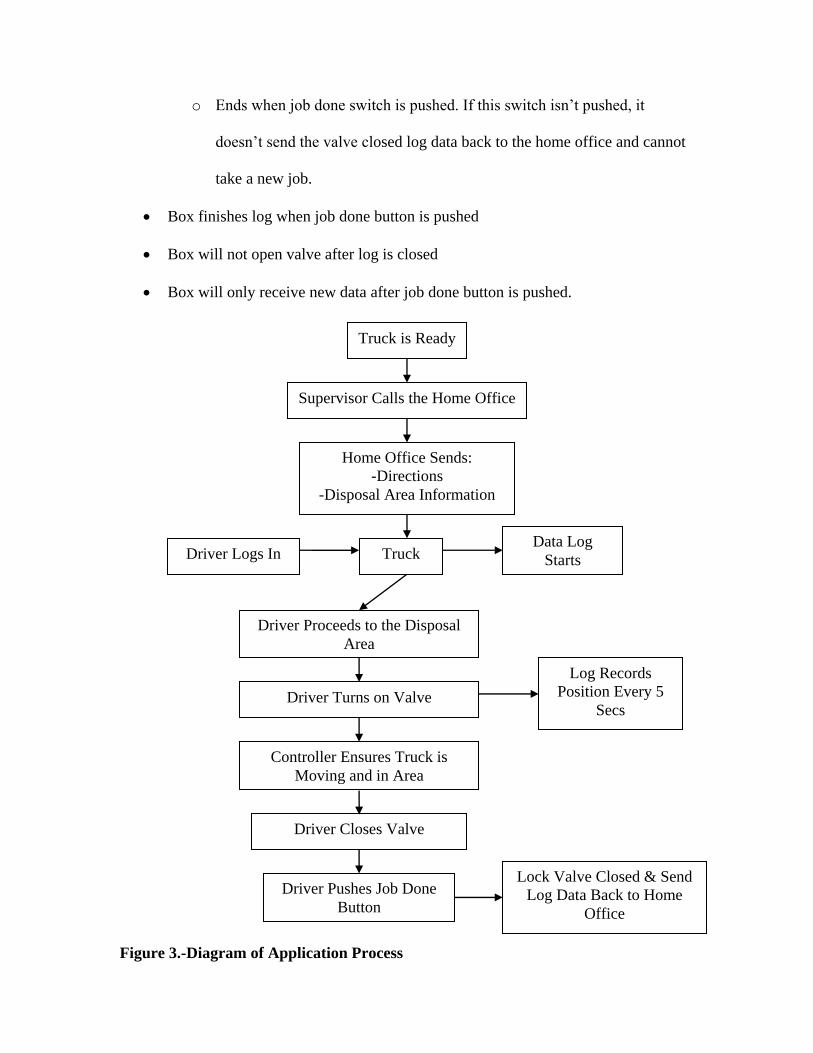
Figure 3.-Diagram of Application Process
Supervisor Calls the Home Office
Home Office Sends:
-Directions
-Disposal Area Information
Truck is Ready
Truck Driver Logs In
Driver Proceeds to the Disposal
Area
Driver Turns on Valve
Log Records
Position Every 5
Secs
Data Log
Starts
Controller Ensures Truck is
Moving and in Area
Driver Pushes Job Done
Button
Driver Closes Valve
Lock Valve Closed & Send
Log Data Back to Home
Office

8
Log consists of:
1. Truck ID-Stored in memory when “the box” is installed
2. Driver ID-Stored in memory when driver identifies self.
o Is erased when “the box” is turned off because this would make it cheaper
3. Well Site Location-is receives with area location
o Used only for that run
4. Valid area – received electronically
o Used only for that run
5. Time information – when driver identifies self
o When area and well site is received
6. Records position and time when valve is open
7. Continues recording this information periodically (~1 sec)
8. Records valve closing and why. (Which test failed or switch was used)
9. Optional: Amount disposed – Recorded at well site location
o Used only for that run
10. Records any over-rides used
Generation of Design Concepts
B3E created four proposals for the design of the controller. Two of the designs
call for B3E to develop a custom controller. The other two designs use off-the-shelf
controllers. The main difference between the designs is that the off-the-shelf controllers
have the ability to display moving maps to help the driver find the designated area.
However, these controllers are not able to complete all of the tasks listed in the

9
requirements for the controller. To use a moving map display means that we will not be
able to implement all of the tests and controls that we had intended for this system.
The following is the description detailing the two controllers that we will build ourselves:
Custom Controller Type 1 (Simple System):
No driving directions – Assume that they will be printed with a map showing location
No way to enter amount to dispose – This will be recorded at home office when the
request for a disposal area is made.
5 Lights
Valve open
Inside of Area
Vehicle Moving
Power
Log closed light/Ready for new run information
3 Buttons
Toggle switch for open/close valve
Job done button – The button will be cover switch or some other method to
prevent accidental activation.
Power Switch
Over-rides provided by either special driver identification or through Qualcomm
Custom Controller Type 2: give driving directions (optional: enter the amount disposed)
Receives driving directions through Qualcomm.
Contains:
1. Screen: -display the directions to the disposal area
-display the amount disposed (optional)
2. Lights (5): -indicates valve open/closed
-indicates whether the truck is within the correct area
-indicates whether the truck is in motion
-indicates that the log is closed and ready for a new run
-indicates that the power is on
3. Buttons (6): -toggle switch for opening/closing the valve
-“job done” button
-power switch

10
-switch to navigate between the options and to move the
cursor
-switch to change the digits
-enter/exit button (toggle switch)
Override method: by entering the password of the driver in an over-ride screen on
the controller (one of the menu choices).
The off-the-shelf controllers will use the systems that they have already created in their
operation.
Feasibility Evaluation of Possible Designs
All controllers need a GPS receiver, so this has not been included in the price quoted
Build our own controller:
Type 1-Very Simple (5 lights and 3 buttons on text display):
Cost: $25,000 in development costs for the first one (Dr. Stone, BAE Professor)
Strengths:
Simple-Easy to use. Very little training required for the driver.
Contains just the features necessary.
Tests to ensure the vehicle is moving and is within the designated area.
Can be integrated with Qualcomm or other wireless data transfer systems
The lights will clearly display the current state of the controller and any errors
No need to read English to operate.
Weaknesses:
No map or directions to tell driver where to go (Assume that this can be created
using the GIS software in the home office. They will save the map as a jpeg and
email it to supervisor who will print it on-site and give to the driver)

11
No ability to type in a password directly into the controller to over-ride. (Assume
the driver can call into the home office, and they will send an over-ride through
the Qualcomm network.)
No ability to type the amount for each disposal run into the controller to add to the
log file. (This must be reported to the home office when asking for them to send
the application area to the controller. They can then add this to the log file at the
home office at the end.)
Type 2-Simple (4 Line Text Display Screen, 5 Lights, 6 Buttons)
Cost: $50,000 in development costs for the first one (Dr. Stone, BAE Professor)
Strengths:
Simple-Easy to use. Very little training required for the driver.
Contains just the features necessary.
Tests to ensure the vehicle is moving and is within the designated area.
Can be integrated with Qualcomm or other wireless data transfer systems
The lights will clearly display the current state of the controller and any errors
Gives driver directions in text format (These need to be created by the people in
the home office when designating the area to which to apply.)
Over-ride password can be typed into the controller by driver
Amount that is to be disposed can be entered into the controller on-site.
Weaknesses:
No map to tell the driver the shape of the designated area. (Once again this can be
created at the home office and printed on-site to be given to the driver)

12
Must be able to read English to read directions
Off-the-shelf controllers:
Using Mid-Tech Controller:
Cost:
Entire system without GPS receiver $11,000
Strengths:
Displays map of designated area on color screen
Can receive shape files directly from the GIS package
It will print out log data in a job report format
Weaknesses:
Driver can just turn off the prescription map of designated area.
Logging is not automatic
Not designed to direct driver to the designated application site, but maps can be
loaded to show the landmarks to find the area.
Complicated-Large number of menus to navigate and setup.
Must be able to speak English and have some basic computer knowledge
Using Trimble Controller:
Cost:
Trimble AgGPS 170—$6750
Controller—about $1000
Total at least $8000

13
Strengths:
Is designed to help the driver find the site when background maps are loaded for
the area. Guidance system will direct driver to the site.
Maps are displayed on a color screen
Complete logging of application data—including driver information.
ESRI ArcExplorer version 2 is included with the AgGPS 170. (This is software
for the office computer that is used to make the maps of the areas and record the
data applications)
Can receive shape files directly from the GIS package
Somewhat simple for the driver to use—We can remove the unnecessary menu
options, so the driver only sees the ones needed to do his job.
Weaknesses:
Cannot prevent the driver from turning off the prescription map
Can only communicate through a flash card
Must be able to speak English and have some basic computer knowledge
14
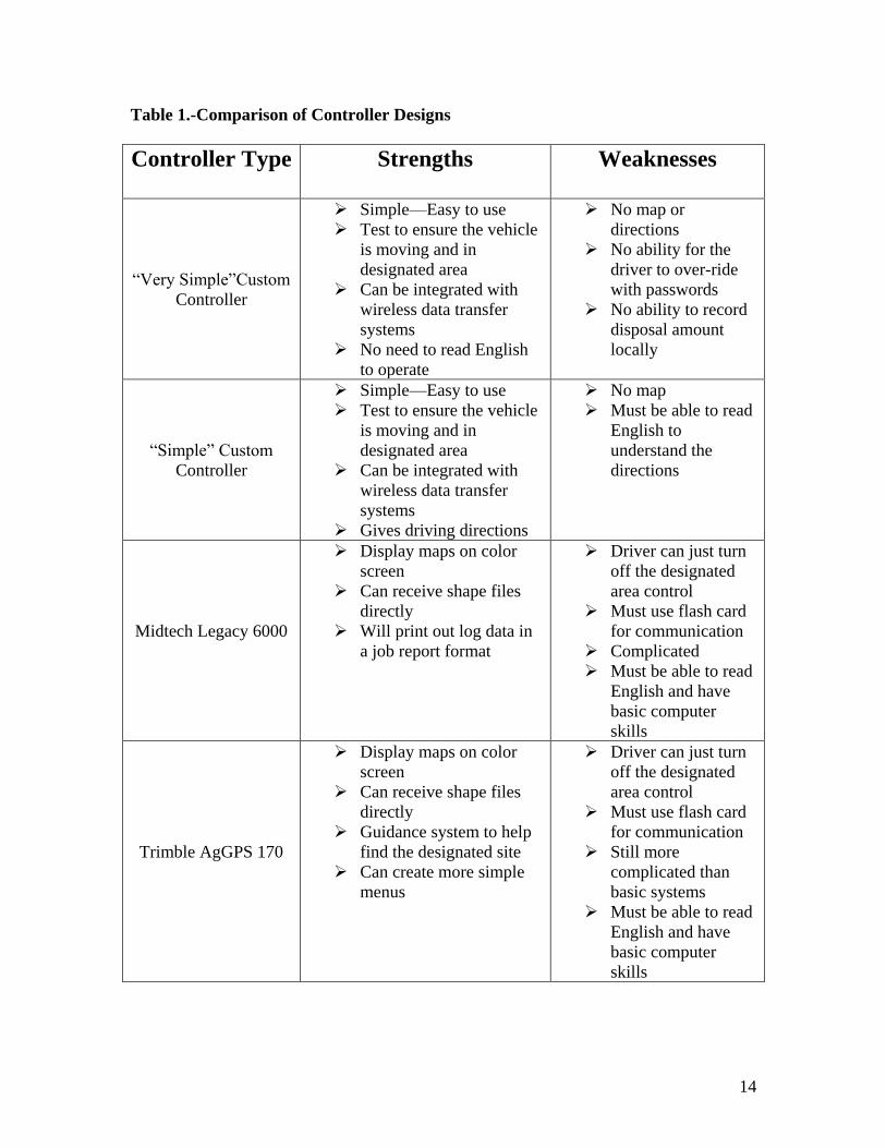
Table 1.-Comparison of Controller Designs
Controller Type Strengths Weaknesses
“Very Simple”Custom
Controller
Simple—Easy to use
Test to ensure the vehicle
is moving and in
designated area
Can be integrated with
wireless data transfer
systems
No need to read English
to operate
No map or
directions
No ability for the
driver to over-ride
with passwords
No ability to record
disposal amount
locally
“Simple” Custom
Controller
Simple—Easy to use
Test to ensure the vehicle
is moving and in
designated area
Can be integrated with
wireless data transfer
systems
Gives driving directions
No map
Must be able to read
English to
understand the
directions
Midtech Legacy 6000
Display maps on color
screen
Can receive shape files
directly
Will print out log data in
a job report format
Driver can just turn
off the designated
area control
Must use flash card
for communication
Complicated
Must be able to read
English and have
basic computer
skills
Trimble AgGPS 170
Display maps on color
screen
Can receive shape files
directly
Guidance system to help
find the designated site
Can create more simple
menus
Driver can just turn
off the designated
area control
Must use flash card
for communication
Still more
complicated than
basic systems
Must be able to read
English and have
basic computer
skills

15
Determination of Suitable Designs in the Fall Semester
The proposed designs were sent to Joe Hamilton for review. He decided that the
project should continue with the Trimble design. The facilities for creating a controller
from scratch were currently busy with many other projects. The Trimble controller also
provided the most features for its cost.
Determination of the Final Design
At the end of the final semester, we had decided on the Trimble AgGPS Field
Computer to handle our maps. We waited for a couple of months trying to purchase this
unit. We were not able to obtain it, so we started looking at alternatives. At the same
time, we realized that the single rate controllers we had been hoping to use would not
work. All of these controllers relied on a flow meter to maintain a constant rate. The
drilling mud that we would be pumping through the lines would destroy a flow meter
quickly. We realized that it would be necessary to build our own controller to just turn
on and off a valve. This meant that we could look at field computers that we had
previously disqualified because they did not support many controllers.
After looking at the field computers again, the Raven Viper stood out. This unit
was significantly cheaper than most other field computers but only supported controllers
made by Raven. Raven was one of the few companies to provide the communication
strings that operated its controllers, so we had already decided that it would be best to use
these communication strings in our custom design. The Raven Viper was easily available
and we were able to start using it soon after we made the decision to purchase it.

16
The controller was constructed with a PIC micro controller from Microchip. A
prototype board from CCS was used. The 16F877A Mini-proto board provided a power
supply, a RS232 output, and an easy to connect to header to provide access to all of the
pins on the chip. The CCS PIC-C complier was used to write the program for the chip.
The reason this products were used was that the team was familiar with the products from
class work. A final design of the system should not rely on these parts as they are only
designed for prototype use.
We decided to use ArcView because it is considered cheap among other GIS
package and it is the most widely used in this area. In addition, ArcView is available in
BAE computer lab. Furthermore, one of the BAE staff is an expert in using ArcView and
he is willing to share his knowledge to us.
Design of the Viper and Controller System
The custom controller takes the information from the Raven Viper and uses it to
control a valve. The Viper puts out messages that tell the controller if the valve is
allowed to be open. The controller also tells the Viper if the valve is open or closed. The
Viper logs this information and creates reports indicating exactly where the material was
applied. The operator also has a switch which must be on for the valve to be open. This
allows the operator to turn off the dispensing of the material at any time.
The messages from the Viper are sent by a RS-232 serial connection. This
connection uses a hardware handshaking system normally. Since the micro controller
used in this project did not have this hardware, the handshaking lines were looped back to
themselves. Pins six and four, and pins seven and eight were connected by loops of wire.

17
This meant that the Viper also saw the response it wanted and never halted the sending of
information. The Viper's messages and the controller’s response are included in
Appendix A. Notice that the Viper is setup as a Data Communications Equipment. This
means that the controller must be wired as a Data Terminal Equipment.
Another problem with the Viper is that it is possible to shut down its serial port
communications by sending too much data too fast. After experimenting with many
different timings, a setting was found that did not crash the Viper. Set the baud rate to
9600 with no parity, 8 data bits, and 1 stop bit. Then add a 100μs delay between sending
each character. Unfortunately at this speed, the controller will miss communications
from the Viper unless it checks the incoming buffer after sending each character. With a
different compiler and micro controller setup this might not be necessary.
The value switch works by grounding a pin that is pulled high by a pull-up
resistor. This was the B0 pin on the PIC 16F877A which is the external interrupt. The
switch needs to be polled continuously or on an interrupt that will detect any change in its
status. The switch is considered on when the line is grounded through the switch. When
the switch is on, this allows the valve to be turned on if the Viper has sent a message
indicating that the vehicle is in the area designated by the prescription map. If the switch
is off, the valve needs to be shut off immediately. This could also be implemented by
running the output to the valve through the switch and leave out the micro controller
altogether.
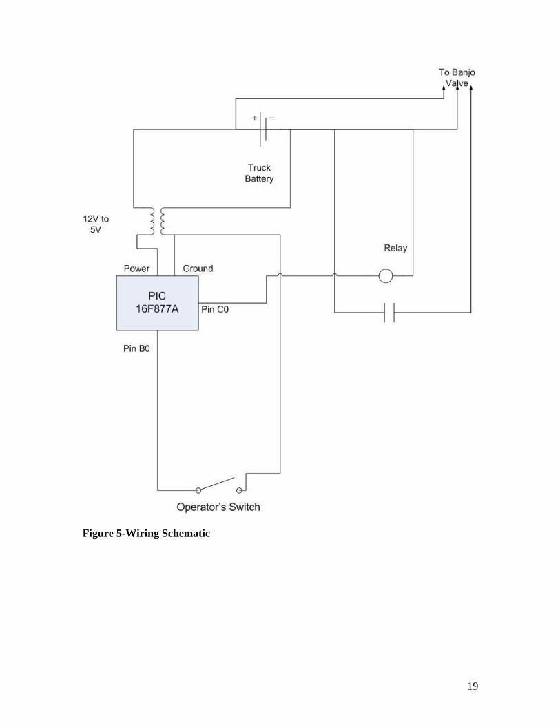
The Banjo valve is operated by three wires. Two wires are ground and twelve
volt power. The third wire is switched. When twelve volts are on this line, the valve
opens. When this line is not powered, the valve closes. The valve requires about three
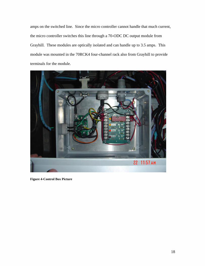
18
amps on the switched line. Since the micro controller cannot handle that much current,
the micro controller switches this line through a 70-ODC DC output module from
Grayhill. These modules are optically isolated and can handle up to 3.5 amps. This
module was mounted in the 70RCK4 four-channel rack also from Grayhill to provide
terminals for the module.
Figure 4-Control Box Picture
19
Figure 5-Wiring Schematic

20
Implementation of Arc-View Design
Downloading Maps
The permitter needs to download some maps in order to determine the suitable area. The
maps are aerial photos, road maps, watershed maps, soil type maps, and township maps.
The maps are available online for free.
Determining Disposal Area
By using ArcView, the user can overlap aerial, road, and watershed maps. First, he/she
can locate the drilling site by looking at the map. Then, the user can find the nearest area
to dispose the liquid waste material. Besides watershed profile, the soil type map is also
used to decide whether the area is suitable for dumping the liquid waste material. After
that, the user can use the township map to determine the township, town section, and
owner of the land.
Creating Prescription Map
ArcView provides features to mark a disposal area, by drawing polygon around the area.
Then, the user can create a prescription map by editing the polygon’s table. Detailed
steps are provided in the user manual.

21
Results
The Viper and the Control Box
The Viper seems to be a suitable field computer to use in this application. It is
cheaper than others, and provides the necessary information to the controller. The
control box needs to be designed for a final product. The current system is just a
prototype to allow the validation of the design concept. This makes this system very
impractical for use in a commercial product. However, the system does do its job. The
valve is turned off when it is not in the zone allowed by the Viper and turns on when in
the zone and the valve switch is on.
There are several problems in the current prototype. The biggest problem is that
the program occasionally stops receiving characters from the Viper. This seems to be
either an error in prototyping board or with the complier. A function provided with the
compiler should check whether the UART buffer has any characters in it. Occasionally
this function is stuck reporting that no characters are available. The only way to return
the micro controller to operating status is to reset it. The connections on the prototype
are definitely not suitable for use in the field. Too much vibration will cause the power
and RS-232 cables to fall out of the board. The Grayhill module is convenient for design
purposes but is inefficient for use in a final design. A single board should be built to
combine all of these components without extra wiring.
Arc-View
We created prescription maps for an area besides BAE laboratory (parking lot).
Then, we transferred the best one to Raven Viper by using flash card. After that, we

22
drove the testing vehicle to see whether the map was shown in the Raven Viper. The
map was shown as expected in the Raven Viper. It also had an icon showing current
position in relation to the prescription map.
Projected Budget
Trimble Unit $6,750.00
Fluid Controller ≈$1,000.00
Miscellaneous ≈$1,000.00
Total ≈$9,000.00
Actual Budget to Implement this System
Raven Viper $4000
Controller Box $500
Banjo Valve 1” $400
ARC-VIEW $1500
Total $6400
Conclusion
The use of GIS information to control the application of hazardous materials is
very possible. Much information is available for free on the Internet. It may take some
training to be able to use all of this information, but once learned, it makes looking at
maps for decision making very easy. Once a decision has been made, the prescription

23
map can be created following the instructions we have given. This prescription map is
transferred to the Viper. The Viper allows the use of technology that has already been
proven in precision farming to be used for this new task. The custom controller box
allows the use of the Viper without the usually required flow meter. This enables our
process to be used for the much simpler task of on or off control that is not usually an
option on precision farming techniques but is valuable in controlling the disposal of
hazardous materials. The Viper also provides a proven system for the record keeping.
All of these features make this system a viable way to control the placement of hazardous
liquid waste.

24
Appendix A. Viper-Controller Communication
Strings from the Viper
$R,TD This is a request for the controller to send a Time string
$R,CR This is a request for the controller to send its Calibration strings
$R,DR This is a request for the controller to send its Data strings
$R,TA Unknown use, respond with the actual rate.
$R,RC,xxxx This is a rate change request. The xxxx will be replaced by a number
indicating the requested rate.
Strings to the Viper
The italicized variable open is set to 1 when the valve is open and to 0 when the valve is
closed.
$R123K,AR,open\r\n Returns the actual rate to the Viper. This message is sent
about every 2.5 seconds and in response to the rate change
request and the unknown TA message.
$R123K,C1,10000001,00010001,100,0,0,785\r\n These are the calibration
$R123K,C2,720\r\n strings for the controller.
$R123K,C3,0743,open,0\r\n These are guessed values
based on information in Appendix 10
of the Raven SCS 440 manual. It
should tell the Viper that only boom 1
is in use and that the console is setup
with a fast valve to enable zero rates.
I suspect that there is an error in these
strings since the Viper will not send a
zero rate to the controller.
$R123K,D1,1,1\r\n These are the data strings. They should contain
information
$R123K,D2,1,1\r\n about the areas, volumes, and distances covered. The Viper
$R123K,D3,1,1\r\n appears to ignore these numbers so they are all set to 1.
BAD COMMAND This is not supported by the Viper, but it indicates that the
controller did not properly receive the last string from the
Viper.
BAD LOGIC This should never be seen unless the program running the
controller has become corrupted.
25
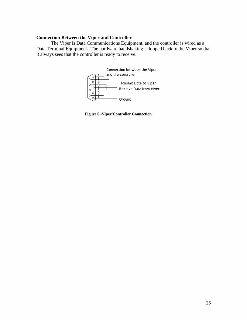
Connection Between the Viper and Controller
The Viper is Data Communications Equipment, and the controller is wired as a
Data Terminal Equipment. The hardware handshaking is looped back to the Viper so that
it always sees that the controller is ready to receive.
Figure 6.-Viper/Controller Connection

26
Appendix B. Instructions to Setup and Operate the Viper with the Controller
Installation of the Control Box
Power Connection
The Power for the box is connected to the switched power supply from the Viper.
This is the orange wire from the Viper. This only provides the box power when the Viper
is on. This prevents the box from draining battery power when it is not in use and makes
sure that it is on any time it may need to be used. The power connector is the two pin
Deutsch Connector. The polarity must be correct or severe damage will occur. The
wires on the inside are colored red for positive and black for ground. Ensure that the
power connector lines up properly.
Valve on/off Switch
This is the top two pins of the four pin Deutsch Connector. The switch needs to
connect the two wires when the user wants to allow the valve to be on. The black wire is
a ground. The other wire is only connected to ground when the switch is in the on
position.
Valve Connection
The valve is connected by the three pin round Deutsch Connector. This pin
provides power on the red and black wires to the valve. The third wire is controlled
through the relay to open and close the valve.
Viper Connection

27
This is a DB9 (nine pin) connection. Plug the line labeled Console from the Viper
into this connector.
Viper Setup
Follow the directions given in the Viper manual.
During the product control setup, the Viper will ask for the controller to be used.
For the console, chose the SCS 440. This is the console that the controller in the box tries
to emulate.
On the serial port setup or commport setup, depending on the version of Viper, for
the console connection chose:
Baud: 9600
Parity: None
Stop bits: 1
Data bits: 8
Since the controller only changes one valve, the number of booms should be set to
1. The section width should be the length of this boom.
Running the Viper and the Controller
The prescription map created in ARC-VIEW must be placed in the correct
directory on the Viper’s flash card. This should be the Rx Map directory, but the Viper
manual has more information in its appendix on creating prescription maps. To start the
application process, the driver needs to follow the instructions to start a job. These are
listed in the Viper manual with color pictures showing the menus that should be used.

28
Since the actual method varies depending on the version of the Viper that is being used,
we will leave the specific steps out of this report. Instead, refer the manual that
corresponds with the version that is being used. During the process of starting a job,
several decisions must be made. The operator needs to pick the option to turn on variable
rate application and to record the application data. To enable the variable rate
application, the driver will need to select the prescription map that the permitter has
created and placed on the Viper’s flash card. The driver will need to select the product
that is being varied from the prescription map. This product has been named DRILLING
in all of our examples. These choices should let the driver start the application process.
Once the application is finished, follow the directions to close the job. The Raven will
then record the information to the Flash disk for later transfer to a computer for
permanent filing.

29
Appendix C. Source Code for the PIC 16F877A with CCS compiler
// the pretend SCS 440
#include <16F877a.h>
#use delay(clock=20000000)
#fuses HS,NOWDT
#use rs232(baud=9600,parity=N,xmit=PIN_C6,rcv=PIN_C7)
#define TIME_TO_DELAY 100 //time to delay between character sends in us.
int typeInput(char *viperString);
void answerViper(int kind);
int rateChange(char *rateInfo);
int get_raven(char *viperstring, int maxlength);
int1 open;
int count;
int1 allowOpen;
char activeArray[50];
int arraySend;
int1 something_to_send;
int1 two_part_message;
int1 current_signal;
#int_timer1
/*This timer interrupts about every 100ms. It counts for 25 interrupts to reach
every 2.5 seconds. The first action of this timer is too send a message indicating the
actual rate to the Viper. It then checks the variable current_signal. Current_signal
is set every time Viper receives a new rate from the Viper. If a new message has not
been
received in the 2.5 seconds, it turns off the valve. This is what closes the valve usually
since the Viper does not always send zero rates.*/
clock_isr() {
if(++count > 25)
{
answerViper(1);
if(current_signal)
{
current_signal = 0;
}
else
{
output_high(PIN_C0);
open = 0;
allowOpen = 0;
}

30
count = 0;
}
}
//The following interrupt handles the manual open/close value switch
//The external interrupt on pin B0 requires that the type of edge that
//triggers the the interrupt be set. Since I want to capture both
//this interrupt service routine changes the trigger depending on the
//state of the switch after the interrupt
#int_EXT
EXT_isr()
{
delay_ms(10); //debounce the button
if(input(PIN_B0) == 0)
{
ext_int_edge(L_TO_H);
if(allowOpen == 1)
{
output_low(PIN_C0);
open = 1;
}
}
else
{
ext_int_edge(H_TO_L);
output_high(PIN_C0);
open = 0;
}
}
void main(void)
{
char fromViper[20];
int type; //type = 0 for unknown
//type = 1 for rate change
//type = 2 for calibration string request
//type = 3 for data string request
//type = 4 for time request
//type = 5 for actual rate request (TA?)

31
int1 good=0;
open = 0;
count = 0;
allowOpen = 0;
arraySend = 0;
something_to_send = 0;
two_part_message = 0;
if(input(PIN_B0) == 1) //set the condition for the initial external interrupt
{
ext_int_edge(H_TO_L);
}
else
{
ext_int_edge(L_TO_H);
}
setup_timer_1( T1_INTERNAL | T1_DIV_BY_8 );
enable_interrupts(INT_TIMER1);
enable_interrupts(INT_EXT);
enable_interrupts(GLOBAL);
while(TRUE)
{
/*This first section calls the function that records the string from
the viper. This function returns a 0 if the string was not properly
recorded. A zero makes the program start over on reading from the viper
and prevents the rest of the program from operating on a bad string*/
do
{
good=get_raven(fromViper,20);
if(!good){
output_low(PIN_B5);} //turn on the red led if the message is bad
}while(!good);
output_high(PIN_B5); //turn off the red led if the message is good
output_low(PIN_A5); //turn on the green led if the message is good
type = typeinput(fromViper); //calls a function to determine the request
type
if(type == 1) //if the request was for a rate change, determine the
{ //requested rate
32
allowOpen = ratechange(fromViper);
current_signal = 1;
}
/*Opens the valve if both the manual switch and the rate from the raven
are requesting that the valve be open*/
if(input(PIN_B0) == 0 && allowOpen == 1)
{
output_low(PIN_C0);
open = 1;
}
else
{
output_high(PIN_C0);
open = 0;
}
/*Send the required reponse back to the viper*/
answerViper(type);
output_high(PIN_A5); //turn off the yellow led
output_high(PIN_B4); //turn off the green led
}
}
int typeInput(char *viperString)
{
/*This function checks the message type from the Viper and returns a value based on that
type.*/
int i = 0;
while(viperString[i]!=',')
{
i++;
}
i++;
if(viperString[i] == 'R' && viperString[(i+1)] == 'C')
return 1; //rate change
if(viperString[i] == 'C' && viperString[(i+1)] == 'R')
return 2; //calibration string request
if(viperString[i] == 'D' && viperString[(i+1)] == 'R')
return 3; //data string request\r\n
if(viperString[i] == 'T' && viperString[(i+1)] == 'R')
return 4; //time request
if(viperString[i] == 'T' && viperString[(i+1)] == 'A')
return 5; //actual rate request?

33
return 0; //do not know the type of request
}
void answerViper(int kind)
{
/*The activeArray is the string that currently needs to be sent to the Viper. This function
loads the proper string into activeArray depending on the type of message that the Viper
sent. The first part of the function checks that the controller is not currently in the middle
of sending a string. If it is, it sends the old message quickly before replacing the
activeArray.*/
/*The compiler does not allow strings beyond a certain length, so the calibration strings
must be sent in two parts. The second part of the calibration string depends on if the
valve is open or not so that is tested for before loading the second part of the string. If
the string has completed it changes the variables to indicate that.*/
while(something_to_send || two_part_message)
{
putc(activeArray[arraySend++]);
if(activeArray[arraySend] == 0)
{
if(two_part_message)
{
if(open)
{
strcpy(activeArray, "$R123K,C2,720\r\n$R123K,C3,0743,1,0\r\n");
}
else
{
strcpy(activeArray, "$R123K,C2,720\r\n$R123K,C3,0743,0,0\r\n");
}
two_part_message = 0;
arraySend = 0;
}
else
{
something_to_send = 0;
}
}
delay_us(TIME_TO_DELAY);
}
something_to_send = 1;
arraySend = 0;

34
switch(kind)
{
case 0:
strcpy(activeArray, "BAD COMMAND\r\n");
break;
case 1:
if(open)
{strcpy(activeArray, "$R123K,AR,1\r\n");}
else
{strcpy(activeArray, "$R123K,AR,0\r\n");}
break;
case 2:
two_part_message = 1;
strcpy(activeArray, "$R123K,C1,10000001,00010001,100,0,0,785\r\n");
break;
case 3:
strcpy(activeArray, "$R123K,D1,1,1\r\n$R123K,D2,1,1\r\n$R123K,D3,1,1\r\n");
break;
case 4:
strcpy(activeArray, "$R123K,TD,17:00,03/01/2005,1\r\n");
break;
case 5:
if(open)
{strcpy(activeArray, "$R123K,AR,1\r\n");}
else
{strcpy(activeArray, "$R123K,AR,0\r\n");}
break;
default:
strcpy(activeArray, "BAD LOGIC\r\n");
}
}
int rateChange(char *rateInfo)
/*This function returns the rate requested by the Viper in the
rate change request string*/
{
int i = 0;
int comma_count = 0;
for(comma_count = 0; comma_count < 2; comma_count++)
{
while(rateInfo[i]!=',') //advance the string to the second comma
35
{
i++;
}
i++;
}
/*This section reads the rate information. If any digit is a non-zero in
the rate number, it returns a one to turn on the valve. Otherwise the
while loop will end and the function will return a zero.*/
while(rateInfo[i] >= '0' && rateInfo[i] <= '9')
{
if(rateInfo[i] != '0')
{
return 1;
}
i++;
}
return 0;
}
int get_raven(char *viperOutput, int maxlength)
{
int len=0;
char c;
/*The following do...while loop continues until a $ is received from the Viper.
The $ is the start of a message from the Viper. This prevents the controller from
starting the recording in the wrong place.*/
do
{
/*The function kbhit returns a one if there is a character received and waiting in the
UART buffer. This loop therefore continues until a character is received.*/
while(!kbhit())
{
if(something_to_send) //check if there is anything to send
{
putc(activeArray[arraySend++]); //send one character from the activeArray
if(activeArray[arraySend] == 0) //check for the end of the activeArray
{
if(two_part_message) //if the message has two parts, load the second.
{
if(open)
{
strcpy(activeArray, "$R123K,C2,720\r\n$R123K,C3,0743,1,0\r\n");
}
36
else
{
strcpy(activeArray, "$R123K,C2,720\r\n$R123K,C3,0743,0,0\r\n");
}
two_part_message = 0;
arraySend = 0;
}
else
{
something_to_send = 0;
}
}
delay_us(TIME_TO_DELAY); //wait for the TIME_TO_DELAY to prevent from
overloading
//the Viper's serial communications and shutting it down.
}
}
c = getc();
}
while(c != '$'); //only start recording a string if the start
//character of $ was received.
/*The function kbhit returns a one if there is a character received and waiting in the
UART buffer. This loop therefore continues until a character is received.*/
while(!kbhit())
{
if(something_to_send) //check if there is anything to send
{
putc(activeArray[arraySend++]); //send one character from the activeArray
if(activeArray[arraySend] == 0) //check for the end of the activeArray
{
if(two_part_message)
{
if(open)
{
strcpy(activeArray, "$R123K,C2,720\r\n$R123K,C3,0743,1,0\r\n");
}
else
{
strcpy(activeArray, "$R123K,C2,720\r\n$R123K,C3,0743,0,0\r\n");
}
two_part_message = 0;
arraySend = 0;
}
else
{

37
something_to_send = 0;
}
}
delay_us(TIME_TO_DELAY);//wait for the TIME_TO_DELAY to prevent from
overloading
//the Viper's serial communications and shutting it down.
}
}
c=getc(); //get the first letter after the $
output_low(PIN_B4); //turn on the yellow LED to show that the recording of a
message has started.
--maxlength; //subtract one from the length of the string to leave room for the null
character.
/*This do...while loop records the string until either a new line is received or the string
is full. It also outputs messages when it is not receiving the message. If it recieves an
invalid character or reaches the end of the message, it returns a 0 indicating that the
message was not received properly.*/
do {
if ((c<=' ')||(c>='~')||(c=='$'))
return 0; //return not good if not an alphanumeric or if another $ is reached
if(!(len<maxlength))
return 0; //return not good if max length of the string is reached
viperOutput[len]=c;
len++;
/*The function kbhit returns a one if there is a character received and waiting in the
UART buffer. This loop therefore continues until a character is received.*/
while(!kbhit())
{
if(something_to_send) //check if there is anything to send
{
putc(activeArray[arraySend++]); //send one character from the activeArray
if(activeArray[arraySend] == 0) //check for the end of the activeArray
{
if(two_part_message)
{
if(open)
{
strcpy(activeArray, "$R123K,C2,720\r\n$R123K,C3,0743,1,0\r\n");
}
else
{
strcpy(activeArray, "$R123K,C2,720\r\n$R123K,C3,0743,0,0\r\n");
38
}
two_part_message = 0;
arraySend = 0;
}
else
{
something_to_send = 0;
}
}
delay_us(TIME_TO_DELAY);//wait for the TIME_TO_DELAY to prevent from
overloading
//the Viper's serial communications and shutting it down.
}
}
c=getc();
} while(c!=13); //stop creating string when a new line is received
viperOutput[len]=0; //add the null character to indicate the end of the string
return 1; //string was recorded correctly
}

39
Appendix D. ArcView Manual
I. STARTING ARCVIEW
Open ArcView program
The window below will pop up
Select ‘with new View’
Click “OK” and ArcView will show this window
Click “No”
40
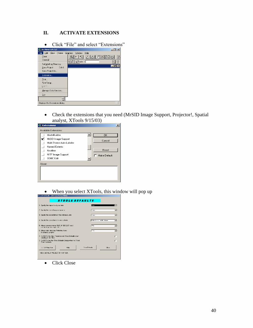
II. ACTIVATE EXTENSIONS
Click “File” and select “Extensions”
Check the extensions that you need (MrSID Image Support, Projector!, Spatial
analyst, XTools 9/15/03)
When you select XTools, this window will pop up
Click Close
41
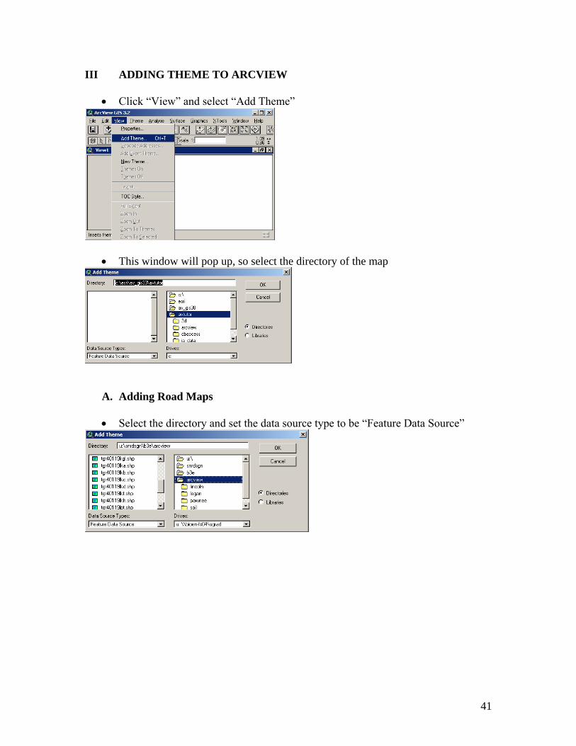
III ADDING THEME TO ARCVIEW
Click “View” and select “Add Theme”
This window will pop up, so select the directory of the map
A. Adding Road Maps
Select the directory and set the data source type to be “Feature Data Source”

42
Check on the legend and the map will be shown
B. Adding Aerial Maps
Select the directory and set the data source type to be “Image Data Source”
Check on the legend and the map will be shown
43
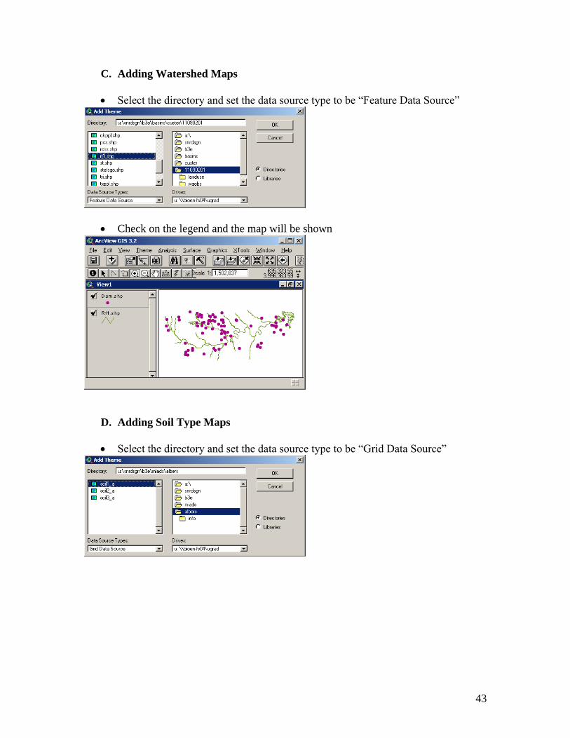
C. Adding Watershed Maps
Select the directory and set the data source type to be “Feature Data Source”
Check on the legend and the map will be shown
D. Adding Soil Type Maps
Select the directory and set the data source type to be “Grid Data Source”
44
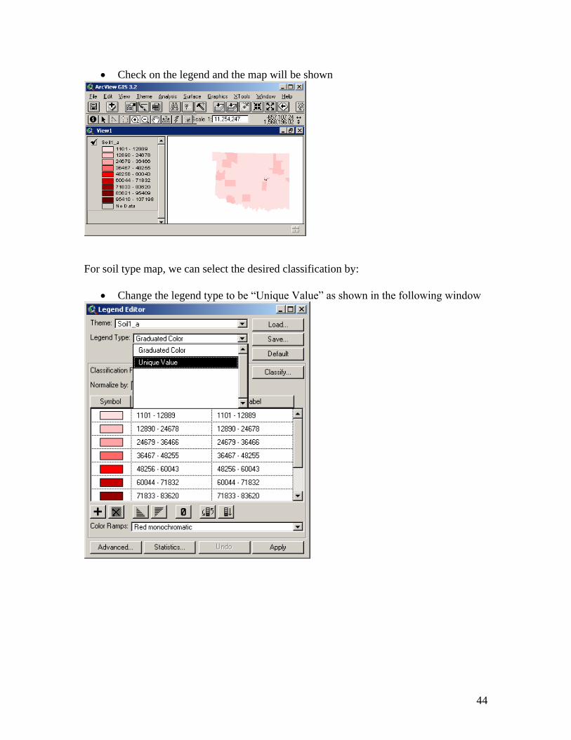
Check on the legend and the map will be shown
For soil type map, we can select the desired classification by:
Change the legend type to be “Unique Value” as shown in the following window
45
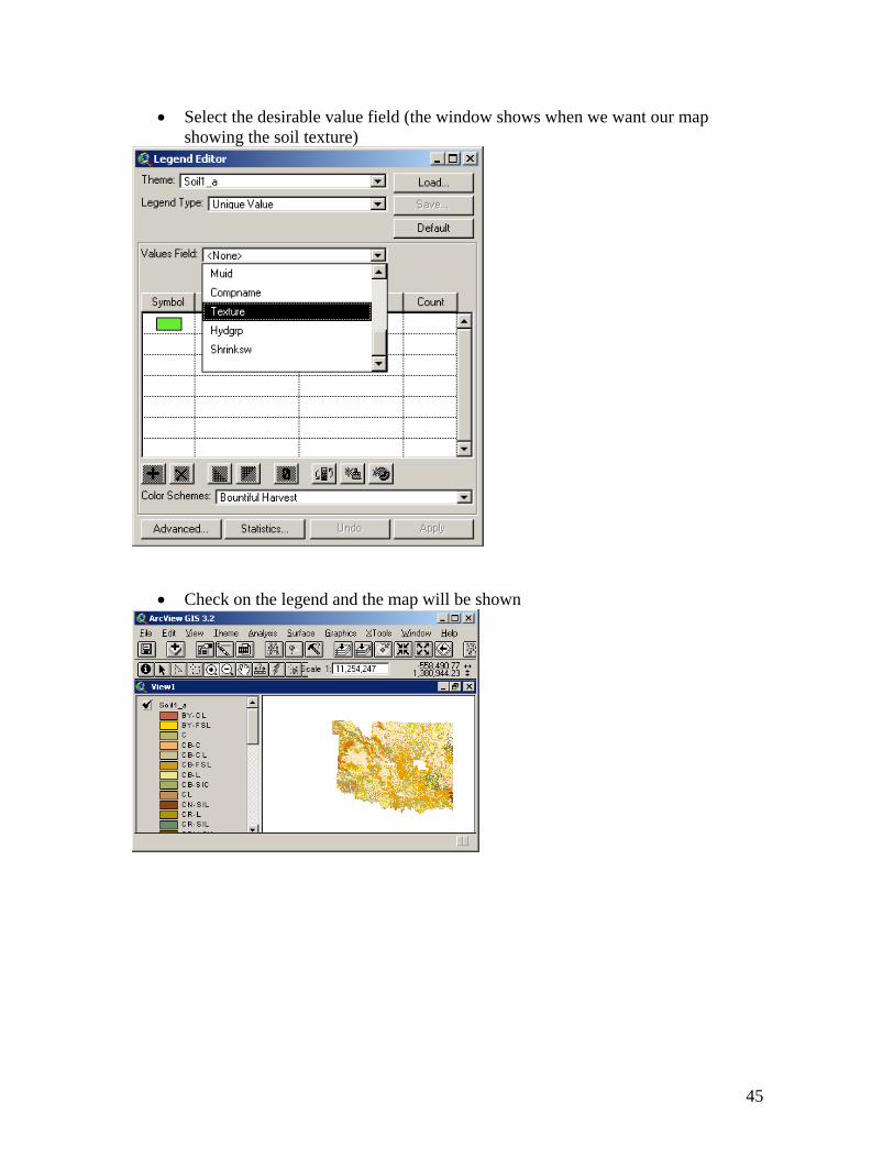
Select the desirable value field (the window shows when we want our map
showing the soil texture)
Check on the legend and the map will be shown
46
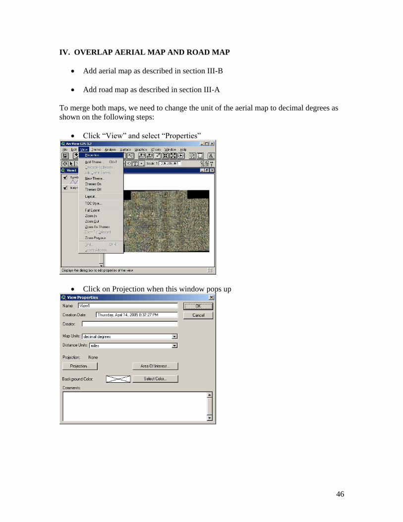
IV. OVERLAP AERIAL MAP AND ROAD MAP
Add aerial map as described in section III-B
Add road map as described in section III-A
To merge both maps, we need to change the unit of the aerial map to decimal degrees as
shown on the following steps:
Click “View” and select “Properties”
Click on Projection when this window pops up

47
Select the category to be “UTM-1983”
Select the type according to the zone number of the area, for example Payne
County is in zone 14
48
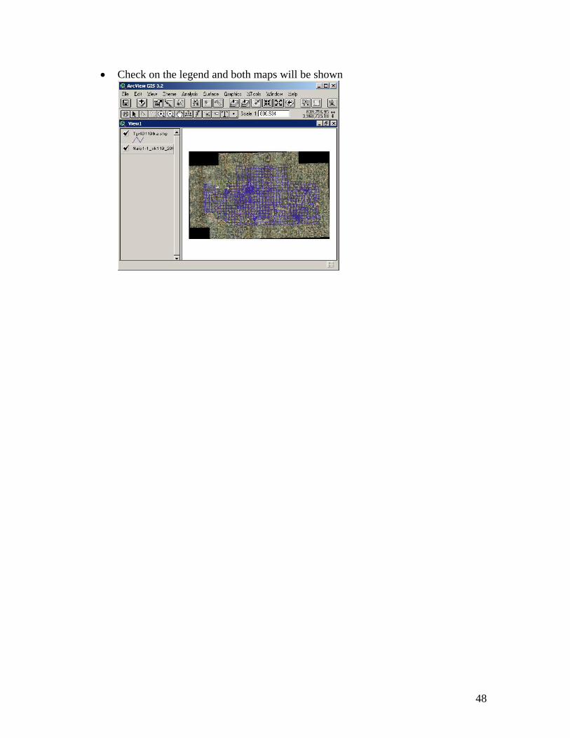
Check on the legend and both maps will be shown
49
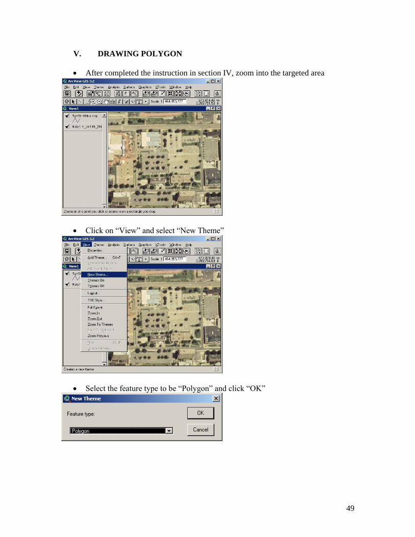
V. DRAWING POLYGON
After completed the instruction in section IV, zoom into the targeted area
Click on “View” and select “New Theme”
Select the feature type to be “Polygon” and click “OK”

50
Select the desired directory and type the file name
Click on the drop down arrow located on the bottom right corner of the following
icon. Select the polygon shape (it is the sixth option from the top)

51
Click on the edges of the polygon, and then double click on the last point
The polygon will appear as shown

52
VI. MAKING PRESCRIPTION MAP
A. Drawing the Boundaries of the Application Area
After drawing polygon of our application area, we can determine the boundaries by
drawing outer polygons following the steps below:
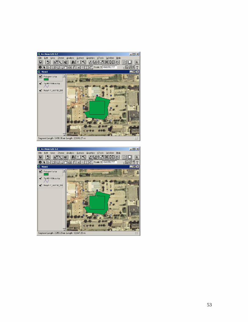
Click on the drop down arrow of the icon, and select the last option as shown
below
Draw two different outer polygons as shown in the next four windows
53

54
B. Edit Prescription Map Table
Click “Theme” and select “Table”

55
The table will be shown as following
Click “Edit” and select “Add Field” to add another column for the table
When this window shows up, change the properties of the column

56
The new column will be shown as the following
Select the polygon of which properties need to be changed
Click “Field” and select “Calculate”
Select “=” on the “Requests” list
57
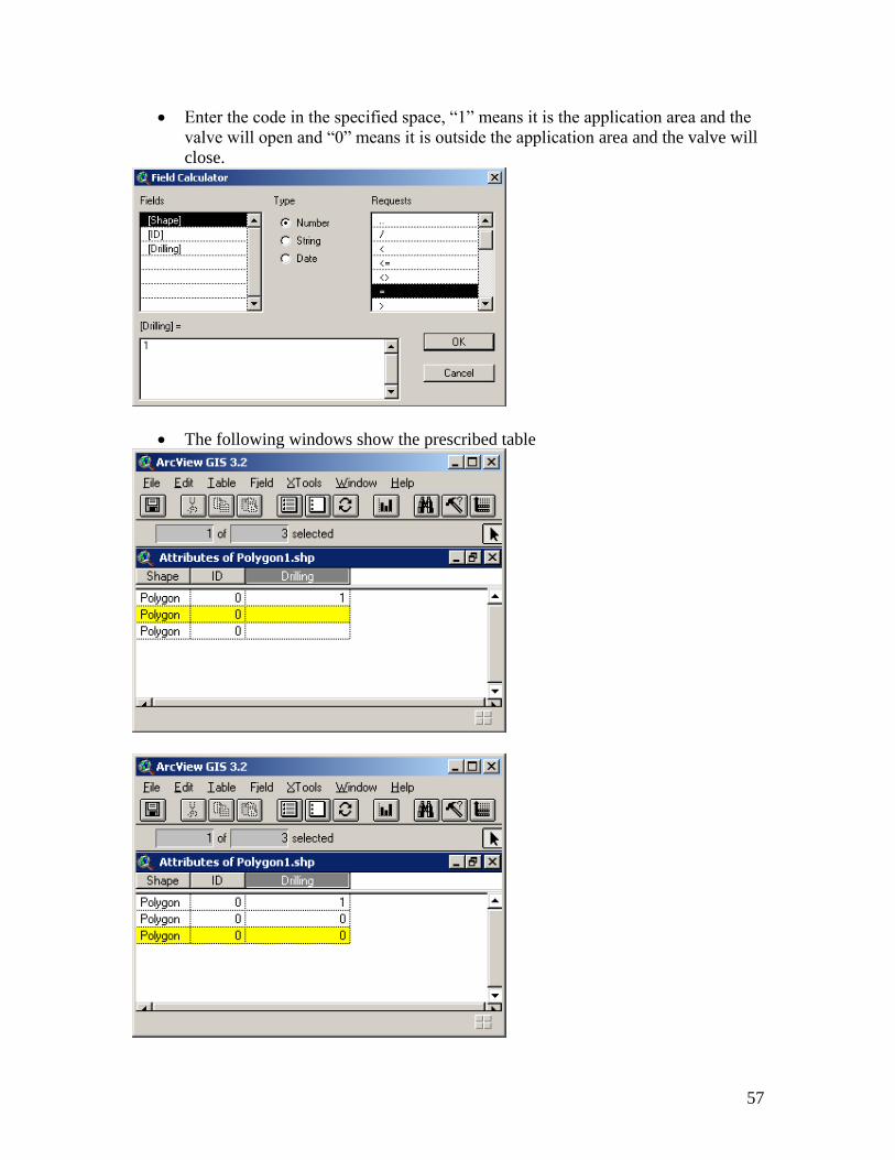
Enter the code in the specified space, “1” means it is the application area and the
valve will open and “0” means it is outside the application area and the valve will
close.
The following windows show the prescribed table

58
Click “Theme” and select “Stop Editing” to stop editing the polygons (before stop
editing polygons, don’t highlight any polygon on the maps)
When the following window pops up, click “Yes”

59
VII. PROJECTING UNITS OF POLYGON
After we draw a polygon on aerial map, we need to project the units to decimal degrees
so that we can put it on the road map using the following steps:
Click on “View” and select “Properties”
Change the map units to meters and click “OK”
Click on the “change projection” icon (first icon from the right)
60
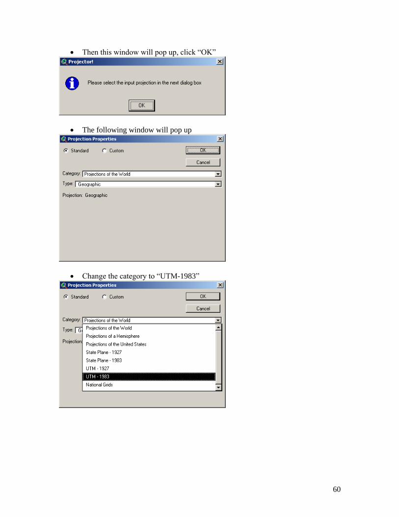
Then this window will pop up, click “OK”
The following window will pop up
Change the category to “UTM-1983”

61
Change the type according to the zone of the area (for example, Payne County is
in zone 14)
Select output units to “decimal degrees” and click “OK”
Then, this window will pop up. Select “Yes” if you want to recalculate area,
perimeter, and length using the new units. Otherwise, select “No”
Click “Yes” to add projected polygon as a theme

62
Select the View to show the new polygon
Select the desired saving directory and rename the polygon file
After completing above steps, the polygon can be overlapped on the road map

63
Appendix D. Download Instructions
MAPS WEBSITE ADDRESS
1. Aerial Photo Maps http:// 139.78.101.190/2003img1/
2. Watershed Profile http://www.epa.gov/waterscience/basins/b3webdwn.htm
3. Road Maps http://arcdata.esri.com/data/tiger2000/tiger_download.cfm
4. Township Maps
http://www.ok.nrcs.usda.gov/technical/GIS/County%20Base%20Maps/plss_page.html
5. Soil type Maps On CD
DOWNLOADING MAPS FROM WEBSITE
A. Aerial Photo Maps
1. Browse the aerial photo map website
2. Click on the county, which you want to download
3. Select save
4. Open those files to unzip them
5. Click Extract
6. Then click ok to finish unzip them
B. Watershed Profile
1. Open the watershed profile website
2. Click on “Surf Your Watershed”, under the heading of “Data from the web”
3. On the “Surf Your Watershed” page, click on “Locate Your Watershed” picture
4. Use “Find Place” to search watersheds of the desired county
5. You can see the list of watersheds under “Watersheds by County”
6. Open another window for the watershed profile website and click on
http://www.epa.gov/waterscience/ftp/basins/gis_data/huc
7. Click on the desired watershed number
8. Open the core.exe file
9. Select save
10. Unzip the file
C. Road Maps
1. Open the road map website
2. Select the desired state
3. Select the county and click “Submit Selection”
4. Check on “Line Features-Roads” and click “Proceed to Download”
5. Click “Download File”
6. Select save
7. Unzip the file
D. Township Maps
1. Open the township map website

64
2. Click on the desired county
3. Save the file