atlantic water gardens waterscapes manual
TRANSCRIPT

I N S T R U C T I O N M A N U A L
www.WAT E R S C A P E S I N T E R N AT I O N A L .com
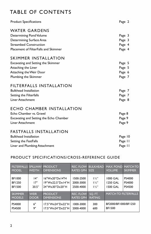
Product Specifications Page 2
WATER GARDENSDetermining Pond Volume Page 3Determining Surface Area Page 3Streambed Construction Page 4Placement of FilterFalls and Skimmer Page 4
SKIMMER INSTALLATIONExcavating and Setting the Skimmer Page 5Attaching the Liner Page 5Attaching the Weir Door Page 6Plumbing the Skimmer Page 7
F ILTERFALLS INSTALLATIONBulkhead Installation Page 7Setting the Filterfalls Page 7Liner Attachment Page 8
ECHO CHAMBER INSTALLATIONEcho Chamber vs. Gravel Page 8Excavating and Setting the Echo Chamber Page 9Liner Attachment Page 9
FASTFALLS INSTALLATIONBulkhead Installation Page 10Setting the FastFalls Page 11Liner and Plumbing Attachment Page 11
TABLE OF CONTENTS
2
PRODUCT SPECIFICATIONS/CROSS-REFERENCE GUIDE
FILTERFALLSMODEL
BF1000BF1250BF1500
SKIMMERMODELS
PS4000PS4500
SPILLWAYWIDTH
14” 17” 20.5”
WEIR DOOR
6" 9"
BULKHEAD SIZE
1½” 1½” 1½”
SQ. FT. RATING
300 600
MAX. PONDVOLUME
1000 GAL1250 GAL1500 GAL
MATCH TO SKIMMER
PS4000PS4000PS4500
REC. FLOW RATES GPH
1500-2500 2000-3000 2500-4000
REC. FLOWRATES GPH
1000-3000 2000-4000
PRODUCT DIMENSIONS
16"Wx20”Dx14"H19”Wx22.5”Dx14”H24”Wx30”Dx20”H
PRODUCTDIMENSIONS
17.5”Wx24”Dx22”H17.5”Wx24”Dx22”H
MATCH TO FILTERFALLS
BF2000/BF1000/BF1250BF1500

3
POND VOLUME It is important to calculate the estimated water volume before you begin construction, and then re-calculate final water volume when your project is completed. Estimating water volume pre-construction is a step that is often skipped by many homeowners and contractors. A water garden with undersized filtration can prove to be a maintenance nightmare.
TO DETERMINE POND VOLUME
Multiply (in feet) the average length x the average width x the average depth to find cubic feet of pond volume. Multiply cubic feet x 7.48 = gallons.
WATER GARDENS
SURFACE AREA When using any pond skimmer it is important to keep the surface area (in square feet) of the pond in mind. Upon start-up, the pump sends water from the bottom reservoir to the top of the waterfall and/or streambed. The water must then fill, from top to bottom, the waterfalls and streambed until it eventually re-enters the pond and the water levels equalize. During water in transition process, the water level of the bottom reservoir is continually dropping. If the streambed is built improperly, or is built too big, the water level of the bottom reservoir could drop below the opening in the skimmer before the water levels equalize. This would result in the pump running dry and starving for water. This situation can be easily avoided by using the formula provided to calculate the surface area of your pond. With that number, you can then determine the maximum surface area of waterfalls and streambed that your pond can accomodate.
TO DETERMINE SURFACE FOOTAGE Multiply (in feet) the average length x the average width = total square feet of the pond surface area. Multiply the surface area of the pond x .5 = maximum surface area for falls.
10’
5’
3’3”
8’
Use the product specification/cross reference guide on page 2 to verify the maximum pond volume and flow rates for your Waterscapes Equipment.
LENGTH
WIDTHDEPTH
Figure 1.
Figure 2.
EXAMPLE10’ x 5’ = 50sq ft pond surface area50sq ft x .5 = 25sq ft stream surface area

4
PLACEMENT OF THE FILTERFALLS AND SKIMMER Now that you have determined the size of the pond, waterfalls and filter system, it is time to determine the placement of the components. Whenever possible, it is best to position the Skimmer and FilterFalls directly across from each other at opposite ends of the pond. This setup creates a current that pulls surface debris into the Skimmer. If the Skimmer and FilterFalls are placed too close together, or the pond has an unusual shape, dead areas can occur. These dead areas can be eliminated with the use of multiple falls or multiple skimmers.
STREAMBED CONSTRUCTION Using proper streambed construction techniques can limit the transitional water needed to fill the streambed and enables the system to function optimally. Transitional water is determined by the height that the weir rock extends above the liner at the spillway opening. Maintaining the shortest distance possible between the top of the weir rock and the liner is a crucial component to a properly functioning water garden. Figure 3 displays two examples of proper construction techniques for minimal transitional water.
Figure 4 is an example of improper streambed construction. Stone, gravel and foam can be combined to make a barrier and create a waterfall, but that barrier will never be watertight. When the pump is turned off, the water will always drain down to the highest point of the liner. Improper construction greatly increases the water in transition.
Figure 3.
Top of linerTop of water
Transitional Water
Top of linerTop of water
Transitional Water
Figure 4.
Top of liner
Top of water
Transitional Water
5
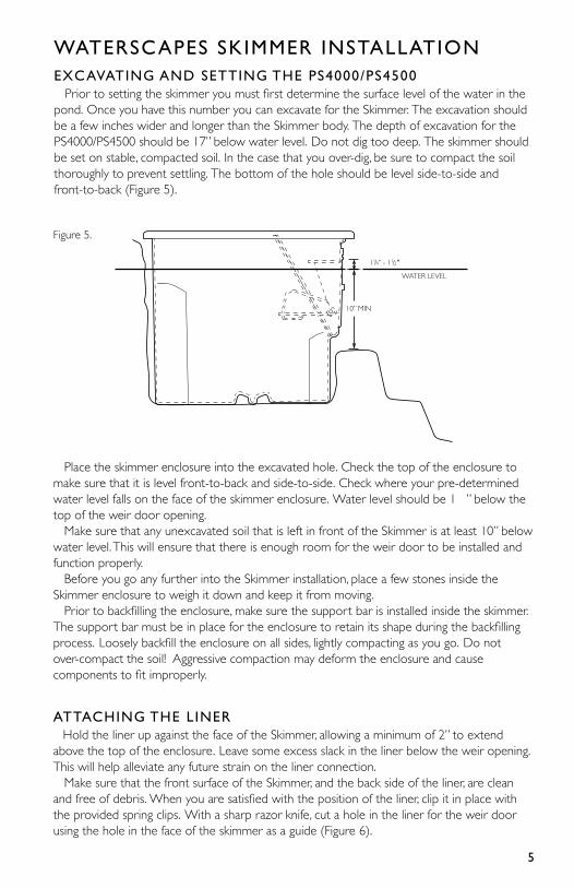
WATERSCAPES SKIMMER INSTALLATIONEXCAVATING AND SETTING THE PS4000/PS4500 Prior to setting the skimmer you must first determine the surface level of the water in the pond. Once you have this number you can excavate for the Skimmer. The excavation should be a few inches wider and longer than the Skimmer body. The depth of excavation for the PS4000/PS4500 should be 17” below water level. Do not dig too deep. The skimmer should be set on stable, compacted soil. In the case that you over-dig, be sure to compact the soil thoroughly to prevent settling. The bottom of the hole should be level side-to-side and front-to-back (Figure 5).
Place the skimmer enclosure into the excavated hole. Check the top of the enclosure to make sure that it is level front-to-back and side-to-side. Check where your pre-determined water level falls on the face of the skimmer enclosure. Water level should be 1¼” below the top of the weir door opening. Make sure that any unexcavated soil that is left in front of the Skimmer is at least 10” below water level. This will ensure that there is enough room for the weir door to be installed and function properly. Before you go any further into the Skimmer installation, place a few stones inside the Skimmer enclosure to weigh it down and keep it from moving. Prior to backfilling the enclosure, make sure the support bar is installed inside the skimmer. The support bar must be in place for the enclosure to retain its shape during the backfilling process. Loosely backfill the enclosure on all sides, lightly compacting as you go. Do not over-compact the soil! Aggressive compaction may deform the enclosure and cause components to fit improperly.
ATTACHING THE LINER Hold the liner up against the face of the Skimmer, allowing a minimum of 2” to extend above the top of the enclosure. Leave some excess slack in the liner below the weir opening. This will help alleviate any future strain on the liner connection. Make sure that the front surface of the Skimmer, and the back side of the liner, are clean and free of debris. When you are satisfied with the position of the liner, clip it in place with the provided spring clips. With a sharp razor knife, cut a hole in the liner for the weir door using the hole in the face of the skimmer as a guide (Figure 6).
Figure 5.
WATER LEVEL
11/4” - 11/2”
10” MIN
6
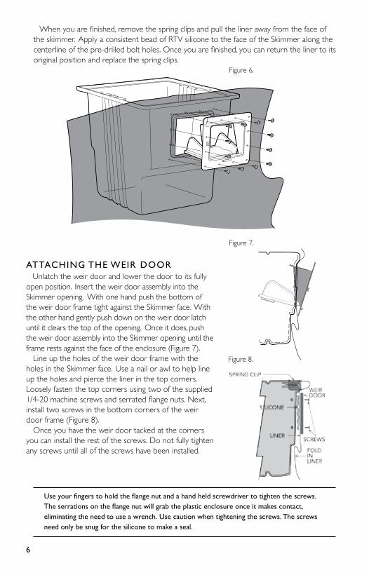
ATTACHING THE WEIR DOOR Unlatch the weir door and lower the door to its fully open position. Insert the weir door assembly into the Skimmer opening. With one hand push the bottom of the weir door frame tight against the Skimmer face. With the other hand gently push down on the weir door latch until it clears the top of the opening. Once it does, push the weir door assembly into the Skimmer opening until the frame rests against the face of the enclosure (Figure 7). Line up the holes of the weir door frame with the holes in the Skimmer face. Use a nail or awl to help line up the holes and pierce the liner in the top corners. Loosely fasten the top corners using two of the supplied 1/4-20 machine screws and serrated flange nuts. Next, install two screws in the bottom corners of the weir door frame (Figure 8). Once you have the weir door tacked at the corners you can install the rest of the screws. Do not fully tighten any screws until all of the screws have been installed.
When you are finished, remove the spring clips and pull the liner away from the face of the skimmer. Apply a consistent bead of RTV silicone to the face of the Skimmer along the centerline of the pre-drilled bolt holes. Once you are finished, you can return the liner to its original position and replace the spring clips.
Use your fingers to hold the flange nut and a hand held screwdriver to tighten the screws. The serrations on the flange nut will grab the plastic enclosure once it makes contact, eliminating the need to use a wrench. Use caution when tightening the screws. The screws need only be snug for the silicone to make a seal.
Figure 6.
Figure 7.
Figure 8.
7
PLUMBING THE SKIMMER (MODELS: PS4000, 4500) Waterscapes PS4000 and PS4500 Skimmers are packaged with pump outlets predrilled in either side of the enclosures. The holes are sized to accept up to a 2” flexible PVC pipe. Insert the pipe into the hole on whichever side of the Skimmer is most compatible with your application. The pump outlets are drilled above water level, so there is no need for this to be a water tight connection. The pre-drilled hole that is not being utilized can simply be blocked off with a flat stone on the outside of the enclosure. It is recommended that you install a check valve between the pump and the supply line. This valve will prevent the FilterFalls from draining when the pump is off, which keeps the beneficial bacteria alive and any debris that the FilterFalls has collected from back flowing into your pond. A drill point is provided on both sides of your Skimmer to show the proper location for the installation of an Auto Fill valve (not included). There is a drill-point provided on the back of the Skimmer to show the proper location and elevation for the installation of an overflow (not included).
SETTING THE FILTERFALLS It is always recommended that the FilterFalls be placed on undisturbed soil if possible. If the installation calls for the FilterFalls to be elevated above existing grade, it is critical to compact the area thoroughly. This will ensure that the FilterFalls will not settle out-of-level over time. The use of cinder blocks or bricks under the falls to raise it up will help reduce the chance of settling. The FilterFalls can be placed adjacent to the pond edge to create a single waterfall, or pulled away from the pond to create a streambed effect. Refer to the surface area recommendations on page 3 to ensure that the streambed is properly sized. Once you have placed the unit, make sure it is level from side to side and check the level from front to back. FilterFalls should always be installed tilted slightly forward about ¼”. This will ensure that water never leaks out over the back of the enclosure. When you are finished positioning the unit, weigh it down with a few rocks to keep it in place while you backfill and make your liner and plumbing connections. Apply silicone on the threads of the Male Thread Adaptor (MTA). Screw the MTA into the bulkhead until tight. Use PVC Glue (not included) to glue the PVC flex hose into the MTA.
Do not completely backfill the FilterFalls until all of your plumbing connections are made and the liner has been attached.
WATERSCAPES FILTERFALLS INSTALLATIONBULKHEAD INSTALLATION (MODELS: BF1000, BF1250, BF1500) It is a good idea to install the bulkhead fitting and proper hose adaptor (not included) before setting the FilterFalls. A 1½” bulkhead has been provided in the installation kit for the models listed above. Remove the retaining nut, friction washer and one rubber gasket, leaving one rubber gasket on the body of the bulkhead fitting. From the inside of the FilterFalls, insert the threaded end of the bulkhead into the hole on the side of the enclosure. This will sandwich the rubber gasket between the flange of the bulkhead and the inside wall of the enclosure. Slip first the rubber gasket and then the friction washer over the threaded end of the bulkhead on the outside of the enclosure. Next, tighten the retaining nut by hand and then finish off with a ½ turn from a wrench.
8
POND-FREE
Pond–free features exchange the open water of the pond for a gravel-topped excavation, maximizing visual impact while minimizing headaches and maintenance. Typically, a pump placed in a protective vault inside a lined reservoir continuously recirculates water over a stream or waterfall. A bed of gravel hides the basin, vault and plumbing from view, leaving only the stream and waterfall visible.
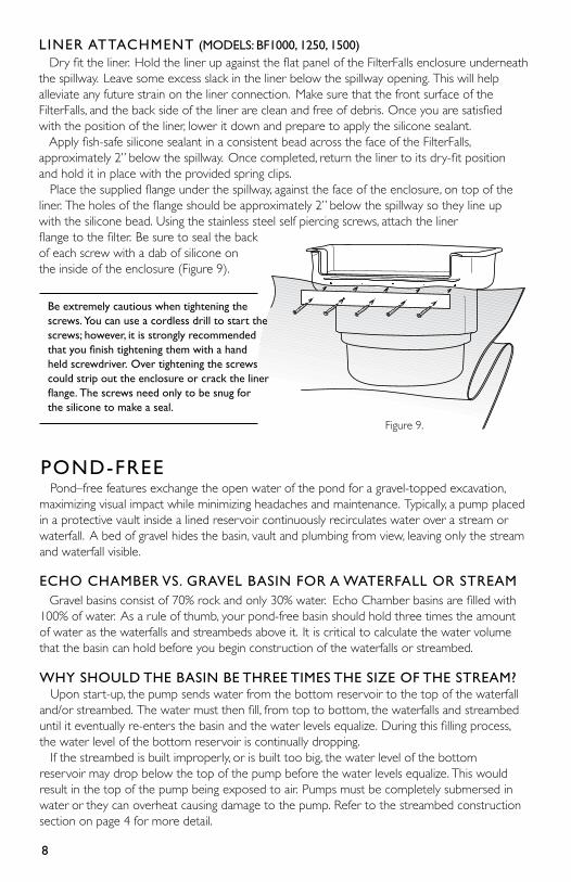
LINER ATTACHMENT (MODELS: BF1000, 1250, 1500) Dry fit the liner. Hold the liner up against the flat panel of the FilterFalls enclosure underneath the spillway. Leave some excess slack in the liner below the spillway opening. This will help alleviate any future strain on the liner connection. Make sure that the front surface of the FilterFalls, and the back side of the liner are clean and free of debris. Once you are satisfied with the position of the liner, lower it down and prepare to apply the silicone sealant. Apply fish-safe silicone sealant in a consistent bead across the face of the FilterFalls, approximately 2” below the spillway. Once completed, return the liner to its dry-fit position and hold it in place with the provided spring clips. Place the supplied flange under the spillway, against the face of the enclosure, on top of the liner. The holes of the flange should be approximately 2” below the spillway so they line up with the silicone bead. Using the stainless steel self piercing screws, attach the liner flange to the filter. Be sure to seal the back of each screw with a dab of silicone on the inside of the enclosure (Figure 9).
ECHO CHAMBER VS. GRAVEL BASIN FOR A WATERFALL OR STREAM Gravel basins consist of 70% rock and only 30% water. Echo Chamber basins are filled with 100% of water. As a rule of thumb, your pond-free basin should hold three times the amount of water as the waterfalls and streambeds above it. It is critical to calculate the water volume that the basin can hold before you begin construction of the waterfalls or streambed.
WHY SHOULD THE BASIN BE THREE TIMES THE SIZE OF THE STREAM? Upon start-up, the pump sends water from the bottom reservoir to the top of the waterfall and/or streambed. The water must then fill, from top to bottom, the waterfalls and streambed until it eventually re-enters the basin and the water levels equalize. During this filling process, the water level of the bottom reservoir is continually dropping. If the streambed is built improperly, or is built too big, the water level of the bottom reservoir may drop below the top of the pump before the water levels equalize. This would result in the top of the pump being exposed to air. Pumps must be completely submersed in water or they can overheat causing damage to the pump. Refer to the streambed construction section on page 4 for more detail.
Figure 9.
Be extremely cautious when tightening the screws. You can use a cordless drill to start the screws; however, it is strongly recommended that you finish tightening them with a hand held screwdriver. Over tightening the screws could strip out the enclosure or crack the liner flange. The screws need only to be snug for the silicone to make a seal.
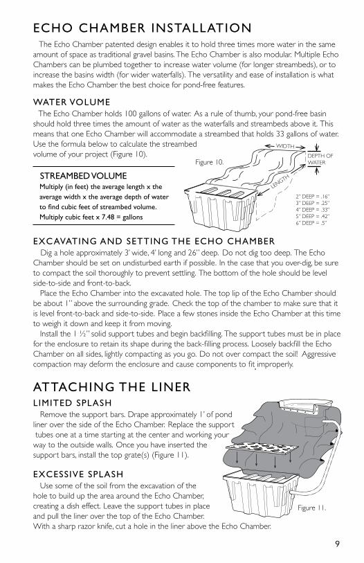
WATER VOLUME The Echo Chamber holds 100 gallons of water. As a rule of thumb, your pond-free basin should hold three times the amount of water as the waterfalls and streambeds above it. This means that one Echo Chamber will accommodate a streambed that holds 33 gallons of water. Use the formula below to calculate the streambed volume of your project (Figure 10).
STREAMBED VOLUME Multiply (in feet) the average length x the average width x the average depth of water to find cubic feet of streambed volume. Multiply cubic feet x 7.48 = gallons
EXCAVATING AND SETTING THE ECHO CHAMBER Dig a hole approximately 3’ wide, 4’ long and 26” deep. Do not dig too deep. The Echo Chamber should be set on undisturbed earth if possible. In the case that you over-dig, be sure to compact the soil thoroughly to prevent settling. The bottom of the hole should be level side-to-side and front-to-back. Place the Echo Chamber into the excavated hole. The top lip of the Echo Chamber should be about 1” above the surrounding grade. Check the top of the chamber to make sure that it is level front-to-back and side-to-side. Place a few stones inside the Echo Chamber at this time to weigh it down and keep it from moving. Install the 1 ½” solid support tubes and begin backfilling. The support tubes must be in place for the enclosure to retain its shape during the back-filling process. Loosely backfill the Echo Chamber on all sides, lightly compacting as you go. Do not over compact the soil! Aggressive compaction may deform the enclosure and cause components to fit improperly.
9
Figure 10.
ECHO CHAMBER INSTALLATION
The Echo Chamber patented design enables it to hold three times more water in the same amount of space as traditional gravel basins. The Echo Chamber is also modular. Multiple Echo Chambers can be plumbed together to increase water volume (for longer streambeds), or to increase the basins width (for wider waterfalls). The versatility and ease of installation is what makes the Echo Chamber the best choice for pond-free features.
WIDTHDEPTH OF WATER
LENGTH
2” DEEP = .16”3” DEEP = .25”4” DEEP = .33”5” DEEP = .42”6” DEEP = .5”
Figure 11.
ATTACHING THE LINER LIMITED SPLASH Remove the support bars. Drape approximately 1’ of pond liner over the side of the Echo Chamber. Replace the support tubes one at a time starting at the center and working your way to the outside walls. Once you have inserted the support bars, install the top grate(s) (Figure 11).
EXCESSIVE SPLASH Use some of the soil from the excavation of the hole to build up the area around the Echo Chamber, creating a dish effect. Leave the support tubes in place and pull the liner over the top of the Echo Chamber. With a sharp razor knife, cut a hole in the liner above the Echo Chamber.
10
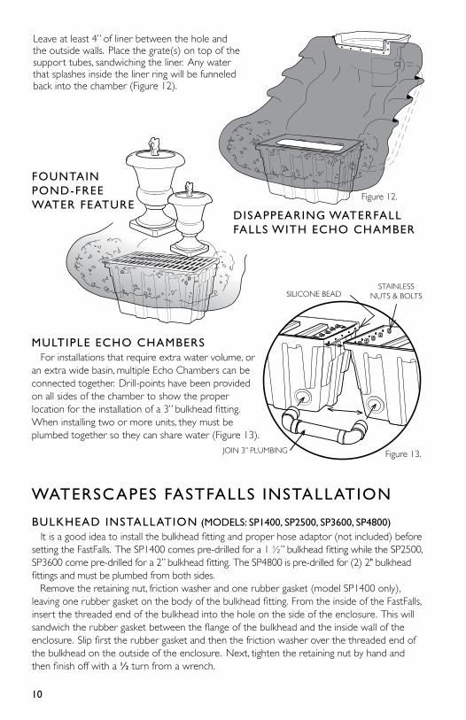
Leave at least 4” of liner between the hole and the outside walls. Place the grate(s) on top of the support tubes, sandwiching the liner. Any water that splashes inside the liner ring will be funneled back into the chamber (Figure 12).
MULTIPLE ECHO CHAMBERS For installations that require extra water volume, or an extra wide basin, multiple Echo Chambers can be connected together. Drill-points have been provided on all sides of the chamber to show the proper location for the installation of a 3” bulkhead fitting. When installing two or more units, they must be plumbed together so they can share water (Figure 13).
FOUNTAIN POND-FREE WATER FEATURE
WATERSCAPES FASTFALLS INSTALLATION BULKHEAD INSTALLATION (MODELS: SP1400, SP2500, SP3600, SP4800) It is a good idea to install the bulkhead fitting and proper hose adaptor (not included) before setting the FastFalls. The SP1400 comes pre-drilled for a 1 ½” bulkhead fitting while the SP2500, SP3600 come pre-drilled for a 2” bulkhead fitting. The SP4800 is pre-drilled for (2) 2" bulkhead fittings and must be plumbed from both sides. Remove the retaining nut, friction washer and one rubber gasket (model SP1400 only), leaving one rubber gasket on the body of the bulkhead fitting. From the inside of the FastFalls, insert the threaded end of the bulkhead into the hole on the side of the enclosure. This will sandwich the rubber gasket between the flange of the bulkhead and the inside wall of the enclosure. Slip first the rubber gasket and then the friction washer over the threaded end of the bulkhead on the outside of the enclosure. Next, tighten the retaining nut by hand and then finish off with a ½ turn from a wrench.
DISAPPEARING WATERFALL FALLS WITH ECHO CHAMBER
Figure 12.
JOIN 3” PLUMBING
SILICONE BEADSTAINLESS
NUTS & BOLTS
Figure 13.

Place the supplied flange under the spillway, against the face of the enclosure, on top of the liner. The holes of the flange should be approximately 2” below the spillway so they line up with the silicone bead. Using the stainless steel self piercing screws, attach the liner flange to the FastFalls. Be sure to seal the back of each screw with a dab of silicone on the inside of the enclosure (Figure 14).
11
Figure 14.
SETTING THE FASTFALLS It is always recommended that the FastFalls be placed on undisturbed soil if possible. If the installation calls for the FastFalls to be elevated above existing grade, it is critical to compact the area thoroughly. This will ensure that the FastFalls will not settle out of level over time. The FastFalls can be placed adjacent to the basin edge to create a single waterfall, or pulled away from the pond to create a streambed effect. Once you have placed the unit, make sure it is level from side-to-side and check the level from front-to-back. FastFalls should always be installed tilted slightly forward about ¼”. This will ensure that water never leaks out over the back of the enclosure.
LINER ATTACHMENT (SP1400, SP2500, SP3600, SP4800) Dry fit the liner. Hold the liner up against the flat panel of the FastFalls enclosure underneath the spillway. Leave some excess slack in the liner below the spillway opening. This will help alleviate any future strain on the liner connection. Make sure that the front surface of the FastFalls, and the back side of the liner, are clean and free of debris. Once you are satisfied with the position of the liner, lower it down and prepare to apply the silicone sealant. Apply fish-safe silicone sealant in a consistent bead across the face of the FastFalls, approximately 2” below the spillway. Once completed, return the liner to its dry-fit position and hold it in place with the provided spring clips. (Figure 14).
Be extremely cautious when tightening the screws. You can use a cordless drill to start the screws; however, it is strongly recommended that you finish tightening them with a hand held screwdriver. Over tightening the screws could strip out the enclosure or crack the liner flange. The screws need only to be snug for the silicone to make a seal.
Figure 13.

www.WAT E R S C A P E S I N T E R N AT I O N A L .com