application of passive uhf rfid in intermodal · pdf fileapplication of passive uhf rfid in...
TRANSCRIPT
Application of Passive UHF RFID inIntermodal Facilities
Daniel D. Deavours
ITTC-FY2010-TR-41420-14
July 2009
Copyright © 2009:The University of Kansas2335 Irving Hill Road, Lawrence, KS 66045-7559All rights reserved.
Project Sponsor:Oak Ridge National Laboratory
Technical Report
The University of Kansas
Page 1
Application of Passive UHF RFID in Intermodal Facilities Daniel D. Deavours
Information and Telecommunications Technology Center University of Kansas
2335 Irving Hill Road, Lawrence, KS 66047 [email protected]
Abstract In this paper, we explore the use of passive UHF RFID for tracking containers within intermodal facilities. We find that there are a number of emerging technologies that may be applicable, including the relatively new Mojix system and the KU Cargo Tag, a long range passive UHF RFID tag developed at the University of Kansas. We note that while there may be technical solutions available, the more challenging issue involves coordination and cooperation with the large number of companies and agencies that would benefit from such a system.
1. Introduction Automatic container-tracking within an intermodal facility may improve logistical efficiency and security. Passive UHF RFID is a potentially useful technology for tracking containers because of a unique combination of attributes, such as cost, performance, standardization, and adoption. An emerging, new capability within passive UHF RFID tag community is the ability to accurately identify the positioning of tags. This document reviews our findings on the suitability of using passive UHF RFID for intermodal facilities, and in particular on the applicability of location positioning capabilities within such an environment. Recently, there has been interest in the development of passive UHF RFID (pRFID) tags for intermodal containers. The rationales for using pRFID for intermodal containers are briefly as follows.
• Relatively long read distance allows automatic identification at range (30 feet or more). • Relatively low cost (few cents to dollars US). • The lack of an internal power supply reduces maintenance and extents life of the product
to approximately that of the life of the asset. • Compatible with ISO 18000-6c (“Gen 2”), which is becoming a very well-supported
standard. • Compatible with related EPCglobal information-sharing standards to associate containers
with pallets, cases, and items within those containers and to share that information across organizational boundaries.
• Weak but functional authentication through a combination of techniques, which gives reasonably strong pedigree verification. Techniques include:
o Use of unique tag ID (TID) within each IC that requires a foundry to replicate. o Password-protected portions of memory

Page 2
Because of these attributes, the use of pRFID may be a suitable technology for automatic tracking of containers. Some challenges of using the technology, briefly, are as follows.
• Typically relatively short read distance (only 30 feet or so) as compared to active RFID • Little intelligence / sensing / positioning • Lack of existing products for cargo containers • Lack of standardization, positive pilots, and proven business cases
While the above list is not exhaustive, they are probably the most notable. In this report, we aim to report on the current state of the technology to address the technical challenges, and we give comments on related business and policy challenges. The remainder of the report is outlined as follows. In Section 2, we give a further review of the pRFID technology to date, including ITTC/KU contributions, and emerging commercial products that provide location-positioning information. In Section 3, we give an overview of our observations of the technology in action. It was our aim to observe the technology used in use cases as similar as possible to those of an intermodal facility, but due to the newness of the technology and other constraints, that was not possible. However, we give a report on the technology’s capabilities as we observed them in the fall of 2008. In Section 4, we extrapolate our observations and knowledge of the pRFID system to pRFID may be used in an intermodal facility. Finally, we conclude with observations and thoughts on future directions.
2. Background
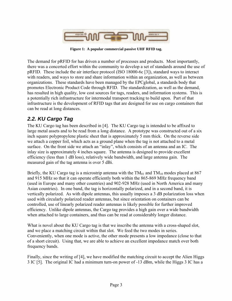
2.1. Passive UHF RFID Passive RFID is an old technology that has likely been used since WW-II [1]. Passive UHF RFID (hereafter pRFID), or RFID that specifically uses the frequency band between 860 and 960 MHz, has recently gained attention primarily because of retailer mandates [2], in which retailers are attempting to tag cases and pallets of products moving through the supply chain. pRFID transponders, or “tags,” are interrogated by interrogators or “readers.” The reader RF energy is used to power the tag (hence the tags are passive), interact with the tag according to a protocol, provide a clock, and to provide a carrier signal for the tag to backscatter information. The tags contain an integrated circuit (IC) which is used to decode the reader signal, store the tag ID in non-volatile RAM, and to backscatter the ID and other information. The tag also consists of an antenna, some carrier or encapsulation, and a method of attachment, such as pressure sensitive adhesive. The tag backscatters a signal by changing the impedance of the IC, which can change the magnitude and phase of the signal scattered (retransmitted) by the antenna. The hope within the supply chain industry is that increased product visibility will result in increases in efficiencies, such as reduced out-of-stocks, better logistical planning, anti-counterfeit measure, and reduced labor costs. UHF RFID was chosen because of a combination of low-cost ($0.10 per tag is now common) and relatively long read distance (25 feet is common), which will facilitate reading cases on a conveyor as well as cases and pallets moving through a dock door. Figure 1 shows a popular pRFID tag roughly to scale.
Page 3
Figure 1: A popular commercial passive UHF RFID tag.
The demand for pRFID for has driven a number of processes and products. Most importantly, there was a concerted effort within the community to develop a set of standards around the use of pRFID. These include the air interface protocol (ISO 18000-6c [3]), standard ways to interact with readers, and ways to store and share information within an organization, as well as between organizations. These standards have been managed by the EPCglobal, a standards body that promotes Electronic Product Code through RFID. The standardization, as well as the demand, has resulted in high quality, low cost sources for tags, readers, and information systems. This is a potentially rich infrastructure for intermodal transport tracking to build upon. Part of that infrastructure is the development of RFID tags that are designed for use on cargo containers that can be read at long distances.
2.2. KU Cargo Tag The KU Cargo tag has been described in [4]. The KU Cargo tag is intended to be affixed to large metal assets and to be read from a long distance. A prototype was constructed out of a six inch square polypropylene plastic sheet that is approximately 5 mm thick. On the reverse side we attach a copper foil, which acts as a ground plane when the tag is not attached to a metal surface. On the front side we attach an “inlay”, which consists of an antenna and an IC. The inlay size is approximately 4 inches square. The antenna is designed to provide excellent efficiency (less than 1 dB loss), relatively wide bandwidth, and large antenna gain. The measured gain of the tag antenna is over 5 dBi. Briefly, the KU Cargo tag is a microstrip antenna with the TM01 and TM10 modes placed at 867 and 915 MHz so that it can operate efficiently both within the 865-869 MHz frequency band (used in Europe and many other countries) and 902-928 MHz (used in North America and many Asian countries). In one band, the tag is horizontally polarized, and in a second band, it is vertically polarized. As with dipole antennas, this usually imposes a 3 dB polarization loss when used with circularly polarized reader antennas, but since orientation on containers can be controlled, use of linearly polarized reader antennas is likely possible for further improved efficiency. Unlike dipole antennas, the Cargo tag provides a high gain over a wide bandwidth when attached to large containers, and thus can be read at considerably longer distance. What is novel about the KU Cargo tag is that we inscribe the antenna with a cross-shaped slot, and we place a matching circuit within that slot. We feed the two modes in series. Conveniently, when one mode is active, the other mode presents a low impedance (close to that of a short circuit). Using that, we are able to achieve an excellent impedance match over both frequency bands. Finally, since the writing of [4], we have modified the matching circuit to accept the Alien Higgs 3 IC [5]. The original IC had a minimum turn-on power of -13 dBm, while the Higgs 3 IC has a

Page 4
stated turn-on power of approximately -18 dBm, which yields more than 5 dB of performance improvement over [4].
Figure 2: The KU Cargo tag.
The KU Cargo tag designed for the Higgs 3 IC, shown in Figure 2, was tested by a third party in a warehouse environment with a circularly polarized reader antenna. Note that this environment provided considerable ground, ceiling, and other sources of reflection. We observed reliable reads out to approximately 80 feet and intermittent reads to about 100 feet. From about 110 to 120 feet, the tag was not readable likely because it was in a local null zone. At about 130 feet, the tag became readable intermittently. The long read distance was likely assisted by multi-path effects in the warehouse environment.

Page 5
2.3. Portunus RFID Tag The Portunus RFID tag [6] (see Figure 3) was designed to operate in a heavy industrial environment. The requirement was to have a low profile, be very rugged, and it was acceptable to compromise read distance for other requirements. The Portunus tag was developed by the University of Kansas RFID Lab to meet this market requirement. The Portunus tag is two by four inches square and uses a 1/16” polycarbonate substrate. The IC is protected by being placed in a small recess in the polycarbonate. Again, the inlay is affixed to the front of the substrate and a copper foil to the reverse side of the substrate. More information about the technology used to develop the RFID tag is given in [7].
Figure 3: Early version of the Portunus RFID tag. Photo by Megan E. Gannon.
The Portunus RFID tag is currently being used to tag metal assets for use in rugged environments, such as manufacturing. The largest application is installation on farm equipment at the time of manufacturing. Since the Portunus tag is commercially available, it was used for some of the location-positioning testing.
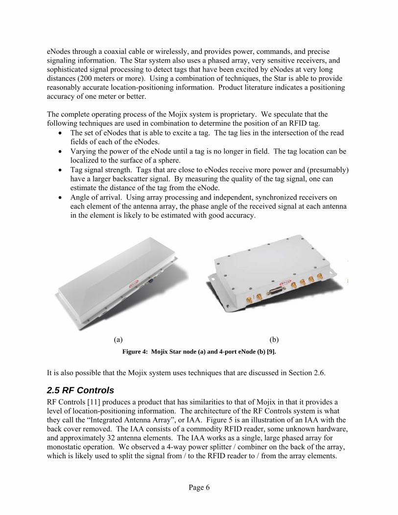
2.4. Mojix In traditional pRFID systems, the readers emit RF energy fields, and tags within the field respond. The reader performs the transmitting and receiving functions, i.e., a transceiver, either by using two isolated antennas (bistatic), or electrically splitting the transmit and receive signals from a single antenna (monostatic). Readers are relatively self-contained, typically having a considerable amount of local computing resources to run local applications, but also capable of communicating to middleware or back-end systems through a network. To instrument a large facility with RFID, it takes a large number of readers, each covering a relatively small localized zone. While some readers are becoming smarter and capable of some positioning or sensing capabilities, such is a direction of travel through a portal or sensing a tag is getting closer or further away, location positioning is dominated by presence or absence in read zones and travel through choke points. These capabilities are of little use in intermodal facilities. The Mojix system [8] differs from the classical system in a number of ways. First, the hardware performing transmit and receive function are physically separated. The transmit function is performed a low-cost “eNode” [9] (see Figure 4b). The receive function over a large area is concentrated in a single (or small number) of “Star” nodes [10] (see Figure 4a), which contain a phased array antenna and sophisticated signal processing capabilities. The Star node controls the
Page 6
eNodes through a coaxial cable or wirelessly, and provides power, commands, and precise signaling information. The Star system also uses a phased array, very sensitive receivers, and sophisticated signal processing to detect tags that have been excited by eNodes at very long distances (200 meters or more). Using a combination of techniques, the Star is able to provide reasonably accurate location-positioning information. Product literature indicates a positioning accuracy of one meter or better. The complete operating process of the Mojix system is proprietary. We speculate that the following techniques are used in combination to determine the position of an RFID tag.
• The set of eNodes that is able to excite a tag. The tag lies in the intersection of the read fields of each of the eNodes.
• Varying the power of the eNode until a tag is no longer in field. The tag location can be localized to the surface of a sphere.
• Tag signal strength. Tags that are close to eNodes receive more power and (presumably) have a larger backscatter signal. By measuring the quality of the tag signal, one can estimate the distance of the tag from the eNode.
• Angle of arrival. Using array processing and independent, synchronized receivers on each element of the antenna array, the phase angle of the received signal at each antenna in the element is likely to be estimated with good accuracy.
(a) (b)
Figure 4: Mojix Star node (a) and 4-port eNode (b) [9].
It is also possible that the Mojix system uses techniques that are discussed in Section 2.6.
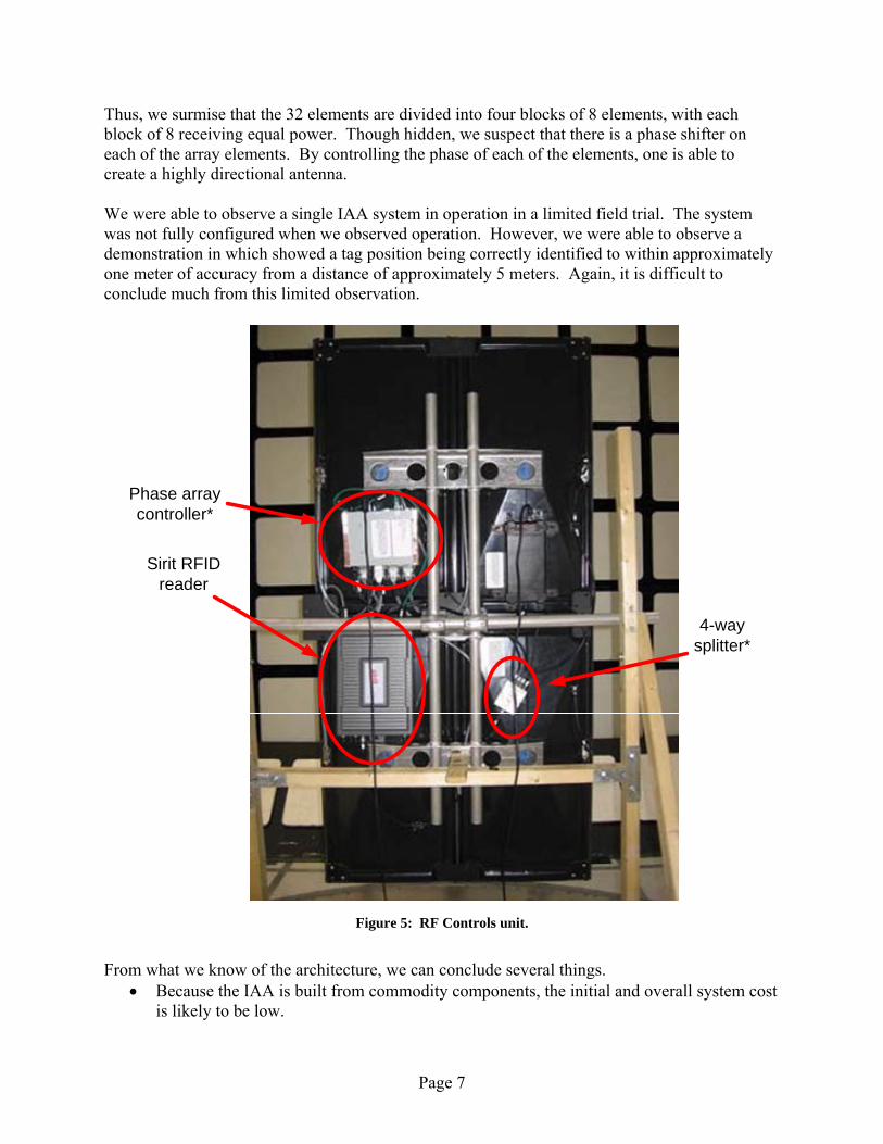
2.5 RF Controls RF Controls [11] produces a product that has similarities to that of Mojix in that it provides a level of location-positioning information. The architecture of the RF Controls system is what they call the “Integrated Antenna Array”, or IAA. Figure 5 is an illustration of an IAA with the back cover removed. The IAA consists of a commodity RFID reader, some unknown hardware, and approximately 32 antenna elements. The IAA works as a single, large phased array for monostatic operation. We observed a 4-way power splitter / combiner on the back of the array, which is likely used to split the signal from / to the RFID reader to / from the array elements.
Page 7
Thus, we surmise that the 32 elements are divided into four blocks of 8 elements, with each block of 8 receiving equal power. Though hidden, we suspect that there is a phase shifter on each of the array elements. By controlling the phase of each of the elements, one is able to create a highly directional antenna. We were able to observe a single IAA system in operation in a limited field trial. The system was not fully configured when we observed operation. However, we were able to observe a demonstration in which showed a tag position being correctly identified to within approximately one meter of accuracy from a distance of approximately 5 meters. Again, it is difficult to conclude much from this limited observation.
Sirit RFID reader
4-way splitter*
Phase array controller*
Figure 5: RF Controls unit.
From what we know of the architecture, we can conclude several things.
• Because the IAA is built from commodity components, the initial and overall system cost is likely to be low.
Page 8
• Because the system is inherently monostatic, one complete IAA system will need to be installed for each area to be monitored.
• By overlapping read zones, one is able to increase the positioning accuracy of the system, but with a proportionate increase in cost.
• A RF Controls representative indicated that positioning was likely to be inaccurate at distance and in heavy multi-path environments.
• The phased array is physically large, approximately 4 by 8 feet. This makes it impractical for many outdoor environments where wind load will be an issue.
The economics of the RF Controls and Mojix system differs. The IAA is likely to have a lower initial cost, but will scale more poorly. The Mojix system, because of the cost of the Star receiver, will have a high initial cost. Adding additional eNodes are likely to be much less expensive. Neither RF Controls nor Mojix were willing to provide any pricing information outside of a confidentiality agreement.
2.6. Advanced Research in Location Positioning in Multi-Path Environments A recent article [12] described some of the most advanced research in location positioning in a multi-path environment. We briefly describe the approach that we investigated here. The premise of this approach is that the receiver uses a phased array that is very well characterized and calibrated. Second, it is assumed that the signal from the transmitter has a limited (20 kHz) bandwidth, which is comparable to signal bandwidth used in RFID systems. The system uses a combination of both the estimated angle of arrival and the signal correlation coefficient to estimate whether two signals that are received from different angles are in fact the same signal. Within an RFID system, the question is not whether the signal is emitted from two different sources or the same source; a collision detection algorithm within the protocol can be used for that purpose. The difference in a Mojix-like system is that the system is coherent: the tag’s signal is the modulated reflected signal from an eNode, which is under direct and presumably coherent control from the Star node. Thus, it may be possible to use a coherent match filter and the angle of arrival to reinforce the estimate of a distinct multi-path. Further, the matched filter can be used to estimate the path length of each incident signal. If one is able to correctly estimate all the multi-paths and the length of each path, then one may be able to estimate the distance of the shortest path. The distance and angle of arrival of the shortest distance, if line-of-sight is one of the paths, is sufficient to estimate the location of a tag. Failing that, one may be able to estimate the angle and distance of the dominant signal. Again, the estimate would assume the dominant signal is the line-of-sight signal, and that a multi-path signal is attenuated. As with any FCC-compliant device, the RFID reader system uses frequency hopping over the 902-928 MHz frequency band, so tags may be interrogated multiple times on different channels in order to obtain a more reliable estimate. Finally, for stationary or slow-moving objects, repeated observations may be used to increase the confidence of various estimates.
Page 9
We emphasize that we have no knowledge about whether the Mojix system uses this or any similar approach to estimating positioning. We are merely inferring that existing research results of [12] with modifications may be applied to a Mojix-like system for local positioning.
3. Observations Here, we report on our observations of the Mojix system used for evaluation of commercial fitness for a number of use cases. We are somewhat limited in what we are able to report due to sensitivity of the companies involved.
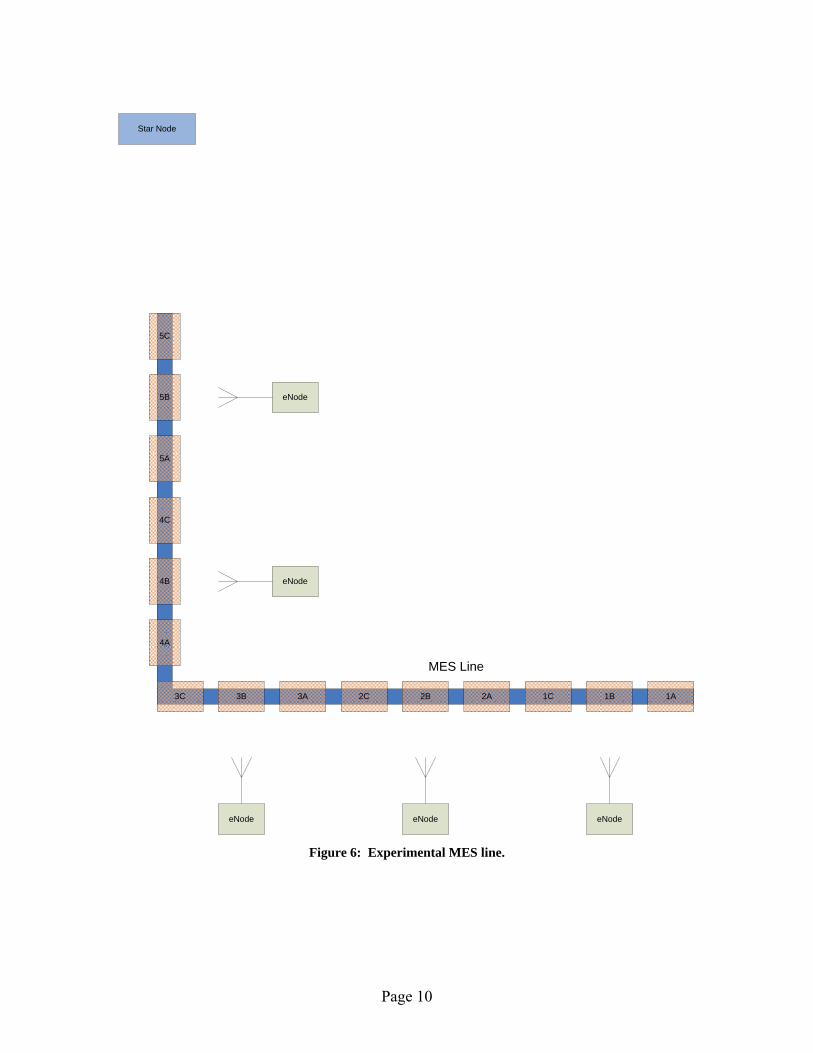
3.1. Manufacturing and Execution System (MES) We observed Mojix operational in a MES (manufacturing and execution system, i.e., an assembly line) use case. Figure 6 illustrates the MES setup that was tested. We observed two use cases. First, a metal rack on wheels was tagged with a KU Portunus RFID tag. The metal rack was pulled through five stations. At each station, the rack was placed in three positions: early, middle, and late within the station, labeled A, B, and C respectively. At each point in the station, the Mojix system attempted to identify the station that the rack was in, and in which position of each station. The experiment was repeated five times. We observed that for all five experiments, the Mojix system was able to correctly identify the station and position within the station with every attempt. The second use case involved two metal racks, both tagged using a KU Portunus tag. The two racks were exactly one station apart. For example, the first rack was in 1A and the second rack was in 2A, then the first rack was moved to 1B and the second rack to 2B, etc. The experiment was repeated five times. Again, the Mojix system was able to correctly identify the station and position of each rack in all five of the experiments. We speculate that the method in which the Mojix system is estimating the rack position is by determining the eNodes that are able to excite the Portunus tags and the signal strength of each of the tags as excited by different eNodes, and perhaps by varying the eNode transmit power. For example, a rack at position 1B could be read by eNode 1 on very low power levels. In position 1C, eNode 1 would require more power to read the tag, while eNode 2 may be able to read the tag at very high power levels.
Page 10
Star Node
MES Line
1A1B1C2A2B2C3A3B3C
eNode eNode eNode
eNode
eNode
4A
4B
4C
5A
5B
5C
Figure 6: Experimental MES line.

Page 11
3.2. Dock Door Application Next, the Mojix system was used to identify pallets coming in and out of a dock door onto a truck. Two dock doors were instrumented with eNodes and photo sensors. The test was to determine if the Mojix system could correctly identify the pallet tag ID and the door that the pallet would enter or exit while being carried by a fork lift. The test setup was less formal, and was performed relatively quickly based on time constraints. We observed that the Mojix system was able to correctly identify the dock door and the pallet tag on every test case. This test seems somewhat contrived, since there was only one lift truck operational, and there were photo sensors on both of the eNodes. Simply correlating the reads with the photo sensor would be sufficient for the system to correctly correlate the reads with the dock door. Thus, this test demonstrated no unique capability of the Mojix system. In private discussions with Mojix representatives, Mojix claims that their system is capable of detecting the contents of pallets on fork lifts traveling through as many as eight dock doors simultaneously. We have no way of verifying this claim, nor do we have any reason to doubt its validity. This form of location-positioning offers little technical advantage over the capability of current fixed reader systems, but it was a successful demonstration.
3.3. Real Time Location Positioning (RTLS) Next, we observed the Mojix system acting in a RTLS tracking mode in tracking a single RFID tag. This proved problematic. The team spent two days troubleshooting the system, and the system never fully functioned properly. Debriefing with Mojix representatives, we understand that there were some configuration difficulties and challenges working across time zones, and that Mojix did not understand that this would be a tested use case and therefore the system was not configured to perform that test. Regardless, here are our general observations.
• The RTLS system took several seconds to identify the region and provide an <X,Y> coordinate for the system. Once it did, the system appeared to be fairly accurate, i.e., within three to five feet, sometimes more accurate.
• If the tag moved, the RTLS system would take several seconds to recognize the move, and the measured position would slowly converge to the new position over several more seconds. After debriefing with Mojix, we understand that this was an intentional delay filter that was inserted because of the previous tests involving tracking racks required accuracy of slow-moving objects.
• The RTLS did not appear to be able to accurately track a tag moving at the pace of a brisk walk, or any motion that involved several abrupt changes in direction. After debriefing with Mojix, it is their claim that the system is capable of providing that capability, but the test that we observed was not properly configured for that use case. We have no evidence to confirm or reason to refute this claim.

Page 12
3.4. Large Container Stationing This example is very similar to the use of ISO containers in an intermodal facility. In this example, the KU Cargo tag was attached to a large metal container. While these were not ISO containers, there were similarly sized and used in a similar manner. The particular application studied here is to manage large containers in a staging yard. The yard is 150 feet wide and contains numerous containers that are moved by heavy equipment. Within this 150 zone, no RFID equipment is allowed. The application is to track the container assets within the yard. Assets may be at most 75 feet from one of the sides of the yard, and thus there is a tag read distance requirement of 75 feet. In this experiment, the KU Cargo tag using the Higgs 3 IC was affixed to a container and the Mojix system was used to track the location of the container within the yard. The KU Cargo / Higgs 3 tag was used because of the long read distance requirement. To maximize performance, the Mojix eNodes should use linearly polarized antennas, since the KU Cargo tag is linearly polarized. This experiment was found to be satisfactory using circularly polarized eNode antennas. The Mojix system was deployed around the perimeter of the yard to provide location-positioning information. Figure 7 illustrates the setup. We are able to give only high-level observations of the results. We can say that the Mojix system was able to reasonably predict the location of RFID tags within the staging area and with reasonable accuracy and timeliness. We generally conclude that with line-of-sight, the Mojix system is likely to be able to detect with reasonable accuracy the position of a container in a yard.

Page 13
No Reader Zone
container
container
container
container
container
container
container
container
container
container
container
container
container
container
container
container
eNode eNode eNode eNode
eNode eNode eNode eNode
Star Node
Star Node
150'
Figure 7: Example of experimental test scenario for large metal container storage and staging area.
4. Applicability to Intermodal Facilities We were not able to directly test the ability to tag and track containers in intermodal facilities. This is due to relatively new technology and great sensitivity from potential early adopters to protect potential trade secrets. However, we have seen the product perform in several environments, have interacted with representatives, and can discuss potential capabilities. We note the following observations:

Page 14
• As claimed [13], the Star node is extremely sensitive. It was able to detect the KU Cargo tag at nearly 130 feet away when the Star was pointing away from the tag. Thus, the signal from the tag was very weak, and the Star node must have detected the signal from one or more reflections, further weakening the signal.
• We observed location-positioning capabilities that were not highly refined and took some time to settle on a location, but likely due to in part to improper configuration. Regardless, it showed location positioning accuracy sufficient to one to two meters, which is more than sufficient for locating a container in a storage yard. Similarly positive results from the container staging area are positive indicators of likely usability.
• The wireless eNode released in October 2008, which we did not observe, potentially adds flexibility to the exciters. It is not clear whether the wireless eNodes can be mobile and still provides accurate location positioning, or whether it is a feature that could be added in the future. If so, a mobile eNode could be used inventory and position containers within the yard periodically.
• The KU Cargo tag provided excellent long-distance performance. IC improvement has been growing steadily so that read distances double every 2 to 3 years. There is evidence that this trend can continue for at least one more generation of chips before efficiencies are exhausted and performance becomes more closely tied to Moore’s law. However, recent trends indicate that additional improvements will be focused on decreasing costs more than increasing IC sensitivity, so it might be the case that the next generation of ICs will provide more features and lower cost rather than improved performance.
Within an intermodal facility, we envision two possible use cases. The first is to observe the container any time it is moved, and the second is to observe the container as it is stationary. Both provide different use cases and potential business benefits. All loading and moving equipment would be fitted with a powered eNode, which would be able to excite RFID tags attached to containers at is being moved. All truck and rail chokepoints would also be fitted with powered eNodes and sensors. One or two Star nodes would be fitted within a facility that would provide coverage and greater accuracy in triangulation. In this way, all movement of containers within the facility could be directly monitored with a system like the Mojix RTLS and supplemented through other forms of data acquisition, such as manual data entry. With the wireless eNode, these use cases become readily feasible. Static monitoring is useful to detect unauthorized or erroneous movement of containers within the facility. This can be very helpful, for example, in finding “lost” containers. For this application, one could fit normal operating equipment with a wireless eNode, which would move throughout the yard in normal operations, and in doing so, would assist in monitoring location information of the containers in the yard. In addition, a periodic yard “audit” could be performed by one of the vehicles to validate the yard inventory. These methods would allow the excitation of RFID tags potentially deep within container “canyons.” Without direct line-of-sight, location-positioning is not likely to be highly accurate. However, accuracy of this use case is not critical; it would be sufficiently accurate to detect whether a container is not close to where it is supposed to be, or is absent. Anomalous container movement could be detected relatively quickly, and still protected by chokepoints.
Page 15
While use of RFID and location services is useful for yard management, more value can be obtained through better logistics management. Knowing when and where containers were offloaded could provide better end-to-end logistics management. For example, if a container is not off-loaded at the proper port (perhaps because it was improperly loaded), the sooner the information is known, the easier it is for logistics providers and down-stream consumers to make adjustments. Second, by using the authentication features of the ISO 18000-6c standard, one can perform better and more targeted container inspections. By having reasonably strong authentication and methods of sharing data, together with manifest information, one can easily identify containers that come from trusted sources through secure ports and those that do not. This will allow port security to target those containers that are at much higher risk. It is our opinion that pRFID will not be implemented on containers without a mandate and some clear, industry-wide, over-arching plan. Because of the number of organizations, both private and government, the data sharing, sharing cost, maintenance, deployment standardization, and numerous other issues, it is unlikely that such an integrated system would arise organically in the near future. This is a common challenge with using RFID as infrastructure: the benefits are spread across numerous organizations, but the costs are often concentrated to a few organizations. Equitably sharing costs and benefits can be an insurmountable challenge without a single dominant advocate. It is our opinion that technical solutions exist or can be easily developed in the near future to meet the technical requirements. The most significant problem is finding ways to incentivize organizations to work together to exploit the efficiencies in the system that are available.
5. Conclusions In this report, we examine the use of passive RFID and location positioning within an intermodal facility. We find that the most promising technology is a combination of a system like the Mojix system and the KU Cargo tag or similar high gain antenna tag. We observed an early Mojix system demonstration that showed a combination of great potential and the challenges that are common with new systems: awkward configuration process, organizations unwilling to share information early on, and poor early-stage support. For example, the KU Cargo tag shows excellent capabilities, but is not yet commercially available primarily due to weak demand. We believe that the obstacles are part of the “growing pains” of an early-stage technology, but our opinion, there are no technical hurdles that are not insurmountable. We foresee that the largest hurdle will be the cross-organizational will to deploy such a system.
Page 16
References [1] Daniel M. Dobkins. The RF in RFID. Newness, 2008. [2] “Wal-Mart Expands RFID Mandate,” RFID Journal, August 18, 2003, available
http://www.rfidjournal.com/article/view/539/1/1. [3] International Organization for Standards, “Information technology – radio frequency
identification for item management – part 6: Parameters for air interface communications at 860 MHz to 960 MHz,” ISO/IEC, Tech. Rep. 18000-6:2004/Amd 1:2006, 2006.
[4] Supreetha Aroor and Daniel D. Deavours, Dual-Resonant Microstrip-Based UHF RFID
Cargo" Tag. In Proc. IEEE MTT-S International Microwave Symposium 2008 (IMS2008) June 15-20, 2008, Atlanta, TX.
[5] “Alien Higgs 3 Product Overview,” Alien Technologies, June, 2008, available
http://www.alientechnology.com/docs/products/DS_H3.pdf. [6] Starport Technologies, “Products – Portunus | Starport Technologies,”
http://starporttech.com/products/portunus.html, accessed November 20, 2008. [7] M. Eunni, M. Sivakumar, D. D. Deavours. A Novel Planar Microstrip Antenna Design
for UHF RFID. JSCI, vol. 5, no. 1, January 2007, pp. 6-10. [8] Mojix. http://www.mojix.com/ [9] Mojix, “Mojix eNode Family,” product brochure, 2008, available
http://www.mojix.com/products/documents/Mojix_eNode_Brochure.pdf. [10] Mojix, “Mojix Star System,” product brochure, 2008, available
http://www.mojix.com/products/documents/Mojix_STAR_System.pdf. [11] RF Controls home page, available http://www.rfctrls.com/ [12] Uğur Sarac, F. Kerem Harmanci, and Tayfun Akgül, "Experimental Analysis of
Detection and Localization of Multiple Emitters in Multipath Environments,” IEEE Antennas and Propagation Magazine, Vol. 50, No. 5, October 2008.
[13] Andy Holman, personal communications, November 2008.