application manual - dreamtime universityapplication manual . mechanical application. many swarovski...
TRANSCRIPT
P—
14
4.1
45

20
17/18
7A
PP
LICA
TION
MA
NU
AL
MECHANICAL APPLICATION
Many Swarovski products, such as Snap Fasteners, Rivets, and Rose Pins can be applied manually or mechanically, using either semi- or fully-automated machines. This simple application technique is used primarily in the textile and accessories fields.
146 Product Overview146 Machines and Tools159 Suppliers164 Application182 Useful Information183 Quick Assistance

P—
14
6.1
47
M E C H A N I C A L A P P L I C A T I O N
PRODUCT OVERVIEW
The following products are suitable for mechanical application:
MACHINES AND TOOLS
The following machines and tools can be used for the mechanical application of Swarovski products:
PR
OD
UC
T O
VE
RV
IEW
& M
AC
HIN
ES
AN
D T
OO
LS
The fly press (art. 9040/019, with mounting board) represents an easy way to mechanically apply the products.
Some Swarovski products can be applied using a semi- or fully-automatic attaching machine (e.g. Rose Pins). In this process, the feed on the machine must be adjusted to the product being processed.
Vacuum pump (art. 9040/022) with silicone hose allows products such as Rivets and Pins to be easily held in place for the fly press .
BUTTONS & FASTENERS MECHANICAL APPLICATION
Snap Fasteners, Decorative Buttons and XIRIUS Flat Back Snap Fastener �
Jeans Buttons �
METAL TRIMMING MECHANICAL APPLICATION
Standard Rivets, Square Rivets, Star Rivet, Spike Rivets and Rivet Flat Shaft �
Rose Pins and Rhombus Pin �
Crystal Studs �
3D Studs �

20
17/18
7
AP
PLIC
ATIO
N M
AN
UA
L
It is recommended that protective eyewear is worn during mechanical application, to prevent injury.
For application of Rose Pins a Rose Pin mold can be used (patented by Gruppo Meccaniche Luciani). Please be advised that Swarovski does not provide the tools.
3D Studs can be applied using a 3D Stud mold (offered by Gruppo Meccaniche Luciani). Please be advised that Swarovski does not provide the tools for this mold.
Swarovski offers a variety of dif ferent tools for the fly press, depending on the product employed. The tools offered have
the following specifications: upper die (M6 screw thread), lower die (12.15 mm + 0.03/– 0.10).
If using a fly press from a provider other than Swarovski, confirm the thread sizes before ordering the tools.
Vacuum pump
Vacuum adapter
Silicone hose for vacuum pump
Stop
Lower die
Upper die
Mounting board
Fly press including possible dies and tools for application (in this case for the application of Rivets).

P—
14
8.1
49
M E C H A N I C A L A P P L I C A T I O NM
AC
HIN
ES
AN
D T
OO
LS
1780/100 Snap Fastener
Requ
ired
App
licat
ion
Tool
s
Upper Die Lower Die
Art. 9060/005 Art. 9060/004
Art. 9060/006 Art. 9060/007
1780/114 Snap Fastener
Requ
ired
App
licat
ion
Tool
s
Upper Die Lower Die
Art. 9060/005 Art. 9060/004
Art. 9060/006 Art. 9060/007
Both Snap Fasteners and Decorative Buttons are applied using a fly press.
While the Decorative Button is only used for decorative purposes,
the Snap Fastener comes with the additional closing function.
1781/100 Decorative Button
Requ
ired
App
licat
ion
Tool
s
Upper Die Lower Die
Art. 9060/005 Art. 9060/004
1781/114 Decorative Button
Requ
ired
App
licat
ion
Tool
s
Upper Die Lower Die
Art. 9060/005 Art. 9060/004
SNAP FASTENERS AND DECORATIVE BUTTONS
20
17/18
7
AP
PLIC
ATIO
N M
AN
UA
L XIRIUS FLAT BACK SNAP FASTENER
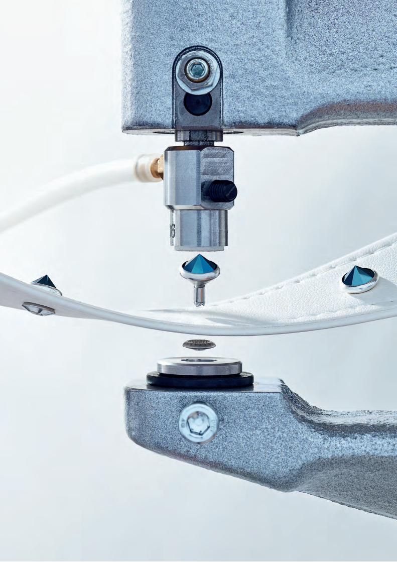
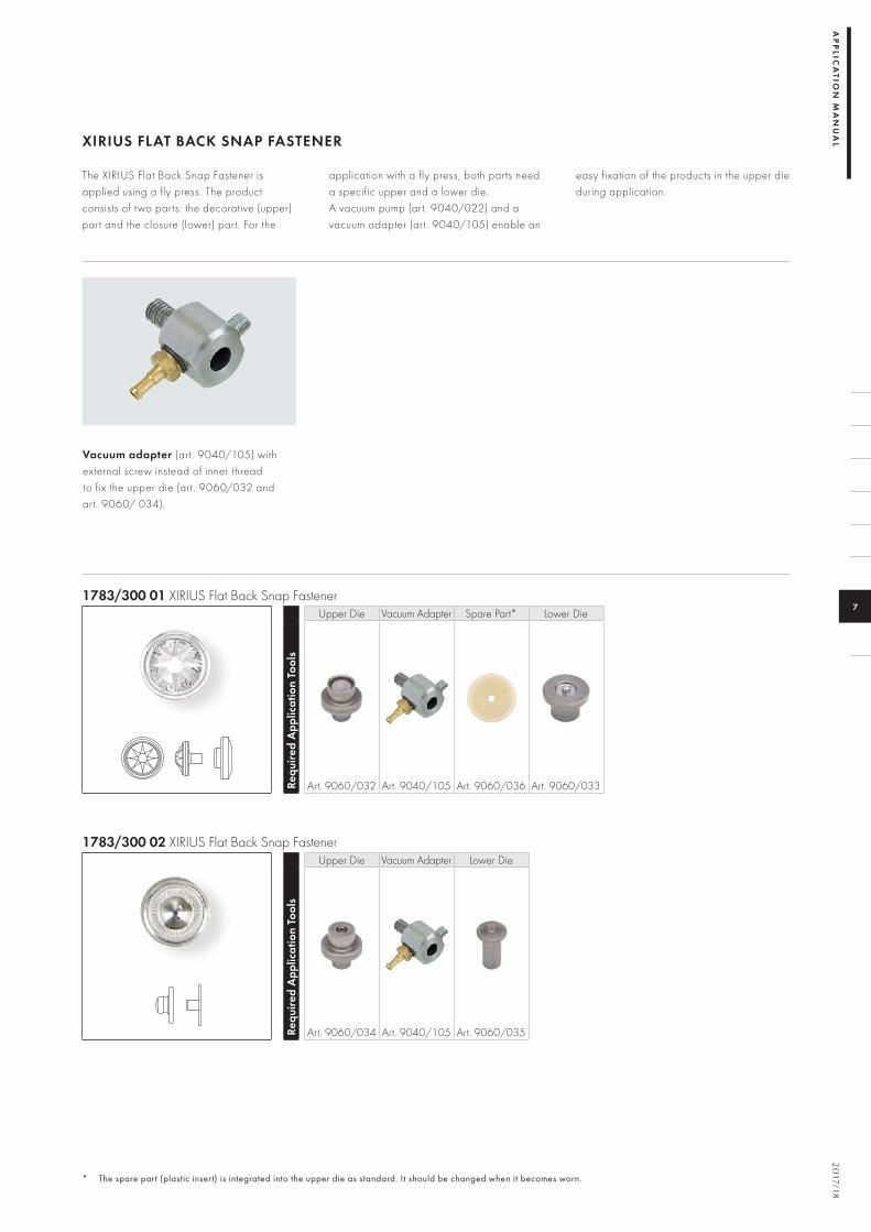
The XIRIUS Flat Back Snap Fastener is applied using a fly press. The product consists of two parts: the decorative (upper) part and the closure (lower) part. For the
application with a fly press, both parts need a specific upper and a lower die. A vacuum pump (art. 9040/022) and a vacuum adapter (art. 9040/105) enable an
easy fixation of the products in the upper die during application.
Vacuum adapter (art. 9040/105) with external screw instead of inner thread to fix the upper die (art. 9060/032 and art. 9060/ 034).
1783/300 01 XIRIUS Flat Back Snap Fastener
Requ
ired
App
licat
ion
Tool
s
Upper Die Vacuum Adapter Spare Part* Lower Die
Art. 9060/032 Art. 9040/105 Art. 9060/036 Art. 9060/033
* The spare part (plastic insert) is integrated into the upper die as standard. It should be changed when it becomes worn.
1783/300 02 XIRIUS Flat Back Snap Fastener
Requ
ired
App
licat
ion
Tool
s
Upper Die Vacuum Adapter Lower Die
Art. 9060/034 Art. 9040/105 Art. 9060/035

P—
15
0.1
51
M E C H A N I C A L A P P L I C A T I O N
1 The appropriate thread adapter is supplied with the fly press art. 9040/017 and art. 9040/019.
2 Holder for plastic insert (spare part). The plastic insert for the upper die (art. 9060/009) must be ordered separately depending on the type of button it will be used with.
3 Insert for upper die.
MA
CH
INE
S A
ND
TO
OL
S
JEANS BUTTONS
1790/100 Jeans Button
Requ
ired
App
licat
ion
Tool
s
Upper Die Lower Die Thread Adapter1
Art. 9060/001 Art. 9060/016Art. 9060/014
(M6)
1790/104 Jeans Button
Requ
ired
App
licat
ion
Tool
s
Upper Die2 Spare Part3 Lower Die Thread Adapter1 Changing Pin
Art. 9060/009 Art. 9060/011 Art. 9060/016Art. 9060/014
(M6) Art. 9060/015Tool Set
Art. 9060/020
1790/114 Jeans Button
Requ
ired
App
licat
ion
Tool
s
Upper Die Lower Die Thread Adapter1
Art. 9060/001 Art. 9060/016Art. 9060/014
(M6)

20
17/18
7
AP
PLIC
ATIO
N M
AN
UA
L
1 Holder for plastic insert (spare part). The plastic insert for the upper die (art. 9060/009) must be ordered separately depending on the type of button it will be used with.
2 Insert for upper die.
3 The appropriate thread adapter is supplied with the fly press art. 9040/017 and art. 9040/019.
1790/140 Jeans Button
Requ
ired
App
licat
ion
Tool
s
Upper Die1 Spare Part2 Lower Die Thread Adapter3 Changing Pin
Art. 9060/009 Art. 9060/010 Art. 9060/016Art. 9060/014
(M6) Art. 9060/015Tool Set
Art. 9060/020
1795/140 Crystal Fine Rocks Jeans Button
Requ
ired
App
licat
ion
Tool
s
Upper Die1 Spare Part2 Lower Die Thread Adapter3 Changing Pin
Art. 9060/009 Art. 9060/018 Art. 9060/016Art. 9060/014
(M6) Art. 9060/015Tool Set
Art. 9060/020
1797/140 Crystal Fabric Jeans Button
Requ
ired
App
licat
ion
Tool
s
Upper Die1 Spare Part2 Lower Die Thread Adapter3 Changing Pin
Art. 9060/009 Art. 9060/018 Art. 9060/016Art. 9060/014
(M6) Art. 9060/015Tool Set
Art. 9060/020

P—
15
2.1
53
Art. 9040/023
M E C H A N I C A L A P P L I C A T I O N
Rivets can be applied to various materials with or without Back Parts. The correct die combination must be chosen accordingly. Please ensure that the recommended fabric strengths, listed in the “Application”
subsection, are followed. A vacuum pump and adapter allow Rivets to be easily picked up and applied. Upper dies are thus available with dif ferent thread strengths. When using the Swarovski
vacuum adapter, dies with an M8 thread are required. Alternatively, dies with M6 threads are available for presses from other manufacturers, or when not using a vacuum adapter.
RIVETS
MA
CH
INE
S A
ND
TO
OL
S
Requ
ired
App
licat
ion
Tool
s
Upper Die Vacuum Adapter1
Spare Part for Upper Die
(insert)2
Lower Die for application with
Back Part:
Lower Die for application with
Back Part:
Lower Die for application
without Back Part for Rivet
casing color 088 Stainless
Steel
Lower Die for application
without Back Part for Rivet casing color 081 Gold
082 Silver086 Gun Metal093 Rose Gold53 007 53 009
Art. 9070/010 Art. 9070/012 Art. 9070/011 Art. 9040/015
53 000
Art. 9040/005 M8 Art. 9040/023
Art. 9040/008Art. 9040/014
M6 –SS 18
53 001
Art. 9070/005 M8 Art. 9040/023
Art. 9070/008Art. 9070/009
M6 –SS 29
53 002
Art. 9040/005 M8 Art. 9040/023
Art. 9040/008Art. 9040/014
M6 –SS 18 (short shank)
53 005
Art. 9040/064 M8 Art. 9040/023
Art. 9040/062Art. 9040/063
M6 –SS 34
53 006
Art. 9040/067 M8 Art. 9040/023
Art. 9040/065Art. 9040/066
M6 –SS 39
53 008
Art. 9040/083 M8 Art. 9040/023
Art. 9040/084Art. 9040/085
M6 –PP 24
1 When using Swarovski's fly press, tools with M8 thread and the corresponding vacuum adapter are necessary.
2 The spare part (plastic insert) is incorporated into the upper die as standard. It should be changed when it becomes worn.

20
17/18
7
Art. 9040/105
AP
PLIC
ATIO
N M
AN
UA
L
1 When using Swarovski's fly press, tools with M8 thread and the corresponding vacuum adapter are necessary.
2 The spare part (plastic insert) is incorporated into the upper die as standard. It should be changed when it becomes worn.
Requ
ired
App
licat
ion
Tool
s
Upper Die Vacuum Adapter1
Spare Part for Upper Die
(insert)2
Lower Die for application with
Back Part:
Lower Die for application with
Back Part:
Lower Die for application
without Back Part for Rivet
casing color 088 Stainless
Steel
Lower Die for application
without Back Part for Rivet casing color 081 Gold
082 Silver086 Gun Metal093 Rose Gold53 007 53 009
Art. 9070/010 Art. 9070/012 Art. 9070/011 Art. 9040/015
53 500
Art. 9040/106 Art. 9040/105 –
4 mm
53 501
Art. 9040/107 Art. 9040/105 –
6 mm
53 502
Art. 9040/108 Art. 9040/105 –
8 mm
53 700
Art. 9040/112 Art. 9040/105 Art. 9040/113
10 mm
53 010
Art. 9040/123 Art. 9040/105 Art. 9040/124
SS 29
53 011
Art. 9040/125 Art. 9040/105 Art. 9040/126
SS 39
53 503
Art. 9040/127 Art. 9040/105 Art. 9040/128
8 mm

P—
15
4.1
55
M E C H A N I C A L A P P L I C A T I O NM
AC
HIN
ES
AN
D T
OO
LS
RIVET FLAT SHAFT
For the application of the Rivet Flat Shaft no Back Part is necessary. This reduces the distance between fabric and Rivet and ensures a flat surface on the rear side.
1 The spare part (plastic insert) is incorporated into the upper die as standard. It should be changed when it becomes worn.
2 Rivet Flat Shaft 53 003 is designed for ring rolling application and is self-backing. The Rivet can be applied on either an automatic or semi-automatic machine
or with a fly press. For application with fly press, use the lower die art. 9070/010 without Back Part.
53 003 Rivet (SS 29 flat shaft) Re
quire
d A
pplic
atio
n To
ols
Upper Die Vacuum Adapter
Spare Part for Upper Die
(insert)¹
Lower Die2
Art. 9070/005 M8 Art. 9040/023 Art. 9070/008 Art. 9070/010
Beside applying the Rivet Flat Shaft with fly press, this article can also be applied using an automatic attaching machine.
Please note: Lower die (art. 9070/010) was updated in autumn 2014. The new version can be used for all Rivet applications the former tool version was used for. However, please consider that for new Rivets such as the Rivet Flat Shaft, only the optimized version of the tool can be used. If a lower die with article number 9070/010 was bought before October 2014 the tool must be replaced in order to apply the Rivet Flat Shaft successfully.
A vacuum pump and a vacuum adapter (art. 9040/023) enable easy intake and application of the Rivet Flat Shaft. Generally, it is recommended to apply this Rivet only on non-elastic fabrics like jeans or leather with a material thickness of 2 – 3.5 mm.

20
17/18
7
AP
PLIC
ATIO
N M
AN
UA
L ROSE PINS
A vacuum pump allows Rose Pins to be easily picked up and applied. The vacuum connection is integrated directly into the upper die. An additional vacuum adapter is not necessary.
Please note: All Rose Pin spare parts have been adapted in summer 2017. They look slightly dif ferent now while making it easier to replace the spare part in the upper die.
53 301 Rose Pin (SS 10) Re
quire
d A
pplic
atio
n To
ols
Upper Die Spare Part¹ Lower Die Centering Aid2
Art. 9040/090 M6 Art. 9040/094 Art. 9070/013 Art. 9070/017
53 302 Rose Pin (SS 16)
Requ
ired
App
licat
ion
Tool
s
Upper Die Spare Part¹ Lower Die
Art. 9040/091 M6 Art. 9040/095 Art. 9070/014
53 303 Rose Pin (SS 20)
Requ
ired
App
licat
ion
Tool
s
Upper Die Spare Part¹ Lower Die
Art. 9040/092 M6 Art. 9040/096 Art. 9070/014
53 304 Rose Pin (SS 34)
Requ
ired
App
licat
ion
Tool
s
Upper Die Spare Part¹ Lower Die
Art. 9040/093 M6 Art. 9040/097 Art. 9070/016
1 The spare part (plastic insert) is integrated into
the upper die as standard. It should be changed
when it becomes worn.
2 The centering aid (art. 9070/017)
for Rose Pin 53 301 allows the product to be
easily positioned in the upper die.

P—
15
6.1
57
M E C H A N I C A L A P P L I C A T I O NM
AC
HIN
ES
AN
D T
OO
LS
Specially developed vacuum adapter (art. 9040/105) with external screw instead of thread to fix the upper die.
53 320 Rhombus Pin (10x6 mm)
Requ
ired
App
licat
ion
Tool
s
Upper Die Vacuum Adapter
Spare Part¹ Lower Die Centering Aid²
Art. 9040/116 Art. 9040/105 Art. 9040/119 Art. 9070/021 Art. 9070/022
RHOMBUS PIN
Rhombus Pins can be easily applied to various materials by using a fly press. A vacuum pump (art. 9040/022) and a
vacuum adapter (art. 9040/105) enable an easy intake and application of the Pins.
1 The spare part (plastic insert) is integrated into the upper die as standard. It should be changed when it becomes worn.
2 The centering aid (art. 9070/022) for Rhombus Pin 53 320 allows the product to be easily positioned in the upper die.
20
17/18
7
AP
PLIC
ATIO
N M
AN
UA
L
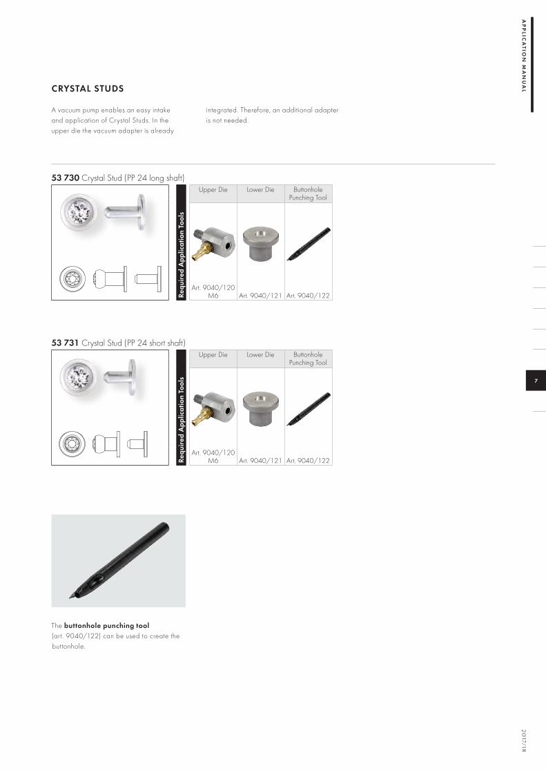
The buttonhole punching tool (art. 9040/122) can be used to create the buttonhole.
CRYSTAL STUDS
A vacuum pump enables an easy intake and application of Crystal Studs. In the upper die the vacuum adapter is already
integrated. Therefore, an additional adapter is not needed.
53 730 Crystal Stud (PP 24 long shaft) Re
quire
d A
pplic
atio
n To
ols
Upper Die Lower Die ButtonholePunching Tool
Art. 9040/120 M6 Art. 9040/121 Art. 9040/122
53 731 Crystal Stud (PP 24 short shaft)
Requ
ired
App
licat
ion
Tool
s
Upper Die Lower Die ButtonholePunching Tool
Art. 9040/120 M6 Art. 9040/121 Art. 9040/122

P—
15
8.1
59
54 001
54 002
54 003
M E C H A N I C A L A P P L I C A T I O NM
AC
HIN
ES
AN
D T
OO
LS
& S
UP
PL
IER
S
3D STUDS
For the application with the fly press, the following tools can be used. Please consider that a vacuum pump (art. 9040/022) is
necessary to hold the Back Part in place. The vacuum connection is integrated directly into the upper die.
Requ
ired
App
licat
ion
Tool
s
Upper Die Insert Insert Insert Lower Die Linear Grid* Changing Pin
Art. 9060/040 Art. 9060/041 Art. 9060/042 Art. 9060/043 Art. 9060/044 Art. 9060/045 Art. 9060/015
4 mm
6 mm
8 mm
* Optional tool for the even/linear application of more than one 3D Stud.

20
17/18
7
AP
PLIC
ATIO
N M
AN
UA
L SUPPLIERS
This list provides an overview of selected suppliers worldwide.
MACHINES & TOOLS SUPPLIER CONTACT
Fly press Swarovski:Fly press without mounting board: art. 9040/017Fly press with mounting board: art. 9040/019Jiuzhou Machinery Co., Ltd. Seung Min Industrial Co., Ltd.Standard Rivet Company
www.swarovski-professional.com
www.sinojiuzhou.com www.seungminsm.co.krwww.standardrivet.com
Tools for Snap Fasteners (fly press)
Swarovski:Snap Fastener 1780/100 and 1780/114Upper die: art. 9060/005 (1st stage) and art. 9060/006 (2nd stage)Lower die: art. 9060/004 (1st stage) and art. 9060/007 (2nd stage)
www.swarovski-professional.com
Tools for Decorative Buttons (fly press)
Swarovski:Decorative Button 1781/100 and 1781/114 Upper die: art. 9060/005Lower die: art. 9060/004
www.swarovski-professional.com
Tools for XIRIUS Flat Back Snap Fasteners (fly press)
Swarovski:XIRIUS Flat Back Snap Fastener 1783/300Vacuum adapter for upper dies: art. 9040/105Upper die for decorative part (art. 1783/300 01): art. 9060/032Spare part (plastic insert) for upper die (art. 9060/032): art. 9060/036Lower die for decorative part (art. 1783/300 01): art. 9060/033Upper die for closure part (art. 1783/300 02): art. 9060/034Lower die for closure part (art. 1783/300 02): art. 9060/035
www.swarovski-professional.com
Tools for Jeans Buttons (fly press)
Swarovski:Jeans Button 1790/100 and 1790/114Upper die: art. 9060/001Lower die: art. 9060/016Thread adapter (M6): art. 9060/014
www.swarovski-professional.com
Jeans Button 1790/104Upper die: art. 9060/009Spare part (plastic insert) for upper die: art. 9060/011Lower die: art. 9060/016Thread adapter (M6): art. 9060/014Changing pin: art. 9060/015
Jeans Button 1790/140Upper die: art. 9060/009Spare part (plastic insert) for upper die: art. 9060/010Lower die: art. 9060/016Thread adapter (M6): art. 9060/014Changing pin: art. 9060/015
Crystal Fine Rocks Jeans Button 1795/140 and Crystal Fabric Jeans Button 1797/140Upper die: art. 9060/009Spare part (plastic insert) for upper die: art. 9060/018Lower die: art. 9060/016Thread adapter (M6): art. 9060/014Changing pin: art. 9060/015
All tools as set for Jeans Button 1790/104, 1790/140, Crystal Fine Rocks Jeans Button 1795/140 and Crystal Fabric Jeans Button 1797/140: art. 9060/020

P—
16
0.1
61
M E C H A N I C A L A P P L I C A T I O NS
UP
PL
IER
S
MACHINES & TOOLS SUPPLIER CONTACT
Tools for Rivets (fly press) Swarovski: Rivet 53 000Upper die (M8): art. 9040/005Upper die (M6): art. 9040/014Spare part (plastic insert) for upper die (art. 9040/005 and 9040/014): art. 9040/008Lower die for Rivet application with Back Part 53 007: art. 9070/010Lower die for Rivet application with Back Part 53 009: art. 9070/012Lower die for Rivet application without Back Part (Rivet casing 081, 082 and 086): art. 9040/015Lower die for Rivet application without Back Part (Rivet casing 088): art. 9070/011Vacuum adapter for upper die (art. 9040/005): art. 9040/023
www.swarovski-professional.com
Rivet 53 001Upper die (M8): art. 9070/005Upper die (M6): art. 9070/009Spare part (plastic insert) for upper die (art. 9070/005 and 9070/009): art. 9070/008Lower die for Rivet application with Back Part 53 007: art. 9070/010Lower die for Rivet application with Back Part 53 009: art. 9070/012Lower die for Rivet application without Back Part (Rivet casing 081, 082 and 086): art. 9040/015Lower die for Rivet application without Back Part (Rivet casing 088): art. 9070/011Vacuum adapter for upper die (art. 9070/005): art. 9040/023
Rivet 53 002Upper die (M8): art. 9040/005Upper die (M6): art. 9040/014Spare part (plastic insert) for upper die (art. 9040/005 and 9040/014): art. 9040/008Lower die for Rivet application without Back Part (Rivet casing 081, 082 and 086): art. 9040/015Vacuum adapter for upper die (art. 9040/005): art. 9040/023
Rivet 53 005Upper die (M8): art. 9040/064Upper die (M6): art. 9040/063Spare part (plastic insert) for upper die (art. 9040/064 and 9040/063): art. 9040/062Lower die for Rivet application with Back Part 53 007: art. 9070/010Lower die for Rivet application with Back Part 53 009: art. 9070/012Lower die for Rivet application without Back Part (Rivet casing 081, 082 and 086): art. 9040/015Lower die for Rivet application without Back Part (Rivet casing 088): art. 9070/011Vacuum adapter for upper die (art. 9040/064): art. 9040/023
Rivet 53 006Upper die (M8): art. 9040/067Upper die (M6): art. 9040/066Spare part (plastic insert) for upper die (art. 9040/067 and 9040/066): art. 9040/065Lower die for Rivet application with Back Part 53 007: art. 9070/010Lower die for Rivet application with Back Part 53 009: art. 9070/012Lower die for Rivet application without Back Part (Rivet casing 081, 082 and 086): art. 9040/015Lower die for Rivet application without Back Part (Rivet casing 088): art. 9070/011Vacuum adapter for upper die (art. 9040/067): art. 9040/023

20
17/18
7
AP
PLIC
ATIO
N M
AN
UA
L
MACHINES & TOOLS SUPPLIER CONTACT
Rivet 53 008Upper die (M8): art. 9040/083Upper die (M6): art. 9040/085Spare part (plastic insert) for upper die (art. 9040/083 and 9040/085): art. 9040/084Lower die for Rivet application with Back Part 53 009: art. 9070/012Lower die for Rivet application without Back Part (Rivet casing 088): art. 9070/011Vacuum adapter for upper die (art. 9040/083): art. 9040/023
Tools for Square Rivets (fly press)
Swarovski: Square Rivet 53 500Upper die: art. 9040/106Lower die for Rivet application with Back Part 53 007: art. 9070/010Lower die for Rivet application with Back Part 53 009: art. 9070/012Lower die for Rivet application without Back Part (Rivet casing 081, 082 and 086): art. 9040/015Lower die for Rivet application without Back Part (Rivet casing 088): art. 9070/011Vacuum adapter for upper die: art. 9040/105
www.swarovski-professional.com
Square Rivet 53 501Upper die: art. 9040/107Lower die for Rivet application with Back Part 53 007: art. 9070/010Lower die for Rivet application with Back Part 53 009: art. 9070/012Lower die for Rivet application without Back Part (Rivet casing 081, 082 and 086): art. 9040/015Vacuum adapter for upper die: art. 9040/105
Square Rivet 53 502Upper die: art. 9040/108Lower die for Rivet application with Back Part 53 007: art. 9070/010Lower die for Rivet application with Back Part 53 009: art. 9070/012Lower die for Rivet application without Back Part (Rivet casing 081, 082 and 086): art. 9040/015Vacuum adapter for upper die: art. 9040/105
Tools for Star Rivets (fly press) Swarovski: Star Rivet 53 700Upper die: art. 9040/112Spare part (plastic insert) for upper die (art. 9040/112): art. 9040/113Lower die for Rivet application with Back Part 53 007: art. 9070/010Lower die for Rivet application with Back Part 53 009: art. 9070/012Lower die for Rivet application without Back Part (Rivet casing 081, 082 and 086): art. 9040/015Vacuum adapter for upper die: art. 9040/105
www.swarovski-professional.com
Tools for Spike Rivets (fly press)
Swarovski: Spike Rivet 53 010Upper die: art. 9040/123Spare part (plastic insert) for upper die (art. 9040/123): art. 9040/124Lower die for Rivet application with Back Part 53 007: art. 9070/010Lower die for Rivet application with Back Part 53 009: art. 9070/012Lower die for Rivet application without Back Part (Rivet casing 081, 082 and 086): art. 9040/015Vacuum adapter for upper die: art. 9040/105
www.swarovski-professional.com

P—
16
2.1
63
M E C H A N I C A L A P P L I C A T I O NS
UP
PL
IER
S
MACHINES & TOOLS SUPPLIER CONTACT
Spike Rivet 53 011Upper die: art. 9040/125Spare part (plastic insert) for upper die (art. 9040/125): art. 9040/126Lower die for Rivet application with Back Part 53 007: art. 9070/010Lower die for Rivet application with Back Part 53 009: art. 9070/012Lower die for Rivet application without Back Part (Rivet casing 081, 082 and 086): art. 9040/015Vacuum adapter for upper die: art. 9040/105
Spike Rivet 53 503Upper die: art. 9040/127Spare part (plastic insert) for upper die (art. 9040/127): art. 9040/128Lower die for Rivet application with Back Part 53 007: art. 9070/010Lower die for Rivet application with Back Part 53 009: art. 9070/012Lower die for Rivet application without Back Part (Rivet casing 081, 082 and 086): art. 9040/015Vacuum adapter for upper die: art. 9040/105
Tools for Rivets Flat Shaft(fly press)
Swarovski:Rivet Flat Shaft 53 003Upper die (M8): art. 9070/005Spare part (plastic insert) for upper die (art. 9070/005): art. 9070/008Lower die for Rivet application without Back Part: art. 9070/010Vaccuum adapter for upper die: art. 9040/023
www.swarovski-professional.com
Tools for Rose Pins (fly press) Swarovski:Rose Pin 53 301Upper die (M6): art. 9040/090Spare part (plastic insert) for upper die (art. 9040/090): art. 9040/094Lower die: art. 9070/013Centering aid: art. 9070/017
www.swarovski-professional.com
Rose Pin 53 302Upper die (M6): art. 9040/091Spare part (plastic insert) for upper die (art. 9040/091): art. 9040/095Lower die: art. 9070/014
Rose Pin 53 303Upper die (M6): art. 9040/092Spare part (plastic insert) for upper die (art. 9040/092): art. 9040/096Lower die: art. 9070/014
Rose Pin 53 304Upper die (M6): art. 9040/093Spare part (plastic insert) for upper die (art. 9040/093): art. 9040/097Lower die: art. 9070/016

20
17/18
7
AP
PLIC
ATIO
N M
AN
UA
L
MACHINES & TOOLS SUPPLIER CONTACT
Tools for Rhombus Pins (fly press)
Swarovski: Rhombus Pin 53 320Upper die: art. 9040/116Spare part (plastic insert) for upper die (art. 9040/116): 9040/119Lower die: art. 9070/021Centering aid: art. 9070/022Vacuum adapter for upper die: art. 9040/105
www.swarovski-professional.com
Tools for Crystal Studs (fly press)
Swarovski:Crystal Stud 53 730 and 53 731Buttonhole punching tool: art. 9040/122Upper die (M6): art. 9040/120Lower die: art. 9040/121
www.swarovski-professional.com
Tools for 3D Studs (fly press)
Swarovski:3D Stud 54 001Upper die for Back Part 54 004: art. 9060/040Insert: art. 9060/041Lower die: art. 9060/044Linear grid: art. 9060/045Changing pin: art. 9060/015
www.swarovski-professional.com
3D Stud 54 002Upper die for Back Part 54 004: art. 9060/040Insert: art. 9060/042Lower die: art. 9060/044Linear grid: art. 9060/045Changing pin: art. 9060/015
3D Stud 54 003Upper die for Back Part 54 004: art. 9060/040Insert: art. 9060/043Lower die: art. 9060/044Linear grid: art. 9060/045Changing pin: art. 9060/015
Vacuum pump with silicone hose
Swarovski: art. 9040/022 www.swarovski-professional.com
Automatic attaching machine Jiuzhou Machinery Co., Ltd. Prym Fashion GmbHSeung Min Industrial Co., Ltd.Sagitta SPA
www.sinojiuzhou.com www.prym-fashion.com www.seungminsm.co.krwww.sagitta.it
Rose Pin mold Gruppo Meccaniche Luciani Srl www.gruppomeccanicheluciani.com
3D Stud mold Gruppo Meccaniche Luciani Srl www.gruppomeccanicheluciani.com

P—
16
4.1
65
M E C H A N I C A L A P P L I C A T I O NA
PP
LIC
AT
ION
C H E C K I N G M A T E R I A L S T R E N G T H
C H E C K I N G M A T E R I A L S T R E N G T H
P R O D U C T - S P E C I F I C A P P L I C A T I O N
P R O D U C T - S P E C I F I C A P P L I C A T I O N
APPLICATION
Various Swarovski products can be applied using mechanical force, creating a lasting bond with the carrier material.
CHECKING MATERIAL STRENGTH
PRODUCT-SPECIFIC APPLICATION
SNAP FASTENERS AND DECORATIVE BUTTONS
To apply Snap Fasteners and Decorative Buttons with a fly press, first fix the required dies into place in the fly press. A Decorative Button is the upper part of a Snap Fastener, which is applied purely
for decorative purposes and thus does not require a closure. When applying Snap Fasteners, a second stage is required in order to fix the closure in place.
Please note the material thickness when selecting Snap Fasteners and Decorative Buttons.
It is important to carefully check the thickness of the fabric or leather before beginning the application process. With very thick fabrics, a hole can be punched beforehand for the application of Jeans Buttons and Rivets. The fabric should
not crinkle or become gathered after application. To check this, carry out tests on fabric or leather scraps before going ahead with the application process. It is also important to make sure that the die sits straight and firmly in the fly press, as this
can often cause application problems. It is recommended that you carry out a few test runs to identify the ideal pressure. The offset/pressure can be regulated using an adjustable stop that is fastened to the handle of the fly press.
* This can vary according to the roughness and production of the carrier material.
ART. SIZE MATERIAL THICKNESS*
SNAP FASTENERS 1780/1001780/114
11 mm11 mm
1 – 3 mm1 – 3 mm
DECORATIVE BUTTONS 1781/1001781/114
11 mm11 mm
1 – 3 mm1 – 3 mm

20
17/18
7
AP
PLIC
ATIO
N M
AN
UA
L
C H E C K I N G M A T E R I A L S T R E N G T H P R O D U C T - S P E C I F I C A P P L I C A T I O N
Stage 1: Decorative Button/upper part of Snap Fastener
Upper die
Lower die
Decorative Button/upper part of Snap Fastener
Spring socket
1 Place the Decorative Button/upper part of the Snap Fastener in the lower die, with the claws pointing upwards.
2 Place the spring socket in the upper die. 3 Apply the product to the textile in the previously marked position. Regulate the offset/pressure using the adjustable stop.
Note: To make finding the right application position easier, it can be marked prior to the application. Therefore place the textile on an eraser and put the Decorative Button / upper part of the Snap Fastener on top of it (with claws pointing downwards). Press the Button into the textile. The material is marked while the eraser prevents the claws from getting destroyed.

P—
16
6.1
67
M E C H A N I C A L A P P L I C A T I O NA
PP
LIC
AT
ION
C H E C K I N G M A T E R I A L S T R E N G T H P R O D U C T - S P E C I F I C A P P L I C A T I O N
Stage 2: Snap Fastener closure
Upper die
Lower die
Pronged ring
Ball part
1 Place the pronged ring in the lower die, with the prongs pointing upwards.
2 Place the ball part in the upper die. 3 Apply the product to the textile in the pre- viously marked position, ensuring it is on the right side of the fabric. Regulate the offset/pressure using the adjustable stop.

20
17/18
7
AP
PLIC
ATIO
N M
AN
UA
L
C H E C K I N G M A T E R I A L S T R E N G T H P R O D U C T - S P E C I F I C A P P L I C A T I O N
XIRIUS FLAT BACK SNAP FASTENER
XIRIUS Flat Back Snap Fasteners can be easily applied using a fly press. The application is divided into two steps as the
product consists of two parts (decorative part and closure).
It is important to carefully check and to consider the thickness of the fabric before beginning the application process.
ART. SIZE MATERIAL THICKNESS*
XIRIUS FLAT BACK SNAP FASTENER 1783/300 7 mm 1.4 – 3.0 mm
* This can vary according to the roughness and production of the carrier material.
Before starting, make sure the fly press is aligned and upper and lower dies are arranged along an axis. Dies should be clean, polished and intact.
By carrying out pre-application tests, contracted or crinkled material after the application can be avoided, as well as too much space between fabric and pieces.
In order to prevent possible injury, the wearing of protective eyewear is recommended when mechanically applying crystal products.
If tools (fly press, dies) are not precisely adjusted, the following problems might occur:— The pieces could come off if they are not
correctly applied— Space between the fabric and the
applied pieces— Damages of the fabric
Before starting the application make sure that upper and lower die are positioned in the center. Pre-punching the fabric and positioning it properly on top of the lower die guarantees the correct functionality of the finished product.

P—
16
8.1
69
M E C H A N I C A L A P P L I C A T I O N
Stage 2: Application of the closure (lower) part
1 Replace the upper and lower die in order to apply the Snap Fastener closure.
2 Place the ball part in the upper die (will be kept in position by vacuum) and the counterpart in the lower die.
3 Apply the product on the carrier material. Adjust the offset/pressure using the adjustable stop.
Check the functionality of the Snap Fastener after the application.
AP
PL
ICA
TIO
N
C H E C K I N G M A T E R I A L S T R E N G T H P R O D U C T - S P E C I F I C A P P L I C A T I O N
Stage 1: Application of the decorative (upper) part
1 Place the vacuum adapter and the tools in the fly press. Make sure that they are fixed and connect the vacuum adapter to vacuum pump.
2 Place the decorative part in the upper die and the spring socket in the lower die. The vacuum will keep the decorative part in upper position during application.
3 Apply the product on the carrier material. Adjust the offset/pressure using the adjustable stop.

20
17/18
7
AP
PLIC
ATIO
N M
AN
UA
L
C H E C K I N G M A T E R I A L S T R E N G T H P R O D U C T - S P E C I F I C A P P L I C A T I O N
1 To change the insert according to the Swarovski products used, you will need the changing pin and the new plastic insert.
2 Use the changing pin to slowly slide the plastic insert out of the attaching die from above, through the small hole at the edge.
3 Press the new plastic insert into the attaching die right up to the top.
Changing the plastic insert
JEANS BUTTONS
To apply Jeans Buttons, first fix the required dies into place in the fly press. When applying Jeans Buttons
1790/104, 1790/140 and 1797/140 the corresponding plastic insert has to be changed.
Please note the material thickness when selecting Jeans Buttons.
* This can vary according to the roughness and production of the carrier material.
ART. SIZE MATERIAL THICKNESS*
JEANS BUTTONS 1790/1001790/1041790/1141790/1401795/1401797/140
14 mm17 mm14 mm17 mm17 mm17 mm
1 – 3 mm1 – 3 mm1 – 3 mm1 – 3 mm1 – 3 mm1 – 3 mm
P—
17
0.1
71
M E C H A N I C A L A P P L I C A T I O NA
PP
LIC
AT
ION
C H E C K I N G M A T E R I A L S T R E N G T H P R O D U C T - S P E C I F I C A P P L I C A T I O N
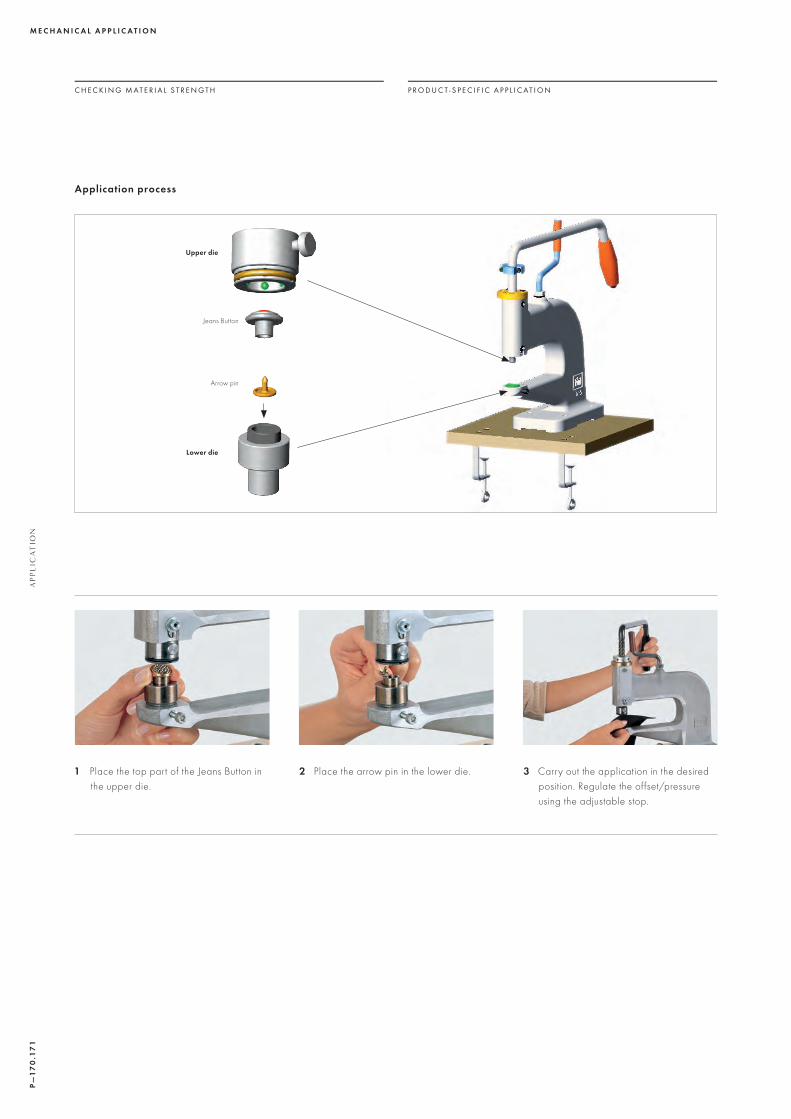
1 Place the top part of the Jeans Button in the upper die.
2 Place the arrow pin in the lower die. 3 Carry out the application in the desired position. Regulate the offset/pressure using the adjustable stop.
Application process
Upper die
Lower die
Arrow pin
Jeans Button

20
17/18
7
AP
PLIC
ATIO
N M
AN
UA
L
RIVETS
For the application of Rivets, use a fly press or a semi-automatic attaching machine: The following instructions focus on the application with the fly press. As a first step, attach the appropriate die to the fly press. Rivets can be applied on various materials
with or without Back Parts. Rivet 53 002 and Rivet Flat Shaft 53 003 are specially designed for application without a Back Part. For applications on leather, Stainless Steel Rivets (color code 088) and Back Parts are recommended.
Please note the material thickness when selecting Rivets. The dies should be selected accordingly.
1 This can vary according to the roughness and production of the carrier material.
2 Rivet Flat Shaft 53 003 is designed for ring rolling application and is self-backing. The Rivet can be applied on either an automatic or semi-automatic machine
or with a fly press. For application with fly press, use the lower die art. 9070/010 without Back Part.
ART. SIZE MATERIAL THICKNESS¹ POSSIBLE BACK PARTS
RIVETS 53 00053 00153 00253 00553 00653 008
SS 18SS 29SS 18SS 34SS 39PP 24
2.0 – 2.5 mm2.0 – 2.5 mm1.5 – 2.0 mm2.0 – 2.5 mm2.2 – 2.7 mm1.5 – 2.0 mm
53 007 and 53 009 53 007 and 53 009
53 007 and 53 009 53 007 and 53 009 53 009
RIVET FLAT SHAFT² 53 003 SS 29 2.0 – 3.5 mm
SQUARE RIVETS 53 50053 50153 502
4 mm6 mm8 mm
2.0 – 2.5 mm2.0 – 2.5 mm2.2 – 2.7 mm
53 007 and 53 00953 007 and 53 00953 007 and 53 009
STAR RIVET 53 700 10 mm 1.5 – 3.0 mm 53 007 and 53 009
SPIKE RIVETS 53 01053 01153 503
SS 29SS 398 mm
2.0 – 3.0 mm2.0 – 3.0 mm2.0 – 3.0 mm
53 007 and 53 00953 007 and 53 00953 007 and 53 009
C H E C K I N G M A T E R I A L S T R E N G T H P R O D U C T - S P E C I F I C A P P L I C A T I O N

P—
17
2.1
73
M E C H A N I C A L A P P L I C A T I O NA
PP
LIC
AT
ION
Application with a fly press
In many cases it is possible to select between both versions of the Back Part. For applications on thinner fabrics, it is better to use the larger Back Part (art. 53 007). Its size means this Back Part
can better hold the split Rivet shaft, avoiding any damage to the crystal.
For multi-layered or thicker materials, the smaller Back Part (art. 53 009) can be used.
To create a lasting bond, this requires less space for the split Rivet shaft. If the carrier material proves too thick, or is made up of several layers, it is recommended to punch a hole before application.
Upper die
Rivet
Back Part
Lower die
with Back Part without Back Part for Rivet casing color
081, 082, 086
without Back Partfor Rivet casing color 088
ROSE PINS AND RHOMBUS PIN
Pins can be easily applied using a fly press, a semi- or fully-automated attaching machine. The application with the fly press
will be explained step by step. Please note the material thickness when selecting Pins.
* This can vary according to the roughness and production of the carrier material.
ART. SIZE MATERIAL THICKNESS*
ROSE PINS 53 30153 30253 30353 304
SS 10SS 16SS 20SS 34
1 – 2 mm1 – 2 mm1 – 2 mm1 – 2 mm
RHOMBUS PIN 53 320 10 x 6 mm 1 – 2 mm
C H E C K I N G M A T E R I A L S T R E N G T H P R O D U C T - S P E C I F I C A P P L I C A T I O N

20
17/18
7
AP
PLIC
ATIO
N M
AN
UA
L
To apply Pins, attach the appropriate die to the fly press.
1 Place the Pin in the upper die. 2 Position the carrier material and apply. Regulate the offset/pressure using the adjustable stop.
To facilitate the positioning of the small Rose Pin (art. 53 301, SS 10) in the upper die, the centering aid can be used. The tool must be removed before applying the Rose Pin.
Centering aid
C H E C K I N G M A T E R I A L S T R E N G T H P R O D U C T - S P E C I F I C A P P L I C A T I O N
Application with a fly press
Upper die
Pin
Lower die
Note: Do not apply Pins on areas of the carrier material that are under high mechanical stress, such as critical parts of a shoe. After application, ensure the Pins are not heated up to more than 80 ºC (176 ºF).

P—
174
.17
5M E C H A N I C A L A P P L I C A T I O N
AP
PL
ICA
TIO
N
C H E C K I N G M A T E R I A L S T R E N G T H P R O D U C T - S P E C I F I C A P P L I C A T I O N
1 Put the first PVC mask onto the lower part of the mold.
2 Sieve Rose Pins into the mask with the claws pointing upwards. Use one mask for each Rose Pin size and repeat the sieving step with all masks.
3 After having sieved all Rose Pins into the mold, remove the masks.
4 Put the fabric onto the lower part of the mold.
5 Close the mold with a cutting press. 6 Apply all Rose Pins in one step.
Application with a Rose Pin mold
To apply Rose Pins a Rose Pin mold (patented by Gruppo Meccaniche Luciani) can be used. Therefore Rose Pins are sieved into cavities of the lower part of the mold by
using PVC masks specific for each diameter/design. In a next step base material is put into the mold. By closing mold and adding pressure by using a press (simple cutting
press) Rose Pins are applied onto base material simultaneously in one step.

20
17/18
7
AP
PLIC
ATIO
N M
AN
UA
L
1 Pre-punch the carrier material on the designated position for the Crystal Stud.
2 Place the tools in the fly press. Make sure that they are sit ting straight and firmly.
3 Connect the vacuum pump and turn it on.
4 Place the lower part of the Crystal Stud in the lower die.
5 Place the upper part in the upper die (crystal pointing upwards).
6 Put the carrier material with the pre-punched hole over the lower part.
C H E C K I N G M A T E R I A L S T R E N G T H P R O D U C T - S P E C I F I C A P P L I C A T I O N
CRYSTAL STUDS
Crystal Studs can be easily applied to various materials by using a fly press. Please consider the material thickness.
It is important to carefully check the thickness of the fabric before beginning the application process. To avoid contraction or crinkling of the material after the
application, tests are highly recommended on fabric samples before going ahead with the actual application process.
ART. LENGTH OF SHANK MATERIAL THICKNESS*
CRYSTAL STUDS 53 73053 731
8 mm6 mm
0.5 – 4.0 mm0.5 – 2.5 mm
* This can vary according to the roughness and production of the carrier material.
P—
17
6.1
77
M E C H A N I C A L A P P L I C A T I O NA
PP
LIC
AT
ION
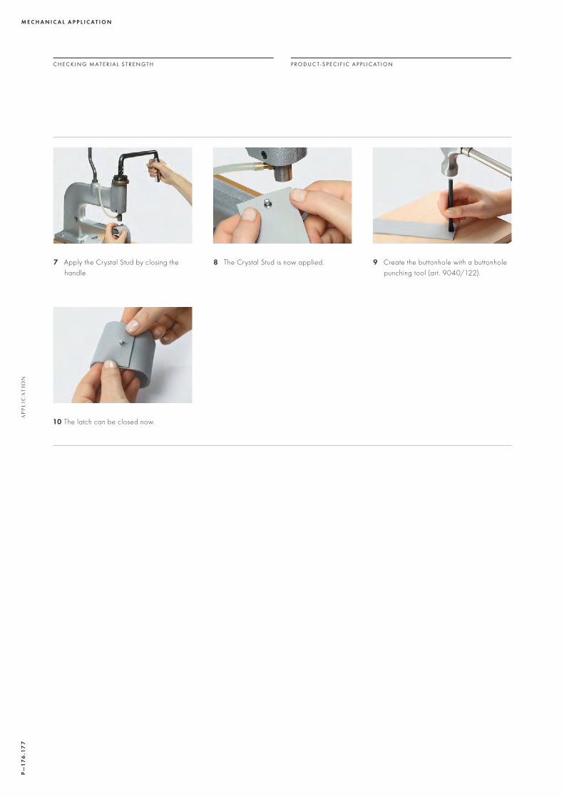
10 The latch can be closed now.
7 Apply the Crystal Stud by closing the handle.
8 The Crystal Stud is now applied. 9 Create the buttonhole with a buttonhole punching tool (art. 9040/122).
C H E C K I N G M A T E R I A L S T R E N G T H P R O D U C T - S P E C I F I C A P P L I C A T I O N

20
17/18
7
AP
PLIC
ATIO
N M
AN
UA
L
C H E C K I N G M A T E R I A L S T R E N G T H P R O D U C T - S P E C I F I C A P P L I C A T I O N
3D STUDS
This product can be applied on dif ferent carrier materials using either a fly press or a 3D Stud mold. Application tests on your carrier material of choice — especially
stretchable fabrics — are recommended. Before applying 3D Studs to any leather or fabric, please also test the metal- and especially silver compatibility with the
corresponding carrier material. Please consider the material thickness before starting the application.
ART. LENGTH OF SHANK MATERIAL THICKNESS*
3D STUDS 54 00154 00254 003
4 mm6 mm8 mm
0.7 – 1.5 mm0.7 – 1.5 mm0.7 – 1.5 mm
* This can vary according to the roughness and production of the carrier material.
Application with a fly press
First, position the upper and lower die in the press. Make sure to choose the corresponding insert for the 3D Stud to be
applied, and position it in the lower die with the cavity pointing upwards:
Upper die
3D Stud
Back Part
Lower die
Insert

P—
17
8.1
79
M E C H A N I C A L A P P L I C A T I O NA
PP
LIC
AT
ION
C H E C K I N G M A T E R I A L S T R E N G T H P R O D U C T - S P E C I F I C A P P L I C A T I O N
When the upper and lower die (with insert) are positioned in the fly press, follow the application steps:
1 Place the 3D Stud in the lower die, with the crystal side pointing downwards.
1 When a 3D Stud of another size is being applied, the corresponding plastic insert has to be changed first.
2 Attach the vacuum pump to the upper die and turn the vacuum pump on. The Back Part can now easily be positioned into the upper die with the arrow pointing downwards.
2 Take the lower die out of the fly press and press the changing pin through the small hole at the rear side of the lower die to uncase the plastic insert.
3 Position the carrier material with the right side pointing downwards. Apply the 3D Stud by carefully closing the handle of the fly press.
3 Choose the matching insert for applying a 3D Stud of another size and push it into the lower die. Make sure the cavity of the insert is located at the upper side of the tool.
Changing the plastic insert

20
17/18
7
AP
PLIC
ATIO
N M
AN
UA
L
C H E C K I N G M A T E R I A L S T R E N G T H P R O D U C T - S P E C I F I C A P P L I C A T I O N
Even positioning of 3D Studs with fly press
When the upper and lower die (with insert) are positioned in the fly press, follow the application steps:
Upper die
3D Stud
Back Part
Insert
Lower die
Linear grid
1 Set a 3D Stud (crystal pointing downwards) in the lower die with insert.
2 Lay the linear grid with the flat side pointing downwards on top of the carrier material with at least one applied 3D Stud. Make sure the applied 3D Studs sit in the grid’s cavities, leaving the big cavity in the middle empty.
3 Turn the fabric with linear grid around and put all parts into the fly press on top of the lower die. Activate the vacuum pump and fit the Back Part into the upper die. Apply the 3D Stud by closing the handle of the fly press.
To facilitate the even positioning of 3D Studs, the linear grid tool can be used. By enclosing already applied 3D Studs it makes it possible to apply further 3D Studs
very close to the existing ones. The linear grid tool has to be positioned on top of the lower die as shown in the following illustration:

P—
18
0.1
81
M E C H A N I C A L A P P L I C A T I O NA
PP
LIC
AT
ION
C H E C K I N G M A T E R I A L S T R E N G T H P R O D U C T - S P E C I F I C A P P L I C A T I O N
1 Before starting production with a new motif, the vacuum suction has to be installed in the mold. Open the cover’s plates by unscrewing the screws with a drill.
4 The mold is now ready to be equipped with the PVC masks. First open the mold.
7 When all pins are set, remove the masks and use the plastic pen to press down every single pin.
2 Place the mask for the vacuum suction channels between the two cover plates.
5 Remove the middle metal plate and put the first PVC mask onto the lower part of the mold.
8 Apply the masks again and set the 3D Studs with crystals pointing downwards. With the help of the pins, they stay evenly in the cavities.
3 Screw the plates together.
6 Insert the first pins into the mask’s cavities (colored part upwards) as height compensation for the corresponding 3D Studs. Use one mask and pin color for each 3D Stud size and repeat the setting step for all masks.
9 Put the middle metal plate back into the mold.
Application with 3D Stud mold
When a bigger quantity of 3D Studs that are one size or dif ferent sizes are applied at once, the use of a mold with cutting press is recommended. Please acquire the mold and suitable tools directly from the supplier
Gruppo Meccaniche Luciani (www.gruppomeccanicheluciani.com). Detailed information can be requested from the supplier.
When applying more than 100 3D Studs, the 3D Stud mold application is up to four times faster compared to the application with fly press.

20
17/18
7
AP
PLIC
ATIO
N M
AN
UA
L
C H E C K I N G M A T E R I A L S T R E N G T H P R O D U C T - S P E C I F I C A P P L I C A T I O N
10 Place the first mask for the Back Parts on the middle plate.
11 Depending on the motif, put a frame mask for the Back Parts onto the first mask.
12 Place the black frame on the masks. The frame makes sure no Back Parts get lost.
13 Empty the Back Parts into the black frame. Use the sponge to wipe them into the mask’s cavities (arrows pointing downwards).
16 Remove the middle metal plate and lay the fabric in the mold.
14 Remove the residual Back Parts, the black frame, and the masks. Make sure the middle metal plate stays in the mold.
17 Close the cover and place the mold into the hydraulic press.
15 Switch on the vacuum system, close the cover and then open it again. The Back Parts are now inside the cover.
18 Press with a cutting press and apply the 3D Studs all at once. Keep the vacuum system on until the end of the application.

P—
18
2.1
83
M E C H A N I C A L A P P L I C A T I O N U
SE
FU
L I
NF
OR
MA
TIO
N &
QU
ICK
AS
SIS
TA
NC
E
USEFUL INFORMATION
In general, when carrying out mechanical applications it is important to ensure the proper alignment of products in the dies, so as to avoid any problems.
Please note that during application, the product is entirely surrounded by the upper die. To prevent neighboring products from being damaged, check the minimum space required by the die when calculating the gap between each item.
DIE MAINTENANCE
Please check the dies used before and during production, and change them when they become worn.
For machines with vacuum connections, blockages in the upper die can be released using a needle.
OPTIMUM PRODUCT/DIE ALIGNMENT
MINIMUM GAPS

20
17/18
7
AP
PLIC
ATIO
N M
AN
UA
L QUICK ASSISTANCE
The following table outlines typical mechanical application problems, along with possible causes and recommendations on avoiding them.
PROBLEM CAUSE
The product is not ideally affixed onto the carrier material.The fabric ripples or crinkles.The dies cannot be inserted in the fly press.It is not possible to unscrew the dies.The crystals break.The crystals do not hold in the upper die.
1, 2, 3, 4, 52, 3, 4, 53, 6, 7, 86, 8, 9
2, 3, 4, 5, 1012, 13
CAUSE RECOMMENDATION
1 The pressure may be too low. Apply the product again using increased pressure; adjust the stop.
2 The carrier material is too thick or consists of too many layers.
With Rivets, select the smaller Back Part. With Rivets and Jeans Buttons a hole can be pre-punched.
3 The dies/spare parts for the upper die are defective or have been wrongly inserted.
Check the dies and if necessary, replace or repair them.
4 The product has been applied using the wrong dies. Check to make sure that the right dies are being used for the product.
5 The dies have not been inserted correctly. Make sure that the products are placed exactly in the right position on the dies. By turning the fly press handle slowly, it is possible to see if the upper and lower parts of the tool meet exactly.
6 The fly press and dies do not fit together. Make sure that the fly press and the upper die have the same thread size (M6 or M8).
7 The upper die cannot be fit ted. Check the fastening screw on the upper die; it may have been screwed too tightly.
8 The die/spare part may be damaged. Check the dies; if they are faulty use a new die or spare part.
9 The screw on the upper die has broken off. Carefully try to loosen the screw using pliers. Oil from time to time; it may be necessary to center-drill the die.
10 The pressure may be too high. Apply the product again using slightly less pressure; adjust the stop.
11 The die damages the crystal. Check the dies and if necessary replace the upper die or the spare parts.
12 The vacuum hose is blocked or damaged. Check and if necessary change the vacuum hose.
13 The vacuum hole in the upper die is blocked. Clean the vacuum hole and if necessary change the spare part.