appendix n rock weir design - caltrans n... · caltrans fish passage design for road crossings....
TRANSCRIPT

Caltrans Fish Passage Design for Road Crossings
APPENDIX N
ROCK WEIR DESIGN
Appendix N – Rock Weir Design August 2009

Caltrans Fish Passage Design for Road Crossings
N. Rock Weir Design N.1 Rock Weir Sizing The rock within a rock weir must resist active forces of drag, lift, and buoyancy while subjected to flowing water in a creek. The cap layer rocks, as well as the rocks beneath in a weir, will resist the collective active forces, and must be sized accordingly. The methods for sizing rocks comprising a rock weir are Field Inspection, Rock Slope Protection (RSP) Revetment Design, and Boulder Cluster Design.
After calculating rock size using the three methods mentioned above, engineering judgment shall be incorporated in deciding which result should be used for design and construction. The most conservative or largest rock size is not necessarily the best choice, especially if a great disparity exists between the sizes calculated using the other methods.
N.1.1 Field Inspection Method In addition to the project limits within the creek, upstream and downstream reaches should be investigated for large, stable rocks (boulders) in the stream that appear to be immobile during overtopping flows. Some stability indicators to look for in the field are salt and silt stains on a boulder, moss and lichen growth on a boulder, and bar or terrace development around a boulder or group of boulders. These bars typically contain vegetation, as well as coarse gravels and cobbles.
Once stable rocks are located in the field, their rough diameters need to be measured in the direction of at least two of the three principle axes (long, short, and middle). The measurements of each boulder should be averaged to find their approximate or rough diameter. After the rough diameters are determined, use Table N-1 to find the RSP Class corresponding to the rough D50 measured in the field. The information in Table N-1 is consistent with the California Bank and Shore Rock Slope Protection Design Report (CA RSP Report):
RSP Class Rough D50 (ft)
Cobble 0.66
Backing No. 1 0.95
Light 1.32
¼ Ton 1.79
½ Ton 2.26
1 Ton 2.85
2 Ton 3.59
4 Ton 4.50
8 Ton 5.70 Table N-1. RSP Class Rough Diameter
Appendix N – Rock Weir Design Page N-1 August 2009

Caltrans Fish Passage Design for Road Crossings
N.1.2 RSP Revetment Design Method When using this method, a rock weir is analyzed as a revetment following the procedures outlined in the CA RSP Report. The minimum weight of rock that will resist forces from flowing water and remain stable is calculated based on a factored velocity, rock angle of repose, and rock specific gravity.
Because the CA RSP Report equation is being applied to the sizing of a rock weir rather than an RSP revetment, certain modifications can be made. For instance, the angle of repose of the stacked/placed rock can be simplified for rock weir analysis. When stacking or placing rock to build a weir, the steepest repose angle, recommended by the CA RSP Report, will be used to reduce rock quantity, as well as improve constructability. Basically, the flatter the rock weir side slope, the wider its base width will be (See Figure N-2), and the greater potential that individual weirs within a series will intersect or conflict with each other. It would be difficult to construct the weirs to the proper dimensions and tolerances if the rocks are all merged together. This would compromise the function of the weir, in addition to complicating the construction process. So, it is advantageous to have the steepest slope feasible for rock placement to avoid these problems.
In contrast, the rock for a revetment is controlled by the natural slope of the banks and will change at each project site, whereas the rock within a weir can placed at the same angle of repose in all cases with only minor influence from each site condition. Given 1.5:1 as the recommended slope for rock weir placement for all cases, the angle of repose will be 36.3 degrees. Therefore, a modified version of the CA RSP Report equation can be expressed as follows:
( )36
1SG0.207SG0.00002VW−
=
Where:
W = minimum rock mass (pounds)
*V = 1.33 Vmax (ft/s)
SG = rock specific gravity
*In RSP revetment design, the velocity term is factored to consider parallel or impinging flow conditions. For parallel flow, the average stream velocity is multiplied by a 0.67 factor, while a 1.33 factor is applied to average stream velocity for impinging flow conditions.
For in-stream weirs, flow will be impinging on the weir in all cases and a 1.33 factor is applied to increase average stream velocity as applied in the CA RSP Report. Basically, the velocity vector from the stream flow will act directly on a weir in a perpendicular direction, and it will be also be subjected to secondary currents providing higher than average velocities. The average stream velocity should correspond with a 50-year flow at a minimum for rock weir sizing.
The calculated weight (W) will correspond to an RSP material class, which is summarized in Table N-2. For example, W= 1000 pounds corresponds to a ½ Ton RSP class, W= 2000 pounds corresponds to a 1-Ton weight class, etc. When sizing rock weirs, ½ -Ton RSP is the lightest rock to be used to ensure conservatism due to adapting design methods that were not developed specifically for rock weir analysis.
Appendix N – Rock Weir Design Page N-2 August 2009

Caltrans Fish Passage Design for Road Crossings
Caltrans RSP Class Weight (lbs)
Backing No. 1 75
Light 200
¼ Ton 500
½ Ton 1000
1 Ton 2000
2 Ton 4000
4 Ton 8000 Table N-2. Caltrans RSP Class Weights
N.1.3 Boulder Cluster Design Method This simplistic approach uses a table containing minimum boulder diameters and their associated critical shear stress (τc) and critical velocity (vc) assuming a rock/boulder angle of repose equal to 42 degrees (approximately 1.8:1) and rock specific gravity equal to 2.65. The τc and vc values were determined considering drag, lift, and buoyancy forces acting on the rocks/boulders. For the minimum diameter given in the following table, the rock/boulder will be stable during turbulent flow with it fully immersed. In other words, incipient motion will occur for a given rock/boulder diameter when stream velocities are higher than the critical velocity shown in Table N-3.
Generic Rock Class Min. Dia. (in)
τc (lb/sf)
vc (ft/s)
Very Large Boulder >80 37.4 25
Large Boulder >40 18.7 19
Medium Boulder >20 9.3 14
Small Boulder >10 4.7 10
Large Cobble >5 2.3 7
Small Cobble >2.5 1.1 5 Table N-3. Boulder Cluster Design Method- Minimum Rock Diameter If an average stream velocity equals 16 ft/s, a minimum rock diameter of 28 inches can be interpolated from Table N-3. From Table N-1, a 28-inch or 2.33-foot rough diameter boulder would be classified as a ½ Ton RSP class, having weight equal to 1000 pounds.
N.2 Rock Weir Embedment The depth or embedment of the rock weir is dependent upon the estimated scour potential for the site. An exact method for determining scour depth at a rock weir does not exist, but it can be estimated by one of two methods: Field Inspection/Topographic Survey and Toe-Scour Estimate Equation.
Appendix N – Rock Weir Design Page N-3 August 2009

Caltrans Fish Passage Design for Road Crossings
N.2.1 Field Inspection/Topographic Survey Method Because scour depths typically are not observed during the peak of a significant storm when flow and sediment movement would be at their highest, a safety factor of 1.2 is applied to observed scour depths. As flow decreases on the descending limb of a hydrograph, suspended sediment begins to deposit. This means that scour holes found in the field during clear weather conditions are smaller than during peaks of storm events.
Design Scour Depth = ( )FODD1.2
Where:
DFOD = Field Observed Depth of Scour
N.2.2 Toe-Scour Estimate Method For this method, scour depth will be calculated considering the rock weir as a stabilized bendway. Similar to a bendway section of channel, the vortex-shaped rock weir will be subjected to secondary currents, which cause higher velocities and shear stresses. These conditions will trigger greater scour around a rock weir, as well as changes in sediment transport and supply.
The toe-scour equation is empirical and was developed by synthesizing laboratory and field data. The scour depth calculation is dependent upon mean channel depth and water surface width upstream of a bend or weir, in addition to centerline bend radius and maximum water depth in bend.
Within the scour depth calculation, two ratios are incorporated. The first ratio is the centerline bend radius divided by the water surface width upstream of a bend or weir (Rc/W), while the second ration is this same water surface width divided by the mean channel depth upstream of a bend or weir. (W/Dmnc). Since the equation is empirical, limits apply to its use, more specifically to the Rc/W and W/Dmnc ratios. Based on the range of field and laboratory data sets, Rc/W is limited from 1.5 to 10 and W/Dmnc limited from 20 to 125. In other words, when W/Dmnc is calculated to be less than 20, a value of 20 must be used. Conversely, a value of 125 must be used when W/Dmnc is calculated to be above 125.
As for the Rc/W ratio, it is of course dependent upon the centerline bend radius. Because the toe-scour equation is being adapted to apply to rock weir design in straight and bending channel sections, 1.5 will be used as the default value. By using 1.5 for all cases, calculated potential scour depths will be conservative.
Finally, the equations used in estimating scour depth in this method are:
Scour Depth = mncmxb DD −
Where:
Dmxb = maximum water depth at weir (feet)
Dmnc = mean channel depth upstream of weir (feet)
Dmxb = ⎟⎟⎠
⎞⎜⎜⎝
⎛+
mncmnc D
WD 0084.072.114.1
Appendix N – Rock Weir Design Page N-4 August 2009

Caltrans Fish Passage Design for Road Crossings
Once the scour depth is calculated, this depth will be used to specify the embedment depth of the rock weir with reference to the channel bed finished grade surface. The height of rock weir above the channel bed will be determined during the hydraulics analysis.
The total height of the rock weir, equal to the height above channel bed plus the embedment depth, must be equal to or greater than the recommended RSP class thickness recommended by the CA RSP Report displayed in Table N-4.
Caltrans RSP Class Minimum Thickness (ft)
½ Ton 3.40
1 Ton 4.30
2 Ton 5.40
4 Ton 6.80
8 Ton 8.50 Table N-4. Minimum Caltrans RSP Class Thickness After the height of the weir is determined through hydraulics analysis, which is measured above the channel bed, the total rock weir thickness must be equal to or greater than the required minimum found in Table N-4. If the embedment depth plus the rock weir height is less, the minimum RSP Class layer thickness would control.
Below the rock weir, a 1.8-foot (or 2-foot) layer of Backing No. 1 RSP underlain by RSP Fabric is needed to provide filtration beneath all rock weirs. This filter layer will prevent soil movement and loss of fines from piping, and ultimately improve rock weir stability.
See Figure N-2 for embedment depth, rock weir height, and filter layer illustrations.
N.3 Rock Weir Geometry The components of rock weir geometry include crest width, side slope ratio, and plan-view radius. As mentioned previously, the side slope ratio will be 1:1.5 for all rock weirs, but the crest width and plan-view radius must be calculated. The crest width is simply expressed below, where D50 is associated with the rock weir RSP class.
Crest Width = 2 (Rock Weir D50)
The other rock weir geometry element to consider is the arc, plan-view shape. See Figure N-1. The mid-chord offset of the arc is equal to 3 times D50 of the rock weir RSP class. The chord length will equal the distance between the left and right toes of slope. After determining the mid-chord offset and chord length, the radius of the arc can be determined with the equation below:
28
2 mm
LR +=
Where:
R = rock weir radius (feet)
Appendix N – Rock Weir Design Page N-5 August 2009

Caltrans Fish Passage Design for Road Crossings
L = chord length (feet)
m = mid-chord offset= 3 D50 (feet)
Figure N-1. Rock Weir Plan
Figure N-2. Rock Weir (Type 1) Profile
Appendix N – Rock Weir Design Page N-6 August 2009

Caltrans Fish Passage Design for Road Crossings
Figure N-3. Step-Pool Profile
N.4 Step-Pool Composition The portion of the creek between rock weirs is the pool or step-pool, which has a total thickness defined in Figure N-3 as Tsp. The total thickness is measured from the creek bed finished grade to the top of the filter layer. Tsp dimensions will vary for each project depending on rock weir embedment depth and vertical step height within the pools.
As also seen in Figure N-3, the step-pool is composed of two layers of equal thickness. The top layer is either native bed material or clean sand and gravel, and these materials do not require compaction during placement. The function of the top layer is to support habitat and to allow the development of various micro-pools that will promote resting areas for fish as they move through the rock weir/step-pool system. The top layer in the step-pool can move and scour without threatening the stability of the weirs.
During construction, the top 1-feet to 3-feet of the excavated creek bed can be stockpiled on site and later placed or returned to the creek as the step-pool top layer according to specified dimensions. If the excavated material is deemed unsuitable, clean sand and gravel can be imported and placed. The following is a recommended gradation for clean sand and gravel:
Sieve Size Percentage Passing
1” 100
¾” 60-90
No. 4 25-60
No. 30 0-20 Table N-5. Clean Sand and Gravel Gradation For bottom layer of the step-pool, a rock weir backfill is recommended that has cohesive properties and well-compacted (roughly 90%), somewhat similar to structure backfill. The purpose of this rock weir backfill is to provide stability of the weir at its base, as well as aid in scour resistance. The properties of the recommended rock weir backfill are as follows:
Appendix N – Rock Weir Design Page N-7 August 2009

Caltrans Fish Passage Design for Road Crossings
Appendix N – Rock Weir Design Page N-8 August 2009
Minimum Sand Equivalent 50
Maximum Aggregate Size 3”
Maximum Plasticity Index 20
Minimum Plasticity Index 12 Table N-6. Rock Weir Backfill Properties At the downstream end of a rock weir within the step-pool, a scour pool should be constructed. This scour pool will encourage fish to rest before jumping over the rock weir and continuing their journey. As stated previously, a 2-foot flow depth shall be provided at the downstream end of a rock weir. Even though a scour pool will form naturally over time as flow plunges over a weir, the constructed scour pool will provide immediate benefit after construction.
For recommended “Place Native Creek Bed Material”, ”Clean Sand and Gravel”, and “Rock Weir Backfill” non-standard special provisions, see Appendix O.
N.5 Bank and Toe Stabilization Because of energy losses caused by rock weirs, turbulent backwaters can be created, especially during overtopping and flanking conditions. The banks and toes are vulnerable to scour under these conditions, and they should be stabilized through rock slope protection (RSP) or a combination of RSP and vegetation where appropriate.
The Caltrans standard for bank and toe protection design is in the Highway Design Manual (HDM), Chapter 870 Channel and Share Protection - Erosion Control. According to Topic 873 Design Concepts, a suggested RSP design event is the 50-year storm, average stream velocity and water surface level are calculated to determine rock size and design high water on the bank (design high water + freebroad = design height). As also stated in Topic 873, the design height estimation should, in addition, take into account other factors, such as historic high water marks, size and nature of debris, as well as construction costs. Basically, engineering judgment must be exercised in adjusting the design RSP height up or down from the calculated 50-year average flow depth, but freeboard must be considered as well.
If the combined RSP and vegetative revetment is desired, the decision for determining the minimum RSP height and design velocity is at the discretion of the District Hydraulics Engineer. The District Landscape Architect must be consulted in determining the proper plants and grasses to be specified for each project. For all projects, the toe of bank, which is highly susceptible to scour, must be stabilized with RSP to 3 feet above the toe at a minimum. See Figure N-4 for a typical step-pool cross section showing pool composition and bank protection.

Caltrans Fish Passage Design for Road Crossings
Figure N-4. Step Pool Cross Section
Appendix N – Rock Weir Design Page N-9 August 2009

Caltrans Fish Passage Design for Road Crossings
N.6 Rock Weir and Step-Pool Layout Through an iterative hydraulics analysis, the spacing and height of the rock weirs, as well as the low-flow notch/channel dimensions are verified. These components are varied during the hydraulics modeling process until the velocity and depth requirements are satisfied as outlined in the CDFG Culvert Criteria For Fish Passage and the NOAA Fisheries Guidelines For Salmonid Passage At Stream Crossings depending on target lifestage and species. When low fish-passage flow occurs, a minimum 1-foot flow depth should be maintained within the step-pools, but a minimum 2-foot depth must be provided within the “jump” pool (constructed scour pool) at the base of each weir.
For a series of rock weirs, the minimum spacing is 25 feet. This is mainly governed by the construction process, where individual rock weirs could intersect and their physical definition could be lost if they are placed too close together. Instead of having a series of individual rock weirs, a larger pile or mass will develop without clear definition of each rock weir and the pools between them. If this occurs, the rock weirs and pools will not function properly for fish passage. This is why it is important that rock weirs are at least spaced at 25-foot intervals.
At each rock weir, a 0.5-foot to 1-foot (maximum) vertical step in the new stream profile is typically placed to minimize the longitudinal pool slope between weirs and eliminate a vertical and/or velocity barrier to fish. The rock weir will dissipate the increase of energy at a step. With a flatter pool slope, the velocity and depth criteria are more easily achieved. The use of vertical steps is especially beneficial when dealing with significant elevation changes within the project limits, which would create steep pool slopes. The overall stream gradient can be softened by having up to 1-foot grade changes at each weir location, yet provide relatively flat pool slopes or smaller grade changes between weirs. For rock weir design, the pool slope can vary between 0% and 4%, but is ultimately controlled by the velocity and depth criteria.
In order to determine the number of rock weirs, the preliminary rock weir spacing, the preliminary project length, the number of step-pools, the step-pool slope (gradient), and the number of vertical steps, the procedure below should be followed. Figure N-5 shows a vertical barrier (excessive scour pool) just below a perched culvert, which is a very common application for rock weir/step-pool system in mitigating this type of barrier or impediment.
Figure N-5 Rock Weir/Step-Pool Layout
Appendix N – Rock Weir Design Page N-10 August 2009

Caltrans Fish Passage Design for Road Crossings
Appendix N – Rock Weir Design Page N-11 August 2009
Step 1: Assume a vertical step height (d1) where 0.5 feet is the minimum and 1-foot is the maximum. Find d3, the height of the vertical barrier, by subtracting the bottom elevation of the scour pool from the upstream conform elevation (top of the excessive scour pool). Divide d3 by d1 and round down to the nearest whole number to determine the number of vertical steps required to overcome the vertical barrier, which is also the number of rock weirs and step-pools.
# of Vertical Steps= # of Rock Weirs= # of Step-Pools= d3/d1 (Round Down)
Step 2: Assume a preliminary rock weir spacing (25 feet minimum) that will also equal the step-pool longitudinal length. Calculate the total project length, in other words the longitudinal length of the rock weir/step-pool system, by multiplying the number of step-pools by the step-pool length.
NOTE: The rock weir spacing and subsequent step-pool length is preliminary until depth and velocity criteria have been met, which will be verified by the hydraulic modeling.
Preliminary Rock Weir Spacing= Preliminary Step-Pool Length
Total Project Length= (# of Step-Pools) (Step-Pool Length)
Step 3: Find d2, the elevation difference in the total project length, by subtracting the downstream and upstream conform point elevations. The distance between these conform points is, of course, the total project length from Step 2. The upstream conform point is normally around the top of the scour pool.
Step 4: Determine the step-pool slope based on d1, d2, the number of vertical steps, the number of step-pools, and the step-pool length.
Step Pool Slope ( )ftft( )[ ]
( )( )lengthpoolsteppoolsstepofstepsverticalofdd
##12 −=
After the general configuration of the rock weirs and step-pools has been found following the steps above, a preliminary rock weir height (6 inches minimum) can be determined. In the hydraulics analysis, special attention must be made to maximum drops stated in the State and Federal criteria. For all adult species, the maximum drop in water surface is 1 foot, while juvenile salmonids can only tolerate 6 inches. At the downstream base of each rock weir, a 2-foot jump pool should be provided for all species and lifestage. As can be seen in Figure N-2, the rock weir height is measured from the channel finished grade to the top of the weir crest.
By using Figure N-6 and the associated equations, a preliminary (first trial) rock weir height can be found. In this Figure, a pool between two rock weirs is shown in a creek. A line representing level water surface has been drawn from the top of the upstream side of the downstream weir to the downstream side of the upstream weir. By assuming a rock weir height (h1) and using the preliminary step-pool length and slope determined above, h3 can be calculated. Once h3 is known, h4 can be determined, where (h3+h4) equals the total jump pool depth. The h4 dimension is the height or depth of the constructed scour pool and must be at least 0.5 feet for constructability purposes. From hydraulic modeling in HEC-RAS, appropriate rock weir height and spacing will be verified if h1 and h2 are of minimum depth according to lifestage/species in the CDFG and NMFS criteria, and also that (h3+h4) is around 2 feet or greater.

Caltrans Fish Passage Design for Road Crossings
Figure N-6. Preliminary Rock Weir Height Determination
h3 = h1- [(Step-Pool Length) (Step-Pool Slope in ft/ft)]
h4 = (2 feet)-h3
h3 + h4 ≥ 2 ft, where h4 ≥ 0.5 ft (minimum)
Once the weir height (preliminary or final) has been determined, the low-flow notch and low-flow channel can be sized using the following minimum dimensions: 6-inch depth, 2-foot base width, and 4-foot top width. Basically, the low-flow notch and channel dimensions will be consistent. As the name suggests, the function of the low-flow notch and channel is to provide minimum flow depths during low fish-passage flow. The top of a rock weir and the channel bed must have a 4% to 5% cross slope toward the low-flow notch/channel so that water will be concentrated and minimum depth is more easily attained. See Figure N-8 for cross sections of the low-flow notch and channel.
During construction, a rock weir is normally built in full without the notch in order to have proper placement and locking of rocks. After it is built, rock is removed to form the notch. Of course given the variable physical sizes of the individual rocks, the dimensions specified on the plans for a notch are somewhat approximate. Because of this situation, the D50 of the rock weir should also be considered in determining the dimensions of the low-flow notch. The cross-sectional dimensions of the notch cannot be less than D50.
Another factor to consider in the design of the low-flow notch and channel is meandering and sinuosity of the notch and channel in plan view. By having this, channel length is increased and longitudinal slope is decreased, which further contributes to having adequate fish-passage depth and velocity especially in a steep slope environment. While a standard for the sinusoidal pattern does not exist, the engineer can use judgment in approximating a meandering low-flow channel around the creek centerline as shown in Figure N-7.
Appendix N – Rock Weir Design Page N-12 August 2009

Caltrans Fish Passage Design for Road Crossings
Appendix N – Rock Weir Design Page N-13 August 2009
Figure N-7. Rock Weir and Low-Flow Notch/Channel Plan
Figure N-8. Low-Flow Notch/Channel Cross Section
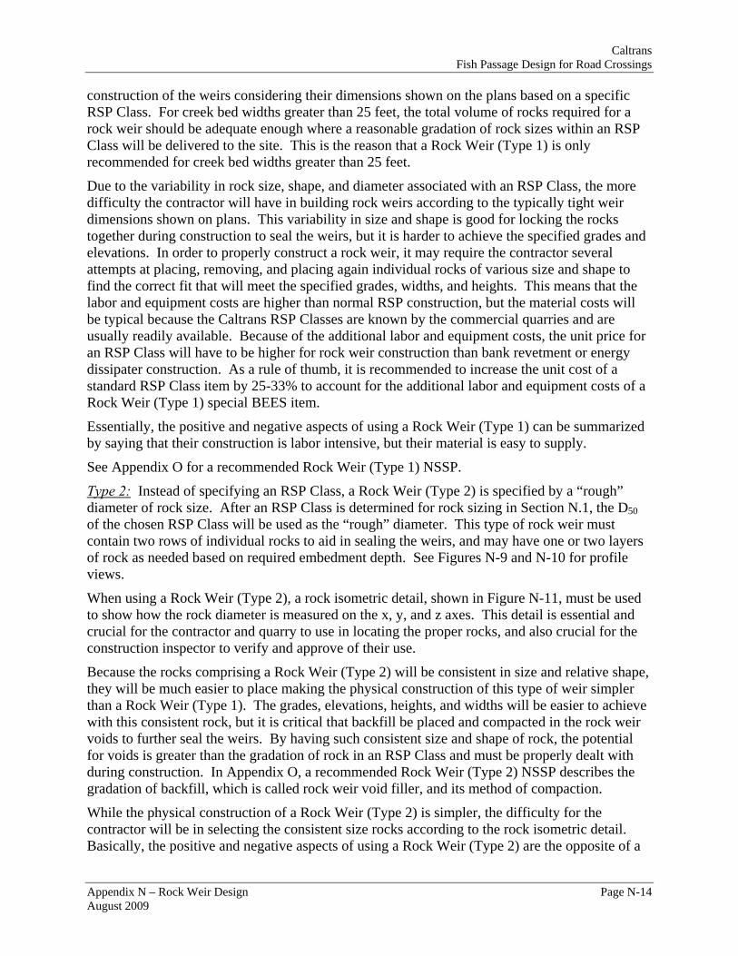
N.7 Rock Weir Types Type 1: This type of rock weir, shown in Figure N-2, is specified by RSP Class consistent with Section N.1. Within an RSP Class, the size of the actual rock can vary according to the Standard Specifications (Section 72) mass gradation. For instance, a 1-T (Ton) RSP Class could consist of 2 Ton rock size (95-100%), 1 Ton rock size (50-100%), and ½ Ton rock size (0-5%). One of the reasons for this variability in rock size is to promote a more well-graded mix that will have less voids and more stability when placed in the field.
If a creek bed width is small (less than 25 feet), the number of rocks comprising a rock weir will also be small. With fewer rocks and smaller volumes delivered to a construction site from a quarry, the potential is greater for receiving rocks that may be too large or too small for proper
Caltrans Fish Passage Design for Road Crossings
Appendix N – Rock Weir Design Page N-14 August 2009
construction of the weirs considering their dimensions shown on the plans based on a specific RSP Class. For creek bed widths greater than 25 feet, the total volume of rocks required for a rock weir should be adequate enough where a reasonable gradation of rock sizes within an RSPClass will be delivered to the site. This is the reason that a Rock Weir (Type 1) is only recommended for creek bed widths greater than 25 feet.
Due to the variability in rock size, shape, and diameter as
sociated with an RSP Class, the more
and
to
for
of a
ects of using a Rock Weir (Type 1) can be summarized
difficulty the contractor will have in building rock weirs according to the typically tight weir dimensions shown on plans. This variability in size and shape is good for locking the rocks together during construction to seal the weirs, but it is harder to achieve the specified grades elevations. In order to properly construct a rock weir, it may require the contractor several attempts at placing, removing, and placing again individual rocks of various size and shape find the correct fit that will meet the specified grades, widths, and heights. This means that thelabor and equipment costs are higher than normal RSP construction, but the material costs will be typical because the Caltrans RSP Classes are known by the commercial quarries and are usually readily available. Because of the additional labor and equipment costs, the unit pricean RSP Class will have to be higher for rock weir construction than bank revetment or energy dissipater construction. As a rule of thumb, it is recommended to increase the unit cost of a standard RSP Class item by 25-33% to account for the additional labor and equipment costs Rock Weir (Type 1) special BEES item.
Essentially, the positive and negative aspby saying that their construction is labor intensive, but their material is easy to supply.
See Appendix O for a recommended Rock Weir (Type 1) NSSP.
Type 2: Instead of specifying an RSP Class, a Rock Weir (Type 2) is specified by a “rough”
ers
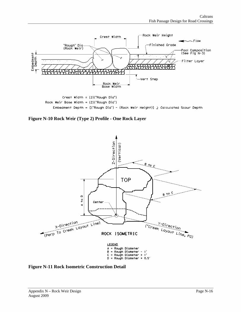
sing a Rock Weir (Type 2), a rock isometric detail, shown in Figure N-11, must be used
e consistent in size and relative shape,
e
ail.
diameter of rock size. After an RSP Class is determined for rock sizing in Section N.1, the D50of the chosen RSP Class will be used as the “rough” diameter. This type of rock weir must contain two rows of individual rocks to aid in sealing the weirs, and may have one or two layof rock as needed based on required embedment depth. See Figures N-9 and N-10 for profile views.
When uto show how the rock diameter is measured on the x, y, and z axes. This detail is essential and crucial for the contractor and quarry to use in locating the proper rocks, and also crucial for the construction inspector to verify and approve of their use.
Because the rocks comprising a Rock Weir (Type 2) will bthey will be much easier to place making the physical construction of this type of weir simpler than a Rock Weir (Type 1). The grades, elevations, heights, and widths will be easier to achievwith this consistent rock, but it is critical that backfill be placed and compacted in the rock weir voids to further seal the weirs. By having such consistent size and shape of rock, the potential for voids is greater than the gradation of rock in an RSP Class and must be properly dealt with during construction. In Appendix O, a recommended Rock Weir (Type 2) NSSP describes the gradation of backfill, which is called rock weir void filler, and its method of compaction.
While the physical construction of a Rock Weir (Type 2) is simpler, the difficulty for the contractor will be in selecting the consistent size rocks according to the rock isometric detBasically, the positive and negative aspects of using a Rock Weir (Type 2) are the opposite of a

Caltrans Fish Passage Design for Road Crossings
Appendix N – Rock Weir Design Page N-15 August 2009
Rock Weir (Type 1). For a Rock Weir (Type 2), the labor and equipment time will be normal fotypical RSP construction, if not less, but the cost in selecting and supplying the material will be much greater. In determining a unit cost for a Rock Weir (Type 2) special BEES item, it is recommended to perform a force account analysis similar to extra work construction contracchange orders for a specific project by estimating labor and equipment hours for weir construction, material costs with the additional labor in choosing the rock, delivery (truthe rock from quarry to site, and applying the proper markups and surcharges.
Given this difficulty in selecting and finding the unique rock for a Rock Weir (T
r
t
cking) of
ype 2), its ough
availability may be questionable for large volumes. A contractor may not be able to find enrock to construct the weirs for wide bottom creeks requiring large volumes. This is the main reason that this type of rock weir is recommended for smaller creek bed widths of 25 feet or less, where the volume of rock will be less and easier to provide this unique rock. The use of a Rock Weir (Type 2) for smaller stream widths will also eliminate the inconsistent rock gradationproblem, associated with an RSP Class, discussed above for a Rock Weir (Type 1).
Figure N-9 Rock Weir (Type 2) Profile - Two Rock Layers
Caltrans Fish Passage Design for Road Crossings
Figure N-10 Rock Weir (Type 2) Profile - One Rock Layer
Figure N-11 Rock Isometric Construction Detail
Appendix N – Rock Weir Design Page N-16 August 2009

Caltrans Fish Passage Design for Road Crossings
N.8 Rock Weir Hydraulic Modeling For modeling low and high fish passage flows, as well as flood flows, HEC-RAS is the software of choice given its ability to analyze in-line structures. Considering the typical crest width (breadth of crest), a rock weir is classified as broad-crested and will be analyzed in this manner by HEC-RAS. In cross section, HEC-RAS has the capability of considering a weir’s theoretical shape (in-line structure), including the low-flow notch, in its analysis by entering/defining section coordinates shown in Figure N-12, but is limited in considering a weir’s plan view orientation. As discussed in Section N.3, a weir should have an arc shape in plan view, but HEC-RAS will only recognize it with a perpendicular orientation associated with one specific River Station. Therefore, an arc-shaped rock weir must be entered as straight and perpendicular to the stream cross section at an identified River Station for hydraulic modeling purposes.
In order to develop an accurate water surface profile, it is recommended that at least three cross sections be created between rock weirs: one cross section immediately downstream of a weir, one cross section at the mid-point of the pool between weirs, and one cross section just upstream of a weir. The most critical cross section, which will have the lowest depth, is the one immediately downstream of a weir within the plunge/jump pool. Depth at this cross section especially, as well as the other cross sections, should meet minimum design criteria.
Appendix N – Rock Weir Design Page N-17 August 2009

Caltrans Fish Passage Design for Road Crossings
Figure N-12 Rock Weir Cross Section (HEC-RAS) In order to determine a broad-crested weir coefficient to be used in HEC-RAS modeling, the procedure below should be followed using Table N-6. For each flow, it is recommended to determine a new weir coefficient because of its dependency on head above a weir.
Step A: Estimate the highest weir coefficient using the highest head for the previously calculated crest width (breadth of crest of weir) from Table N-6 Broad Crested Weir Coefficient.
Step B: Run the proposed HEC-RAS model and find the average head (weir average depth) over a baffle for the Low Fish Passage Flow from HEC-RAS results.
Step C: Given the average head (weir average depth) from the HEC-RAS results and the crest width (breadth of crest of weir), find a second weir coefficient from Table N-6 Broad Crested Weir Coefficient.
Step D: Run the proposed HEC-RAS model with the second weir coefficient from Step C and find the average head (weir average depth) over a baffle for the Low Fish Passage Flow from HEC-RAS results.
Step E: Given the average head (weir average depth) from the HEC-RAS results and the crest width (breadth of crest of weir), find a third weir coefficient from Table N-6 Broad Crested Weir Coefficient.
Step F: Compare weir coefficient from Step C and Step E. If weir coefficients are close in value, then use Step E weir coefficient for remaining HEC-RAS modeling. If weir coefficients are not close in value, repeat Steps C-F until an appropriate weir coefficient is found.
Appendix N – Rock Weir Design Page N-18 August 2009

Caltrans Fish Passage Design for Road Crossings
Breadth of Crest of Weir (ft) Head
(ft) 0.50 0.75 1.00 1.50 2.00 2.50 3.00 4.00 5.00 10.00 15.00
0.2 2.80 2.75 2.69 2.62 2.54 2.48 2.44 2.38 2.34 2.49 2.68 0.4 2.92 2.80 2.72 2.64 2.61 2.60 2.58 2.54 2.50 2.56 2.70 0.6 3.08 2.89 2.75 2.64 2.61 2.60 2.68 2.69 2.70 2.70 2.70 0.8 3.30 3.04 2.85 2.68 5.60 2.60 2.678 2.68 2.68 2.69 2.64 1.0 3.32 3.14 2.98 2.75 2.66 2.64 2.65 2.67 2.68 2.68 2.63 1.2 3.32 3.20 3.08 2.86 2.70 2.65 2.64 2.67 2.66 2.69 2.64 1.4 3.32 3.26 3.20 2.92 2.77 2.68 2.64 2.65 2.65 2.67 2.64 1.6 3.32 3.29 3.28 3.07 2.89 2.75 0.68 2.66 2.65 2.64 2.63 1.8 3.32 3.32 3.31 3.07 2.88 2.74 2.68 2.66 2.65 2.64 2.63 2.0 3.32 3.31 3.30 3.03 2.85 2.76 2.72 2.68 2.65 2.64 2.63 2.5 3.32 3.32 3.31 3.28 3.07 2.89 2.81 2.72 2.67 2.64 2.63 3.0 3.32 3.32 3.32 3.32 3.20 3.05 2.92 2.73 2.66 2.64 2.63 3.5 3.32 3.32 3.32 3.32 3.32 3.19 2.97 2.76 2.68 2.64 2.63 4.0 3.32 3.32 3.32 3.32 3.32 3.32 3.07 2.79 2.70 2.64 2.63 4.5 3.32 3.32 3.32 3.32 3.32 3.32 3.32 2.88 2.74 2.64 2.63 5.0 3.32 3.32 3.32 3.32 3.32 3.32 3.32 3.07 2.79 2.64 2.63 5.5 3.32 3.32 3.32 3.32 3.32 3.32 3.32 3.32 2.88 2.64 2.63
Table N-6 Broad Crested Weir Coefficient
N.9 Rock Weir Design Steps Step 1: Prepare an Existing Conditions HEC-RAS hydraulic model and find the average
velocity for the 50-Yr Event, check existing bridge capacity for 50-Yr and 100-Yr or existing culvert capacity for 100-Yr HDM criteria.
Step 2: Calculate rock weir size.
Step 3: Find potential scour depth for rock weir embedment.
Step 4: Determine step pool composition and thickness.
Step 5: Determine crest width.
Step 6: Calculate plan view radius of vortex shape.
Step 7: Size RSP for bank and toe stabilization.
Step 8: Estimate number of steps (1 ft max per step), rock weirs, step pools, as well as linear spacing of rock weirs.
Step 9: Develop a preliminary reach profile including longitudinal slope of step pools and vertical step height.
Step 10: Estimate a trial rock weir height and “constructed” jump pool depth.
Step 11: Estimate trial geometry for low flow channel and notch (depth, bottom width, side slopes) Use minimum suggested dimensions for first trial.
Appendix N – Rock Weir Design Page N-19 August 2009

Caltrans Fish Passage Design for Road Crossings
Appendix N – Rock Weir Design Page N-20 August 2009
Step 12: Prepare HEC-RAS plan of proposed conditions using Low and High Fish Passage Design flows and determine weir coefficient through iterative process (calibrate with Low Fish Passage Flow).
Step 13: Find average weir depth and average channel depth for Low Fish Passage Flow. Check HEC-RAS Proposed Conditions 1st Trial plan against criteria. Perform hand calculations to check velocity through low flow notch. Note, velocity will be checked using High Fish Passage Flow.
Step 14: Identify velocity and depth at appropriate cross-sections from HEC-RAS model and hand calculations and compare against design criteria. If velocity or depths are not met, change rock weir spacing, rock weir height, and/or low flow channel/notch geometry to ultimately meet design criteria. Re-run HEC-RAS models and perform hand calculations as needed. Once criteria have been met, summarize calculated velocities in Velocity Criteria Versus Design (High Fish Passage Flow) and depths in Depth Criteria Versus Design (Low Fish Passage Flow) tables in Form 6E.
Step 15: Add 50-Year and/or 100-Year peak discharges to Proposed Conditions 2nd Trial Plan and evaluate results.
Step 16: Based on final weir height, calculate rock weir base width.