amba design kit user guide - pudn.comread.pudn.com/downloads62/sourcecode/embed/214634/... · this...
TRANSCRIPT

AMBA Design KitUser Guide
ARM DUI 0183AConfidential

AMBA Design Kit User GuideCopyright © ARM Limited 2003. All rights reserved.
Release information
Proprietary notice
Words and logos marked with ® or ™ are registered trademarks or trademarks owned by ARM Limited, except as otherwise stated below in this proprietary notice. Other brands and names mentioned herein may be the trademarks of their respective owners.
Document confidentiality status
This document is ARM Confidential. This document must only be distributed to ARM employees or NDA signatories.
Product status
The information in this document is Final (information on a developed product).
ARM web address
http://www.arm.com
Change history
Date Issue Change
February 2002 A First release
Neither the whole nor any part of the information contained in, or the product described in, this document may be adapted or reproduced in any material form except with the prior written permission of the copyright holder.
The product described in this document is subject to continuous developments and improvements. All particulars of the product and its use contained in this document are given by ARM Limited in good faith. However, all warranties implied or expressed, including but not limited to implied warranties or merchantability, or fitness for purpose, are excluded.
This document is intended only to assist the reader in the use of the product. ARM Limited shall not be liable for any loss or damage arising from the use of any information in this document, or any error or omission in such information, or any incorrect use of the product.
ii Copyright © ARM Limited 2003. All rights reserved. ARM DUI 0183AConfidential

ContentsAMBA Design Kit User Guide
PrefaceAbout this document .................................................................................................. 1-viFurther reading..........................................................................................................1-viiiFeedback ................................................................................................................... 1-ix
Chapter 1 Introduction1.1 About ADK ....................................................................................................1-21.2 Example ADK systems..................................................................................1-31.3 Filename extensions .....................................................................................1-6
Chapter 2 Installation2.1 Unpacking .....................................................................................................2-22.2 Directory structure.........................................................................................2-32.3 Quick start .....................................................................................................2-42.4 Library files..................................................................................................2-10
Chapter 3 Software for Core-based Example Systems3.1 Overview .......................................................................................................3-23.2 Building the application .................................................................................3-33.3 Memory map .................................................................................................3-63.4 Initialization ...................................................................................................3-83.5 Integration test ............................................................................................3-163.6 Hello World demonstration..........................................................................3-23
ARM DUI 0183A Copyright © ARM Limited 2003. All rights reserved. iiiConfidential

3.7 Supporting new EASY components ........................................................... 3-24
Chapter 4 Running the Example Systems4.1 Makefiles ...................................................................................................... 4-24.2 File reader bus master.................................................................................. 4-5
Chapter 5 Creating a Custom System5.1 Adding new AMBA peripherals..................................................................... 5-25.2 Creating a testbench .................................................................................... 5-45.3 Simulating the testbench .............................................................................. 5-6
Appendix A Makefile StructureA.1 Introduction................................................................................................... A-2A.2 Environment variables and makefile macros................................................ A-4A.3 Makefiles for an example component........................................................... A-6A.4 Makefiles for a structural component.......................................................... A-12
iv Copyright © ARM Limited 2003. All rights reserved. ARM DUI 0183AConfidential

Preface
This preface introduces the ARM AMBA Design Kit (ADK) and its reference documentation. It contains the following sections:
• About this document on page vi
• Further reading on page viii
• Feedback on page ix.
ARM DUI 0183A Copyright © ARM Limited 2003. All rights reserved. vConfidential

About this document
This document is the user guide for the ADK.
Intended audience
This document has been written for System-on-Chip (SoC) designers and system architects, and provides a description of how to use the Example AMBA SYstems (EASYs) within ADK.
Using this manual
This document is organized into the following chapters:
Chapter 1 Introduction
Read this chapter for an overview of the ADK and the example systems provided.
Chapter 2 Installation
Read this chapter for information on how to install the ADK.
Chapter 3 Software for Core-based Example Systems
Read this chapter for details on setting up and running the software for the core-based examples system provided with the ADK.
Chapter 4 Running the Example Systems
Read this chapter for details on setting up and running the example systems provided with the ADK.
Chapter 5 Creating a Custom System
Read this chapter for details on how to create your own ADK system, based on the example systems.
Appendix A Makefile Structure
Read this chapter for the structure and description of the makefiles supplied with the ADK.
vi Copyright © ARM Limited 2003. All rights reserved. ARM DUI 0183AConfidential

Typographical conventions
The following typographical conventions are used in this document:
bold Highlights ARM processor signal names, and interface elements such as menu names. Also used for terms in descriptive lists, where appropriate.
italic Highlights special terminology, cross-references, and citations.
monospace Denotes text that can be entered at the keyboard, such as commands, file names and program names, and source code.
monospace Denotes a permitted abbreviation for a command or option. The underlined text can be entered instead of the full command or option name.
monospace italic Denotes arguments to commands or functions where the argument is to be replaced by a specific value.
monospace bold Denotes language keywords when used outside example code.
ARM DUI 0183A Copyright © ARM Limited 2003. All rights reserved. viiConfidential

Further reading
This section lists publications by ARM Limited, and by third parties.
ARM periodically provides updates and corrections to its documentation. See http://www.arm.com for current errata sheets and addenda.
See also the ARM Frequently Asked Questions list at: http://www.arm.com/DevSupp/Sales+Support/faq.html.
ARM publications
This document contains information that is specific to the ADK. Refer to the following documents for other relevant information:
• AMBA Specification (Rev 2.0) (ARM IHI 0011)
• ARM Architecture Reference Manual (ARM DDI 0100)
• ADK Technical Reference Manual (ARM DDI 0243)
• Reference Peripherals Specification (ARM DDI 0062).
• ARM Developer Suite Version 1.1 Developer Guide (ARM DUI 0056)
• ARM Application Note 53 (Configuring ARM Caches).
Other publications• IEEE 1149.1 JTAG standard.
viii Copyright © ARM Limited 2003. All rights reserved. ARM DUI 0183AConfidential

Feedback
ARM Limited welcomes feedback both on the ADK, and on the documentation.
Feedback on the ADK
If you have any comments or suggestions about this product, contact your supplier giving:
• the product name
• a concise explanation of your comments.
Feedback on this document
If you have any comments about this document, send an email to [email protected] giving:
• the document title
• the document number
• the page number(s) to which your comments refer
• a concise explanation of your comments.
General suggestions for additions and improvements are also welcome.
ARM DUI 0183A Copyright © ARM Limited 2003. All rights reserved. ixConfidential

x Copyright © ARM Limited 2003. All rights reserved. ARM DUI 0183AConfidential

Chapter 1Introduction
This chapter provides an introduction to the AMBA Design Kit (ADK). The chapter gives information about the overall structure and individual modules that constitute the ADK. It contains the following sections:
• About ADK on page 1-2
• Example ADK systems on page 1-3
• Filename extensions on page 1-6.
ARM DUI 0183A Copyright © ARM Limited 2003. All rights reserved. 1-1Confidential

Introduction
1.1 About ADK
The ADK comprises the building blocks required to create an example system based on the low-power, generic design methodology of the Advanced Microcontroller Bus Architecture (AMBA). Preconfigured and validated example systems enable custom devices to be developed in very short design cycles. This allows the resulting subcomponents to be easily reused in future designs.
Note
The FRBM EASY, ARM7TDMI, and Multi-Layer ARM922T systems will shortly be complemented with ARM946E and ARM1022T systems, demonstrating core-based designs and particular uses of certain powerful infrastructure components.
The ADK enables designers to create AMBA-based components and System-on-Chip (SoC) designs. The ADK toolkit provides the following capabilities:
• A fully working simulation environment to enable you to become familiar with the AMBA protocol.
• A development environment for AMBA modules.
• VHDL and Verilog language support.
After reading this User Guide, you will be able to do the following:• set up the example ADK system
• modify the system to your requirements, by following the examples provided.
Note
For more information on the ADK and its components, and the default system address map, see the ADK Technical Reference Manual.
1-2 Copyright © ARM Limited 2003. All rights reserved. ARM DUI 0183AConfidential

Introduction
1.2 Example ADK systems
This release of the ARM ADK contains three example Advanced Microcontroller Bus Architecture (AMBA) systems, together with all the scripts required to:
• run simulations based on it (using either Mentor ModelSim or Cadence LDV)
• synthesize it (using Synopsys Design-Compiler).
All ADK example systems are prefixed by the name EASY (Example AMBA SYstem). The systems included in this release are:
• FRBM-based example AMBA system (EASY_FRBM) on page 1-3
• ARM7TDMI-based example AMBA system (EASY_ARM7) on page 1-4
• ARM922T-based example AMBA system (EASY_ML) on page 1-5.
1.2.1 FRBM-based example AMBA system (EASY_FRBM)
The File Reader Bus Master (FRBM) is an Advanced High-Performance Bus (AHB) bus master that reads bus stimulus and expected responses from a text file. This system is designed to enable very rapid out-of-the box use of AMBA, including:
• observing AMBA behavior in an existing system
• adding new masters and slaves into an otherwise stable environment
• developing infrastructure for systems without using an ARM core.
The structure of EASY_FRBM is shown in Figure 1-1.
Figure 1-1 EASY_FRBM example AMBA system
File reader
bus master
Example
bus master
Arbiter
Decoder
Reset
control
IRQ
controllerRetry slave
Default
slave
Internal
memory
AHB to APB
bridge
Timers
Remap/
pause
Example
APB slave
Watchdog
GPIO
Tube
ARM DUI 0183A Copyright © ARM Limited 2003. All rights reserved. 1-3Confidential

Introduction
1.2.2 ARM7TDMI-based example AMBA system (EASY_ARM7)
This example provides a complete working example of an ARM7TDMI-based ASIC design. The design is supplied with:
• example software to run in the system
• synthesis scripts to generate a netlist version of the design
• examples of the use of a production test interface that allows the application of functional test vectors to the core.
Figure 1-2 shows the EASY_ARM7 example AMBA system.
Figure 1-2 EASY_ARM7 example AMBA system
ARM7TDMIARM
test
Decoder
Default
slave
Internal
memory
Retry
slave
IRQ
controller
Example
bus master
Arbiter
Reset control
AHB 2 APB
bridge
Timers
Remap/pause
EgAPB slave
Watchdog
GPIO
TIC SMI
Extermal
access
ExtROM TubeExtRAMTicbox
AHB-AHB
bridge
Default
slave
Decoder
1-4 Copyright © ARM Limited 2003. All rights reserved. ARM DUI 0183AConfidential
Introduction
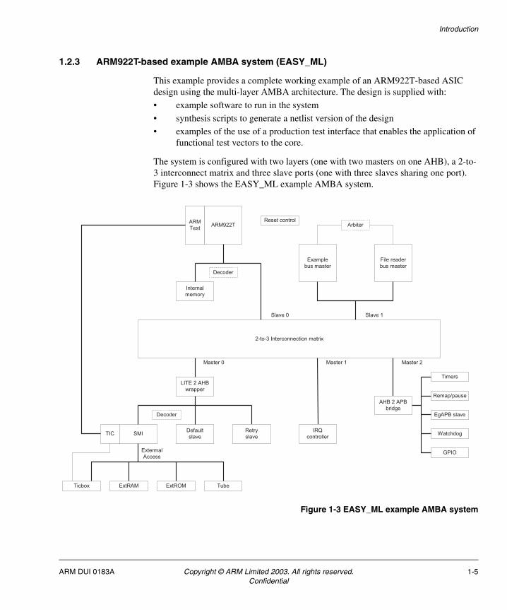
1.2.3 ARM922T-based example AMBA system (EASY_ML)
This example provides a complete working example of an ARM922T-based ASIC design using the multi-layer AMBA architecture. The design is supplied with:
• example software to run in the system
• synthesis scripts to generate a netlist version of the design
• examples of the use of a production test interface that enables the application of functional test vectors to the core.
The system is configured with two layers (one with two masters on one AHB), a 2-to-3 interconnect matrix and three slave ports (one with three slaves sharing one port). Figure 1-3 shows the EASY_ML example AMBA system.
Figure 1-3 EASY_ML example AMBA system
ARM922T
TIC
ARM
Test
Decoder
File reader
bus master
2-to-3 Interconnection matrix
SMI
Decoder
Default
slave
Internal
memory
Extermal
Access
Retry
slave
AHB 2 APB
bridge
Timers
Remap/pause
EgAPB slave
IRQ
controller
LITE 2 AHB
wrapper
Watchdog
Example
bus master
Arbiter
GPIO
Slave 0 Slave 1
Master 0 Master 1 Master 2
ExtROM TubeExtRAMTicbox
Reset control
ARM DUI 0183A Copyright © ARM Limited 2003. All rights reserved. 1-5Confidential

Introduction
1.3 Filename extensions
Table 1-1 shows the filename extensions used throughout this document.
Table 1-1 ADK filename extensions
Extension File type
.pl PERL script
.log Log file
.tar Tape archiver file (UNIX)
.gz Archiver file (UNIX)
.pdf Adobe Acrobat document
.ini ModelSim initialization configuration setting
.csh C-Shell script
.do ModelSim do file
.easy ModelSim file
.mk Makefile include file
.files NC Sim file
.txt Readme text file
.fri File reader bus master input stimulus
.frd File reader bus master stimulus data
.scr Synopsys script (constraints)
.cmd Synopsys command file
.v Verilog source
.vhd VHDL source
.c C source code file
.s Assembler source code file
.h C header file
.o Object code file
.axf Executable image file
.scf Scatter-loading description file
.mcp CodeWarriorIDE project file
1-6 Copyright © ARM Limited 2003. All rights reserved. ARM DUI 0183AConfidential

Chapter 2Installation
This chapter provides information on how to install the AMBA Design Kit (ADK). It contains the following sections:
• Unpacking on page 2-2
• Directory structure on page 2-3
• Quick start on page 2-4
• Library files on page 2-10.
ARM DUI 0183A Copyright © ARM Limited 2003. All rights reserved. 2-1Confidential

Installation
2.1 Unpacking
The ADK is supplied as a single compressed .tar file.
CautionThis file has been prepared in a UNIX environment. Attempting to unpack it in a non-UNIX environment (for example, using WinZip) can corrupt some of the files by converting them to an alternative text format.
To unpack the files:
mkdir /path_to_install
cp ARM_ADK_<release>.tar.gz /path_to_install
cd /path_to_install
gunzip ARM_ADK_<release>.tar.gz
tar xvf ARM_ADK_<release>.tar
This unpacks all files into the subdirectory ARM_ADK_<release> under the current directory.
2-2 Copyright © ARM Limited 2003. All rights reserved. ARM DUI 0183AConfidential

Installation
2.2 Directory structure
In general, each component or EASY system within ADK is stored in a separate subdirectory within the following directory:
/path_to_install/ARM_ADK_<release>/design
The name of the subdirectory matches the component name. For example, the Watchdog component is stored in the directory:
/path_to_install/ARM_ADK_<release>/design/Watchdog
There are some exceptions:
• all AHB bus components are stored in the ElementsAHB subdirectory
• all APB bus components are stored in the ElementsAPB subdirectory
• internal memory models are stored in the InternalMemory subdirectory
• external memory models are stored in the ExternalMemory subdirectory.
In addition, a testbench directory (such as TBEasy_FRBM) contains all the supplied testbenches, which provide external stimulus (such as clock creation) required for simulation. The global_ADK directory contains all common scripts, makefiles, subcomponents and tools required by the rest of ADK.
Each component directory can contain the following subdirectories:
vhdl VHDL source for the component. Present for all ADK components.
verilog Verilog source for the component. Present for all ADK components.
synopsys Component-specific synthesis scripts. Only present for synthesizable components.
integration Only present in the testbench directories. This area contains the source files for tests which are to be executed through the FRBM (except for EASY_ARM7), and also contains the subdirectories in which the tests are run.
The example software to run on core-based EASY systems is located in:
/path_to_install/ARM_ADK_<release>/ADScode
See Chapter 3 Software for Core-based Example Systems for more information.
ARM DUI 0183A Copyright © ARM Limited 2003. All rights reserved. 2-3Confidential

Installation
2.3 Quick start
The instructions in this section assume that the relevant tools (such as vsim and ncverilog) are available for use in the UNIX shell from which the make commands are run.
In addition, the ARM Developer Suite (Version 1.1 or later) running under Windows or UNIX is required to build the example software for core-based EASY systems.
The core-based EASY systems use an ARM Design Signoff Model (DSM). These DSMs are available as part of the licensed core deliverables, or as standalone models if specifically requested.
Although the instructions use the make command under Solaris 2.8, the makefiles are also designed to work with gnumake, if necessary.
The following procedures are described in this section:
• Setting up environment variables on page 2-4
• Setting up the DSM on page 2-5
• Running integration tests on HDL source on page 2-6
• Synthesizing all synthesizable components in an EASY on page 2-7
• Running integration tests on synthesized netlist with SDF back-annotation on page 2-9.
2.3.1 Setting up environment variables
To set up the environment variables:
cd /path_to_install/ARM_ADK_<release>/design
source sourceMe
The default setup for ADK is:
• Solaris 2.8 operating system
• VHDL source files
• ModelSim simulator
• Verilog target netlist
• scan insertion test methodology.
To alter these parameters, edit the sourceMe file and re-issue the source sourceMe command. The sourceMe file sets up various other cell-library related parameters.
2-4 Copyright © ARM Limited 2003. All rights reserved. ARM DUI 0183AConfidential
Installation
It also sets the following environment variables:
$ADK This points to the ADK installation directory. This is used to abbreviate the subsequent instructions.
$ADSCODE This points to $ADK/ADScode, which is the directory containing the example software for core-based EASY systems.
$ADSUNIX This indicates whether UNIX or Windows version of ADS is used to compile the EASY software. The default is UNIX.
The sourceMe file sets up which EASY testbench is to be used (the default is TBEasy_FRBM), and it then sources a second file located in the specified EASY testbench, for example:
$ADK/design/TBEasy_FRBM/sourceMe.TBEasy_FRBM
The file which is sourced in the testbench directory sets up:
• $EASY (the EASY system)
• $TEST_ENV (the test environment)
• $TEST_BENCH (the testbench)
• $TEST_NAME (the test to be run on the system)
• $TEST_NAME_ROM (the test to be loaded into memory and run on the ARM core).
Thus an EASY testbench can be set up from $ADK/design/sourceMe or directly from a testbench directory.
2.3.2 Setting up the DSM
Note
This section is only relevant if you are using an ARM core-based EASY.
To set up the Design Signoff Model (DSM) of the ARM core:
• Ensure you have the version of the DSM corresponding to your simulator and chosen HDL.
• Unzip, then extract from the tar file, the release directory of the DSM to a directory of your choice.
• Follow the instructions in the README file in the DSM release directory.
ARM DUI 0183A Copyright © ARM Limited 2003. All rights reserved. 2-5Confidential

Installation
2.3.3 Running integration tests on HDL source
Integration tests are provided for the following EASY systems:
• EASY_FRBM on page 2-6
• EASY_ARM7 on page 2-6
• EASY_ML on page 2-7.
EASY_FRBM
To run the integration tests for EASY_FRBM:
cd $ADK/design/TBEasy_FRBM/integration
make rtl
This compiles the test source file located in$ADK/design/TBEasy_FRBM/frbmtests/IntegrationTest.fri,and runs it on EASY_FRBM using the TBEasy_FRBM testbench. The run directory (for the default setup) is$ADK/design/TBEasy_FRBM/integration/vhdl/TBEasy_FRBM_rtl.
The test is self-checking, and reports error messages in the transcript file available in the run directory.
EASY_ARM7
Ensure that $ADK/design/TBEasy_ARM7/sourceMe.TBEasy_ARM7 specifies the test you require. This can be one of the following:
• Integration test running on the core
• Hello World Demo running on the core.
To run the integration tests for EASY_ARM7:
cd $ADK/design/TBEasy_ARM7
source sourceMe.TBEasy_ARM7
cd $ADK/design/TBEasy_ARM7/integration
make rtl
This invokes the makefile located in $ADSCODE/build which builds the test software for the core in the EASY_ARM7 (see Chapter 3Software for Core-based Example Systems for more information) and runs it on EASY_ARM7 using the TBEasy_ARM7 testbench.
The run directory is $ADK/design/TBEasy_ARM7/integration/vhdl/TBEasy_ARM7_rtl.
The test is self-checking, and reports error messages in the transcript file available in the run directory.
2-6 Copyright © ARM Limited 2003. All rights reserved. ARM DUI 0183AConfidential

Installation
EASY_ML
Ensure that $ADK/design/TBEasy_ML/sourceMe.TBEasy_ML specifies the test you require. This can be one of the following:
• FRBM only test
• Integration test running on the core (demonstrates multi-master operation)
• Hello World Demo running on the core.
To run the integration tests for EASY_ML:
cd $ADK/design/TBEasy_ML
source sourceMe.TBEasy_ML
cd $ADK/design/TBEasy_ML/integration
make rtl
This invokes the makefile located in $ADSCODE/build which builds the test software for the core in the EASY_ML (see Chapter 3 Software for Core-based Example Systems for more information). It also compiles a test source file located in $ADK/design/TBEasy_ML/frbmtests/ for the FRBM and runs both on EASY_ML using the TBEasy_ML testbench
Note
Only the integration test actually tests multi-master operation.
The run directory is $ADK/design/TBEasy_ML/integration/vhdl/TBEasy_ML_rtl.
The tests are self-checking, and report error messages in the transcript file available in the run directory.
2.3.4 Synthesizing all synthesizable components in an EASY
Before synthesis, the supplied cell-library files must be unpacked. See Library files on page 2-10 for more details.
To synthesize EASY_FRBM:
cd $ADK/design/EASY_FRBM/synopsys
make netlist
To synthesize EASY_ARM7:
cd $ADK/design/EASY_ARM7/synopsys
make netlist
To synthesize EASY_ML:
cd $ADK/design/EASY_ML/synopsys
make netlist
ARM DUI 0183A Copyright © ARM Limited 2003. All rights reserved. 2-7Confidential

Installation
Table 2-1 indicates which ADK components are nonsynthesizable.
All other components are synthesized using a bottom-up methodology. Each subcomponent is synthesized separately, and the resulting Synopsys database (.db) files are used when synthesizing the mainly structural top-level. This entire process can take some time (up to several hours), depending on the available computing power.
A synthesis log and a number of report files are generated for each component. The primary files (for example, for the Watchdog) are:
$ADK/design/Watchdog/synopsys/log/Watchdog_scaninsert_vhdl_verilog_run.log
This is the primary log file of the synthesis run. Although it contains a number of Warning: statements because of the nature of the Synopsys tools, any Error: statements must be closely investigated.
$ADK/design/Watchdog/synopsys/report/Watchdog_scaninsert_vhdl_verilog.min
$ADK/design/Watchdog/synopsys/report/Watchdog_scaninsert_vhdl_verilog.max
These are timing reports of the design, for MIN (best-case) and MAX (worst-case) timings. Any paths that fail to meet the applied timing constraints are indicated by the text VIOLATED and must be investigated.
Table 2-1 Nonsynthesizable EASY components
Component Description System
FileReader File Reader Bus Master, of which the only nonsynthesizable part is the file reader core itself.
EASY_FRBM EASY_ML
IntMem Behavioral internal memory model. EASY_FRBM EASY_ML EASY_ARM7
TBEasy_FRBM Testbench for EASY_FRBM. -
TBEasy_ML Testbench for EASY_ML. -
TBEasy_ARM7 Testbench for EASY_ARM7. -
TBEasy_ML_TIC TIC testbench for EASY_ML. -
TBEasy_ARM7_TIC TIC testbench for EASY_ARM7. -
TicBox External AMBA TIC testbox. Reads data from input file and outputs AMBA test interface signals.
TBEasy_ML_TIC TBEasy_ARM7_TIC
Tube Simple method of passing system messages from a test program to the simulator display.
TBEasy_FRBMTBEasy_MLTBEasy_ARM7
2-8 Copyright © ARM Limited 2003. All rights reserved. ARM DUI 0183AConfidential

Installation
2.3.5 Running integration tests on synthesized netlist with SDF back-annotation
Before running netlist simulations, the cell-library simulation models must be compiled, if you are using the modelsim simulator. See Library files on page 2-10 for more details.
To run the integration tests (<testbench> indicates TBEasy_FRBM, TBEasy_ARM7, or TBEasy_ML):
cd $ADK/design/<testbench>/integration
make net_max
make net_typ
make net_min
This runs the integration test on the synthesized netlist using MIN (best-case) timings, TYP (typical) timings and then MAX (worst-case) timings from the SDF file.
Note
As supplied, the Synopsys synthesis scripts place only MIN and MAX timings into the SDF file. Running the TYP integration test simply repeats the effects of the MAX test, but in a different run directory.
The run directories are (respectively):
$ADK/design/<testbench>/integration/verilog/<testbench>_scaninsert_vhdl_net_max
$ADK/design/<testbench>/integration/verilog/<testbench>_scaninsert_vhdl_net_typ
$ADK/design/<testbench>/integration/verilog/<testbench>_scaninsert_vhdl_net_min
The verilog subdirectory (in the integration directory) indicates the HDL type of the files being simulated. In this case, it is verilog because that is the HDL type of the netlists. The vhdl in the run directory name indicates the HDL type of the source files used during synthesis.
ARM DUI 0183A Copyright © ARM Limited 2003. All rights reserved. 2-9Confidential

Installation
2.4 Library files
This section describes how to prepare the Avant! library files. The release includes a number of files for the Avant! CB18 cell library which are required for synthesis, and post-synthesis netlist simulation. These are supplied in a separate compressed .tar file within the main archive. To unpack them ready for use:
cd /path_to_install/ARM_ADK_<release>
gunzip Avanti_CB18_2001.2_cb18os220.tar.gz
tar xvf Avanti_CB18_2001.2_cb18os220.tar
If required, these files can be placed in an entirely different location. If this is done, the file /path_to_install/ARM_ADK_<release>/design/sourceMe must be edited to change the setting of the following environment variables:• LIB_SYNOP• FILES_VERILOG• DIRS_VERILOG• DIRS_VHDL• LIB_VHDL
If Mentor ModelSim is to be used for simulation, the relevant cell library models have to be compiled before use. This is not done by the makefiles supplied with ADK, because it only has to be done once per project.
For VHDL simulation using VITAL models
cd /path_to_install/ARM_ADK_<release>/avanti/2001.2/cb18/v1.0/vital/cb18os120/zero
vlib work
vcom cb18os120_components.vhd
vcom cb18os120.vhd
For Verilog simulation
cd /path_to_install/ARM_ADK_<release>/avanti/2001.2/cb18/v1.0/verilog/cb18os120/zero
vlib work
vlog *.v
2-10 Copyright © ARM Limited 2003. All rights reserved. ARM DUI 0183AConfidential

Chapter 3Software for Core-based Example Systems
This chapter provides information on setting up and running the software for the core-based example system provided with the AMBA Design Kit (ADK). It contains the following sections:
• Overview on page 3-2
• Building the application on page 3-3
• Memory map on page 3-6
• Initialization on page 3-8
• Integration test on page 3-16
• Hello World demonstration on page 3-23
• Supporting new EASY components on page 3-24.
ARM DUI 0183A Copyright © ARM Limited 2003. All rights reserved. 3-1Confidential

Software for Core-based Example Systems
3.1 Overview
Two examples of application code are provided, which run on the ARM processor model in an EASY system:
• the first example performs integration testing of the EASY system
• the second is a simple Hello World demonstration.
The applications use the same system initialization code.
The purpose of the integration test application is to confirm that the EASY system integration has been successful. Connections between blocks are verified and EASY system peripherals are accessed. Other aspects of system operation, such as remapping, watchdog reset, and exception handling are also tested.
Note
Full functional operation of each block is not verified.
If you modify the EASY system, it is simple to modify the integration test code to match the new system.
The purpose of the Hello World application is to demonstrate the basic operation of the simulation environment and to indicate that no fundamental errors have been made during the preparation and compilation of the HDL.
The applications are written mainly in C, with some assembler files. The code is compiled into ARM native binary format, then converted into a memory image that is read in by the HDL test bench.
3-2 Copyright © ARM Limited 2003. All rights reserved. ARM DUI 0183AConfidential

Software for Core-based Example Systems
3.2 Building the application
This section describes how to build the application. It contains the following subsections:
• Directories on page 3-3
• Files on page 3-4
• Targets on page 3-4
• ROM image on page 3-4
• Unix platform on page 3-5
• Windows platform on page 3-5
• Cleaning the ADScode area on page 3-5
• Code generation options on page 3-5
• Tool versions on page 3-5.
3.2.1 Directories
The top-level directory for the EASY application code is $ADK/ADScode (referred to as $ADSCODE). It contains the subdirectories shown in Table 3-1.
Table 3-1 Subdirectories for EASY application code
Subdirectory Description
build Contains the ADS project file (EASY.mcp), the top level makefile, and scatter-loading description files.
build/EASY_Data/< target >/ Data directory. At the end of a successful build, this directory will contain the rom image (rom0, rom1, rom2, rom3), and the executable image (.axf) for the target.
build/EASY_Data/< target >/ ObjectCode Object code directory. Contains the makefile and object code for the target.
common Files that are common to both the integration test application and the Hello World demonstration, such as initialization code and memory map control.
helloworld Contains C code for the Hello World demonstration.
memory_ctrl Contains C and assembler code for memory management using an MMU/PU, caches, and write buffers.
peripherals Files defining peripheral registers.
test_app Contains C and assembler code for the integration test application.
ARM DUI 0183A Copyright © ARM Limited 2003. All rights reserved. 3-3Confidential

Software for Core-based Example Systems
3.2.2 Files
Files relating to building the software are located in the build directory, and are shown in Table 3-2.
3.2.3 Targets
The EASY software application code can be built to run on different EASY systems. Each combination of application code and EASY system, known as the target, has the following:
• a data directory
• an object code directory
• its own scatter-loading file.
The currently supported targets are shown in Table 3-3.
3.2.4 ROM image
For the EASY application code to be loaded into an HDL simulator, the compiled target image must be converted into a rom image. A rom image consists of four files (banks) of 8-bit hex data. These files are called rom0, rom1, rom2, and rom3.
The ARM fromELF utility is used to convert the executable image to hex data file format.
Table 3-2 Files in build directory
File name Description
EASY.mcp Code Warrior project file.
makefile Makefile (for Unix).
StdMakefile.mk Make include file.
<target>.scf Scatter-loading description files for the target.
Table 3-3 Supported targets
Target Description
easy_92_it Integration test application on EASY_ML
easy_92_hw Hello World demonstration on EASY_ML
easy_7_it Integration test application on EASY_ARM7
easy_7_hw Hello World demonstration on EASY_ARM7
blank Dummy target required for FRBM integration test on EASY_ML
3-4 Copyright © ARM Limited 2003. All rights reserved. ARM DUI 0183AConfidential

Software for Core-based Example Systems
3.2.5 Unix platform
The example code is built by executing the top-level makefile in the build directory. The top-level makefile calls a target-specific makefile to generate the required object code.
The makefiles require environment variables to determine the target and the location of the EASY software. These environment variables are set up as part of the ADK system initialization (see Setting up environment variables on page 2-4).
Alternatively, if the software is being built separately from the testbench, these environment variables can be set up by:setenv ADSCODE - /path_to_install/ARM_ADK_<release>/ADSCODE
setenv TEST_NAME_ROM = easy_7_hw
The makefiles are designed to work with Solaris make and gnumake. The file StdMakefile.mk is included in all the other makefiles.
3.2.6 Windows platform
An ADS CodeWarrior project file (EASY.mcp) can be used to build the software on a Windows platform. EASY.mcp supports several targets and enables either the integration test application or the Hello World demonstration to be built for a particular EASY system.
The CodeWarrior project file uses the Post Linker facility to run the ARM fromELF utility as the final step in the link process.
If the software is built on a Windows platform, the environment variable $ADSUNIX must be set to no before building the testbench (see Setting up environment variables on page 2-4).
3.2.7 Cleaning the ADScode area
The top-level makefile includes a target called clean. This target is used to remove object files (.o), the executable image file (.axf), and rom image files (rom*) for the EASY target currently specified.
3.2.8 Code generation options
When adding your own code to the EASY application software, be aware that the compiler/linker flags specified in StdMakefile.mk do not specify ARM/Thumb interworking and that the no floating-point option is specified.
If you need to support ARM/Thumb interworking or use floating-point architecture, the compiler/linker flags must be changed.
3.2.9 Tool versions
The code has been designed to be built using ADS 1.1 or later. It is not possible to build the code using any version of SDT.
ARM DUI 0183A Copyright © ARM Limited 2003. All rights reserved. 3-5Confidential

Software for Core-based Example Systems
3.3 Memory map
A diagram of the memory map is shown in Chapter 1 of the ADK Technical Reference Manual. The memory map is described in the following subsections:
• Remap on page 3-6
• Scatter-loading on page 3-6
• MMU translation table on page 3-6.
3.3.1 Remap
On reset, an aliased copy of the ROM appears at 0x00.
Following reset, this alias of the ROM can be removed so that RAM appears at address 0x00 by writing to Remap register in the Remap Pause Controller.
3.3.2 Scatter-loading
The locating of the application code and data to match the memory map is controlled using armlink's scatter-loading mechanism. This uses a text file description of where each block of code and data should be located in memory, both at reset and then during normal execution.
The scatter-loading descriptions for the various targets are contained in files with the extension .scf, in the build directory.
3.3.3 MMU translation table
The application code for EASY systems based on a processor model with a Memory Management Unit (MMU), for example the ARM922T, use a Translation Table to control the MMU. This Translation Table is stored in memory and determines the following:
• Virtual to physical address mapping on page 3-6
• Memory access permissions on page 3-7
• Use of caches and write buffers on page 3-7
The EASY MMU Translation Table contains only section descriptors, which describe how each 1MB address range is mapped. See Memory control on page 3-11 for details on how this table is made.
Virtual to physical address mapping
In the EASY systems a flat Translation Table is used, thus virtual and physical addresses are the same.
3-6 Copyright © ARM Limited 2003. All rights reserved. ARM DUI 0183AConfidential

Software for Core-based Example Systems
Memory access permissions
MMU accesses are primarily controlled through the use of domains. All sections in the EASY systems are associated with a single domain. The access control bits for this domain are set for Client access, which means that accesses are checked against the access permission bits in the MMU Translation Table section descriptors.
Unused sections of the EASY memory map have their access permission bits set to no access. All other sections have their access permission bits set to allow read/write access in both Supervisor and User modes.
Use of caches and write buffers
In the EASY systems, the section of the memory map containing the External ROM is marked as write-through cacheable. The rest of the accessible memory map is marked as being noncached and nonbuffered.
ARM DUI 0183A Copyright © ARM Limited 2003. All rights reserved. 3-7Confidential

Software for Core-based Example Systems
3.4 Initialization
The initialization code, exception vector table, and retargeting of low level I/O are common to the integration test application and the Hello World demonstration.
The initialization code (init.s), exception vector table (vectors.s) and retargeting of low level I/O (retarget.c) used by this application are ports of the those provided in the ADS ledflash example, which can be found in the rom subdirectory of the ADS Examples directory. More information on this can be found in the Writing Code for ROM chapter of the ADS Developer Guide. This chapter also describes the use of armlink's scatter-loading mechanism.
This section contains the following subsections:
• Initialization code on page 3-8
• Memory system on page 3-10
• Peripherals on page 3-13
• Low level I/O on page 3-15
• Exception handlers on page 3-15.
3.4.1 Initialization code
The initialization code is described in the following subsections:
• Files on page 3-9
• Reset vector and remapping on page 3-9
• Initialize stack pointer registers on page 3-10
• Initialize memory system on page 3-10
• Initialize system/user mode stack pointer register and enable interrupts on page 3-10
• Initializing memory required by C code on page 3-10.
3-8 Copyright © ARM Limited 2003. All rights reserved. ARM DUI 0183AConfidential

Software for Core-based Example Systems
Files
The files containing the initialization code are located in the common directory, and are shown in Table 3-4.
Reset vector and remapping
Following reset, the processor is in SVC mode with interrupts disabled.
The first instruction is fetched from the reset vector at 0x00, so there must be some executable code accessible from that address. This requires ROM to be present initially at address 0x00.
RAM is normally faster and wider than ROM, so it is better for the vector table and interrupt handlers if the memory at 0x00 is RAM. However, if RAM is located at address 0x00 on power-up, there will not be a valid instruction in the reset vector.
Therefore, ROM is aliased at 0x00 at power-up, but RAM is located at 0x00 during normal execution. The changeover from the reset memory map to the normal memory map is caused by writing to the Remap register in the Remap and Pause controller.
The code executed directly after reset contains a jump to the real address of the next ROM instruction, so that program execution can continue from ROM after remapping has taken place.
Table 3-4 Initialization code files
File name Description
abtstack.c Address of the top of ABT stack.
default_handler.c Default exception handler.
fiqstack.c Address of the top of the FIQ stack.
heap.c Address of the bottom of the heap.
init.s Implements ROM/RAM remapping, initializes stack pointers, enables IRQ and FIQ interrupts and branches to __main().
irqstack.c Address of the top of the IRQ stack.
retarget.c Implements retarget of the low level I/O.
svcstack.c Address of the top of the SVC stack.
undstack.c Address of the top of the UND stack.
usrstack.c Address of the top of the USR stack.
vectors.s Exception vector table.
ARM DUI 0183A Copyright © ARM Limited 2003. All rights reserved. 3-9Confidential

Software for Core-based Example Systems
Initialize stack pointer registers
Each of the processor modes (except System and User Modes) is entered in turn by writing to the CPSR (ensuring that interrupts remain disabled). The stack pointer for each mode is initialized with an external value defined in the scatter-loading description file.
Initialize memory system
The initialization code calls the routine enableMemoryCtrl(), which enables the MMU/PU, if one is present (see Memory system on page 3-10). No caches are enabled until the C code has been entered.
Initialize system/user mode stack pointer register and enable interrupts
System Mode is entered by writing to the CPSR, at the same time enabling FIQ and IRQ interrupts. The User Mode and System Mode stack pointer is initialized with an external value defined in the scatter-loading description file.
Note
The application runs in System Mode, rather than User Mode, so that it can access the System Control Coprocessor, CP15.
Initializing memory required by C code
The program branches to __main(), which is the entry point into the C library's initialization code. After initializing memory required by the application and C libraries, this in turn calls main(), the C code entry point.
3.4.2 Memory system
Note
This section is only relevant if your EASY system has a processor model with a Memory Management Unit (MMU), for example the ARM922T, or Protection Unit (PU), for example the ARM940T.
For further information on memory system architecture, see ARM Application Note 53 (Configuring ARM Caches), the ARM Architecture Reference Manual, and the Technical Reference Manual of the relevant ARM microprocessor.
3-10 Copyright © ARM Limited 2003. All rights reserved. ARM DUI 0183AConfidential

Software for Core-based Example Systems
The memory system is described in the following subsections:
• Files on page 3-11
• Memory control on page 3-11
• Enabling the MMU on page 3-12
• Enabling the PU on page 3-12
• Enabling the caches on page 3-12.
Files
The files containing the memory system initialization code are located in the memory_ctrl directory, and are shown in Table 3-5.
Memory control
Memory control can be achieved in ARM-based systems using either an MMU or a PU.
The operation of an MMU is controlled by an MMU Translation Table. This table is generated by assembling the file mmutable.s. The table must reside on a 16KB boundary and in the EASY systems is placed in ROM. Alternatively, the Translation Table can be placed in RAM and created when code execution has started.
A PU provides a simpler alternative to an MMU. A PU does not use Translation Tables, instead protection regions are defined by writing to PU registers.
The MMU or PU, if it exists, is enabled in the function enableMemoryCtrl(), which is called from the initialization code.
The code within enableMemoryCtrl() is conditionally assembled for the supported target cores, depending on the assembler command line flag -cpu. Before enabling the MMU or PU, the System Control Coprocessor, CP15, is interrogated for the part number of the core. If this part number does not agree with the cpu specified on the command line, the MMU or PU is not enabled.
Table 3-5 Memory system files
File name Description
encache.c Cache control utilities.
encache.h Public function prototypes from encache.c.
mem_ctrl.s Enables MMU or PU.
mmutable.s Generates MMU Translation Table.
ARM DUI 0183A Copyright © ARM Limited 2003. All rights reserved. 3-11Confidential

Software for Core-based Example Systems
Enabling the MMU
Before enabling the MMU, it must be configured using registers in the System Control Coprocessor, as follows:
• Register 2 (Translation Table base). Write to this register with the address of the MMU Translation Table.
• Register 3 (Domain access control). Define the access permissions for each domain.
• Register 8 (TLB functions). Invalidate the MMU Translation Lookaside Buffers (TLBs).
The MMU can then be enabled by writing to CP15 register 1 (Control). In the same write, the clocking mode of the core is set to asynchronous mode.
Enabling the PU
Before enabling the PU, it must be configured using registers in the System Control Coprocessor, as follows:
• Register 6 (Protection area control). Define the base address, size, and enabled/disabled status of the protection regions.
• Register 2 (Cachability bits). Define which protection regions can be cached.
• Register 3 (Bufferability bits). Define write buffer behavior (this will also influence cache behavior).
• Register 5 (Access permission bits). Define the access permission bits for each protected region.
The PU can then be enabled by writing to CP15 register 1 (Control). In the same write, the clocking mode of the core is set to asynchronous mode.
Enabling the caches
The caches are enabled from the C code in main() by a call to the function initcache() and only if the MMU/PU has already been enabled. The caches are invalidated before being enabled.
3-12 Copyright © ARM Limited 2003. All rights reserved. ARM DUI 0183AConfidential

Software for Core-based Example Systems
3.4.3 Peripherals
The peripherals are described in the following subsections:
• Files on page 3-13
• Peripheral instantiation on page 3-14.
Files
The files containing the peripheral instantiations are located in the peripherals directory, and are shown in Table 3-6.
Table 3-6 Peripheral files
File name Description
defaultslave.c Declaration of a variable of the structure type containing the memory-mapped registers for the Default Slave.
defaultslave.h Definition of a structure containing the memory-mapped registers for the Default Slave.
egmasterinmem.c Declaration of data area for test of the Example AHB master and File Reader.
egmastermem.h Definitions for tests on Example AHB Master and File Reader.
egmasteroutmem.c Declaration of data area for test of the Example AHB master.
egslave.c Declaration of a variable of the structure type containing the memory-mapped registers for the Example APB Slave.
egslave.h Definition of a structure containing the memory-mapped registers for the Example APB Slave.
extram1.c Declaration of data areas for External RAM test.
extram2.c Declaration of data areas for External RAM test.
extrom.c Declaration of data areas for External ROM test.
gpio.c Declaration of a variable of the structure type containing the memory-mapped registers for the PrimeCell GPIO.
gpio.h Definition of a structure containing the memory-mapped registers for the PrimeCell GPIO.
interrupt.c Declaration of a variable of the structure type containing the memory-mapped registers for the Interrupt Controller.
ARM DUI 0183A Copyright © ARM Limited 2003. All rights reserved. 3-13Confidential

Software for Core-based Example Systems
Peripheral instantiation
Each peripheral in an EASY that is accessed by the software requires the following:
• A header file containing a structure describing the memory-mapped registers:
• Peripheral registers variables are specified with the volatile type qualifier, because they can be changed by the peripheral independently of the C code.
• Read-only registers are specified with both const and volatile type qualifiers.
• Bit-fields must not be used to access individual bits within registers because they are non-portable. Unsigned integer types and defined bit masks must be used instead.
• Padding between registers might be necessary, and must be explicit.
interrupt.h Definition of a structure containing the memory-mapped registers for the Interrupt Controller.
intram.c Declaration of data areas for Internal RAM test.
memory.h Definition of the structure used to declare memory data areas.
peripherals.h Includes all peripheral header files.
rempause.c Declaration of a variable of the structure type containing the memory-mapped registers for the Remap and Pause Controller.
rempause_h.s Assembler include file equivalent to rempause.h.
rempause.h Definition of a structure containing the memory-mapped registers for the Remap and Pause Controller.
timer.c Declaration of a variable of the structure type containing the memory-mapped registers for the Dual Input Timer.
timer.h Definition of a structure containing the memory-mapped registers for the Dual Input Timer.
tube.h Definition of memory-mapped register for the Tube.
wdog.c Declaration of a variable of the structure type containing the memory-mapped registers for the Default Slave.
wdog.h Definition of a structure containing the memory-mapped registers for the Default Slave.
Table 3-6 Peripheral files (continued)
File name Description
3-14 Copyright © ARM Limited 2003. All rights reserved. ARM DUI 0183AConfidential

Software for Core-based Example Systems
• A C file containing a declaration of a variable of the structure type that is defined in the header file.
• An entry in the scatter-loading description file telling the linker where in the memory map the peripheral is located. The UNINIT keyword must be used in the description file to indicate that the ZI region is not initialized with zeros when the application is reset. If you want the peripheral registers to have zero written to them on reset, omit the UNINIT keyword.
• If the peripheral is to be accessed by assembly code, an assembler include file defining offsets of registers from the base address of the peripheral. Ensure that this file is equivalent to the C code header file.
The benefits of using a scatter-loading description file are:
• All the (target-specific) absolute addresses chosen for your devices, code, and data are located in one file.
• If you decide to change the memory map (for example if peripherals are moved), you do not have to rebuild your entire project but only to re-link the existing objects.
3.4.4 Low level I/O
In the EASY system, the Tube is used to pass system messages from a test application to the simulator display and a text file. The text file is called Tube.txt and is located in the directory in which the simulator is invoked.
To do this, a retarget layer for the low level I/O function fputc() is implemented. If required, you can also implement your own target dependent I/O functions such as ferror().
3.4.5 Exception handlers
In the example applications, a default handler is installed in each exception vector at initialization. This default handler simply reports that an unexpected exception has occurred and exits the application.
Where the example applications use exceptions, a new exception handler is installed at the appropriate exception vector. This is possible because the exception vector table is located in RAM.
ARM DUI 0183A Copyright © ARM Limited 2003. All rights reserved. 3-15Confidential

Software for Core-based Example Systems
3.5 Integration test
This section gives an overview of the integration test application. It contains the following subsections:
• Files on page 3-16
• Main program on page 3-17
• Peripheral integration tests on page 3-18.
3.5.1 Files
The files containing the integration tests are located in the test_app directory, and are shown in Table 3-7.
Table 3-7 Integration test files
File name Description
burst.s Sequential read and write of length 8 words to memory.
easy_tst.c Top level of integration test, contains main().
egmaster_tst.c Integration tests on Example AHB master and File Reader.
egslave_tst.c Tests the Example APB slave and the retry slave.
exception.s Application exception handlers (excluding IRQ and FIQ handlers). Undefined and Prefetch Abort exception generation functions.
exception_tst.c ARM processor exception tests (excluding IRQ and FIQ interrupts).
fiq.c Application FIQ exception handler. Clears interrupts and updates flags to indicate interrupt sources.
flags.c Flags which should not be initialized on startup.
globals.h Common header file.
gpio_tst.c PrimeCell GPIO tests.
int_tst.c Interrupt controller tests.
irq.c Application IRQ exception handler. Clears interrupts, updates flags to indicate interrupt sources and exit from pause mode.
memory_tst.c Memory Model tests.
pause.c Utility to enter pause mode.
reset_tst.c Checks that remapping occurred. Checks the reset status.
3-16 Copyright © ARM Limited 2003. All rights reserved. ARM DUI 0183AConfidential

Software for Core-based Example Systems
3.5.2 Main program
This is the top level of the application. It performs initialization of global variables, calls individual test modules, and reports the overall test result. The top level contains the following:
• Initialization of global variables
• Check for Watchdog-reset test in progress.
Note
After these two functions are complete, the program calls the peripheral integration tests (see Peripheral integration tests on page 3-18).
Initialization of global variables
Certain special flags are not initialized by main() or __main(). Their values are determined before the C code entry point, either in init, or by a previous run of the main application itself, before a Watchdog reset occurred. These flags are declared in a separate module (flags) which is described as an uninitialized region in the scatter-loading description file.
Check for Watchdog-reset test in progress
The function main() can be called after a power-on reset or a Watchdog reset. The Watchdog Raw Interrupt Status register is used to indicate if a Watchdog-reset test is in progress. This register is checked at the start of main(). If the register indicates that a Watchdog-reset test is in progress, the second part of the Watchdog-reset test is called. Otherwise, individual module tests are called. The Watchdog-reset test, if required, must come last.
testutils.c Utilities to read peripheral and PrimeCell IDs and install exception handlers into exception vectors.
timer_tst.c Dual Input Timer tests. Pause tests of Remap and Pause Controller
wdog_tst.c Watchdog tests
Table 3-7 Integration test files (continued)
File name Description
ARM DUI 0183A Copyright © ARM Limited 2003. All rights reserved. 3-17Confidential

Software for Core-based Example Systems
3.5.3 Peripheral integration tests
Tests on a peripheral are called using the function testPeripheral() where Peripheral is the name of the device under test. Each of the top-level test functions is contained within a separate module, and will usually call subtests that test specific features of the device under test.
The functions are of type TestStatus. The result of each test can be PASS, FAIL or, in certain circumstances, UNKNOWN. A result of UNKNOWN is returned when identification of a peripheral cannot be established, that is a peripheral does not have a peripheral ID or a PrimeCell ID. A variable maintains the status of the test. The default status is PASS. FAIL conditions are propagated to higher levels in the test structure, but UNKNOWN conditions are not, and are simply reported.
The macros DO_TEST and DO_CHECK are used to call the tests, update the status variable, propagate FAIL conditions, and control printing of messages. The depth of information printed about tests can be controlled by defined value VERBOSE_LEVEL in globals.h.
The integration tests are described in the following subsections:
• Interrupt controller on page 3-18
• Remap and pause controller on page 3-19
• Example APB slave on page 3-19
• Watchdog unit on page 3-20
• Dual input timer on page 3-20
• Memory models on page 3-20
• PrimeCell GPIO on page 3-21
• ARM processor exception handling on page 3-21
• Example AHB master and file reader on page 3-21.
Interrupt controller
This test verifies the peripheral ID and PrimeCell ID of the Interrupt Controller. This integration test does the following:
• Installs the application IRQ exception handler in the IRQ exception vector. Sets all interrupts to be IRQ in the Interrupt Controller. Tests that no interrupts are already set. Calls tests to generate individual interrupts (software, timer 1, timer 2, watchdog, and GPIO). On completion of the tests, restores the default exception handler in the IRQ exception vector.
3-18 Copyright © ARM Limited 2003. All rights reserved. ARM DUI 0183AConfidential

Software for Core-based Example Systems
• Installs the application FIQ exception handler in the FIQ exception vector. Sets all interrupts to be FIQ in the Interrupt Controller. Tests that no FIQ interrupts are already set. Calls tests to generate individual interrupts (software, timer 1, timer 2, watchdog, and GPIO). On completion of the tests, restores the default exception handler in the FIQ exception vector.
The application IRQ and FIQ exception handlers simply clear the interrupts and set flags to indicate the source of the interrupt. These flags are checked by the functions generating the interrupts, to ensure that the interrupts occurred.
Remap and pause controller
The remap function of the Remap and Pause Controller is tested during initialization. Prior to remapping, the program writes a known value to internal RAM at a location that will change after remapping has taken place.
The memory is then remapped by writing to the Remap register in the Remap and Pause Controller.
The remapping is tested by checking the test value in internal RAM at its remapped location. A flag is updated to inform the C code whether remapping was successful. This flag is checked as part of the integration tests.
The peripheral ID and PrimeCell ID of the Remap and Pause Controller are also verified.
The pause function of the Remap and Pause controller is tested as part of the Input Timer tests.
The timers are setup in turn to cause an IRQ exception after a specific time, then the ARM processor is put into pause mode, thus preventing the processor from fetching further instructions until the IRQ exception occurs. A flag is used to indicate that the processor has been put in pause mode.
In EASY systems which cache the ROM, the Instruction cache is disabled prior entering pause mode to ensure that instruction execution is actually stopped on entering pause mode.
On execution of the IRQ exception handler, this flag is updated to indicate the processor is no longer is pause mode. The Input Timer tests check that the flag to complete the test.
Example APB slave
This test verifies the peripheral ID and PrimeCell ID of the Example APB Slave. It also performs a write/read check of the Example APB Slave registers.
ARM DUI 0183A Copyright © ARM Limited 2003. All rights reserved. 3-19Confidential

Software for Core-based Example Systems
Watchdog unit
This test verifies the peripheral ID and PrimeCell ID of the Watchdog Unit. It starts the watchdog with interrupt and reset enabled. A processor exception is not generated by the Watchdog interrupt when it occurs, because this interrupt is not enabled in the Interrupt Controller. Because the Watchdog interrupt is not serviced, a Watchdog reset occurs the next time the Watchdog counter reaches zero.
If, at the beginning of main(), the Watchdog Raw Interrupt Status register is set (indicating that a Watchdog interrupt occurred but was not cleared), the second part of the Watchdog test is called (see Check for Watchdog-reset test in progress on page 3-17). This clears the Watchdog interrupt and verifies the state of the power-on reset bit in the remap pause controller.
Dual input timer
This test verifies the peripheral ID and PrimeCell ID of the Dual Input Timer
Setup the timers, in turn, to cause an IRQ exception after a specific time. Put the ARM processor into pause mode, thus preventing the processor from fetching further instructions until the IRQ exception occurs. A flag is used to indicate that the processor has been put in pause mode.
On execution of the IRQ exception handler, this flag is updated to indicate the processor is no longer is pause mode. The Input Timer tests check the flag to complete the test.
Memory models
The External RAM and Internal Memory (SDRAM) are write/read tested with byte, halfword, word, and burst (sequential read and write of length 8 words) access.
To test the External ROM, a set of predefined values are incorporated into the ROM at link time and these values are read with byte, halfword, word, and burst (sequential read and write of length 8 words) access. A check is also made that the ROM cannot be written to. In EASY systems which cache the ROM, the Data cache is disabled prior to testing the ROM to ensure that the tests are performed on the ROM and not the cached locations.
The endianness of the tests is selected by testing for the symbol __BIG_ENDIAN, which is predefined if compiling for a big-endian target. If this symbol is defined, the memory tests are configured as big-endian. If the symbol is not defined, the memory tests are configured as little-endian.
3-20 Copyright © ARM Limited 2003. All rights reserved. ARM DUI 0183AConfidential

Software for Core-based Example Systems
PrimeCell GPIO
This test verifies the peripheral ID and PrimeCell ID of the PrimeCell GPIO. It verifies the operation of the GPIO Primary I/O. The primary inputs and outputs are linked using a trickbox, which loops back the primary outputs to the primary inputs:
GPIN[7:0] = GPOUT[7:0] XOR nGPEN[7:0]
The GPIO is put in integration test mode, which allows the simulation of output signals using the integration test registers (GPIOITIP1 and GPIOITIP2).
ARM processor exception handling
Tests the Undefined Instruction, SWI, Prefetch Abort, and Data Abort exception handling by the ARM core.
Each application exception handler is installed in the relevant exception vector, before generating the exception. The exception handlers update flags to indicate the exception has taken place. These flags are then checked to ensure the exception occurred. In each case, the default exception handler in restored to the appropriate exception vector.
Note
The application exception handlers are designed to test the system, rather than perform a useful function. They might not return to the same addresses as the handlers of a real system.
The Undefined Instruction is generated by inserting an undefined instruction into ROM at link time and then directing program flow to read this instruction.
The SWI exception is generated by calling a function that is declared using the __swi compiler directive.
The Prefetch Abort Instruction is generated by attempting an instruction fetch from the Default Slave.
The Data Abort instruction is generated by attempting a data transfer to the Default Slave.
Example AHB master and file reader
Tests the operation of the Example AHB Master and the File Reader, by verifying contents of known locations in external memory.
It is assumed that the FRBM and Example AHB Master are configured to write to the same memory locations with the same values as specified in the C code.
ARM DUI 0183A Copyright © ARM Limited 2003. All rights reserved. 3-21Confidential

Software for Core-based Example Systems
These tests should only be selected in EASY systems where multiple masters have access to the same external memory as the ARM core.
3-22 Copyright © ARM Limited 2003. All rights reserved. ARM DUI 0183AConfidential

Software for Core-based Example Systems
3.6 Hello World demonstration
The Hello World demonstration simply prints out Hello World on the simulator display and in a text file.
3.6.1 Files
The file containing the Hello World demonstration is located in the helloworld directory, and is shown in Table 3-8.
Table 3-8 Hello World demonstration file
File name Description
helloworld.c Hello World demonstration, contains main().
ARM DUI 0183A Copyright © ARM Limited 2003. All rights reserved. 3-23Confidential

Software for Core-based Example Systems
3.7 Supporting new EASY components
For the software to test a new component in an EASY system, the following steps must be carried out:
1. Create a header file containing a structure describing the memory-mapped registers of the new peripheral (peripherals/newPeripheral.h).
2. Create a C file containing a declaration of a variable of the structure type that is defined in the header file for the new peripheral (peripherals/newPeripheral.c).
3. Create an entry in the scatter-loading description file telling the linker where in the memory map of the new peripheral is located.
4. Create tests for the new peripheral (test_app/newPeripheral_tst.c and test_app/newPeripheral_tst.h).
5. Add a call to the new tests from main().
6. If necessary, modify the MMU/PU access description for the region in the memory map occupied by the new component.
7. Ensure that the new peripheral instantiation and tests are included when the makefiles or CodeWarrior project are run.
3-24 Copyright © ARM Limited 2003. All rights reserved. ARM DUI 0183AConfidential

Chapter 4Running the Example Systems
This chapter provides information on setting up and running the example system provided with the AMBA Design Kit (ADK). It contains the following sections:
• Makefiles on page 4-2
• File reader bus master on page 4-5.
ARM DUI 0183A Copyright © ARM Limited 2003. All rights reserved. 4-1Confidential
Running the Example Systems
4.1 Makefiles
The ADK contains a hierarchy of makefiles that are designed to automate common processes. Each relevant subdirectory contains a file called makefile that contains component-specific information. These individual makefiles include generic makefile segments (indicated by files with a .mk extension), and are stored in the global_ADK directory.
The makefiles are designed to work best when used as described in Quick start on page 2-4, that is by issuing the relevant make command and options from the top-level testbench area. If any source code (or associated script) for a subcomponent has changed since the last run, the appropriate action is taken, such as recompilation of source for ModelSim simulation, or resynthesis of the subcomponent.
Note
For details about the makefile structure, see Appendix A Makefile Structure.
The following procedures relating to makefiles are described in this section:
• Cleaning the ADK area on page 4-2
• Simulation on page 4-3
• Synthesis on page 4-4.
4.1.1 Cleaning the ADK area
All makefiles also include a target called clean. This is used to remove temporary files and subdirectories from the ADK area. The simplest way to clean the entire project is:
cd $ADK/design/TBEasy_xxxx/integration
make clean
This cleans the following:
• simulation subdirectories
• testbench code areas
• all HDL and synthesis directories in each component, from EASY_xxxx downwards.
However, make clean does not remove the following:
• simulation log files
• synthesis log and report files
• post-synthesis netlist and .db files
4-2 Copyright © ARM Limited 2003. All rights reserved. ARM DUI 0183AConfidential

Running the Example Systems
This ensures that an accidental make clean does not remove several hours of work. A side-effect is that to force a rerun of synthesis, the synthesis log files must be deleted manually, because these are the primary target for the makefile.
Note
If the test to be run in a testbench is changed, perform a clean before building the testbench with the new test.
4.1.2 Simulation
It is possible to pass command-line options to the simulator using the macro SIM_FLAGS, which can be set on the make command-line. For example, the ModelSim simulator vsim runs in interactive mode by default, but can be forced into batch mode with the -c option. To do this with the ADK makefiles:
cd $ADK/design/TBEasy_FRBM/integration
make SIM_FLAGS=-c rtl
The default set-up runs the test contained in the file IntegrationTest.fri. To create and simulate a new test called MyTest.fri, place it in the following directory:
$ADK/design/TBEasy_FRBM/frbmtests/MyTest.fri
Run the simulation again, specifying the new test name:
cd $ADK/design/TBEasy_FRBM/integration
make TEST_NAME=MyTest rtl
Note
The .fri extension must not be specified.
ARM DUI 0183A Copyright © ARM Limited 2003. All rights reserved. 4-3Confidential

Running the Example Systems
4.1.3 Synthesis
A component within ADK is resynthesized if any of the following have been updated since the last synthesis run:
• component-specific scripts (stored in the synopsys/scripts/ directory)
• subdirectory for the component
• VHDL or Verilog source for the component.
Additionally, the top-level EASY system is resynthesized if any subcomponent has been resynthesized. If none of the above conditions have been met but resynthesis is required (for example, if the original synthesis failed), the log files for the components to be resynthesized must be deleted manually. For example, to force the top-level to resynthesize when using the default setups:
cd $ADK/design/EASY_FRBM/synopsys
rm logs/EASY_FRBM_scaninsert_vhdl_verilog*
make netlist
It is also possible to synthesize individual components. For example, to synthesize the Watchdog:
cd $ADK/design/Watchdog/synopsys
make netlist
In directories containing multiple subcomponents (such as ElementsAHB), all subcomponents are synthesized by using this command. The makefile contains the relevant commands to synthesize each in turn. For example, the file $ADK/design/ElementsAHB/synopsys/makefile contains the command to synthesize only the Decoder:
make PERIPH=Decoder component
Some components within ADK currently take much longer to simulate than would be expected. The worst example is MuxS2M, which takes almost ten times as long to synthesize as Arbiter3. A general reduction of synthesis times will be addressed in future ADK upgrades.
4-4 Copyright © ARM Limited 2003. All rights reserved. ARM DUI 0183AConfidential
Running the Example Systems
4.2 File reader bus master
The File Reader Bus Master (FRBM) is described in the following sections:
• Input stimulus file on page 4-5
• File preprocessing on page 4-7
• AHB-Lite file reader function on page 4-8.
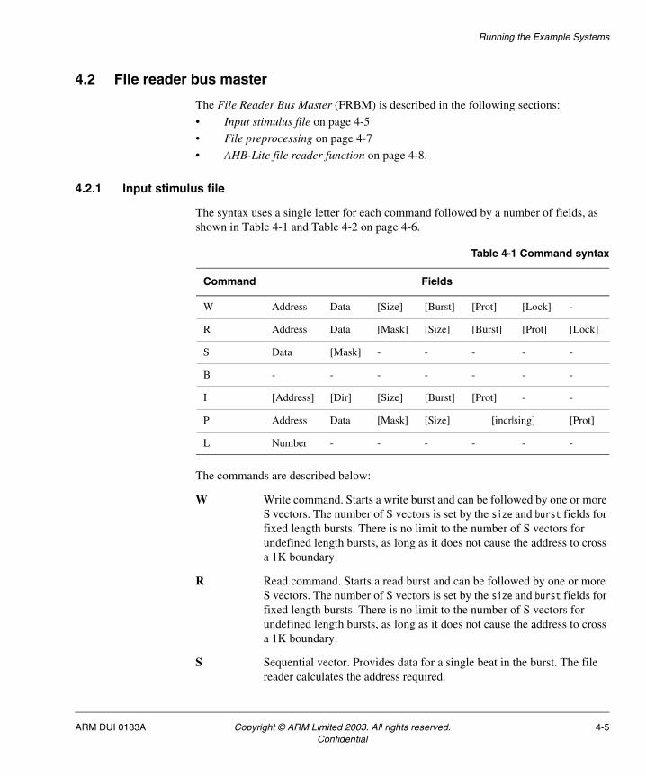
4.2.1 Input stimulus file
The syntax uses a single letter for each command followed by a number of fields, as shown in Table 4-1 and Table 4-2 on page 4-6.
The commands are described below:
W Write command. Starts a write burst and can be followed by one or more S vectors. The number of S vectors is set by the size and burst fields for fixed length bursts. There is no limit to the number of S vectors for undefined length bursts, as long as it does not cause the address to cross a 1K boundary.
R Read command. Starts a read burst and can be followed by one or more S vectors. The number of S vectors is set by the size and burst fields for fixed length bursts. There is no limit to the number of S vectors for undefined length bursts, as long as it does not cause the address to cross a 1K boundary.
S Sequential vector. Provides data for a single beat in the burst. The file reader calculates the address required.
Table 4-1 Command syntax
Command Fields
W Address Data [Size] [Burst] [Prot] [Lock] -
R Address Data [Mask] [Size] [Burst] [Prot] [Lock]
S Data [Mask] - - - - -
B - - - - - - -
I [Address] [Dir] [Size] [Burst] [Prot] - -
P Address Data [Mask] [Size] [incr|sing] [Prot]
L Number - - - - - -
ARM DUI 0183A Copyright © ARM Limited 2003. All rights reserved. 4-5Confidential

Running the Example Systems
B Busy command. Inserts a BUSY transfer mid burst. An INCR burst is allowed to have a busy after its last transfer (while the master determines whether or not it has another transfer to complete). It is not valid to have a busy command when a burst is not in progress.
I Idle command. Performs an idle transfer. The options enable you to set up the control information during the idle transfer.
P Poll command. Performs a read transfer that repeats until the data matches the required value. The poll vector can only be used for INCR or SINGLE burst types.
L Loop command. Repeats the last command a number of times. An L command can only follow a W or R when the burst type is INCR or SINGLE.
Table 4-2 Command fields
Field Default Values Description
Address 0x00000000 A 32-bit hex value First address of burst. Compulsory field for read, write and poll commands.
Data N/A A 32-bit hex value Required data value. Compulsory field for read, write, sequential, and poll commands.
Mask 0xFFFFFFFF A 32-bit hex value Bit mask, allows read data to be masked when tested against the required data.
Size size32 b | byte | h | hword | w | word | size8 | size16 | size32
Data size used for read or write transfers.
Burst Incr sing | single | incr | incr4 | wrap4 | incr8 | wrap8 | incr16 | wrap16
Burst type used for read or write transfers.
Prot 0000 A 4-bit binary value Direct representation of the MPROT value for the transfer.
Lock Nolock nolock | lock Indicate if the transfer is locked or not.
Dir Read read | write Indicates the value of MWRITE during an Idle command.
Number N/A 0 to 1024 Loop repeat value. Max value defined by number of bits used for of counter in File Reader.
Comment Delimiter
; | # | // | -- All common comment delimiters are valid.
4-6 Copyright © ARM Limited 2003. All rights reserved. ARM DUI 0183AConfidential

Running the Example Systems
4.2.2 File preprocessing
The stimulus file format is converted using a script (filereadconv) into a format that can be fed directly into the HDL code. The script is used to ensure the syntax of the input file is correct, and offers useful error messages when the syntax is not correct. Figure 4-1 shows the file preprocessing sequence.
Figure 4-1 File preprocessing
Additional error checks are performed by the script to ensure correct file reader operation:
• input file is readable (exists and has correct permissions)
• no unrecognized commands within the file
• no required fields that are missing or in the wrong format
• no S vectors before a defined-length or undefined-length burst has started
• no B vectors before a defined-length or undefined-length burst has started
• for poll commands, burst types are either INCR or SINGLE
• no incompatible commands inside a burst (write, read, idle, or poll)
• loop command has number specified
• Loop number field out of range [1 to 1023], set by 10-bit counter in AHB file reader bus master
• loop number does not exceed number of remaining transfers, for each defined-length burst type
• Size value does not exceed the data bus width. Max value is word | size32 for the file reader
RTL bus master HDL
Input stimulus
file format
File conversion
utility
fileconv.pl
.frd
file format
behavioral .frd
HDL file reader
ARM DUI 0183A Copyright © ARM Limited 2003. All rights reserved. 4-7Confidential

Running the Example Systems
• burst does not exceed 1KB address boundary, for both defined and undefined-length bursts.
• address is word-aligned, for word transfers
• address is half-word-aligned, for half-word transfers.
A warning is generated (file conversion continues) if:
• an optional field has an invalid value
• the number of S vectors following a W | R command is less than required for a fixed length burst (a burst is terminated early). This allows the simulation of early-terminated bursts.
Note
This script does not implement any unfolding of loops or address calculations. This is part of the file reader functionality. The conversion from text to a list of 32-bit hex numbers is a one-to-one mapping.
4.2.3 AHB-Lite file reader function
The AHB-Lite file reader has the following commands:
Write command Cycle 1 The file reader sets up the control signals from the command and MWRITE is asserted. MTRANS is set to NONSEQUENTIAL indicating the start of a new transfer, the Data field is stored ready to be output during the Data phase. Cycle 2 If MREADY is asserted, the file reader proceeds to the second control phase. If Burst is not a single transfer, the file reader calculates the next address based on Size and Burst values. The new address is output and MTRANS is set to SEQUENTIAL. This is the first Data phase where the Data is output for the previous address value.
Read command Cycle 1 The file reader sets up the control signals from the command and MWRITE is de-asserted. MTRANS is set to NONSEQUENTIAL indicating the start of a new transfer. Cycle 2 If MREADY is asserted, the file reader proceeds to the next control phase. If Burst is not a single transfer, the file reader calculates the next address based on Size and Burst values. The new address is output and MTRANS is set to SEQUENTIAL. The data is read for the previous address value and is compared with the Data field after applying the Mask. Differences between the expected and read data are reported to the simulation environment.
4-8 Copyright © ARM Limited 2003. All rights reserved. ARM DUI 0183AConfidential

Running the Example Systems
Sequential commandA sequential command is valid when a burst transfer has been started by a read or write command.
Cycle n Address set to calculated value and MTRANS is set to SEQUENTIAL.
Cycle n+1 For a write burst the Data field is read and output by the file reader. The Mask field is ignored. For a read burst the Data field is compared with the input data after the Mask has been applied. Differences between the expected and read data are reported to the simulation environment.
Busy command A busy command is valid when a burst transfer has been started by a read or write command:
Cycle n Address set to calculated value and MTRANS is set to BUSY.
Cycle n+1 Data is ignored.
Idle command The file reader sets MTRANS to IDLE and sets the control signals to the default values except for those with values specified in the command.
Poll command The file reader sets up a read of a single Address and reads in the data, on the following cycle. If the data read matches the Data field, the file reader continues to the next command, otherwise the file reader repeats the read from the same address.
Loop command The file reader is responsible for storing the last command and being able to repeat it a number of times. The file reader constrains the field value to 1024 because it uses a 10-bit counter.
The file reader is synchronous with the AHB bus clock signal, HCLK and is reset by the AHB reset signal HRESETn.
In accordance with the current Micropack EASY system, the file reader is little-endian. For documentation on endianness, see the AMBA Specification.
When MERROR is asserted indicating an error response from the slave, the file reader continues with the current transfer. No attempt is made to retransmit the erroneous transfer. The slave error response is reported to the simulation environment.
ARM DUI 0183A Copyright © ARM Limited 2003. All rights reserved. 4-9Confidential

Running the Example Systems
4-10 Copyright © ARM Limited 2003. All rights reserved. ARM DUI 0183AConfidential

Chapter 5Creating a Custom System
This chapter explains how to create your own ADK system, based on the example system provided. It contains the following sections:
• Adding new AMBA peripherals on page 5-2
• Creating a testbench on page 5-4
• Simulating the testbench on page 5-6.
ARM DUI 0183A Copyright © ARM Limited 2003. All rights reserved. 5-1Confidential

Creating a Custom System
5.1 Adding new AMBA peripherals
There are two main types of component within the ADK:
• those without subcomponents, such as the Watchdog
• those with subcomponents, such as the EASY_FRBM.
There are other subtle variations. Some directories can contain multiple components (such as ElementsAHB), and top-level directories (such as testbench) include an extra integration directory where the simulations are run.
The simplest way to install a new component is to copy an existing directory structure which most closely matches the structure of the new component.
Note
For all synthesizable components, the synthesis scripts held in the synopsys/scripts area must be renamed and changed.
Depending on the type of component, there are four procedures for adding new AMBA peripherals:
• Simple component on page 5-2
• Multiple components on page 5-3
• Structural component (EASY system) on page 5-3
• Structural component (testbench) on page 5-3.
5.1.1 Simple component
The following aspects are applicable to a simple component:
Features Single component, component name matches the directory name, no subcomponents.
Copy from Watchdog
Changes The PERIPH macro must be changed in several makefiles, the MODULES macro must be changed in the makefile in the rtl_source and netlist directories, and many macros must be changed in the synopsys makefile (if synthesizable).
If the component is to be included within a higher-level structural component, the following are required:
• add the PERIPH name to the Components_<topname>.mk file for the structural component
• for VHDL, a library call to the PERIPH region must be added to the structural component itself.
5-2 Copyright © ARM Limited 2003. All rights reserved. ARM DUI 0183AConfidential

Creating a Custom System
5.1.2 Multiple components
The following aspects are applicable to multiple components:
Features Multiple components, component names do not match the directory name, no subcomponents.
Copy from ElementsAHB
Changes The PERIPH macro must be changed in several makefiles, the MODULES macro must be changed in the makefile in the rtl_source and netlist directories to point to all source files relating to all components, and many macros must be changed in the synopsys makefile (if synthesizable).
Note
The netlist target issues a series of commands to the component target, one for each component in the area.
5.1.3 Structural component (EASY system)
The following aspects are applicable to EASY system structural components:
Features Single component, component name matches the directory name, contains subcomponents.
Copy from EASY_FRBM
Changes The PERIPH macro must be changed in several makefiles, the MODULES macro must be changed in the makefile in the rtl_source and netlist directories to point to all source files relating to all components, and a new Components_<blockname>.mk file must be created. This contains a list of the subcomponents of the system, in compile order (bottom-up) if applicable. Many macros must be changed in the synopsys makefile (if synthesizable).
5.1.4 Structural component (testbench)
The following aspects are applicable to testbench structural components:
Features Possibly multiple components, component name might or might not match the directory name, contains subcomponents.
Copy from TBEasy_FRBM
Changes The PERIPH macro must be changed in several makefiles, and the MODULES macro must be changed in the makefile in the rtl_source directory to point to all source files relating to all components.
ARM DUI 0183A Copyright © ARM Limited 2003. All rights reserved. 5-3Confidential

Creating a Custom System
5.2 Creating a testbench
An ADK testbench is usually a simple piece of structural HDL code. It instantiates the component under test (such as an EASY system), and any other models required for the testing of that component (such as external memories). The testbench can also contain behavioral or RTL HDL code itself (such as a simple function to provide a free-running clock).
Note
Because testbenches are not usually synthesizable, the usual design restrictions applied to RTL code might not apply.
The testbenches supplied with ADK are organized as follows:
• For each EASY system there is an associated testbench directory (such as $ADK/design/TBEasy_FRBM). This directory contains all testbenches associated with that EASY system.
• For EASY_ARM7 there is a testbench for standard operation, and a testbench for TIC testing of the ARM7 core. It is recommended that this approach is followed for new core-based EASY systems, mainly for consistency.
To create a new testbench, start by copying an existing testbench. The directory structure for the TBEasy_FRBM area is shown in Figure 5-1.
Figure 5-1 Directory structure for TBEasy_FRBM area
Note
The makefiles in each directory might require updating. See Structural component (testbench) on page 5-3 for more details.
$ADK/design/TBEasy_FRBM
verilog
rtl_source
vhdl
rtl_source
integration
frbmtests
verilog
vhdl
5-4 Copyright © ARM Limited 2003. All rights reserved. ARM DUI 0183AConfidential

Creating a Custom System
The testbench contains the following subdirectories:
$ADK/design/TBEasy_FRBM
For each testbench, a Components file must exist in this directory (for example, Components_TBEasy_FRBM.mk). This lists the component areas containing the immediate subcomponents of the testbench. For example, Components_TBEasy_FRBM.mk lists Tube and EASY_FRBM. When running a simulation, the relevant Components file is selected according to the setting of the $TEST_BENCH environment variable (that is, Components_${TEST_BENCH}.mk) and therefore the spelling and case of the testbench name must remain constant in all places where it occurs.
integration/frbmtests
File Reader Bus Master tests relevant to this system.
integration/verilog, integration/vhdl
For each type of simulation run, a directory is created in the relevant directory. For simulations of the HDL source, the run directory is created in the integration/$HDL_SOURCE directory. For simulations of the post-synthesis netlist, the run directory is created in the integration/$HDL_NETL directory.
verilog/rtl_source, vhdl/rtl_source
These contain the HDL source files for the testbench. Most testbenches supplied with ADK comprise a single local file (such as TBEasy_FRBM.vhd), but other components can be included in these directories. Ensure that these extra files are listed in the MODULES macro definition in the local makefile.
ARM DUI 0183A Copyright © ARM Limited 2003. All rights reserved. 5-5Confidential

Creating a Custom System
5.3 Simulating the testbench
Four environment variables are used to select the testbench environment, and the test to be run:
• TEST_ENV
• TEST_BENCH • TEST_NAME
• TEST_NAME_ROM.
Defaults for these are set in the file $ADK/design/sourceMe.
TEST_ENV Describes the type of test to be compiled for the bus master in the EASY system under test.
TEST_BENCH The name of the top-level testbench.
TEST_NAME The name of the test to be run.
TEST_NAME_ROM The name of the software to be run on the core.
Each of these environment variables can either be set using setenv prior to issuing the make command to run a simulation, or can be overridden as macro definitions on the make command line, for example:
make TEST_NAME=MyTest rtl
To run a simulation, follow the procedure described in Running integration tests on HDL source on page 2-6. For example, to run the new test MyTest on the HDL source of the new testbench TBnew, contained in the directory area TBnew:
cd $ADK/design/TBnew/integration
setenv TEST_NAME MyTest
setenv TEST_BENCH TBnew
make rtl
or:
cd $ADK/design/TBnew/integration
make TEST_NAME=MyTest TEST_BENCH=TBnew rtl
5-6 Copyright © ARM Limited 2003. All rights reserved. ARM DUI 0183AConfidential

Appendix AMakefile Structure
This appendix shows the structure of the makefiles supplied with the AMBA Design Kit (ADK). It contains the following sections:
• Introduction on page A-2
• Environment variables and makefile macros on page A-4
• Makefiles for an example component on page A-6
• Makefiles for a structural component on page A-12.
ARM DUI 0183A Copyright © ARM Limited 2003. All rights reserved. A-1Confidential
Makefile Structure
A.1 Introduction
To ensure the makefile structure is as simple as possible, the following design aspects are applied:
Make commands.
The make netlist command from the top-level of a component prepares the HDL netlist files for simulation. This target was necessary to allow sufficient differentiation for the setup of the Cadence simulation files. To synthesize a component or a system, a make netlist command must be issued within the synopsys subdirectory.
Component type
The boundaries between subcomponent, EASY system, and testbench have been clarified. ADK supports two types of component:
• those with no subcomponents (such as Watchdog and ElementsAHB)
• those with subcomponents (such as EASY_FRBM and TBEasy_FRBM).
The global scripts for the latter are combined, instead of using separate EASY and TB variants.
TestbenchesTestbenches for a given system are placed in separate areas. The following testbenches can be set up by sourcing the relevant file:
• $ADK/design/TBEasy_FRBM/sourceMe.TBEasy_FRBM
• $ADK/design/TBEasy_ML/sourceMe.TBEasy_ML
• $ADK/design/TBEasy_ARM7/sourceMe.TBEasy_ARM7
• $ADK/design/TBEasy_ML/sourceMe.TBEasy_ML_TIC
• $ADK/design/TBEasy_ARM7/sourceMe.TBEasy_ARM7_TIC.
Environment settings
Configuration is achieved using UNIX environment variables and makefile macros. The macros TEST_ENV, TEST_BENCH, TEST_NAME, and TEST_NAME_ROM are specified as environment variables, in addition to being specified on the make command line.
Macro clarificationThe makefiles contain a number of macros which are used throughout the structure of a component (such as PERIPH and MODULES). Effort has been made to clarify these, particularly PERIPH.
A-2 Copyright © ARM Limited 2003. All rights reserved. ARM DUI 0183AConfidential

Makefile Structure
The ADK makefile structure is designed to allow common actions (such as simulation and synthesis) to be performed using simple commands. Configuration of the action to be performed is achieved in two ways:
• UNIX environment variables describing the overall state of the project, for example, whether the HDL source is VHDL or Verilog.
• Command-line options to the make command, for example, extra options to pass to the simulator command-line.
Makefiles within the subdirectories of an ADK component contain information specific to that component. The actual rules, which are common to all components, are then stored in makefile fragments (indicated by a .mk suffix) within the global area, pointed to by the environment variable $GLOBAL. These files are called from the component-specific makefiles by the use of include statements.
Note
Most users are only likely to run make from a top-level EASY world for synthesis (for example, $ADK/design/EASY_FRBM/synopsys), or a testbench area for simulation (for example, $ADK/design/TBEasy_FRBM/integration).
ARM DUI 0183A Copyright © ARM Limited 2003. All rights reserved. A-3Confidential
Makefile Structure
A.2 Environment variables and makefile macros
A number of UNIX environment variables specify the parameters for a given session. Within the makefiles, macros specify component-specific information. Environment variables are set using the UNIX setenv command, and defaults are set within the file:
$ADK/design/sourceMe
Macros are set within makefiles, but can be overridden at the make command line. For example, to force a ModelSim simulation to execute in batch mode rather than interactive mode, the -c switch can be passed using the SIM_FLAGS macro:
make SIM_FLAGS=-c rtl
A.2.1 Environment variables
This section describes the most commonly used environment variables in ADK.
ADK Indicates the installed location of the ADK deliverables. Must not be changed.
ADSCODE Indicates the location of the example software for core-based EASY systems.
ADSUNIX Indicates whether UNIX or Windows version of ADS is used to compile the EASY software.
GLOBAL Indicates the installed location of the ADK global scripts and components. Must not be changed.
SIMULATOR Indicates which simulator tool to use. Supported options are modelsim (Mentor ModelSim) and LDV (Cadence LDV).
LDVSIMULATOR When SIMULATOR is set to LDV, this indicates which LDV tool to use. Supported options are ncverilog and verilog (which invokes the Verilog-XL simulator).
TEST_METH Selects whether the synthesized netlist is scan-enabled or not. If set to noscan, no scan insertion or scan-related activities are performed. If set to scaninsert, scan-enabled d-types are used in the design, a scan chain is inserted, and basic scan coverage is reported.
HDL_SOURCE Selects whether the source code is to be VHDL or Verilog.
HDL_NETL Selects the HDL type for the synthesized netlists. Currently, ADK only officially supports Verilog output from Synopsys. Setting HDL_NETL to vhdl is not guaranteed to work.
PERIPH Used throughout the makefile system, and is overridden in the local makefiles. A dummy value is set here to aid debugging when adding new peripherals.
A-4 Copyright © ARM Limited 2003. All rights reserved. ARM DUI 0183AConfidential

Makefile Structure
A.2.2 Macros
This section describes the macros used in the ADK:
PERIPH Specifies the top-level directory name (under $ADK/design/) of the current component.
SIM_FLAGS Allows command-line options to be passed to the simulation command.
ARM DUI 0183A Copyright © ARM Limited 2003. All rights reserved. A-5Confidential

Makefile Structure
A.3 Makefiles for an example component
Most components within ADK are stored in their own subdirectory. For example, the Watchdog component is stored in the following directory:
$ADK/design/Watchdog
All single ADK subcomponents conform to the structure given below. The directories containing makefile structures with slight differences are:
• ElementsAHB, ElementsAPB, InternalMemory, and ExternalMemory.
These directories contain multiple subcomponents which are grouped together for convenience. The makefiles reflect this, but otherwise use the same makefile fragments from the global area as the single ADK components.
• EASY directories (such as EASY_FRBM) and testbench directories (such as TBEasy_FRBM).
Top-level systems have different requirements to the subcomponents which they call. They have very similar makefile structures, but use different global makefile fragments which are designed to call the subcomponents from their own areas. Makefiles for these directories are described in a separate section.
The component-specific makefiles contained within the Watchdog area shown in Figure A-1 on page A-7.
A-6 Copyright © ARM Limited 2003. All rights reserved. ARM DUI 0183AConfidential

Makefile Structure
Figure A-1 Component-specific makefiles
These makefiles are described individually in the following subsections:
• Watchdog/makefile on page A-8
• Watchdog/synopsys/makefile on page A-8
• Watchdog/< HDL >/makefile on page A-10
• Watchdog/< HDL >/< rtl_source / netlist >/makefile on page A-10.
$ADK/design/Watchdog
synopsys
makefile
verilog
makefile
makefile
netlist
makefile
rtl_source
makefile
vhdl
makefile
netlist
makefile
rtl_source
makefile
ARM DUI 0183A Copyright © ARM Limited 2003. All rights reserved. A-7Confidential

Makefile Structure
A.3.1 Watchdog/makefile
File structure:
• Targets: all, rtl, netlist, clean
• Includes: none
• Component specific: none
The following targets are provided:
all Prepares the HDL source and (for a synthesizable component) netlist files for simulation. Equivalent to running make rtl then make netlist.
rtl Prepares the HDL source files for simulation. Issues a make rtl command in the relevant HDL directory (vhdl or verilog, determined by the $HDL_SOURCE environment variable).
netlist Prepares the HDL netlist files for simulation. Issues a make netlist command in the relevant HDL directory (vhdl or verilog, determined by the $HDL_NETL environment variable).
clean Removes temporary files from the vhdl, verilog, and synopsys areas. Issues a make clean command in the vhdl, verilog, and synopsys directories. Does not remove simulation log files, synthesis log and report files, synthesized netlist and .db (Synopsys database) files.
A.3.2 Watchdog/synopsys/makefile
File structure:
• Targets: netlist, clean
• Includes: $GLOBAL/synopsys_shared/SynMakefile.mk
• Component specific: sets the following macros:
• PERIPH The name of the directory (within $ADK/design) in which the component resides.
• TOP_NAME The name of the component to be synthesised
• OTHER_NAMES Names of HDL subcomponents which are stored within the same area
• COMMON_CELLS Names of HDL subcomponents which are stored in the $GLOBAL/$HDL_SOURCE directory (The Watchdog does not contain any of these. See the relevant makefile for the EgMaster component for an example). Common cells are treated exactly like all other HDL source for the subcomponent during simulation and synthesis.
A-8 Copyright © ARM Limited 2003. All rights reserved. ARM DUI 0183AConfidential

Makefile Structure
• SPECIAL_CELLS Names of HDL subcomponents which are stored in the $GLOBAL/$HDL_SOURCE directory, and which are to be treated specially during synthesis. These components are synthesized separately and set as dont_touch, so that they are not flattened into the rest of the design. This is done for clock gates and other cells which need to be easily found in a finished netlist or layout.
• MODULE_TYPE One of APB_Slave, APB_Master, AHB_Slave, AHB_Master, CPU_Wrapper, Structural, or Other. These are used to configure the synthesis run, and remove the requirement to manually set constraints on some standard AMBA signals.
• USE_TRISTATES States whether the component (or any subcomponent) requires the use of tristate driver cells. Allowable values are on or off.
• USE_LATCHES States whether the component (or any subcomponent) requires the use of transparent latch cells. Allowable values are on or off.
The following targets are provided:
netlist The dependency for the netlist target is the final log file of the synthesis run. The filename for this is described using macros and environment variables as:log/$PERIPH_$TEST_METH_$HDL_SOURCE_$HDL_NETL_synth.log
The component will be synthesized if this does not exist, or resynthesized if any of the following are newer than the log file:
- component-specific synthesis scripts, stored in Watchdog/synthesis/scripts
- VHDL source files
- Verilog source files.
If none of these are newer but the component must be resynthesized (for example, because the previous synthesis job was cancelled after partial completion), the log file must be deleted manually. Note that make clean will not delete the log file.
clean Deletes the temporary files created during synthesis. Does not delete the log, report, or db directories and contents, or the synthesised netlists. These must be removed manually, if necessary.
ARM DUI 0183A Copyright © ARM Limited 2003. All rights reserved. A-9Confidential

Makefile Structure
A.3.3 Watchdog/< HDL >/makefile
The two files contained in this section are identical:
• Watchdog/verilog/makefile
• Watchdog/vhdl/makefile
File structure:
• Targets: all, rtl, netlist, clean
• Includes: $GLOBAL/$(SIMULATOR)/DirMakefile.mk
• Component specific: sets the following macro:
• DIRS A space-separated list of subdirectories containing HDL files. Always includes rtl_source, and also includes netlist if the component is synthesizable.
The following targets are provided:
all Prepares the HDL source and, for a synthesizable component, netlist files for simulation. Issues a make all command in the directories listed in $DIRS.
rtl Prepares the HDL source files for simulation. Issues a make all command in the rtl_source directory.
netlist Prepares the relevant HDL files for simulation. A make netlist command is issued in the netlist directory if present, otherwise in the rtl_source directory.
clean Removes compiled and temporary files from the source and netlist areas. Issues a make clean command in the directories listed in $DIRS.
A.3.4 Watchdog/< HDL >/< rtl_source / netlist >/makefile
This section contains four files:
• Watchdog/verilog/rtl_source/makefile
• Watchdog/vhdl/rtl_source/makefile
• Watchdog/verilog/netlist/makefile
• Watchdog/vhdl/netlist/makefile
These four files are identical, except for the setting of the $MODULES macro (see below). A nonsynthesizable component (for example, a behavioral component such as the Tube) does not have netlist directories.
A-10 Copyright © ARM Limited 2003. All rights reserved. ARM DUI 0183AConfidential

Makefile Structure
File structure:
• Targets: all, netlist, clean
• Includes: $(GLOBAL)/$(SIMULATOR)/RtlMakefile.mk
• Component specific: sets the following macro:
• MODULES A list of the HDL subcomponent files, including any stored in the global area. These must be listed in compile order (for example, lowest-level first) for ModelSim compilation to work. For netlist directories, only a single module is listed, in the form $(PERIPH)_$(TEST_METH)_$(HDL_SOURCE)_net.vhd, with .v suffix in verilog areas. This is the name of the synthesized netlist, based on the chosen environment.
The following targets are provided:
all Prepares the HDL source and (for a synthesizable component) netlist files for simulation.
netlist Prepares the files for netlist simulation.
clean Removes compiled and temporary files from the source and netlist areas.
ARM DUI 0183A Copyright © ARM Limited 2003. All rights reserved. A-11Confidential

Makefile Structure
A.4 Makefiles for a structural component
A structural component calls other subcomponents which are stored in their own areas within ADK. The makefile structure for the subdirectories containing such a system (for example, EASY_FRBM) is shown in Figure A-2.
Figure A-2 Makefiles for structural components
Structural systems which form the top-level for simulation (commonly referred to within the ADK documentation as testbenches) have a slightly different structure, as shown in Figure A-3 on page A-13. They are generally not synthesizable (and so do not contain synopsys or netlist directories), but do contain the additional integration area. This area is used to store the tests to be run on the design, and also contains the directories within which simulations are to be run.
$ADK/design/EASY_FRBM
synopsys
makefile
verilog
makefile
makefile
netlist
makefile
rtl_source
makefile
vhdl
makefile
netlist
makefile
rtl_source
makefile
A-12 Copyright © ARM Limited 2003. All rights reserved. ARM DUI 0183AConfidential

Makefile Structure
Figure A-3 Makefiles for structural components (top-level for simulation)
The differences to a subcomponent described in the following sections, using the TBEasy_FRBM area as an example (except for synthesis, where the EASY_FRBM area is used):
• TBEasy_FRBM/makefile on page A-14
• EASY_FRBM/synopsys/makefile on page A-14
• TBEasy_FRBM/integration/makefile on page A-14
• TBEasy_FRBM/integration/< HDL >/makefile on page A-15
• TBEasy_FRBM/integration/< HDL >/(rundir)/makefile on page A-16.
$ADK/design/TBEasy_FRBM
verilog
makefile
makefile
makefile
rtl_source
vhdl
makefile
makefile
rtl_source
integration
frbmtests
vhdl
verilog
ARM DUI 0183A Copyright © ARM Limited 2003. All rights reserved. A-13Confidential

Makefile Structure
A.4.1 TBEasy_FRBM/makefile
File structure:
• Includes: $GLOBAL/$SIMULATOR/StructMakefile.mk and$ADK/design/$PERIPH/Components_$TEST_BENCH.mk
TBEasyMakefile.mk contains extra commands to prepare the subcomponents of the design for simulation. The list of subcomponents is given in the Components_$TEST_BENCH.mk file.
This is the form to use for testbench directories, possibly containing multiple testbench components (for example, TBEasy_ARM7 containing TBEasy_ARM7 and TBEasy_ARM7_TIC), so that the setting of the TEST_BENCH environment variable picks up the correct file.
For directories containing a single structural component, not related to the TEST_BENCH environment variable, use the following form:
$ADK/design/$PERIPH/Components_$PERIPH.mk
A.4.2 EASY_FRBM/synopsys/makefile
File structure:
• Includes: $GLOBAL/synopsys_shared/StructSynMakefile.mk and$ADK/design/$PERIPH/Components_$TOP_NAME.mk
TOP_NAME is set to the name of the top-level component to be synthesized. For single-component areas this is the same as PERIPH.
StructSynMakefile.mk includes extra synthesis commands to synthesize the subcomponents of the design.
Note
The MODULE_TYPE of structural components must be set to Structural.
A.4.3 TBEasy_FRBM/integration/makefile
File structure:
• Targets: rtl, net_max, net_typ, net_min, clean
• Includes: none
• Component specific: sets the following macros:
• DIRS The list of subdirectories for this testbench area
• PERIPH The name of the directory (within $ADK/design) in which the component resides.
A-14 Copyright © ARM Limited 2003. All rights reserved. ARM DUI 0183AConfidential

Makefile Structure
The following targets are provided:
rtl Initiates a simulation using the RTL source. The HDL variant is determined by the HDL_SOURCE environment variable. The make command is propagated to the directory indicated by this variable.
net_max, net_typ, net_min
Initiates a simulation using the synthesised netlist(s). The HDL variant is determined by the HDL_NETL environment variable. The make command is propagated to the directory indicated by this variable. The suffix determines whether MAXimum, TYPical or MINimum timings are used from the SDF timing file.
clean Removes all temporary files from the simulation areas. Does not remove the simulation directories themselves, or the log files created by the simulation.
Note
A make clean command from the TBEasy_FRBM/integration area is the easiest way of clearing the entire ADK database of temporary files. The command also descends into every specified subcomponent and issues make clean commands there.
A.4.4 TBEasy_FRBM/integration/< HDL >/makefile
The two files contained in this section are identical:
• TBEasy_FRBM/integration/vhdl/makefile
• TBEasy_FRBM/integration/verilog/makefile
File structure:
• Targets: rtl, net_max, net_typ, net_min, clean
• Includes: $GLOBAL/$SIMULATOR/DirSimMakefile.mk
• Component specific: sets the following macro:
• PERIPH The name of the directory (within $ADK/design) in which the component resides.
The following targets are provided:
rtl, net_max, net_typ, net_min
Each of these targets has a similar effect. A make command is issued to compile the relevant HDL (netlist or RTL source) a simulation run directory is created, and a make command is issued within the run directory to initiate the simulation.
ARM DUI 0183A Copyright © ARM Limited 2003. All rights reserved. A-15Confidential

Makefile Structure
The run directory is given the following name:
For RTL simulations: $(HDL_NETL)/$(TEST_BENCH)_rtl
For Netlist simulations:$(HDL_NETL)/$(TEST_BENCH)_$(TEST_METH)_$(HDL_SOURCE)_net_max
clean Remove all temporary files from the simulation areas. Does not remove the simulation directories themselves, or the log files created by the simulation.
A.4.5 TBEasy_FRBM/integration/< HDL >/(rundir)/makefile
The simulation run directories each contain a makefile:
• TBEasy_FRBM/integration/vhdl/(rundir)/makefile
• TBEasy_FRBM/integration/verilog/(rundir)/makefile
These makefiles are a soft link to $GLOBAL/$SIMULATOR/SimMakefile.mk.
File structure:
• Targets: rtl, net_max, net_typ, net_min, clean
• Includes: $ADK/design/$PERIPH/Components_$TEST_BENCH.mk
• Component specific: none
The following targets are provided:
rtl, net_max, net_typ, net_min
Prepares all files required for simulation (such as file reader bus master stimulus files), issues make commands to other areas when necessary (for example, frbmtests), and issues the simulation command itself.
clean Remove all temporary files from the simulation area.
A-16 Copyright © ARM Limited 2003. All rights reserved. ARM DUI 0183AConfidential