amano â amano cincinnati, inc. 140 harrison avenue roseland, new jersey 07068 amano cincinnati,...
TRANSCRIPT
AMANO
MRX-35Electronic Calculating Time Recorder
Setup and Operations Manual
Proprietary Notice This document contains proprietary information and may not be reproduced in whole or in part without written permission from:
Amano Cincinnati, Inc. 140 Harrison Avenue Roseland, New Jersey 07068
Amano Cincinnati, Inc. reserves the right to make equipment changes and improvements which may not be reflected in this document. Portions of this document may have been updated to include the latest hardware or firmware versions.
We recommend that this document be read in its entirety before any attempt is made to operate the equipment.
MRX-35 i
Table of Contents
Chapter 1: Overview........................................................ 1-1Operation Summary ............................................................... 1-1External View.......................................................................... 1-3Button Functions..................................................................... 1-3The LCD Display .................................................................... 1-4
Normal Operation ..............................................................1-5Programming Mode...........................................................1-5
Other Components ................................................................. 1-6
Chapter 2: Getting Started.............................................. 2-1Placement/Location ................................................................ 2-1
Desktop Installation ...........................................................2-1Wall Mounting....................................................................2-2
Power Connection .................................................................. 2-4The Time Card........................................................................ 2-5How to Insert a Time Card...................................................... 2-7
Chapter 3: Programming ................................................ 3-1Introduction............................................................................. 3-1Programming Tips .................................................................. 3-1Basic Programming ................................................................ 3-2
Time Settings ....................................................................3-2Date Settings.....................................................................3-2Pay Period Type and End Day ..........................................3-3Daylight Saving Time ........................................................3-5Day Change Time .............................................................3-7Day Change Override........................................................3-8Time Rounding ................................................................3-10Automatic Break ..............................................................3-12Daily and Weekly Overtime .............................................3-15Imprint and Display Mode................................................3-18Date Print Mode ..............................................................3-19Fixed Break .....................................................................3-20Overtime Type.................................................................3-21Card Data Clear ..............................................................3-22Data Initialization .............................................................3-23
Advanced Programming ....................................................... 3-26Exception Zones..............................................................3-26Revision Zones................................................................3-35
ii MRX-35
Chapter 4: Maintenance and Troubleshooting ............. 4-1Cleaning (Exterior).................................................................. 4-1Top Cover Removal................................................................ 4-1Ribbon Replacement .............................................................. 4-2Fuse Replacement ................................................................. 4-4Troubleshooting...................................................................... 4-5Error Codes ............................................................................ 4-6Parameter Error Codes .......................................................... 4-7Replacement Parts and Accessories...................................... 4-8Default Programming Values.................................................. 4-9
Basic Programming ...........................................................4-9Advanced Programming..................................................4-10
Chapter 5: Specifications ............................................... 5-1
MRX-35 1-1
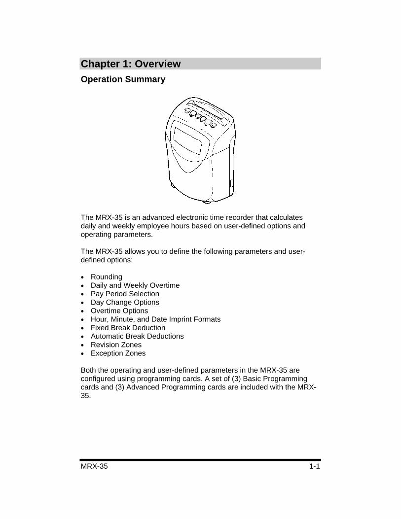
Chapter 1: Overview Operation Summary
The MRX-35 is an advanced electronic time recorder that calculates daily and weekly employee hours based on user-defined options and operating parameters.
The MRX-35 allows you to define the following parameters and user-defined options:
• Rounding• Daily and Weekly Overtime • Pay Period Selection • Day Change Options • Overtime Options • Hour, Minute, and Date Imprint Formats • Fixed Break Deduction • Automatic Break Deductions • Revision Zones • Exception Zones
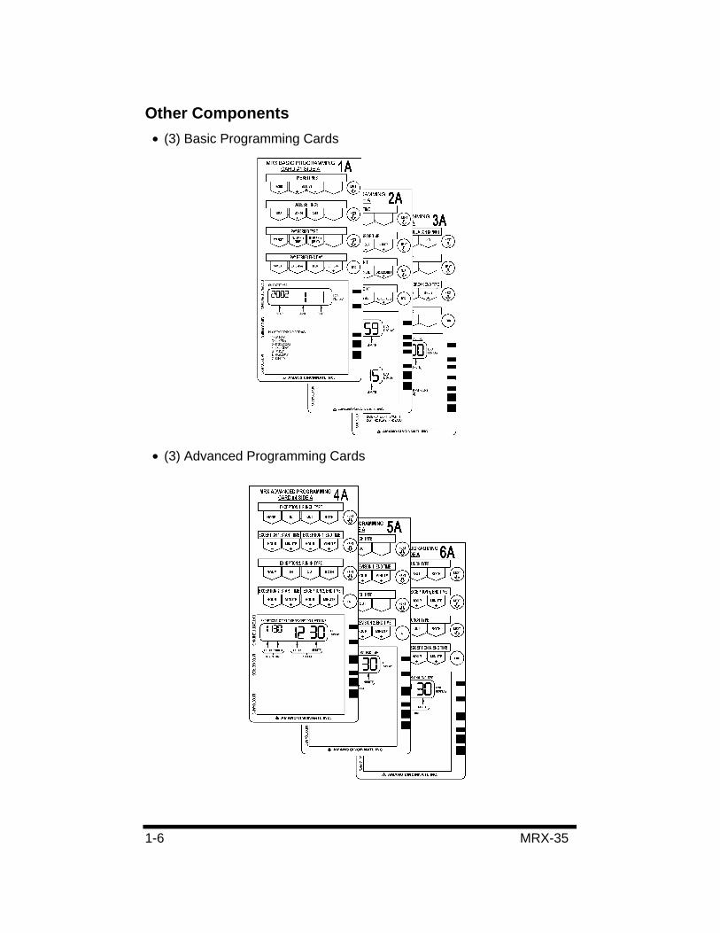
Both the operating and user-defined parameters in the MRX-35 are configured using programming cards. A set of (3) Basic Programming cards and (3) Advanced Programming cards are included with the MRX-35.
1-2 MRX-35
User enrollments (ID numbers) are not required for the MRX-35. Hours are stored for each user in the MRX-35 under a special user number that is encoded on both sides of the time card. This information is stored in the MRX-35 for two pay periods and then it is automatically deleted. This information can also be manually deleted by using one of the programming cards supplied with the MRX-35. When the programmed pay period has ended, a new time card must be issued. When a new time card is issued, the MRX-35 stores the data for the card under a new user number, therefore eliminating the need for enrollments.
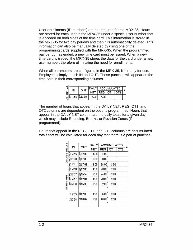
When all parameters are configured in the MRX-35, it is ready for use. Employees simply punch IN and OUT. These punches will appear on the time card in their corresponding columns.
The number of hours that appear in the DAILY NET, REG, OT1, and OT2 columns are dependent on the options programmed. Hours that appear in the DAILY NET column are the daily totals for a given day, which may include Rounding, Breaks, or Revision Zones (if programmed).
Hours that appear in the REG, OT1, and OT2 columns are accumulated totals that will be calculated for each day that there is a pair of punches.
MRX-35 1-3
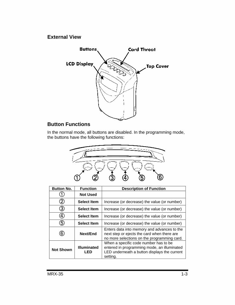
External View
Button Functions In the normal mode, all buttons are disabled. In the programming mode, the buttons have the following functions:
Button No. Function Description of Function Not Used
Select Item Increase (or decrease) the value (or number)
Select Item Increase (or decrease) the value (or number)
Select Item Increase (or decrease) the value (or number)
Select Item Increase (or decrease) the value (or number)
Next/End Enters data into memory and advances to the next step or ejects the card when there are no more selections on the programming card.
Not Shown Illuminated LED
When a specific code number has to be entered in programming mode, an illuminated LED underneath a button displays the current setting.
1-4 MRX-35
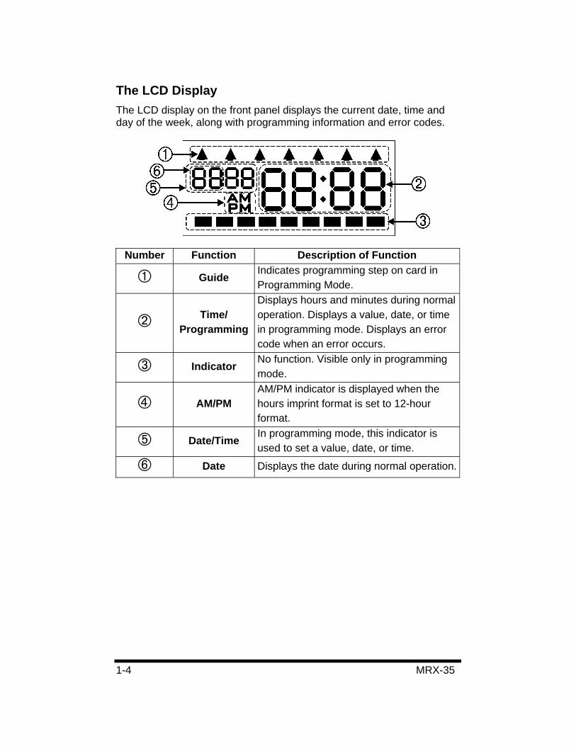
The LCD DisplayThe LCD display on the front panel displays the current date, time and day of the week, along with programming information and error codes.
Number Function Description of Function
Guide Indicates programming step on card in Programming Mode.
Time/Programming
Displays hours and minutes during normal operation. Displays a value, date, or time in programming mode. Displays an error code when an error occurs.
Indicator No function. Visible only in programming mode.
AM/PM AM/PM indicator is displayed when the hours imprint format is set to 12-hour format.
Date/Time In programming mode, this indicator is used to set a value, date, or time.
Date Displays the date during normal operation.
MRX-35 1-5
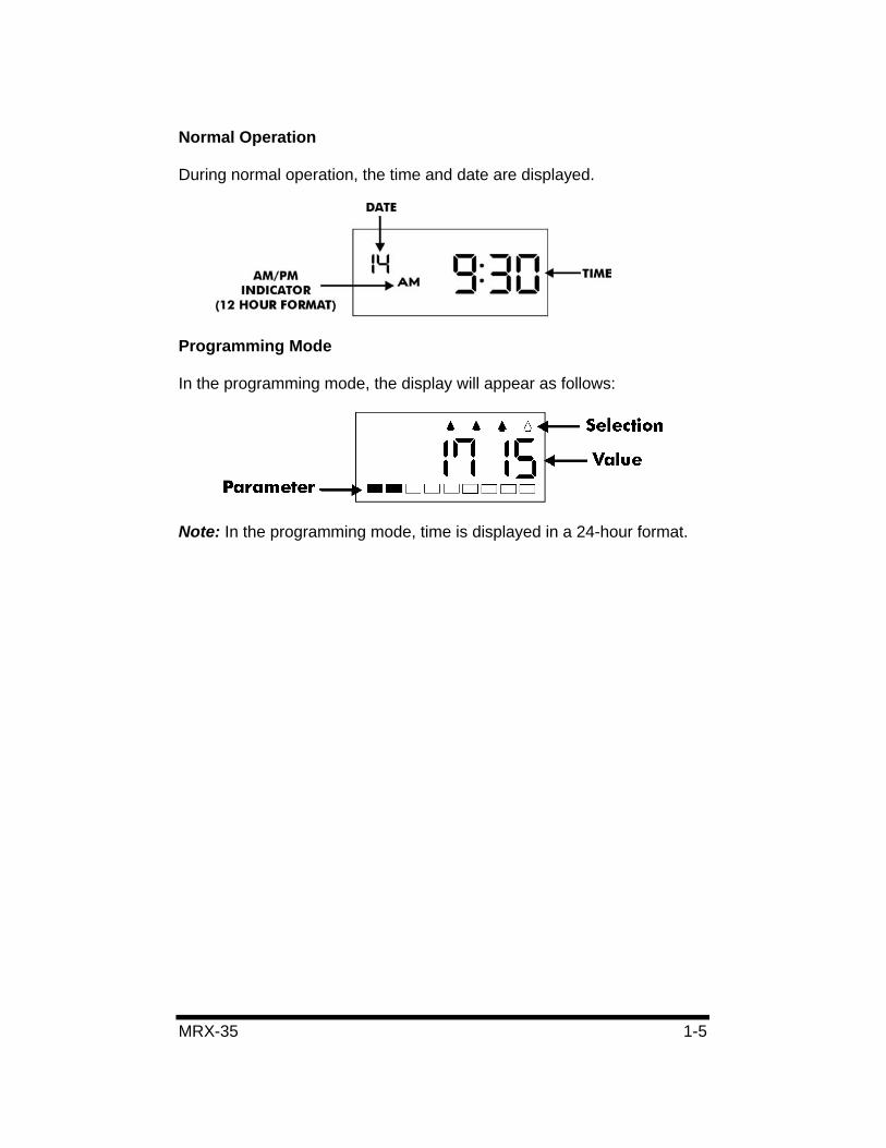
Normal Operation
During normal operation, the time and date are displayed.
Programming Mode
In the programming mode, the display will appear as follows:
Note: In the programming mode, time is displayed in a 24-hour format.
1-6 MRX-35
Other Components • (3) Basic Programming Cards
• (3) Advanced Programming Cards
MRX-35 2-1
Chapter 2: Getting Started
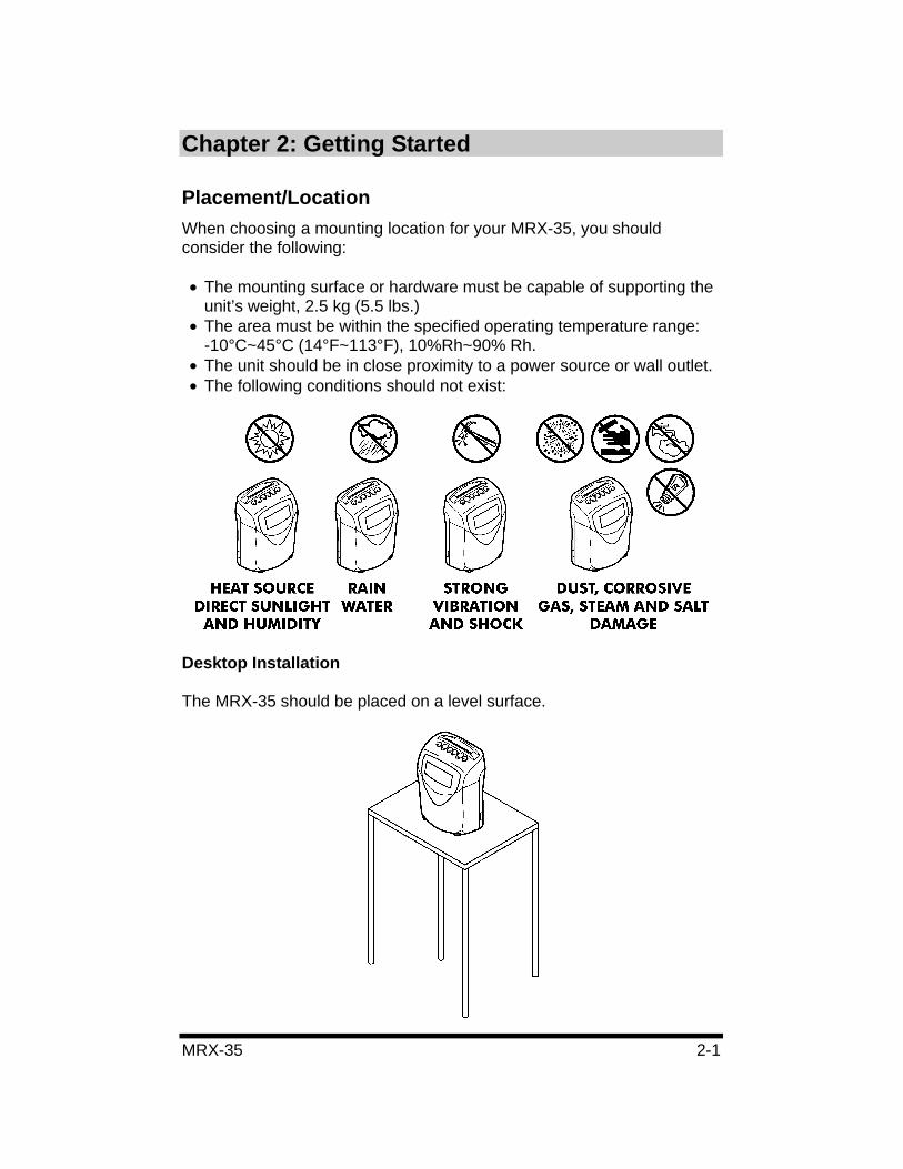
Placement/LocationWhen choosing a mounting location for your MRX-35, you should consider the following:
• The mounting surface or hardware must be capable of supporting the unit’s weight, 2.5 kg (5.5 lbs.)
• The area must be within the specified operating temperature range: -10°C~45°C (14°F~113°F), 10%Rh~90% Rh.
• The unit should be in close proximity to a power source or wall outlet. • The following conditions should not exist:
Desktop Installation
The MRX-35 should be placed on a level surface.
2-2 MRX-35
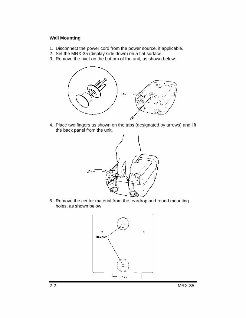
Wall Mounting
1. Disconnect the power cord from the power source, if applicable. 2. Set the MRX-35 (display side down) on a flat surface. 3. Remove the rivet on the bottom of the unit, as shown below:
4. Place two fingers as shown on the tabs (designated by arrows) and lift the back panel from the unit.
5. Remove the center material from the teardrop and round mounting holes, as shown below:
MRX-35 2-3
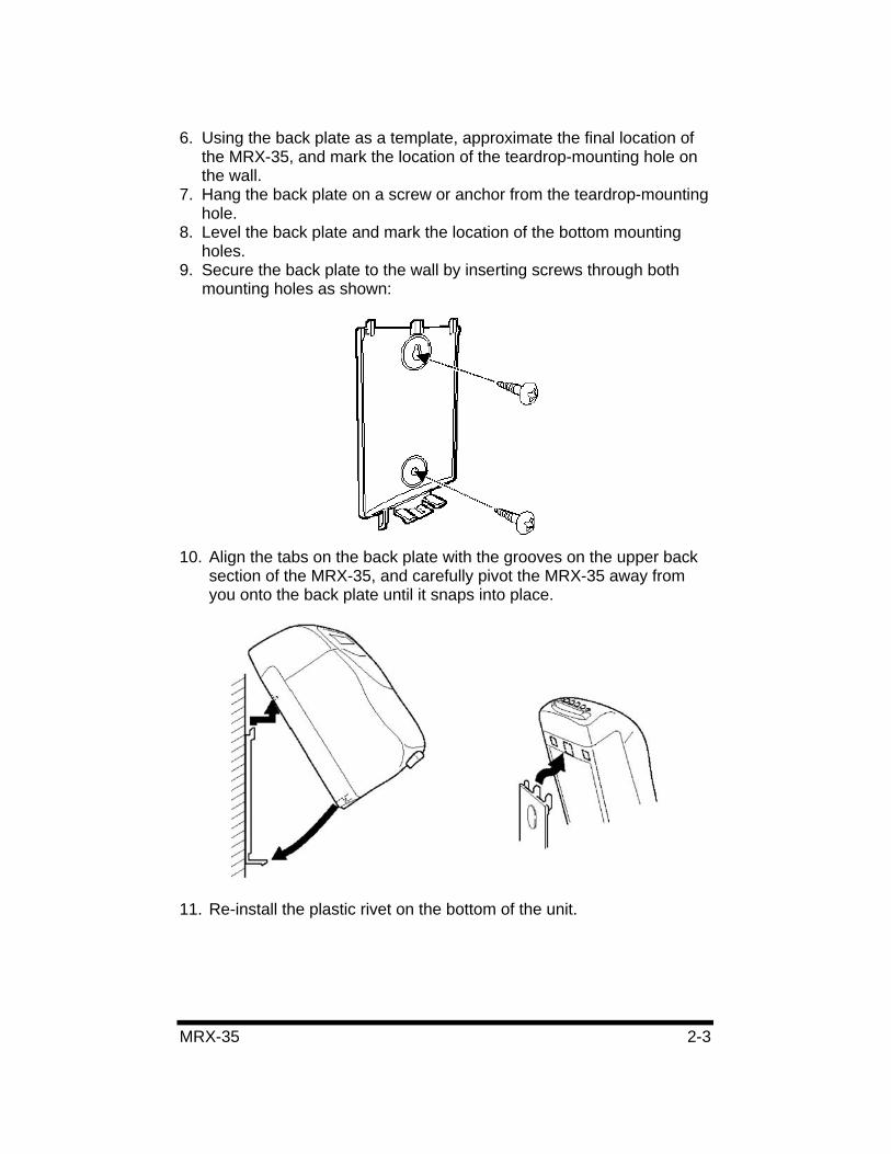
6. Using the back plate as a template, approximate the final location of the MRX-35, and mark the location of the teardrop-mounting hole on the wall.
7. Hang the back plate on a screw or anchor from the teardrop-mounting hole.
8. Level the back plate and mark the location of the bottom mounting holes.
9. Secure the back plate to the wall by inserting screws through both mounting holes as shown:
10. Align the tabs on the back plate with the grooves on the upper back section of the MRX-35, and carefully pivot the MRX-35 away from you onto the back plate until it snaps into place.
11. Re-install the plastic rivet on the bottom of the unit.
2-4 MRX-35
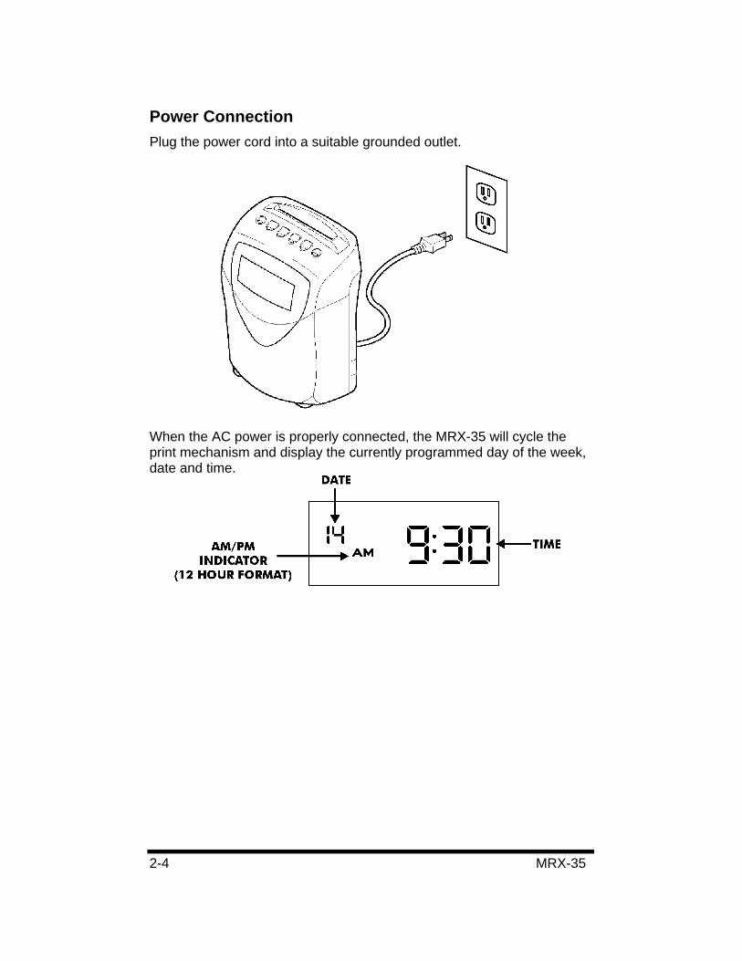
Power Connection Plug the power cord into a suitable grounded outlet.
When the AC power is properly connected, the MRX-35 will cycle the print mechanism and display the currently programmed day of the week, date and time.
MRX-35 2-5
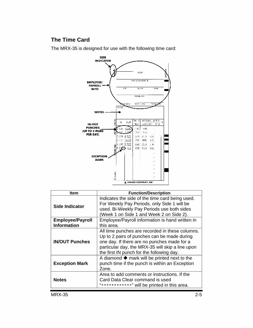
The Time Card The MRX-35 is designed for use with the following time card:
Item Function/Description
Side IndicatorIndicates the side of the time card being used. For Weekly Pay Periods, only Side 1 will be used. Bi-Weekly Pay Periods use both sides (Week 1 on Side 1 and Week 2 on Side 2).
Employee/Payroll Information
Employee/Payroll information is hand written in this area.
IN/OUT Punches
All time punches are recorded in these columns. Up to 2 pairs of punches can be made during one day. If there are no punches made for a particular day, the MRX-35 will skip a line upon the first IN punch for the following day.
Exception Mark A diamond mark will be printed next to the punch time if the punch is within an Exception Zone.
Notes Area to add comments or instructions. If the Card Data Clear command is used “************” will be printed in this area.
2-6 MRX-35
Item Function/Description
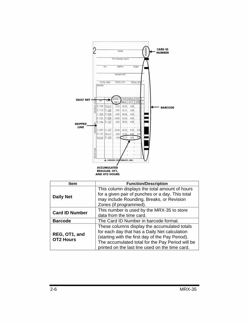
Daily NetThis column displays the total amount of hours for a given pair of punches or a day. This total may include Rounding, Breaks, or Revision Zones (if programmed).
Card ID Number This number is used by the MRX-35 to store data from the time card.
Barcode The Card ID Number in barcode format.
REG, OT1, and OT2 Hours
These columns display the accumulated totals for each day that has a Daily Net calculation (starting with the first day of the Pay Period). The accumulated total for the Pay Period will be printed on the last line used on the time card.
MRX-35 2-7
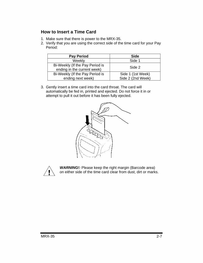
How to Insert a Time Card 1. Make sure that there is power to the MRX-35. 2. Verify that you are using the correct side of the time card for your Pay
Period:
Pay Period Side Weekly Side 1
Bi-Weekly (If the Pay Period is ending in the current week) Side 2
Bi-Weekly (If the Pay Period is ending next week)
Side 1 (1st Week) Side 2 (2nd Week)
3. Gently insert a time card into the card throat. The card will automatically be fed in, printed and ejected. Do not force it in or attempt to pull it out before it has been fully ejected.
WARNING!: Please keep the right margin (Barcode area) on either side of the time card clear from dust, dirt or marks.

2-8 MRX-35
MRX-35 3-1
Chapter 3: Programming Introduction The MRX-35 must be programmed and configured before use. Basic Programming consists of time, date, imprint, and display formatting, as well as Pay Period, Time Rounding, Auto Breaks, Fixed Break, Overtime, Daylight Saving Time (DST), and Day Change Time adjustments.
Advanced Programming mode involves creating Exception and Revision Zones. An Exception Zone prints a next to the punch time on the time card during a specified period. A Revision Zone “revises” a punch time (IN or OUT punch) inside a specific period to a pre-configured time to prevent employees from accumulating extra time by punching in early or punching out late. Up to (6) Exception and (6) Revision Zones can be programmed.
Programming Tips • To eject a programming card, you must advance though all of the
settings.
• To return to a previous programming step, you must advance through the card, re-insert the card and press the Next button until the desired step is reached.
• An illuminated LED underneath a button displays the current setting.
Time and Date Settings:
• Holding down each button indicated by the programming card will rapidly increase or decrease the values in the display.
• Start times and dates have to be entered first.• To disable a Break, Zone, Daily OT #1 and #2, or Weekly OT #1
and #2, press the Hours button and advance the hours display past “23” until it reaches “- - - - “.
• All times must be entered in 24-hour format.• For dates, each month is indicated by a number (January = 1).
3-2 MRX-35
Basic Programming Time Settings To set the time (Hours and Minutes), perform the following:
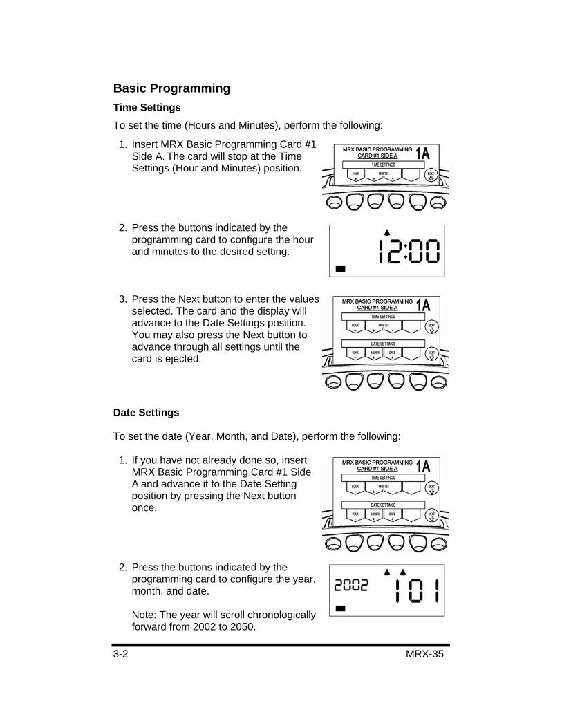
1. Insert MRX Basic Programming Card #1 Side A. The card will stop at the Time Settings (Hour and Minutes) position.
2. Press the buttons indicated by the programming card to configure the hour and minutes to the desired setting.
3. Press the Next button to enter the values selected. The card and the display will advance to the Date Settings position. You may also press the Next button to advance through all settings until the card is ejected.
Date Settings
To set the date (Year, Month, and Date), perform the following:
1. If you have not already done so, insert MRX Basic Programming Card #1 Side A and advance it to the Date Setting position by pressing the Next button once.
2. Press the buttons indicated by the programming card to configure the year, month, and date.
Note: The year will scroll chronologically forward from 2002 to 2050.
MRX-35 3-3
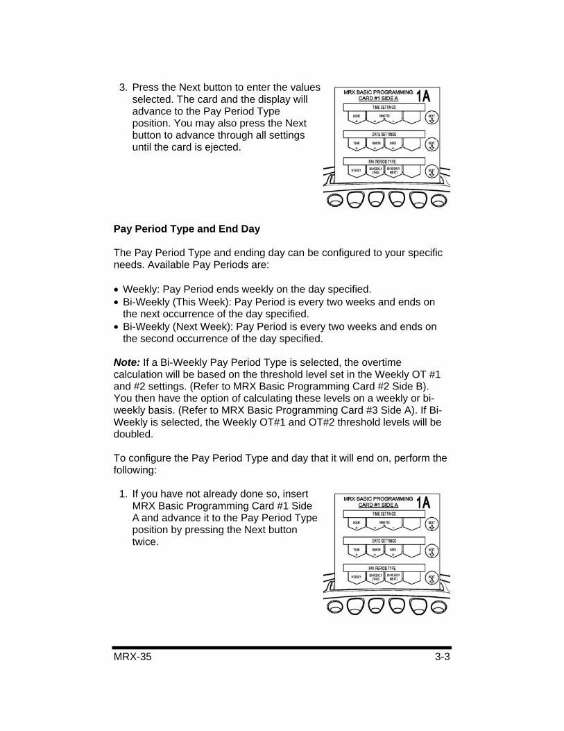
3. Press the Next button to enter the values selected. The card and the display will advance to the Pay Period Type position. You may also press the Next button to advance through all settings until the card is ejected.
Pay Period Type and End Day
The Pay Period Type and ending day can be configured to your specific needs. Available Pay Periods are:
• Weekly: Pay Period ends weekly on the day specified. • Bi-Weekly (This Week): Pay Period is every two weeks and ends on
the next occurrence of the day specified. • Bi-Weekly (Next Week): Pay Period is every two weeks and ends on
the second occurrence of the day specified.
Note: If a Bi-Weekly Pay Period Type is selected, the overtime calculation will be based on the threshold level set in the Weekly OT #1 and #2 settings. (Refer to MRX Basic Programming Card #2 Side B). You then have the option of calculating these levels on a weekly or bi-weekly basis. (Refer to MRX Basic Programming Card #3 Side A). If Bi-Weekly is selected, the Weekly OT#1 and OT#2 threshold levels will be doubled.
To configure the Pay Period Type and day that it will end on, perform the following:
1. If you have not already done so, insert MRX Basic Programming Card #1 Side A and advance it to the Pay Period Type position by pressing the Next button twice.
3-4 MRX-35
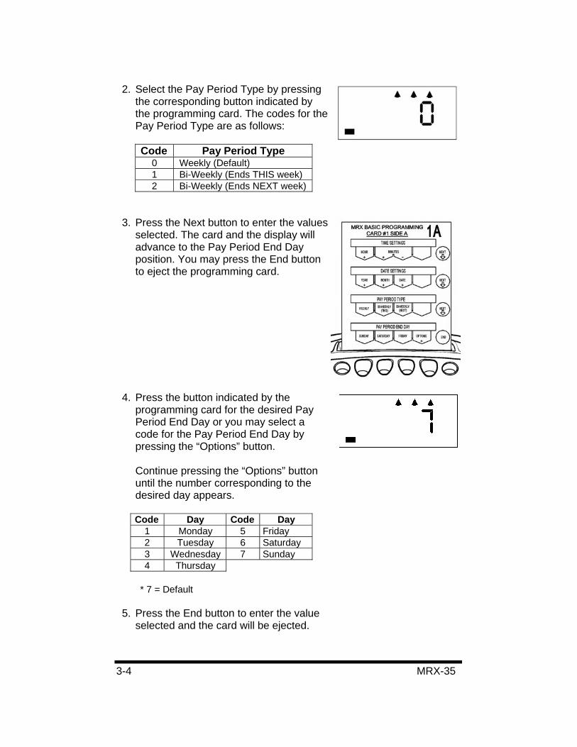
2. Select the Pay Period Type by pressing the corresponding button indicated by the programming card. The codes for the Pay Period Type are as follows:
Code Pay Period Type 0 Weekly (Default) 1 Bi-Weekly (Ends THIS week) 2 Bi-Weekly (Ends NEXT week)
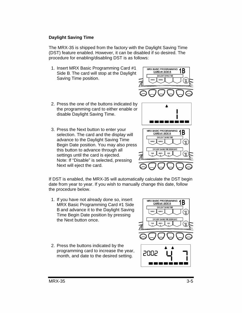
3. Press the Next button to enter the values selected. The card and the display will advance to the Pay Period End Day position. You may press the End button to eject the programming card.
4. Press the button indicated by the programming card for the desired Pay Period End Day or you may select a code for the Pay Period End Day by pressing the “Options” button.
Continue pressing the “Options” button until the number corresponding to the desired day appears.
Code Day Code Day 1 Monday 5 Friday 2 Tuesday 6 Saturday 3 Wednesday 7 Sunday 4 Thursday
* 7 = Default
5. Press the End button to enter the value selected and the card will be ejected.
MRX-35 3-5
Daylight Saving Time
The MRX-35 is shipped from the factory with the Daylight Saving Time (DST) feature enabled. However, it can be disabled if so desired. The procedure for enabling/disabling DST is as follows:
1. Insert MRX Basic Programming Card #1 Side B. The card will stop at the Daylight Saving Time position.
2. Press the one of the buttons indicated by the programming card to either enable or disable Daylight Saving Time.
3. Press the Next button to enter your selection. The card and the display will advance to the Daylight Saving Time Begin Date position. You may also press this button to advance through all settings until the card is ejected. Note: If “Disable” is selected, pressing Next will eject the card.
If DST is enabled, the MRX-35 will automatically calculate the DST begin date from year to year. If you wish to manually change this date, follow the procedure below.
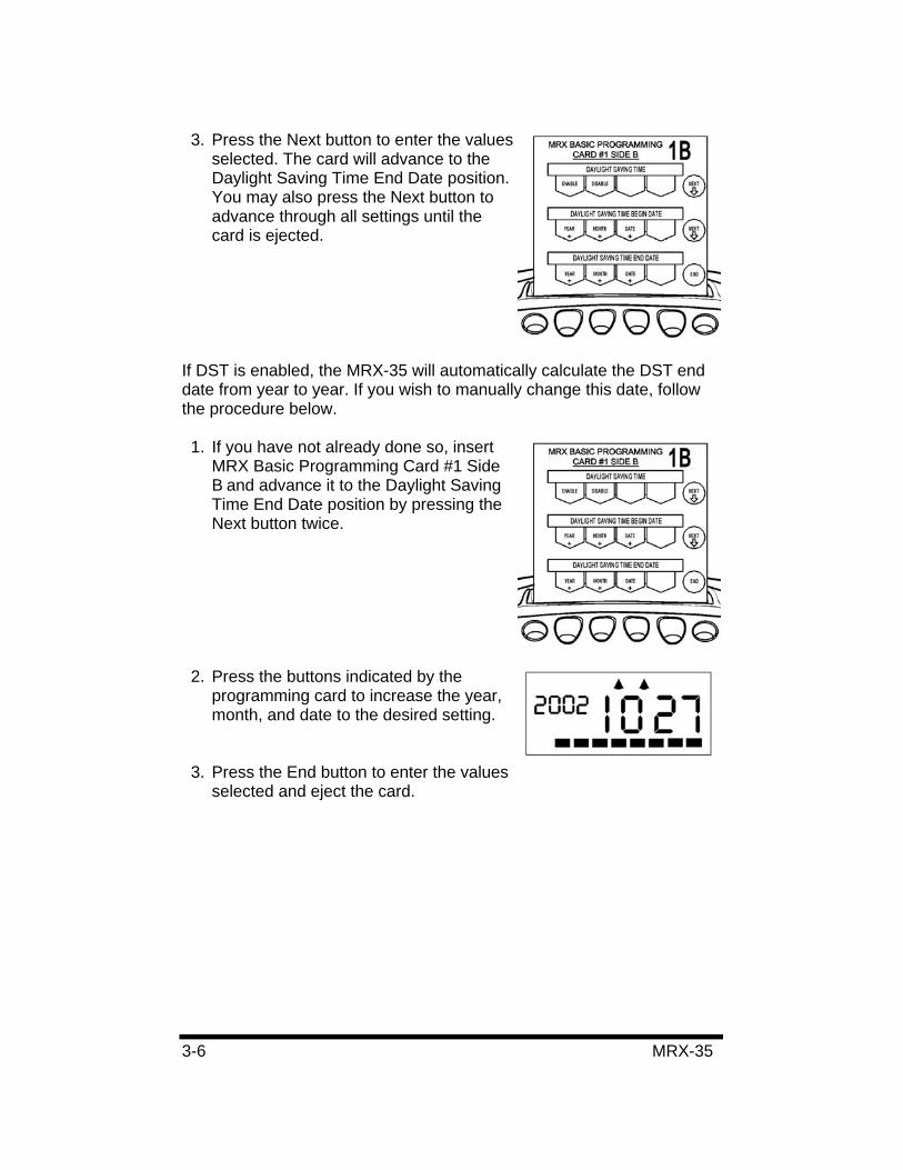
1. If you have not already done so, insert MRX Basic Programming Card #1 Side B and advance it to the Daylight Saving Time Begin Date position by pressing the Next button once.
2. Press the buttons indicated by the programming card to increase the year, month, and date to the desired setting.
3-6 MRX-35
3. Press the Next button to enter the values selected. The card will advance to the Daylight Saving Time End Date position. You may also press the Next button to advance through all settings until the card is ejected.
If DST is enabled, the MRX-35 will automatically calculate the DST end date from year to year. If you wish to manually change this date, follow the procedure below.
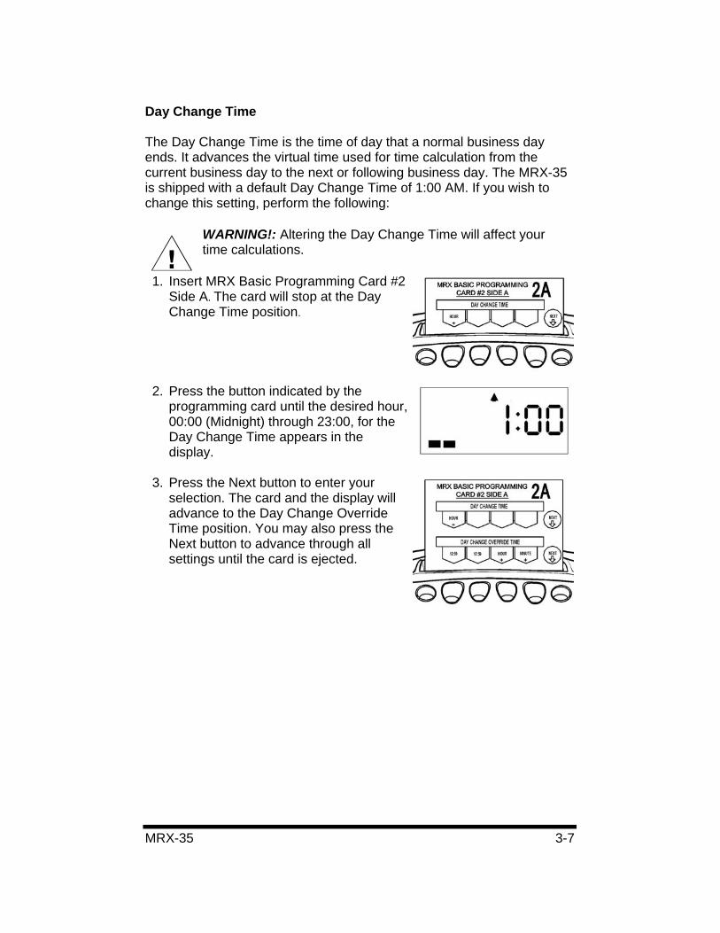
1. If you have not already done so, insert MRX Basic Programming Card #1 Side B and advance it to the Daylight Saving Time End Date position by pressing the Next button twice.
2. Press the buttons indicated by the programming card to increase the year, month, and date to the desired setting.
3. Press the End button to enter the values selected and eject the card.
MRX-35 3-7
Day Change Time
The Day Change Time is the time of day that a normal business day ends. It advances the virtual time used for time calculation from the current business day to the next or following business day. The MRX-35 is shipped with a default Day Change Time of 1:00 AM. If you wish to change this setting, perform the following:
WARNING!: Altering the Day Change Time will affect your time calculations.
1. Insert MRX Basic Programming Card #2 Side A. The card will stop at the Day Change Time position.
2. Press the button indicated by the programming card until the desired hour, 00:00 (Midnight) through 23:00, for the Day Change Time appears in the display.
3. Press the Next button to enter your selection. The card and the display will advance to the Day Change Override Time position. You may also press the Next button to advance through all settings until the card is ejected.
3-8 MRX-35
Day Change Override
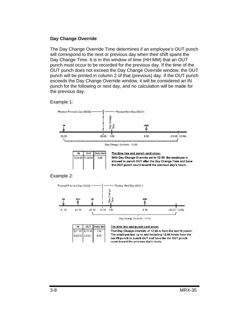
The Day Change Override Time determines if an employee’s OUT punch will correspond to the next or previous day when their shift spans the Day Change Time. It is in this window of time (HH:MM) that an OUT punch must occur to be recorded for the previous day. If the time of the OUT punch does not exceed the Day Change Override window, the OUT punch will be printed in column 2 of that (previous) day. If the OUT punch exceeds the Day Change Override window, it will be considered an IN punch for the following or next day, and no calculation will be made for the previous day.
Example 1:
Example 2:
MRX-35 3-9
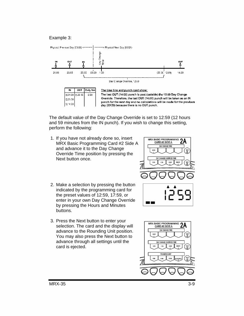
Example 3:
The default value of the Day Change Override is set to 12:59 (12 hours and 59 minutes from the IN punch). If you wish to change this setting, perform the following:
1. If you have not already done so, insert MRX Basic Programming Card #2 Side Aand advance it to the Day Change Override Time position by pressing the Next button once.
2. Make a selection by pressing the button indicated by the programming card for the preset values of 12:59, 17:59, or enter in your own Day Change Override by pressing the Hours and Minutes buttons.
3. Press the Next button to enter your selection. The card and the display will advance to the Rounding Unit position. You may also press the Next button to advance through all settings until the card is ejected.
3-10 MRX-35
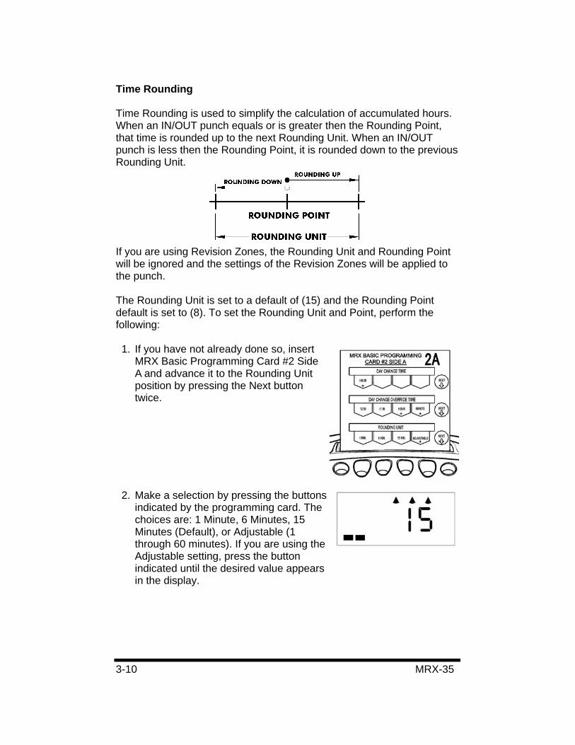
Time Rounding
Time Rounding is used to simplify the calculation of accumulated hours. When an IN/OUT punch equals or is greater then the Rounding Point, that time is rounded up to the next Rounding Unit. When an IN/OUT punch is less then the Rounding Point, it is rounded down to the previous Rounding Unit.
If you are using Revision Zones, the Rounding Unit and Rounding Point will be ignored and the settings of the Revision Zones will be applied to the punch.
The Rounding Unit is set to a default of (15) and the Rounding Point default is set to (8). To set the Rounding Unit and Point, perform the following:
1. If you have not already done so, insert MRX Basic Programming Card #2 Side A and advance it to the Rounding Unit position by pressing the Next button twice.
2. Make a selection by pressing the buttons indicated by the programming card. The choices are: 1 Minute, 6 Minutes, 15 Minutes (Default), or Adjustable (1 through 60 minutes). If you are using the Adjustable setting, press the button indicated until the desired value appears in the display.
MRX-35 3-11
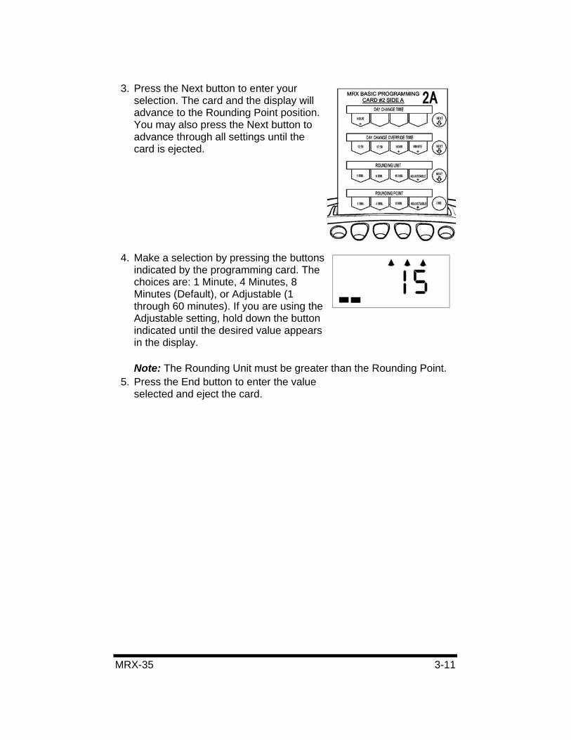
3. Press the Next button to enter your selection. The card and the display will advance to the Rounding Point position. You may also press the Next button to advance through all settings until the card is ejected.
4. Make a selection by pressing the buttons indicated by the programming card. The choices are: 1 Minute, 4 Minutes, 8 Minutes (Default), or Adjustable (1 through 60 minutes). If you are using the Adjustable setting, hold down the button indicated until the desired value appears in the display.
Note: The Rounding Unit must be greater than the Rounding Point.5. Press the End button to enter the value
selected and eject the card.
3-12 MRX-35
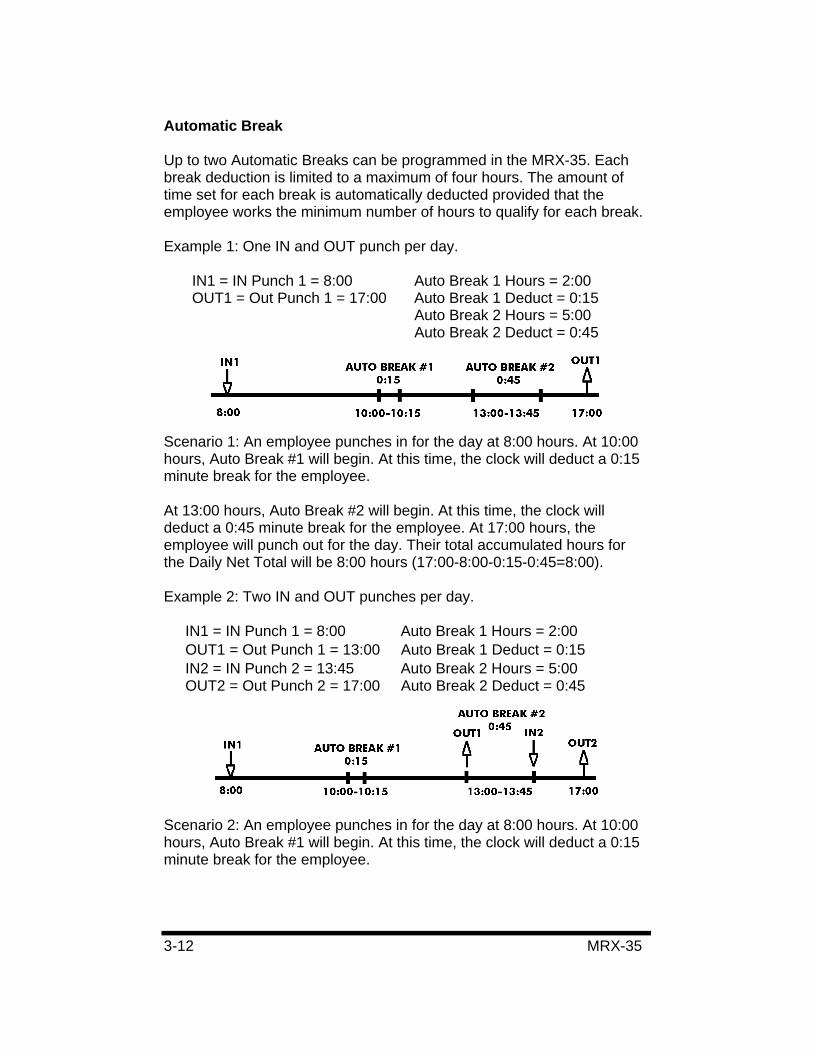
Automatic Break
Up to two Automatic Breaks can be programmed in the MRX-35. Each break deduction is limited to a maximum of four hours. The amount of time set for each break is automatically deducted provided that the employee works the minimum number of hours to qualify for each break.
Example 1: One IN and OUT punch per day.
IN1 = IN Punch 1 = 8:00 Auto Break 1 Hours = 2:00 OUT1 = Out Punch 1 = 17:00 Auto Break 1 Deduct = 0:15 Auto Break 2 Hours = 5:00 Auto Break 2 Deduct = 0:45
Scenario 1: An employee punches in for the day at 8:00 hours. At 10:00 hours, Auto Break #1 will begin. At this time, the clock will deduct a 0:15 minute break for the employee.
At 13:00 hours, Auto Break #2 will begin. At this time, the clock will deduct a 0:45 minute break for the employee. At 17:00 hours, the employee will punch out for the day. Their total accumulated hours for the Daily Net Total will be 8:00 hours (17:00-8:00-0:15-0:45=8:00).
Example 2: Two IN and OUT punches per day.
IN1 = IN Punch 1 = 8:00 Auto Break 1 Hours = 2:00 OUT1 = Out Punch 1 = 13:00 Auto Break 1 Deduct = 0:15 IN2 = IN Punch 2 = 13:45 Auto Break 2 Hours = 5:00 OUT2 = Out Punch 2 = 17:00 Auto Break 2 Deduct = 0:45
Scenario 2: An employee punches in for the day at 8:00 hours. At 10:00 hours, Auto Break #1 will begin. At this time, the clock will deduct a 0:15 minute break for the employee.
MRX-35 3-13
At 13:00 hours, Auto Break #2 will begin and the employee will punch out. At 13:45 hours, the employee will punch back in. At this time, the clock will deduct a 0:45 minute break for the employee. At 17:00 hours, the employee will punch out for the day. Their total accumulated hours for the Daily Net Total will be 8:00 hours (17:00-8:00-9:00-0:15-0:45=8:00).
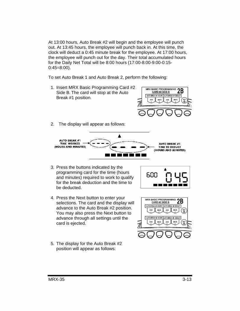
To set Auto Break 1 and Auto Break 2, perform the following:
1. Insert MRX Basic Programming Card #2 Side B. The card will stop at the Auto Break #1 position.
2. The display will appear as follows:
3. Press the buttons indicated by the programming card for the time (hours and minutes) required to work to qualify for the break deduction and the time to be deducted.
4. Press the Next button to enter your selections. The card and the display will advance to the Auto Break #2 position. You may also press the Next button to advance through all settings until the card is ejected.
5. The display for the Auto Break #2 position will appear as follows:
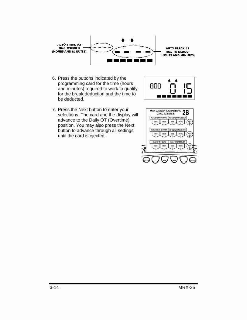
3-14 MRX-35
6. Press the buttons indicated by the programming card for the time (hours and minutes) required to work to qualify for the break deduction and the time to be deducted.
7. Press the Next button to enter your selections. The card and the display will advance to the Daily OT (Overtime) position. You may also press the Next button to advance through all settings until the card is ejected.
MRX-35 3-15
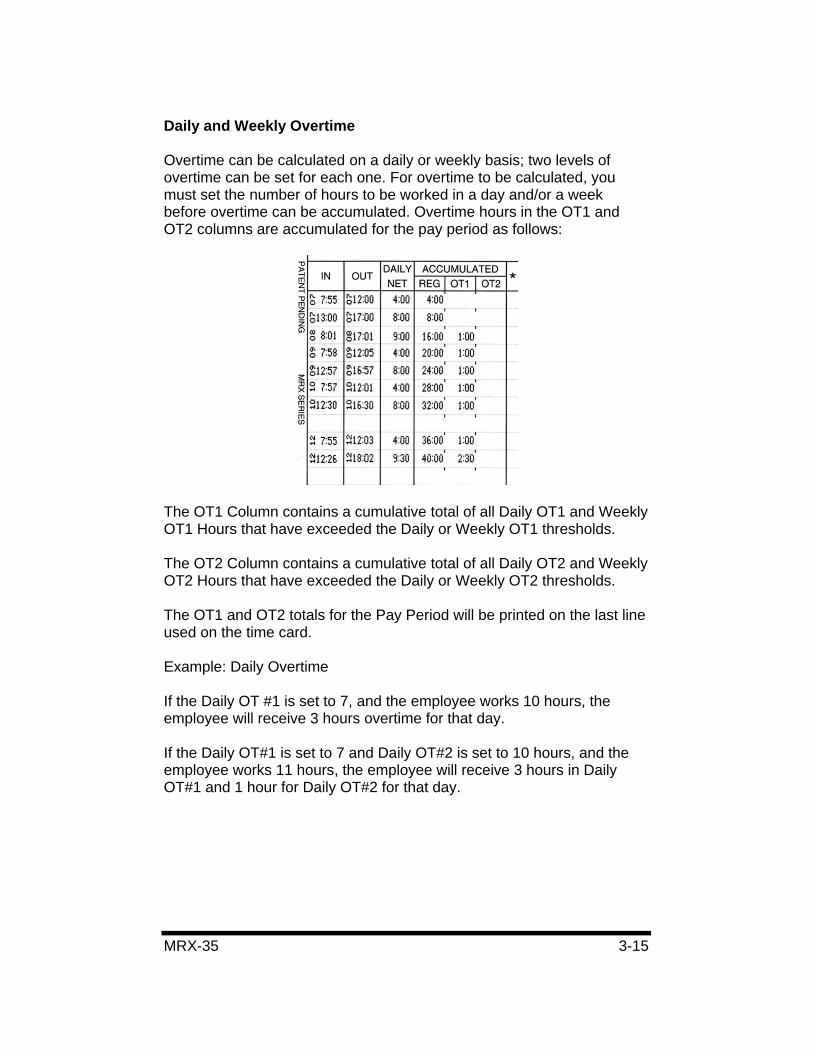
Daily and Weekly Overtime
Overtime can be calculated on a daily or weekly basis; two levels of overtime can be set for each one. For overtime to be calculated, you must set the number of hours to be worked in a day and/or a week before overtime can be accumulated. Overtime hours in the OT1 and OT2 columns are accumulated for the pay period as follows:
The OT1 Column contains a cumulative total of all Daily OT1 and Weekly OT1 Hours that have exceeded the Daily or Weekly OT1 thresholds.
The OT2 Column contains a cumulative total of all Daily OT2 and Weekly OT2 Hours that have exceeded the Daily or Weekly OT2 thresholds.
The OT1 and OT2 totals for the Pay Period will be printed on the last line used on the time card.
Example: Daily Overtime
If the Daily OT #1 is set to 7, and the employee works 10 hours, the employee will receive 3 hours overtime for that day.
If the Daily OT#1 is set to 7 and Daily OT#2 is set to 10 hours, and the employee works 11 hours, the employee will receive 3 hours in Daily OT#1 and 1 hour for Daily OT#2 for that day.
3-16 MRX-35
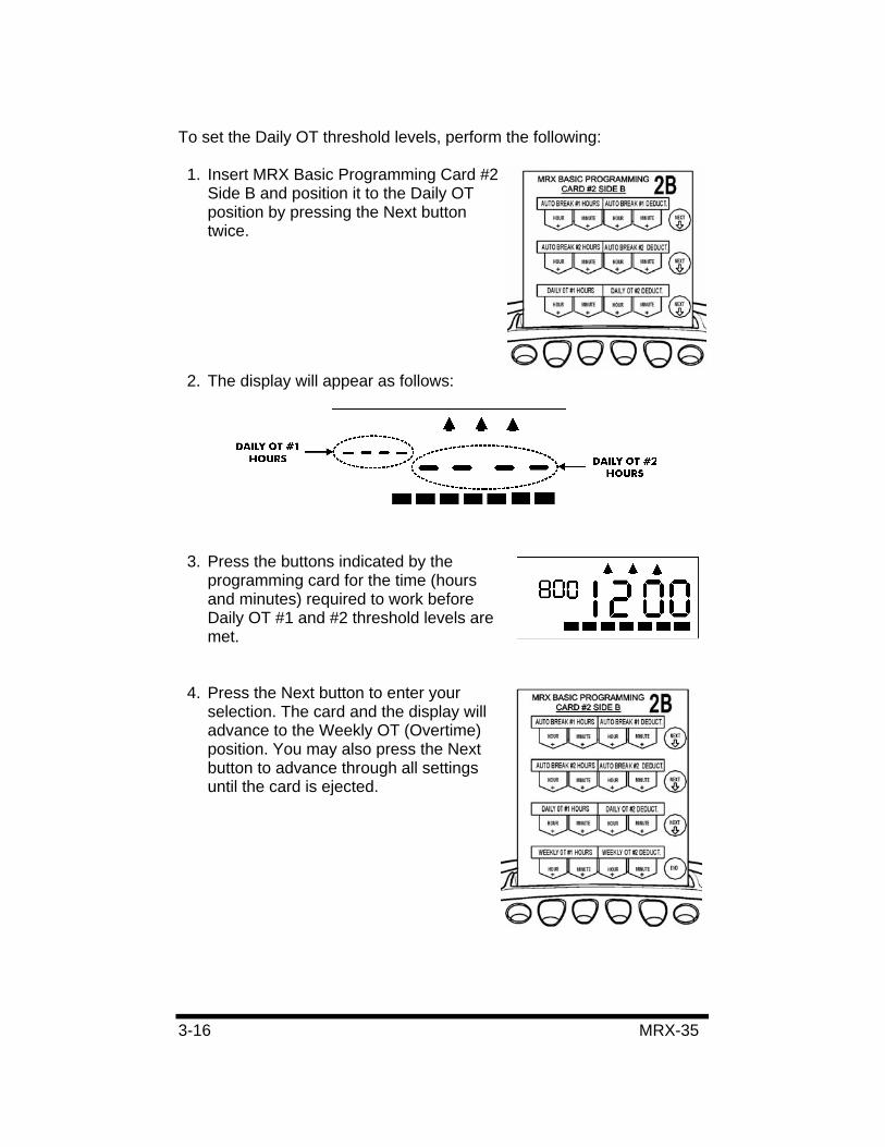
To set the Daily OT threshold levels, perform the following:
1. Insert MRX Basic Programming Card #2 Side B and position it to the Daily OT position by pressing the Next button twice.
2. The display will appear as follows:
3. Press the buttons indicated by the programming card for the time (hours and minutes) required to work before Daily OT #1 and #2 threshold levels are met.
4. Press the Next button to enter your selection. The card and the display will advance to the Weekly OT (Overtime) position. You may also press the Next button to advance through all settings until the card is ejected.
MRX-35 3-17
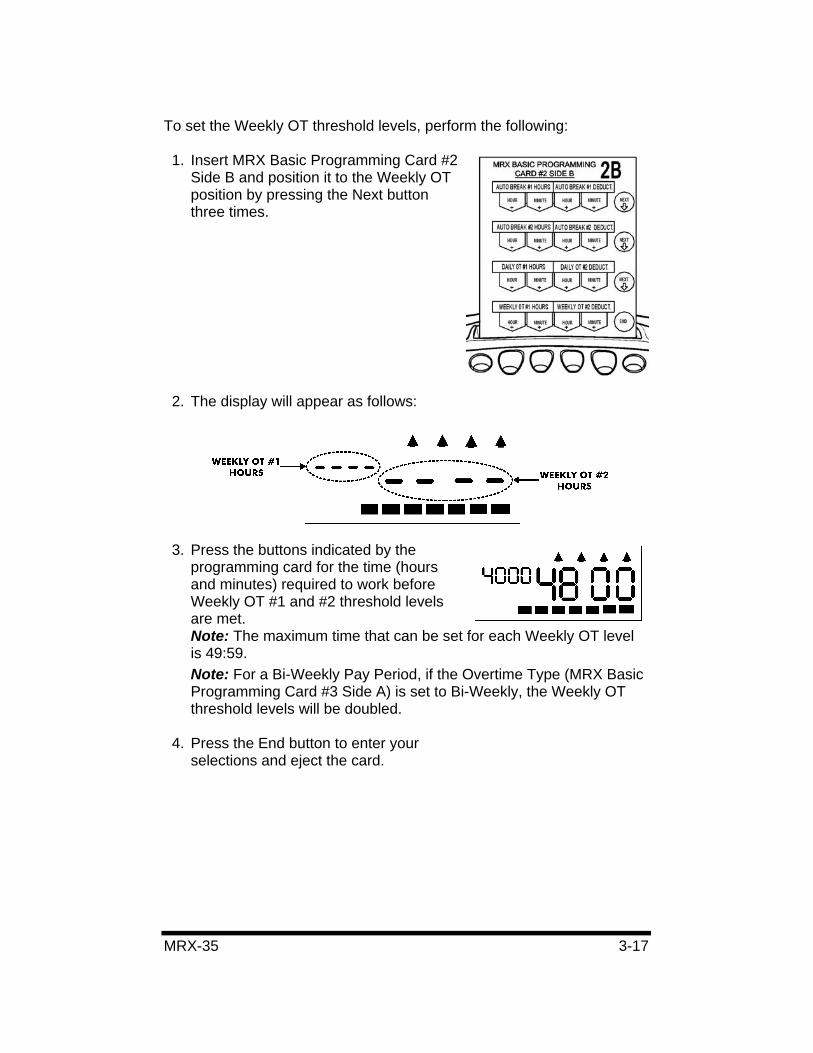
To set the Weekly OT threshold levels, perform the following:
1. Insert MRX Basic Programming Card #2 Side B and position it to the Weekly OT position by pressing the Next button three times.
2. The display will appear as follows:
3. Press the buttons indicated by the programming card for the time (hours and minutes) required to work before Weekly OT #1 and #2 threshold levels are met. Note: The maximum time that can be set for each Weekly OT level is 49:59.Note: For a Bi-Weekly Pay Period, if the Overtime Type (MRX Basic Programming Card #3 Side A) is set to Bi-Weekly, the Weekly OT threshold levels will be doubled.
4. Press the End button to enter your selections and eject the card.
3-18 MRX-35
Imprint and Display Mode
The MRX-35 allows you to select the printing format of the hours on the time card. The hours setting also applies to the hours format in the LCD display. For hours, you can choose either 12-hour (AM/PM, default with PM hours underlined) or a 24-hour (military) format. For the Accumulation Imprint, 1/60th’s (Default) or 1/100th’s of a minute can be selected. The Accumulation Imprint setting only applies to the Daily Net and Accumulated Hours columns on the time card. In and out punch times only print in minutes.
To change these settings, perform the following:
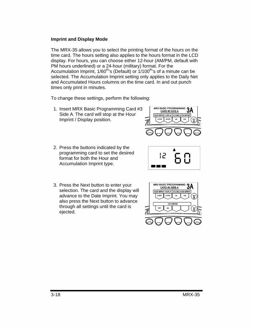
1. Insert MRX Basic Programming Card #3 Side A. The card will stop at the Hour Imprint / Display position.
2. Press the buttons indicated by the programming card to set the desired format for both the Hour and Accumulation Imprint type.
3. Press the Next button to enter your selection. The card and the display will advance to the Date Imprint. You may also press the Next button to advance through all settings until the card is ejected.
MRX-35 3-19
Date Print Mode
In addition to hours and minutes, you can also choose whether to print the day or date on the time card. By default, the Day of Week (MO, TU, WE, etc.) will print out on the time card. You may change this setting to print out a calendar date (DD). If you wish to change the Date Print Mode, perform the following:
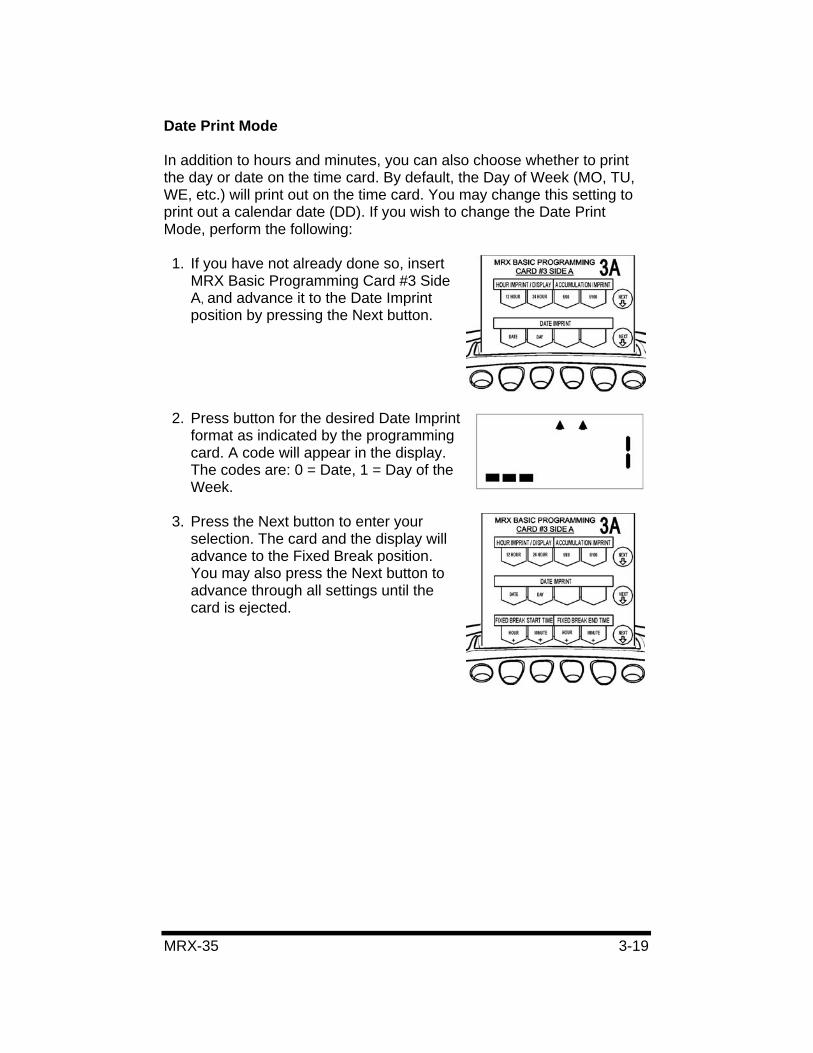
1. If you have not already done so, insert MRX Basic Programming Card #3 Side A, and advance it to the Date Imprint position by pressing the Next button.
2. Press button for the desired Date Imprint format as indicated by the programming card. A code will appear in the display. The codes are: 0 = Date, 1 = Day of the Week.
3. Press the Next button to enter your selection. The card and the display will advance to the Fixed Break position. You may also press the Next button to advance through all settings until the card is ejected.
3-20 MRX-35
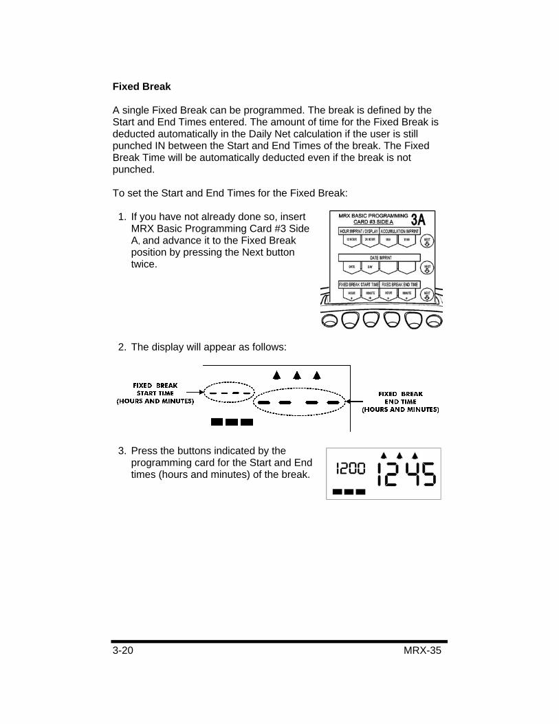
Fixed Break
A single Fixed Break can be programmed. The break is defined by the Start and End Times entered. The amount of time for the Fixed Break is deducted automatically in the Daily Net calculation if the user is still punched IN between the Start and End Times of the break. The Fixed Break Time will be automatically deducted even if the break is not punched.
To set the Start and End Times for the Fixed Break:
1. If you have not already done so, insert MRX Basic Programming Card #3 Side A, and advance it to the Fixed Break position by pressing the Next button twice.
2. The display will appear as follows:
3. Press the buttons indicated by the programming card for the Start and End times (hours and minutes) of the break.
MRX-35 3-21
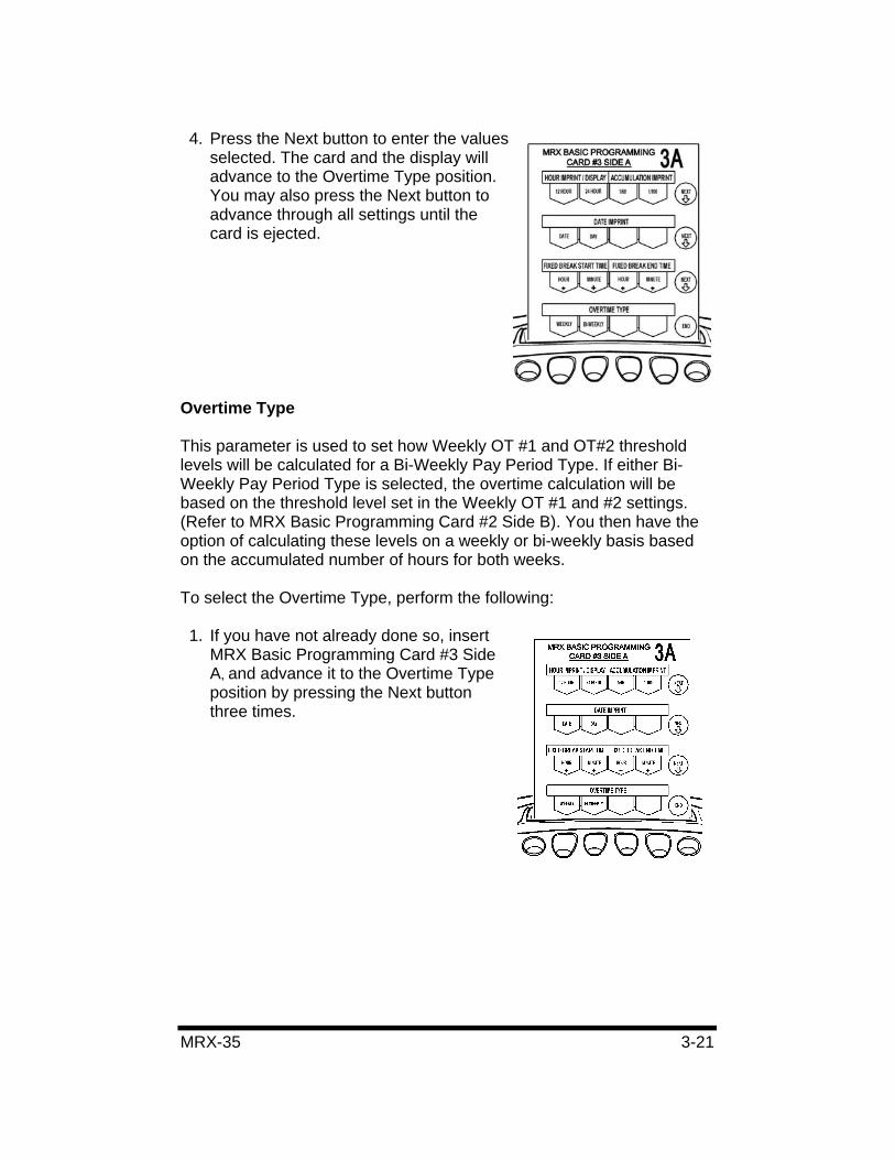
4. Press the Next button to enter the values selected. The card and the display will advance to the Overtime Type position. You may also press the Next button to advance through all settings until the card is ejected.
Overtime Type
This parameter is used to set how Weekly OT #1 and OT#2 threshold levels will be calculated for a Bi-Weekly Pay Period Type. If either Bi-Weekly Pay Period Type is selected, the overtime calculation will be based on the threshold level set in the Weekly OT #1 and #2 settings. (Refer to MRX Basic Programming Card #2 Side B). You then have the option of calculating these levels on a weekly or bi-weekly basis based on the accumulated number of hours for both weeks.
To select the Overtime Type, perform the following:
1. If you have not already done so, insert MRX Basic Programming Card #3 Side A, and advance it to the Overtime Type position by pressing the Next button three times.
3-22 MRX-35
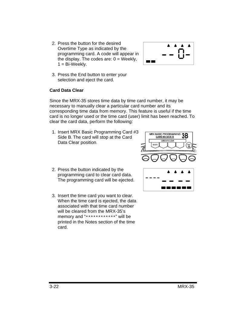
2. Press the button for the desired Overtime Type as indicated by the programming card. A code will appear in the display. The codes are: 0 = Weekly, 1 = Bi-Weekly.
3. Press the End button to enter your selection and eject the card.
Card Data Clear
Since the MRX-35 stores time data by time card number, it may be necessary to manually clear a particular card number and its corresponding time data from memory. This feature is useful if the time card is no longer used or the time card (user) limit has been reached. To clear the card data, perform the following:
1. Insert MRX Basic Programming Card #3 Side B. The card will stop at the Card Data Clear position.
2. Press the button indicated by the programming card to clear card data. The programming card will be ejected.
3. Insert the time card you want to clear. When the time card is ejected, the data associated with that time card number will be cleared from the MRX-35’s memory and “************” will be printed in the Notes section of the time card.
MRX-35 3-23
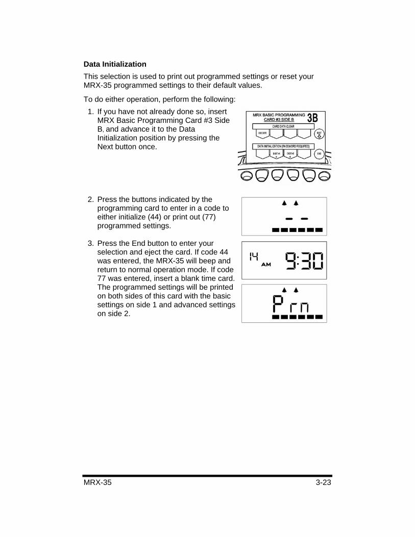
Data Initialization This selection is used to print out programmed settings or reset your MRX-35 programmed settings to their default values.
To do either operation, perform the following: 1. If you have not already done so, insert
MRX Basic Programming Card #3 Side B, and advance it to the Data Initialization position by pressing the Next button once.
2. Press the buttons indicated by the programming card to enter in a code to either initialize (44) or print out (77) programmed settings.
3. Press the End button to enter your selection and eject the card. If code 44 was entered, the MRX-35 will beep and return to normal operation mode. If code 77 was entered, insert a blank time card. The programmed settings will be printed on both sides of this card with the basic settings on side 1 and advanced settings on side 2.
3-24 MRX-35
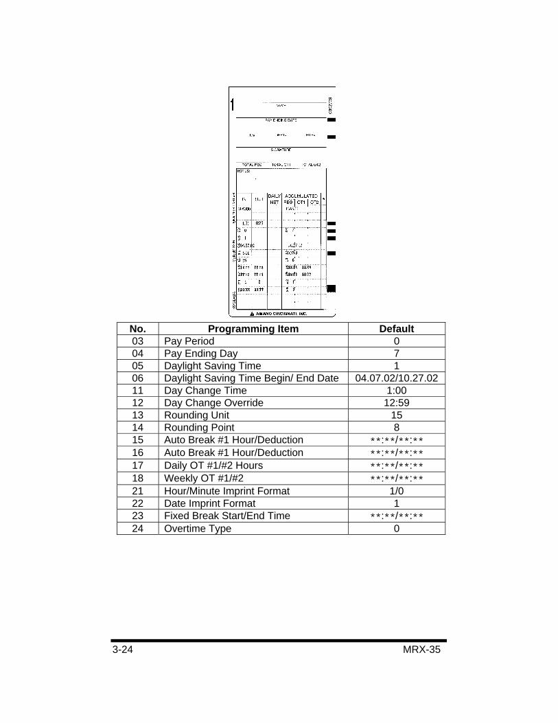
No. Programming Item Default 03 Pay Period 0 04 Pay Ending Day 7 05 Daylight Saving Time 1 06 Daylight Saving Time Begin/ End Date 04.07.02/10.27.02 11 Day Change Time 1:00 12 Day Change Override 12:59 13 Rounding Unit 15 14 Rounding Point 8 15 Auto Break #1 Hour/Deduction **:**/**:**16 Auto Break #1 Hour/Deduction **:**/**:**17 Daily OT #1/#2 Hours **:**/**:**18 Weekly OT #1/#2 **:**/**:**21 Hour/Minute Imprint Format 1/0 22 Date Imprint Format 1 23 Fixed Break Start/End Time **:**/**:**24 Overtime Type 0
MRX-35 3-25
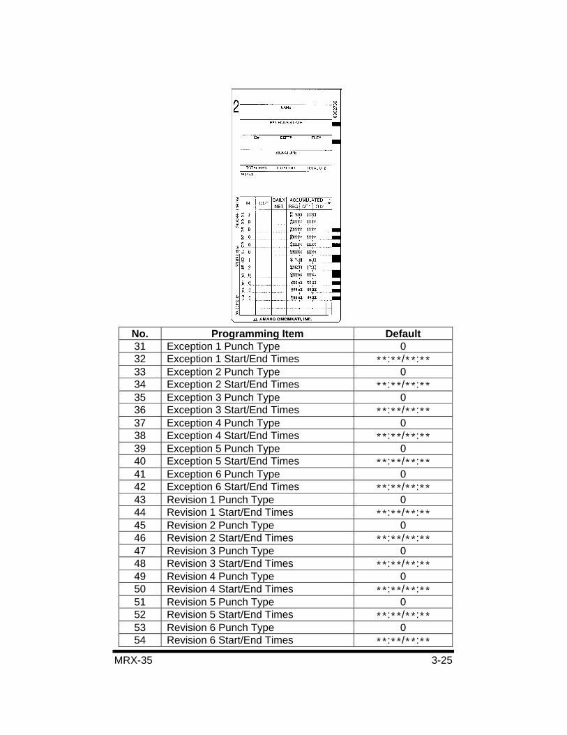
No. Programming Item Default 31 Exception 1 Punch Type 0 32 Exception 1 Start/End Times **:**/**:**33 Exception 2 Punch Type 0 34 Exception 2 Start/End Times **:**/**:**35 Exception 3 Punch Type 0 36 Exception 3 Start/End Times **:**/**:**37 Exception 4 Punch Type 0 38 Exception 4 Start/End Times **:**/**:**39 Exception 5 Punch Type 0 40 Exception 5 Start/End Times **:**/**:**41 Exception 6 Punch Type 0 42 Exception 6 Start/End Times **:**/**:**43 Revision 1 Punch Type 0 44 Revision 1 Start/End Times **:**/**:**45 Revision 2 Punch Type 0 46 Revision 2 Start/End Times **:**/**:**47 Revision 3 Punch Type 0 48 Revision 3 Start/End Times **:**/**:**49 Revision 4 Punch Type 0 50 Revision 4 Start/End Times **:**/**:**51 Revision 5 Punch Type 0 52 Revision 5 Start/End Times **:**/**:**53 Revision 6 Punch Type 0 54 Revision 6 Start/End Times **:**/**:**
3-26 MRX-35
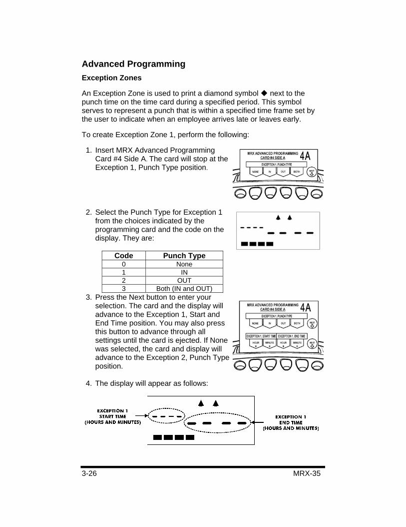
Advanced Programming Exception Zones
An Exception Zone is used to print a diamond symbol next to the punch time on the time card during a specified period. This symbol serves to represent a punch that is within a specified time frame set by the user to indicate when an employee arrives late or leaves early.
To create Exception Zone 1, perform the following:
1. Insert MRX Advanced Programming Card #4 Side A. The card will stop at the Exception 1, Punch Type position.
2. Select the Punch Type for Exception 1 from the choices indicated by the programming card and the code on the display. They are:
Code Punch Type 0 None 1 IN 2 OUT 3 Both (IN and OUT)
3. Press the Next button to enter your selection. The card and the display will advance to the Exception 1, Start and End Time position. You may also press this button to advance through all settings until the card is ejected. If None was selected, the card and display will advance to the Exception 2, Punch Type position.
4. The display will appear as follows:
MRX-35 3-27
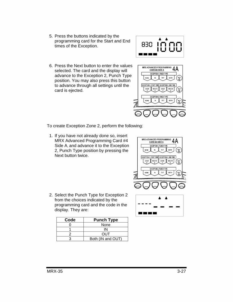
5. Press the buttons indicated by the programming card for the Start and End times of the Exception.
6. Press the Next button to enter the values selected. The card and the display will advance to the Exception 2, Punch Type position. You may also press this button to advance through all settings until the card is ejected.
To create Exception Zone 2, perform the following:
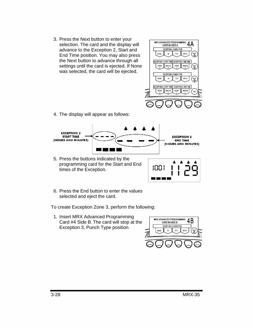
1. If you have not already done so, insert MRX Advanced Programming Card #4 Side A, and advance it to the Exception 2, Punch Type position by pressing the Next button twice.
2. Select the Punch Type for Exception 2 from the choices indicated by the programming card and the code in the display. They are:
Code Punch Type 0 None 1 IN 2 OUT 3 Both (IN and OUT)
3-28 MRX-35
3. Press the Next button to enter your selection. The card and the display will advance to the Exception 2, Start and End Time position. You may also press the Next button to advance through all settings until the card is ejected. If None was selected, the card will be ejected.
4. The display will appear as follows:
5. Press the buttons indicated by the programming card for the Start and End times of the Exception.
6. Press the End button to enter the values selected and eject the card.
To create Exception Zone 3, perform the following:
1. Insert MRX Advanced Programming Card #4 Side B. The card will stop at the Exception 3, Punch Type position.
MRX-35 3-29
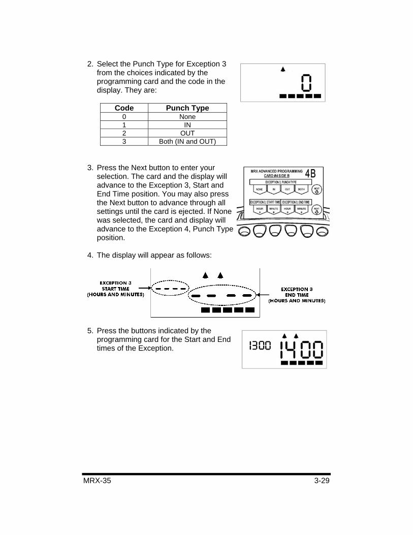
2. Select the Punch Type for Exception 3 from the choices indicated by the programming card and the code in the display. They are:
Code Punch Type 0 None 1 IN 2 OUT 3 Both (IN and OUT)
3. Press the Next button to enter your selection. The card and the display will advance to the Exception 3, Start and End Time position. You may also press the Next button to advance through all settings until the card is ejected. If None was selected, the card and display will advance to the Exception 4, Punch Type position.
4. The display will appear as follows:
5. Press the buttons indicated by the programming card for the Start and End times of the Exception.
3-30 MRX-35
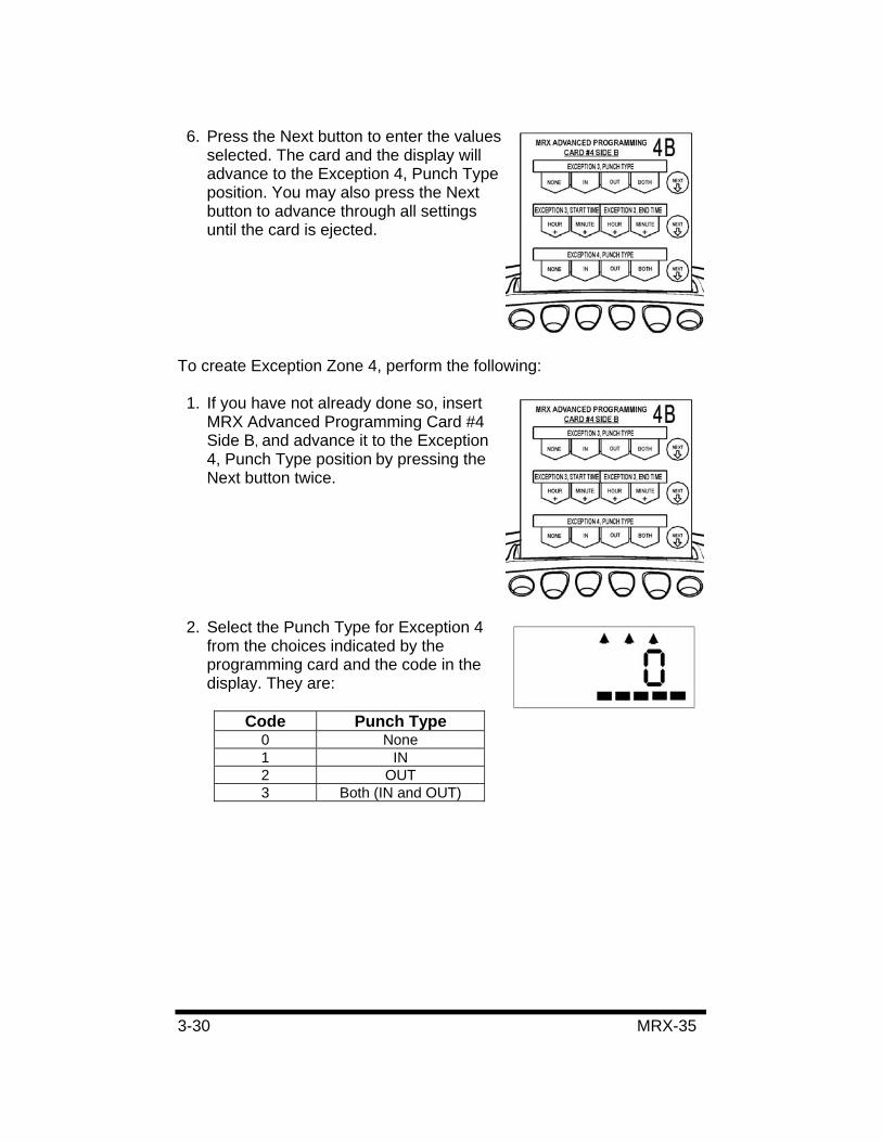
6. Press the Next button to enter the values selected. The card and the display will advance to the Exception 4, Punch Type position. You may also press the Next button to advance through all settings until the card is ejected.
To create Exception Zone 4, perform the following:
1. If you have not already done so, insert MRX Advanced Programming Card #4 Side B, and advance it to the Exception 4, Punch Type position by pressing the Next button twice.
2. Select the Punch Type for Exception 4 from the choices indicated by the programming card and the code in the display. They are:
Code Punch Type 0 None 1 IN 2 OUT 3 Both (IN and OUT)
MRX-35 3-31
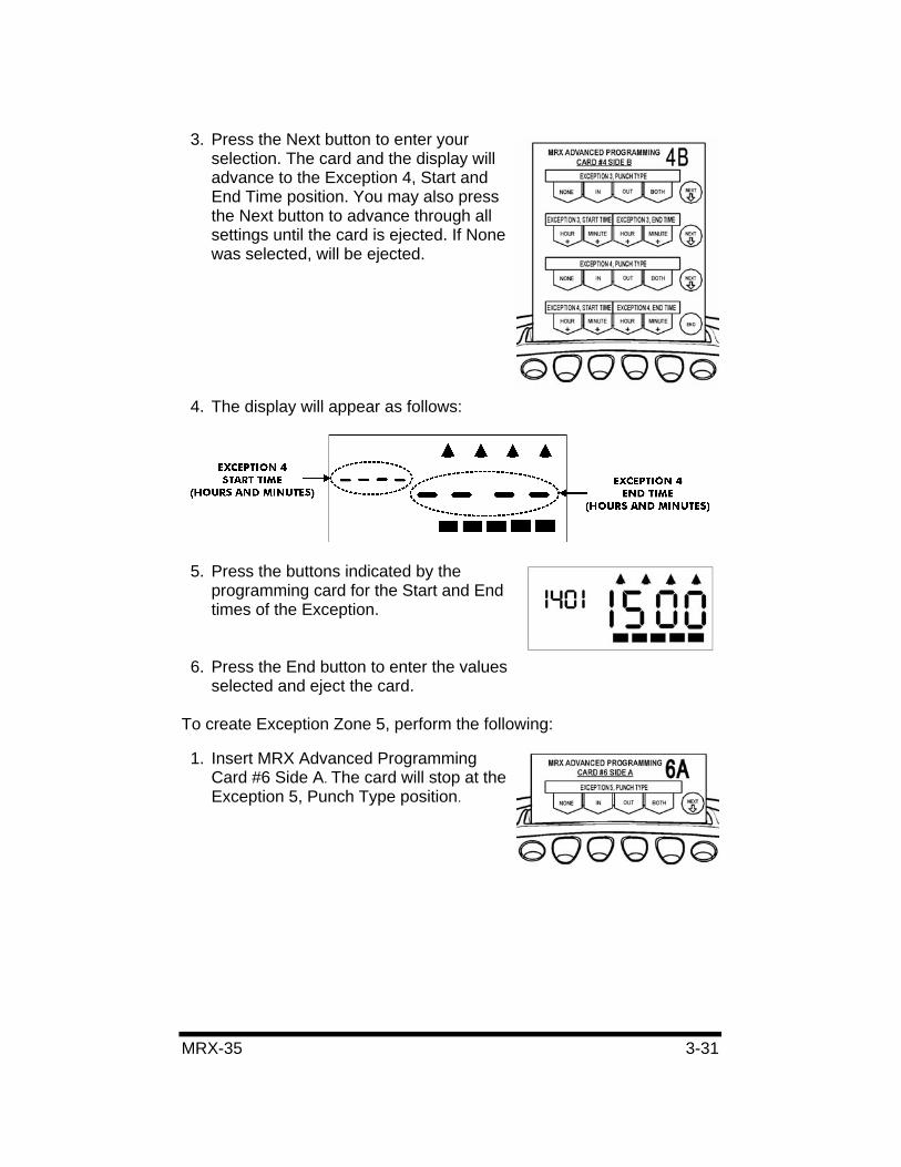
3. Press the Next button to enter your selection. The card and the display will advance to the Exception 4, Start and End Time position. You may also press the Next button to advance through all settings until the card is ejected. If None was selected, will be ejected.
4. The display will appear as follows:
5. Press the buttons indicated by the programming card for the Start and End times of the Exception.
6. Press the End button to enter the values selected and eject the card.
To create Exception Zone 5, perform the following:
1. Insert MRX Advanced Programming Card #6 Side A. The card will stop at the Exception 5, Punch Type position.
3-32 MRX-35
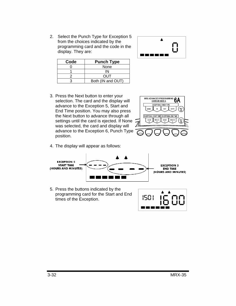
2. Select the Punch Type for Exception 5 from the choices indicated by the programming card and the code in the display. They are:
Code Punch Type 0 None 1 IN 2 OUT 3 Both (IN and OUT)
3. Press the Next button to enter your selection. The card and the display will advance to the Exception 5, Start and End Time position. You may also press the Next button to advance through all settings until the card is ejected. If None was selected, the card and display will advance to the Exception 6, Punch Type position.
4. The display will appear as follows:
5. Press the buttons indicated by the programming card for the Start and End times of the Exception.
MRX-35 3-33
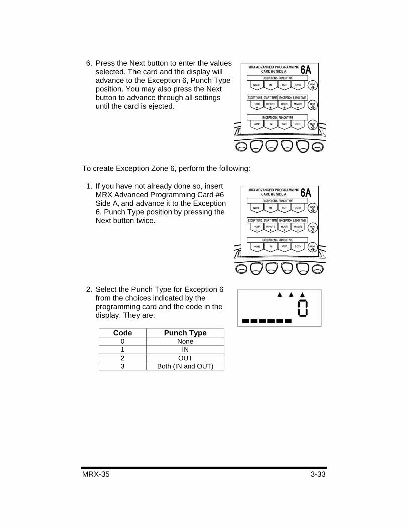
6. Press the Next button to enter the values selected. The card and the display will advance to the Exception 6, Punch Type position. You may also press the Next button to advance through all settings until the card is ejected.
To create Exception Zone 6, perform the following:
1. If you have not already done so, insert MRX Advanced Programming Card #6 Side A, and advance it to the Exception 6, Punch Type position by pressing the Next button twice.
2. Select the Punch Type for Exception 6 from the choices indicated by the programming card and the code in the display. They are:
Code Punch Type 0 None 1 IN 2 OUT 3 Both (IN and OUT)
3-34 MRX-35
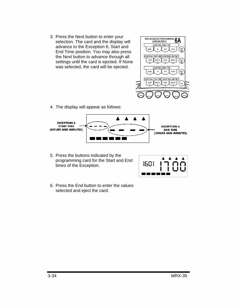
3. Press the Next button to enter your selection. The card and the display will advance to the Exception 6, Start and End Time position. You may also press the Next button to advance through all settings until the card is ejected. If None was selected, the card will be ejected.
4. The display will appear as follows:
5. Press the buttons indicated by the programming card for the Start and End times of the Exception.
6. Press the End button to enter the values selected and eject the card.
MRX-35 3-35
Revision Zones
A Revision Zone is a window of time in which the employee may punch in or out (not both), but the MRX-35 will not begin or end calculation at the moment of punch. A punch time in a Revision Zone will be “revised” to a pre-configured time. A Revision Zone consists of a Punch Type, Start Time, and End Time. If the Punch Type is set to IN, then the actual punch time within the Revision Zone will be revised to the Revision Zone End Time. If the Punch Type is set to OUT, then the actual punch time within the Revision Zone will be revised to the Revision Zone Start Time.
When a Revision Zone is enabled, the MRX-35 considers “revised” punch times to be the official IN or OUT punches. This feature will prevent employees from accumulating extra time by punching in early or punching out late. Up to (6) Revision Zones can be created.
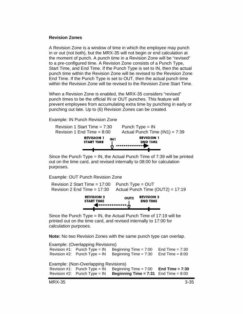
Example: IN Punch Revision Zone Revision 1 Start Time = 7:30 Punch Type = IN Revision 1 End Time = 8:00 Actual Punch Time (IN1) = 7:39
Since the Punch Type = IN, the Actual Punch Time of 7:39 will be printed out on the time card, and revised internally to 08:00 for calculation purposes.
Example: OUT Punch Revision Zone Revision 2 Start Time = 17:00 Punch Type = OUT Revision 2 End Time = 17:30 Actual Punch Time (OUT2) = 17:19
Since the Punch Type = IN, the Actual Punch Time of 17:19 will be printed out on the time card, and revised internally to 17:00 for calculation purposes.
Note: No two Revision Zones with the same punch type can overlap.
Example: (Overlapping Revisions) Revision #1: Punch Type = IN Beginning Time = 7:00 End Time = 7:30 Revision #2: Punch Type = IN Beginning Time = 7:30 End Time = 8:00
Example: (Non-Overlapping Revisions) Revision #1: Punch Type = IN Beginning Time = 7:00 End Time = 7:30 Revision #2: Punch Type = IN Beginning Time = 7:31 End Time = 8:00
3-36 MRX-35
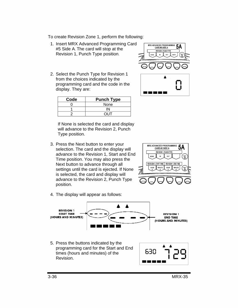
To create Revision Zone 1, perform the following: 1. Insert MRX Advanced Programming Card
#5 Side A. The card will stop at the Revision 1, Punch Type position.
2. Select the Punch Type for Revision 1 from the choices indicated by the programming card and the code in the display. They are:
Code Punch Type 0 None 1 IN 2 OUT
If None is selected the card and display will advance to the Revision 2, Punch Type position.
3. Press the Next button to enter your selection. The card and the display will advance to the Revision 1, Start and End Time position. You may also press the Next button to advance through all settings until the card is ejected. If None is selected, the card and display will advance to the Revision 2, Punch Type position.
4. The display will appear as follows:
5. Press the buttons indicated by the programming card for the Start and End times (hours and minutes) of the Revision.
MRX-35 3-37
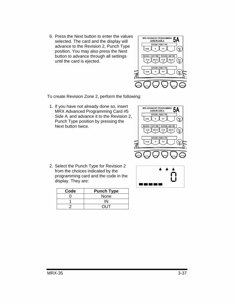
6. Press the Next button to enter the values selected. The card and the display will advance to the Revision 2, Punch Type position. You may also press the Next button to advance through all settings until the card is ejected.
To create Revision Zone 2, perform the following:
1. If you have not already done so, insert MRX Advanced Programming Card #5 Side A, and advance it to the Revision 2, Punch Type position by pressing the Next button twice.
2. Select the Punch Type for Revision 2 from the choices indicated by the programming card and the code in the display. They are:
Code Punch Type 0 None 1 IN 2 OUT
3-38 MRX-35
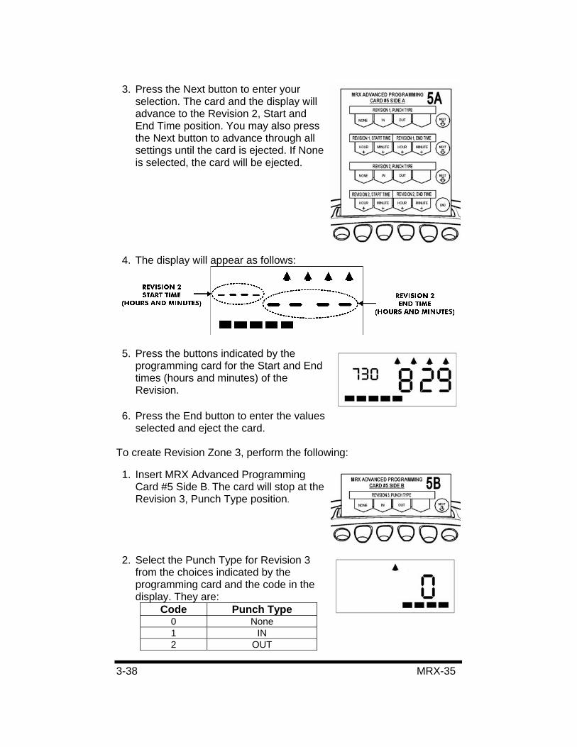
3. Press the Next button to enter your selection. The card and the display will advance to the Revision 2, Start and End Time position. You may also press the Next button to advance through all settings until the card is ejected. If None is selected, the card will be ejected.
4. The display will appear as follows:
5. Press the buttons indicated by the programming card for the Start and End times (hours and minutes) of the Revision.
6. Press the End button to enter the values selected and eject the card.
To create Revision Zone 3, perform the following:
1. Insert MRX Advanced Programming Card #5 Side B. The card will stop at the Revision 3, Punch Type position.
2. Select the Punch Type for Revision 3 from the choices indicated by the programming card and the code in the display. They are:
Code Punch Type 0 None 1 IN 2 OUT
MRX-35 3-39
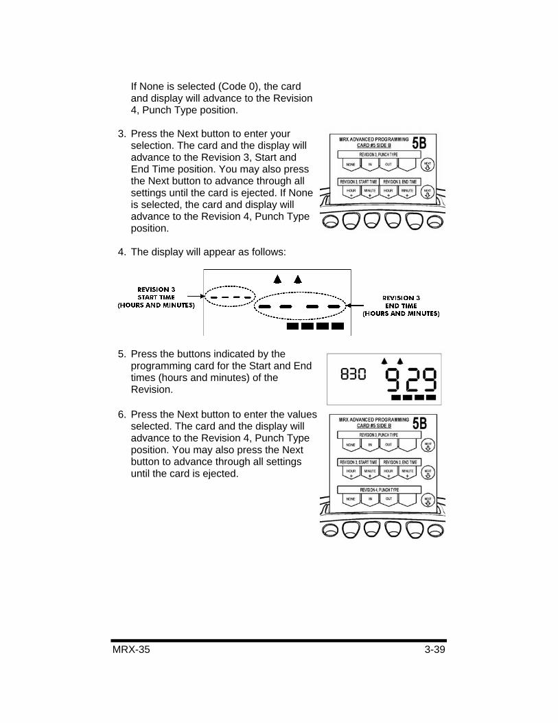
If None is selected (Code 0), the card and display will advance to the Revision 4, Punch Type position.
3. Press the Next button to enter your selection. The card and the display will advance to the Revision 3, Start and End Time position. You may also press the Next button to advance through all settings until the card is ejected. If None is selected, the card and display will advance to the Revision 4, Punch Type position.
4. The display will appear as follows:
5. Press the buttons indicated by the programming card for the Start and End times (hours and minutes) of the Revision.
6. Press the Next button to enter the values selected. The card and the display will advance to the Revision 4, Punch Type position. You may also press the Next button to advance through all settings until the card is ejected.
3-40 MRX-35
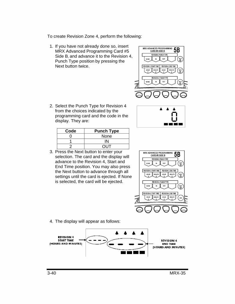
To create Revision Zone 4, perform the following:
1. If you have not already done so, insert MRX Advanced Programming Card #5 Side B, and advance it to the Revision 4, Punch Type position by pressing the Next button twice.
2. Select the Punch Type for Revision 4 from the choices indicated by the programming card and the code in the display. They are:
Code Punch Type 0 None 1 IN 2 OUT
3. Press the Next button to enter your selection. The card and the display will advance to the Revision 4, Start and End Time position. You may also press the Next button to advance through all settings until the card is ejected. If None is selected, the card will be ejected.
4. The display will appear as follows:
MRX-35 3-41
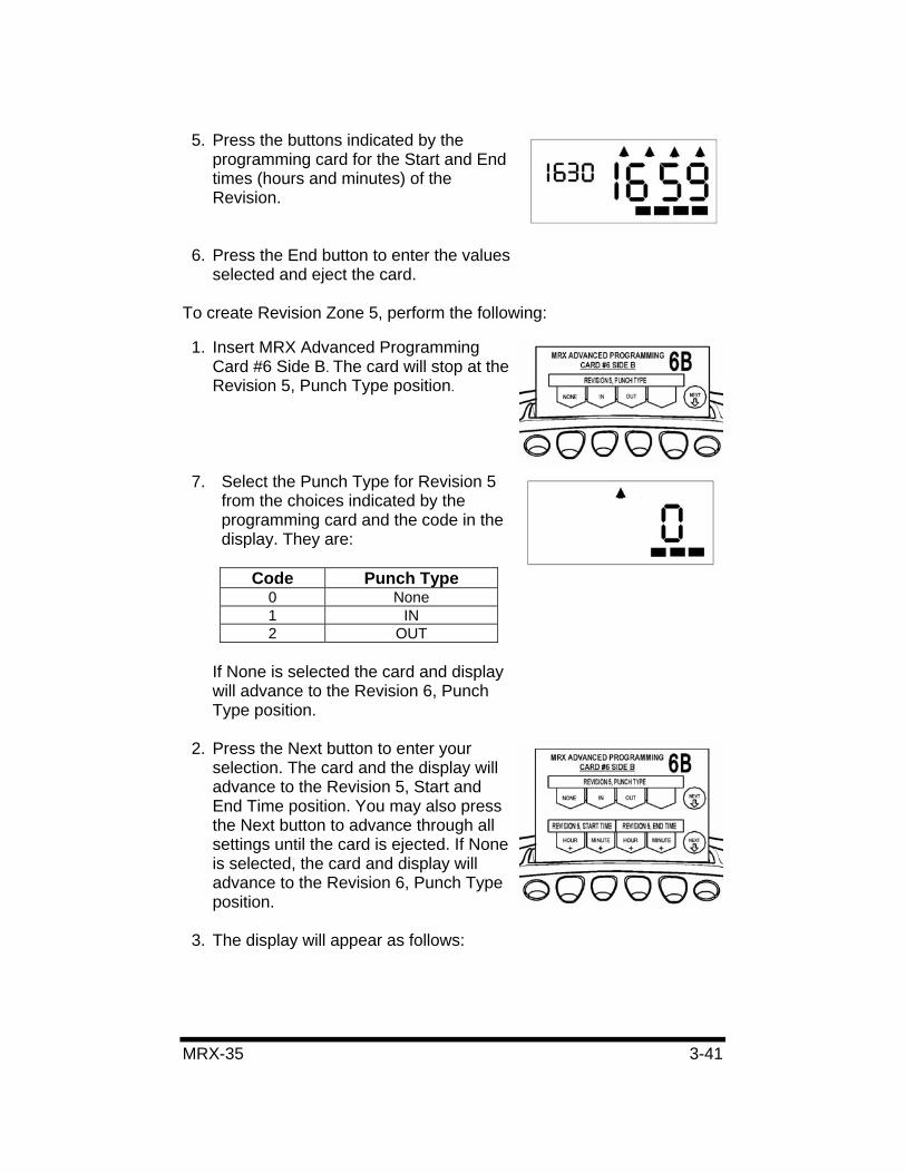
5. Press the buttons indicated by the programming card for the Start and End times (hours and minutes) of the Revision.
6. Press the End button to enter the values selected and eject the card.
To create Revision Zone 5, perform the following:
1. Insert MRX Advanced Programming Card #6 Side B. The card will stop at the Revision 5, Punch Type position.
7. Select the Punch Type for Revision 5 from the choices indicated by the programming card and the code in the display. They are:
Code Punch Type 0 None 1 IN 2 OUT
If None is selected the card and display will advance to the Revision 6, Punch Type position.
2. Press the Next button to enter your selection. The card and the display will advance to the Revision 5, Start and End Time position. You may also press the Next button to advance through all settings until the card is ejected. If None is selected, the card and display will advance to the Revision 6, Punch Type position.
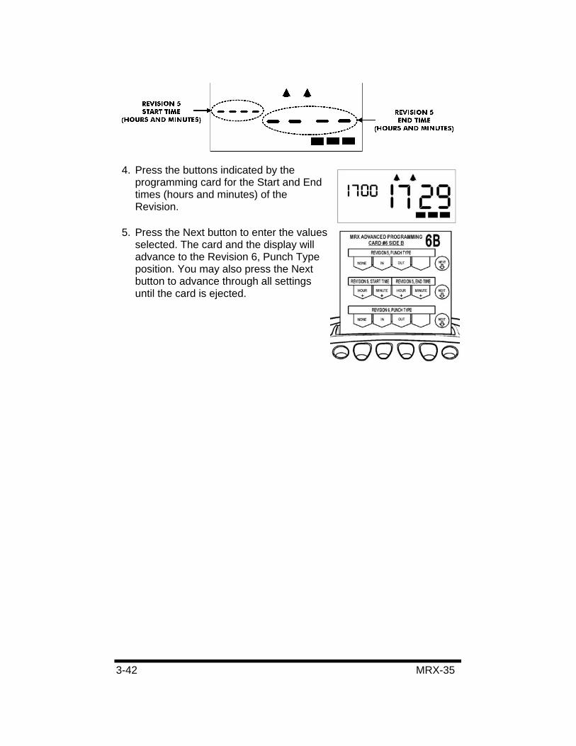
3. The display will appear as follows:
3-42 MRX-35
4. Press the buttons indicated by the programming card for the Start and End times (hours and minutes) of the Revision.
5. Press the Next button to enter the values selected. The card and the display will advance to the Revision 6, Punch Type position. You may also press the Next button to advance through all settings until the card is ejected.
MRX-35 3-43
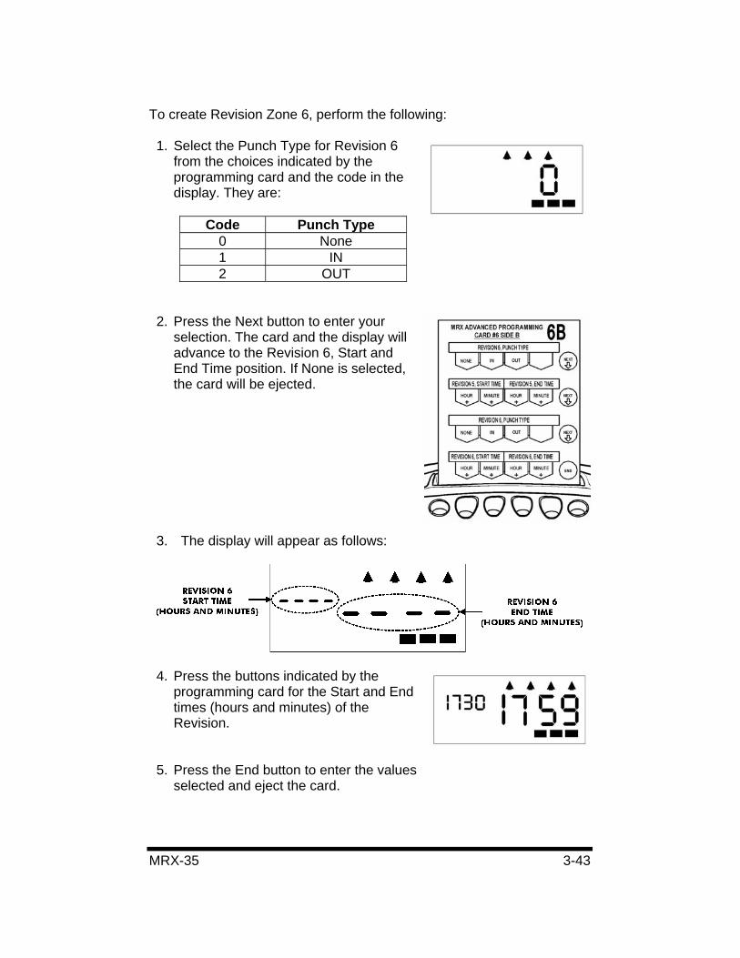
To create Revision Zone 6, perform the following:
1. Select the Punch Type for Revision 6 from the choices indicated by the programming card and the code in the display. They are:
Code Punch Type 0 None 1 IN 2 OUT
2. Press the Next button to enter your selection. The card and the display will advance to the Revision 6, Start and End Time position. If None is selected, the card will be ejected.
3. The display will appear as follows:
4. Press the buttons indicated by the programming card for the Start and End times (hours and minutes) of the Revision.
5. Press the End button to enter the values selected and eject the card.

3-44 MRX-35
MRX-35 4-1
Chapter 4: Maintenance and Troubleshooting
Cleaning (Exterior)
WARNING!:• Unplug the unit before attempting to clean it. • Do not touch the plug with wet hands. • Always hold the plug when removing it from the power
receptacle. • Wiping the case with volatile chemicals such as benzene
or thinner will cause it to become deformed and discolored.
The case can be cleaned by gently wiping it with a soft cloth moistened with either water or a neutral cleanser.
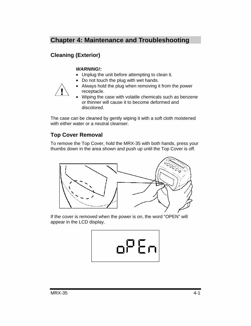
Top Cover Removal To remove the Top Cover, hold the MRX-35 with both hands, press your thumbs down in the area shown and push up until the Top Cover is off.
If the cover is removed when the power is on, the word “OPEN” will appear in the LCD display.
4-2 MRX-35
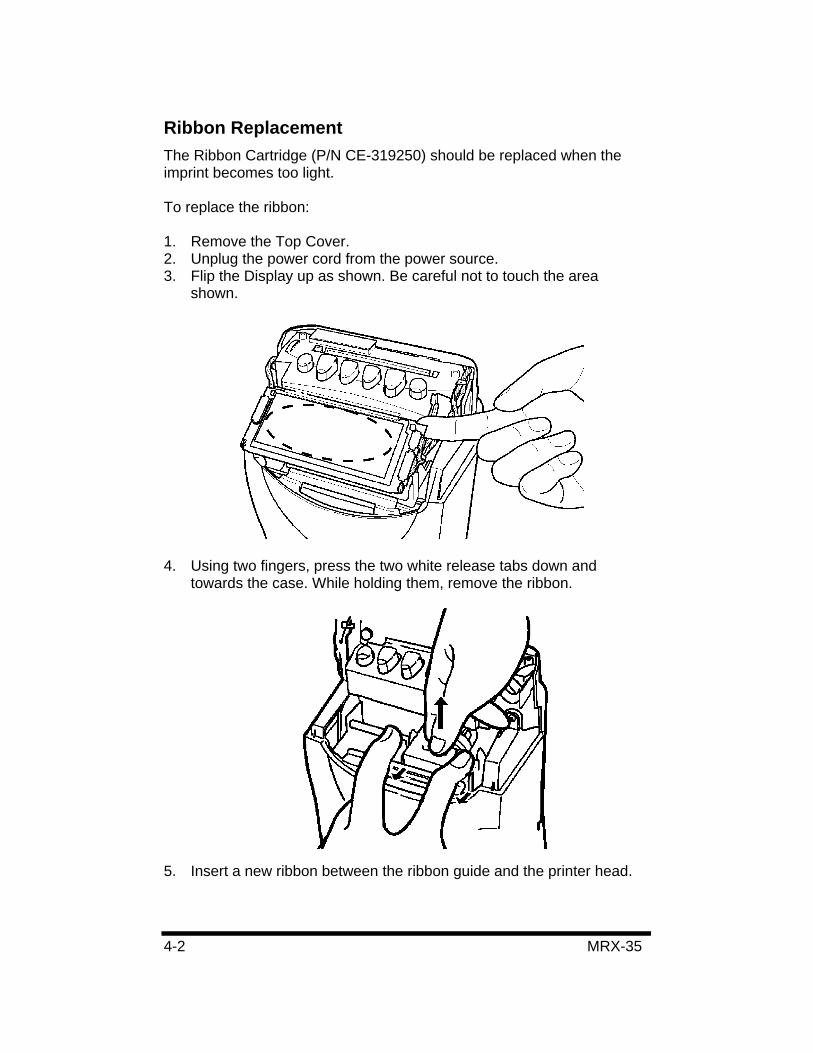
Ribbon Replacement The Ribbon Cartridge (P/N CE-319250) should be replaced when the imprint becomes too light.
To replace the ribbon:
1. Remove the Top Cover. 2. Unplug the power cord from the power source. 3. Flip the Display up as shown. Be careful not to touch the area
shown.
4. Using two fingers, press the two white release tabs down and towards the case. While holding them, remove the ribbon.
5. Insert a new ribbon between the ribbon guide and the printer head.
MRX-35 4-3
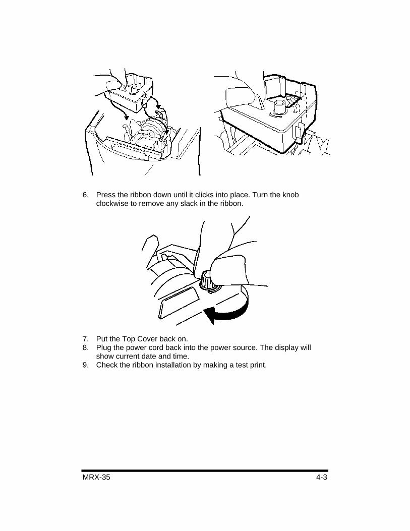
6. Press the ribbon down until it clicks into place. Turn the knob clockwise to remove any slack in the ribbon.
7. Put the Top Cover back on. 8. Plug the power cord back into the power source. The display will
show current date and time. 9. Check the ribbon installation by making a test print.
4-4 MRX-35
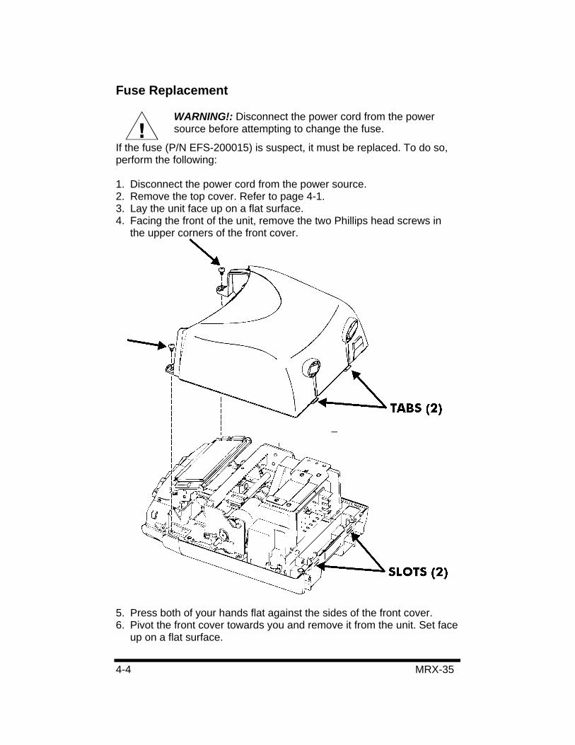
Fuse Replacement
WARNING!: Disconnect the power cord from the power source before attempting to change the fuse.
If the fuse (P/N EFS-200015) is suspect, it must be replaced. To do so, perform the following:
1. Disconnect the power cord from the power source. 2. Remove the top cover. Refer to page 4-1. 3. Lay the unit face up on a flat surface. 4. Facing the front of the unit, remove the two Phillips head screws in
the upper corners of the front cover.
5. Press both of your hands flat against the sides of the front cover. 6. Pivot the front cover towards you and remove it from the unit. Set face
up on a flat surface.

MRX-35 4-5
7. Locate the fuse. Replace the desired fuse only with one of the same type and rating.
8. With the front cover on a flat surface and facing up, press both of your hands flat against the sides.
9. Facing the bottom of the unit, set and align the tabs on the bottom of the front cover with the slots on the housing.
10. Pivot the front cover towards the housing, push it down in place, and then secure it with the two Phillips head screws.
11. Re-install the Top Cover. 12. If necessary, reconnect the power cord to the power source.
Troubleshooting
Problem Possible Cause Solution
Card will not feed into unit.
• Power failure. • Power connection is
loose.
• Wait until power is restored.
• Check connection. Card ejected without printing.
Card inserted upside down or on wrong side.
Turn card around and try again.
Gaining/Losing time. Time Setting is wrong. Re-enter the Time Settings.
Wrong Date Date Setting is wrong. Re-enter the Date Settings.
Light Imprint Ribbon cartridge is worn. Replace ribbon cartridge.
Misprinting Ribbon cartridge is not in right place. Place it in right position.
Error code See Error Code Charts
4-6 MRX-35
Error Codes The table below lists the possible Error Codes that may appear in the display and their causes.
Figure 4-1 Error Code Message
Error Code Description Possible Cause and Solution
E-00 EEPROM Error Internal error. Contact your local Amano service dealer or representative.
E-01 Card Error Wrong side of card inserted. Verify Pay Period and the correct side.
E-02 Home Position
E-03 Dot Pulse
E-04 Timing Pulse
E-05 Row Position
E-06 Gain Sensor
Internal printer error. Contact your local Amano service dealer or representative.
E-07 Start Mark
E-08 Check Code
E-09 Stop Mark
Verify that right (Barcode) margin of card is free of dust, dirt, or marks. Insert new time card. If error persists, contact your local Amano service dealer or representative.
E-12 Invalid Card Incorrect card type was inserted. E-13 Read Error Card removed before it is processed. E-14 Feed Error Card fed into card throat incorrectly.
E-15 4-Punch Card already has 4-punch daily maximum.
E-17 Previous Punch Time card for printing is earlier than previous punch.
E-21 No Card Data No data for card inserted (after card was cleared from memory).
E-22 No Clock Data No internal clock data.
E-23 Duplicate Data There are two sets of data for the same time card number. Clear card data.
E-30 Card Row Number of lines to print exceeds card row specification.
MRX-35 4-7
Error Code Description Possible Cause and Solution
E-96 CPU Error Internal error. Contact your local Amano service dealer or representative.
E-98 Password Incorrect password entered.
Parameter Error Codes The table below lists the possible Parameter Error Codes that may appear in the display when a parameter is incorrectly set.
Figure 4-2 Parameter Error Code Message
Error Code Programming Card DescriptionP-01 Time Settings P-02 Date Settings P-03 Pay Period Type P-04
Basic Programming Card #1 Side A
Pay Period End Day P-05 Daylight Saving Time P-06 Daylight Saving Time Begin Date P-07
Basic Programming Card #1 Side B
Daylight Saving Time End Date P-11 Day Change Time P-12 Day Change Override Time P-13 Rounding Unit P-14
Basic Programming Card #2 Side A
Rounding Point P-15 Auto Break #1 P-16 Auto Break #2 P-17 Daily OT#1/#2 P-18
Basic Programming Card #2 Side B
Weekly OT#1/#2 P-21 Hour/Minute Imprint Format P-22 Date Imprint Format P-23 Fixed Break Start/End Time P-24
Basic Programming Card #3 Side A
Overtime Type P-25 Card Data Clear P-26
Basic Programming Card #3 Side B Data Initialization
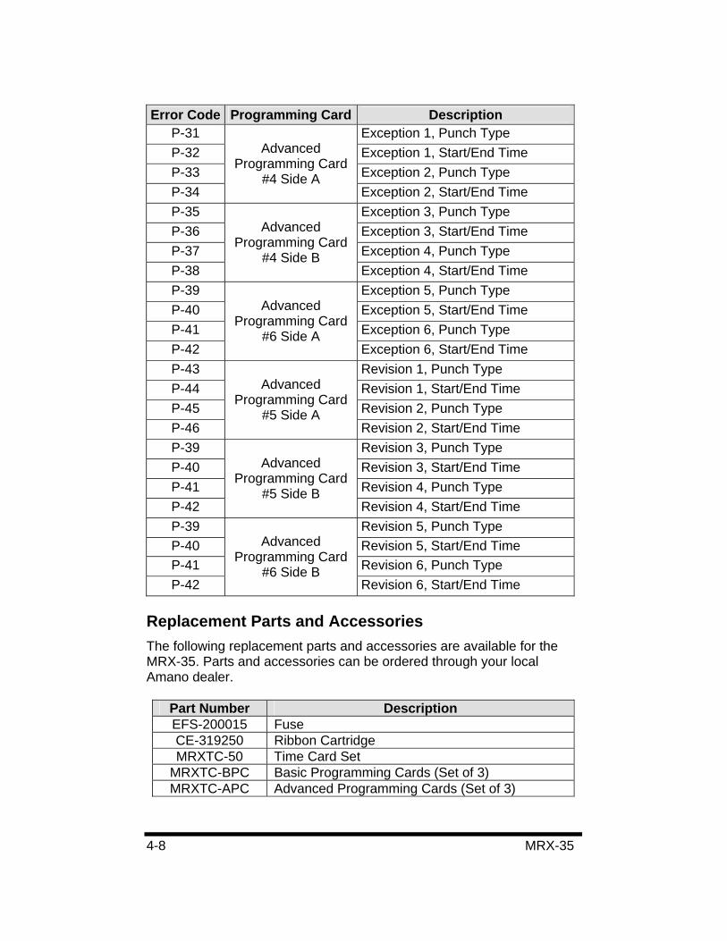
4-8 MRX-35
Error Code Programming Card DescriptionP-31 Exception 1, Punch Type P-32 Exception 1, Start/End Time P-33 Exception 2, Punch Type P-34
Advanced Programming Card
#4 Side A Exception 2, Start/End Time
P-35 Exception 3, Punch Type P-36 Exception 3, Start/End Time P-37 Exception 4, Punch Type P-38
Advanced Programming Card
#4 Side B Exception 4, Start/End Time
P-39 Exception 5, Punch Type P-40 Exception 5, Start/End Time P-41 Exception 6, Punch Type P-42
Advanced Programming Card
#6 Side A Exception 6, Start/End Time
P-43 Revision 1, Punch Type P-44 Revision 1, Start/End Time P-45 Revision 2, Punch Type P-46
Advanced Programming Card
#5 Side A Revision 2, Start/End Time
P-39 Revision 3, Punch Type P-40 Revision 3, Start/End Time P-41 Revision 4, Punch Type P-42
Advanced Programming Card
#5 Side B Revision 4, Start/End Time
P-39 Revision 5, Punch Type P-40 Revision 5, Start/End Time P-41 Revision 6, Punch Type P-42
Advanced Programming Card
#6 Side B Revision 6, Start/End Time
Replacement Parts and Accessories The following replacement parts and accessories are available for the MRX-35. Parts and accessories can be ordered through your local Amano dealer.
Part Number Description EFS-200015 Fuse CE-319250 Ribbon Cartridge MRXTC-50 Time Card Set
MRXTC-BPC Basic Programming Cards (Set of 3) MRXTC-APC Advanced Programming Cards (Set of 3)
MRX-35 4-9
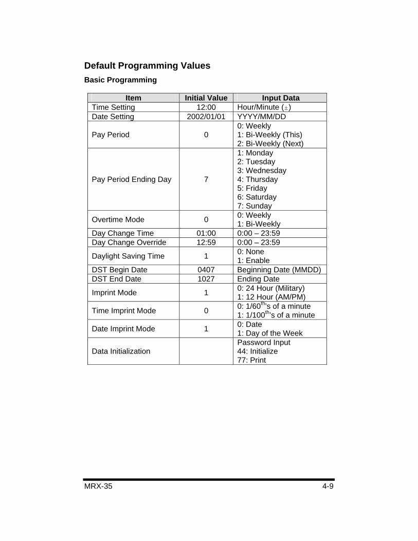
Default Programming Values Basic Programming
Item Initial Value Input Data Time Setting 12:00 Hour/Minute ( )Date Setting 2002/01/01 YYYY/MM/DD
Pay Period 0 0: Weekly 1: Bi-Weekly (This) 2: Bi-Weekly (Next)
Pay Period Ending Day 7
1: Monday 2: Tuesday 3: Wednesday 4: Thursday 5: Friday 6: Saturday 7: Sunday
Overtime Mode 0 0: Weekly 1: Bi-Weekly
Day Change Time 01:00 0:00 – 23:59 Day Change Override 12:59 0:00 – 23:59
Daylight Saving Time 1 0: None 1: Enable
DST Begin Date 0407 Beginning Date (MMDD) DST End Date 1027 Ending Date
Imprint Mode 1 0: 24 Hour (Military) 1: 12 Hour (AM/PM)
Time Imprint Mode 0 0: 1/60th’s of a minute 1: 1/100th’s of a minute
Date Imprint Mode 1 0: Date 1: Day of the Week
Data Initialization Password Input 44: Initialize 77: Print
4-10 MRX-35
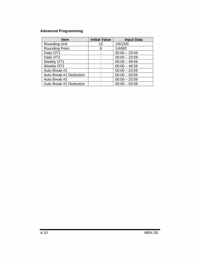
Advanced Programming
Item Initial Value Input Data Rounding Unit 15 1/6/15/0 Rounding Point 8 1/4/8/0 Daily OT1 : 00:00 – 23:59 Daily OT2 : 00:00 – 23:59 Weekly OT1 : 00:00 – 49:59 Weekly OT2 : 00:00 – 49:59 Auto Break #1 : 00:00 – 23:59 Auto Break #1 Deduction : 00:00 – 03:59 Auto Break #2 : 00:00 – 23:59 Auto Break #2 Deduction : 00:00 – 03:59
MRX-35 5-1
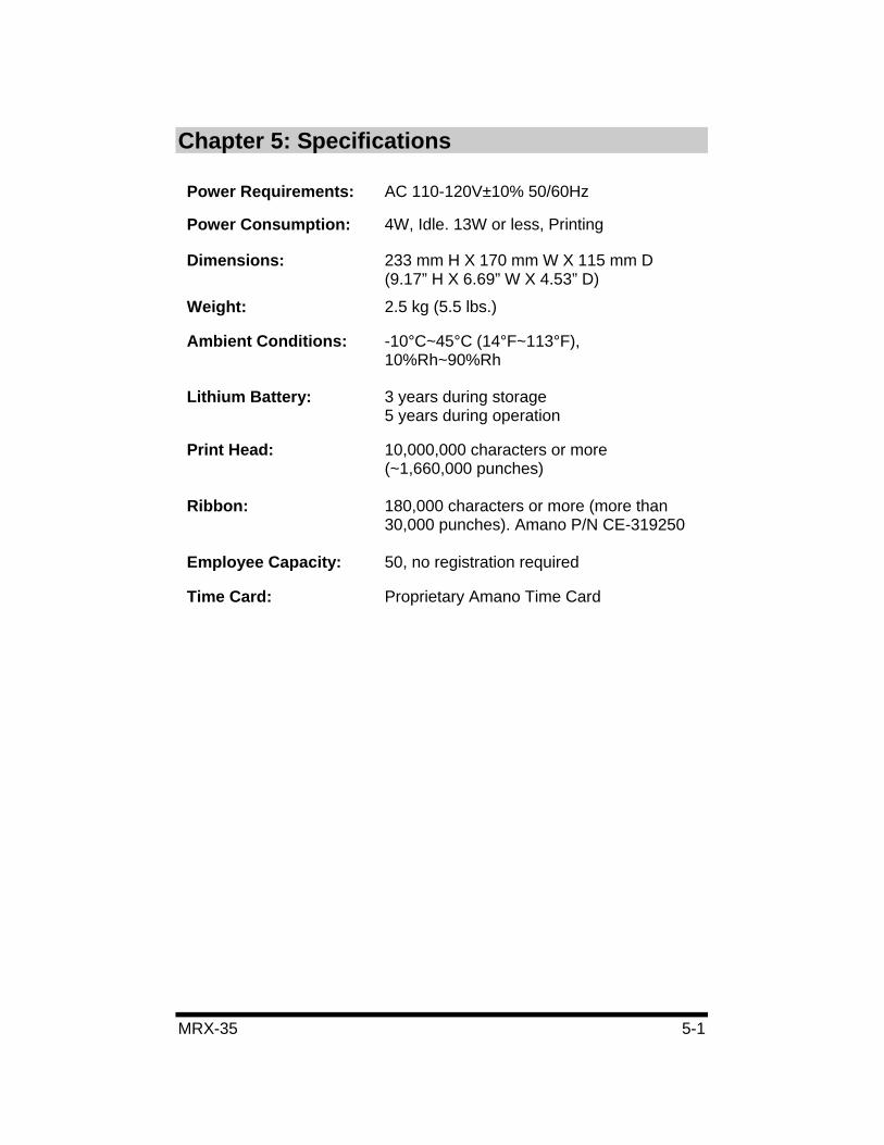
Chapter 5: Specifications
Power Requirements: AC 110-120V±10% 50/60Hz
Power Consumption: 4W, Idle. 13W or less, Printing
Dimensions: 233 mm H X 170 mm W X 115 mm D (9.17” H X 6.69” W X 4.53” D)
Weight: 2.5 kg (5.5 lbs.)
Ambient Conditions: -10°C~45°C (14°F~113°F), 10%Rh~90%Rh
Lithium Battery: 3 years during storage 5 years during operation
Print Head: 10,000,000 characters or more (~1,660,000 punches)
Ribbon: 180,000 characters or more (more than 30,000 punches). Amano P/N CE-319250
Employee Capacity: 50, no registration required
Time Card: Proprietary Amano Time Card

5-2 MRX-35


ARX-100900 Copyright ©2004 Amano Cincinnati, Inc. Printed in U.S.A. 1/04/500