accelerator driven transmutation · accelerator driven transmutation chairman: ... the chinese...
TRANSCRIPT
371
SESSION V
ACCELERATOR DRIVEN TRANSMUTATION
CHAIRMAN: T. MUKAIYAMA
CO-CHAIRMAN: M. DELPECH

373
SESSION VCHAIRMAN: T. MUKAIYAMA
The highlights of the OECD-NEA Workshop on “Utilisation and Reliability of High Power ProtonAccelerator” at Mito, Japan on October 13 - 15, 1998 were reported.
• The objective of the workshop was to explore the efficient utilisation of high power protonaccelerator (HPPA) in various fields and the future possibility of accelerator-driven subcriticalsystems (ADS).
• One serious problem is frequent beam trips of existing HPPAs. It is indispensable to understandthe effects of beam trips on sub-systems, especially on ADS.
• For ADS application, beam trips should be reduced by two order of magnitudes.
• These severe requirements from ADS to HPPA are completely new for the acceleratorcommunity.
• Development of a reference subcritical system was recommended for benchmark analysis ofpossible problems.
• The comparison between Linear and Circular accelerators was discussed, and the conclusion wasthe following: (1) a linac was for tens mA and GeV, (2) a linac or a cyclotron was for 10 mA, and(3) a cyclotron was for less than 10 mA.
Effect of beam trips on sub-systems was investigated for the fuel pin and beam window in JAERI. Itwas concluded that fatigue damages caused by beam trips were negligible.
The CEA/EDF paper and the KAERI paper discussed the comparison between thermal neutronspectrum and fast neutron spectrum. They concluded that thermal neutron spectrum is not adequatefor ADS because its short mean free path causes localisation of nuclear reactions which is notacceptable for safe operation of ADS. The former paper also discussed the comparison of coolantmaterials for a demonstration device of ADS and concluded that a gas cooled system is the firstpriority, lead-bismuth is the second, and the sodium.
SCK/CEN of Belgium proposes a medium-size ADS prototype, MYRRHA. The spallation target is aliquid lead-bismuth with a unique windowless design. The subcritical core is made of two consecutivezones of fast and thermal zone.
Conceptual safety analysis was carried out for the Fast Energy Amplifier design (ANP, Italy). For theanalysis, three-dimensional simulation was carried out using MCNP since the point kinetic analysiscannot be applicable due to the existence of higher mode for ADS.


375
HIGHLIGHT OF OECD/NEA WORKSHOPON “UTILISATION AND RELIABILITY OF HIGH POWER PROTON ACCELERATOR”
N. Watanabe, Y. Oyama and T. MukaiyamaJapan Atomic Energy Research Institute
Tokai-mura, Naka-gun, Ibaraki-ken 319-1195,Japan
Abstract
The first OECD/NEA Workshop on “Utilisation and Reliability of High Power Proton Accelerator”was held at Mito, Ibaraki, in Japan on October 13 -15, 1998. The participants were 92 persons,including 32 persons from the outside of Japan. There were two keynote talks and eleven invited talksfrom the high power proton accelerator (HPPA) projects. Twenty three technical papers werepresented about the areas related to reliability of HPPA, new accelerators, effects of beam trips, andinterface technologies. Technical discussion sessions were also arranged for accelerator andaccelerator driven system (ADS), in parallel. In the last panel session, the commentators from bothfields commented on technical problems.
376
Scope of the workshop
R&D activities and construction plans related to high power proton accelerators (HPPAs) arebeing considered in various countries to promote basic and applied sciences, including accelerator-driven nuclear energy system (ADS), using neutrons, protons and other secondary particles. Takinginto account the fact that proton beams from existing HPPA trip (suddenly stop) very frequently, it isindispensable to understand the effects (e.g. thermal shocks) of such beam trips on different sub-systems, especially fission sub-systems. Additional R&D will be needed to accomplish a highlyreliable HPPA and sub-systems resistant to thermal shocks.
The scope of the workshop comprises:
− The experiences and prospects of HPPA utilisation.
− Reliability of existing HPPAs, especially focused on beam trips and power fluctuations.
− Effects of resulting thermal shocks in fission sub-systems.
− Required accelerator reliability in various applications.
− R&D of sub-systems resistant to such shocks.
− Accelerator types suitable for ADS, interface technology between proton beam and sub-systems.
− Control system and safety concept for ADS and problems relevant to utilisation (multi-purpose vs. dedicated systems, etc.).
The purpose of the workshop is to exploit more efficient utilisation of HPPAs in various fieldsand to ensure the future possibility of ADS.
Major Presentations
Applications of High Power Proton Accelerators (HPPA)
Five presentations were given to the projects developing spallation neutron sources with HPPA,and six presentations to the accelerator driven system (ADS) with HPPA.
The SNS project in USA was approved, which aims at 1 MW pulsed spallation neutron sourcefor neutron scattering and will be upgraded to 4 MW. The ESS project for 5 MW spallation neutronsource in Europe has started an optional study of a superconducting proton linac, in addition to thereference normal conducting one. There are two projects in Japan and it was reported that bothprojects will join: the JAERI Neutron Science Project for neutron science and for transmutation oflong-lived nuclear wastes with 1.5 GeV-5.3 mA superconducting linac, and the JHF project promotedby High Energy Accelerator Research Organisation (KEK) which includes two ring synchrotrons of3 GeV-200 mA and 50 GeV and four research facilities, i.e., for high energy nuclear physics, neutronscattering, muon science and RI beam nuclear physics. The KOMAC project in Korea is amultipurpose accelerator complex aims at constructing a 1 GeV-20 mA HPPA in conjunction withADS project of HYPER.
Many countries have ADS oriented projects. The Chinese project of a 150 MeV-3 mA HPPA isinjecting a beam to 3.5 MWt LWR with criticality of 0.94-0.98. Russian activities of ADSdevelopment includes critical experiment with photo neutrons from a Pb or Pb-Bi target. The Czech
377
program is for LLFP and TRU transmutation with mixture of target/MA and Flibe cooledgraphite/LLFP blankets driven by a 35 MeV deuteron external neutron source. In France, there areGEDEON activities of development for nuclear waste transmutation. Those include spallation targetexperiments at SATURN and reactor experiments at MASURCA with a 14 MeV source, materialresearch of structure and Pb , Pb-Bi target and 10 MeV-100 mA accelerator developments. Italy hasTRASCO program by ENEA and INFN, and the industrial program by Ansaldo Corp. The TRASCOis developing a 1 GeV-30 mA accelerator, subcritical system like Energy Amplifier with nine sub-programs. The industrial program is focusing on a demonstration proto-type of an 80 MWt, a Pb-Bitarget and subcriticality of 0.95. In USA, the ATW is conducting three blocks of developments:accelerator in APT (1 GeV-140 mA), pyrochemical processes and a subcritical burner(2000 MWt/Pb-Bi).
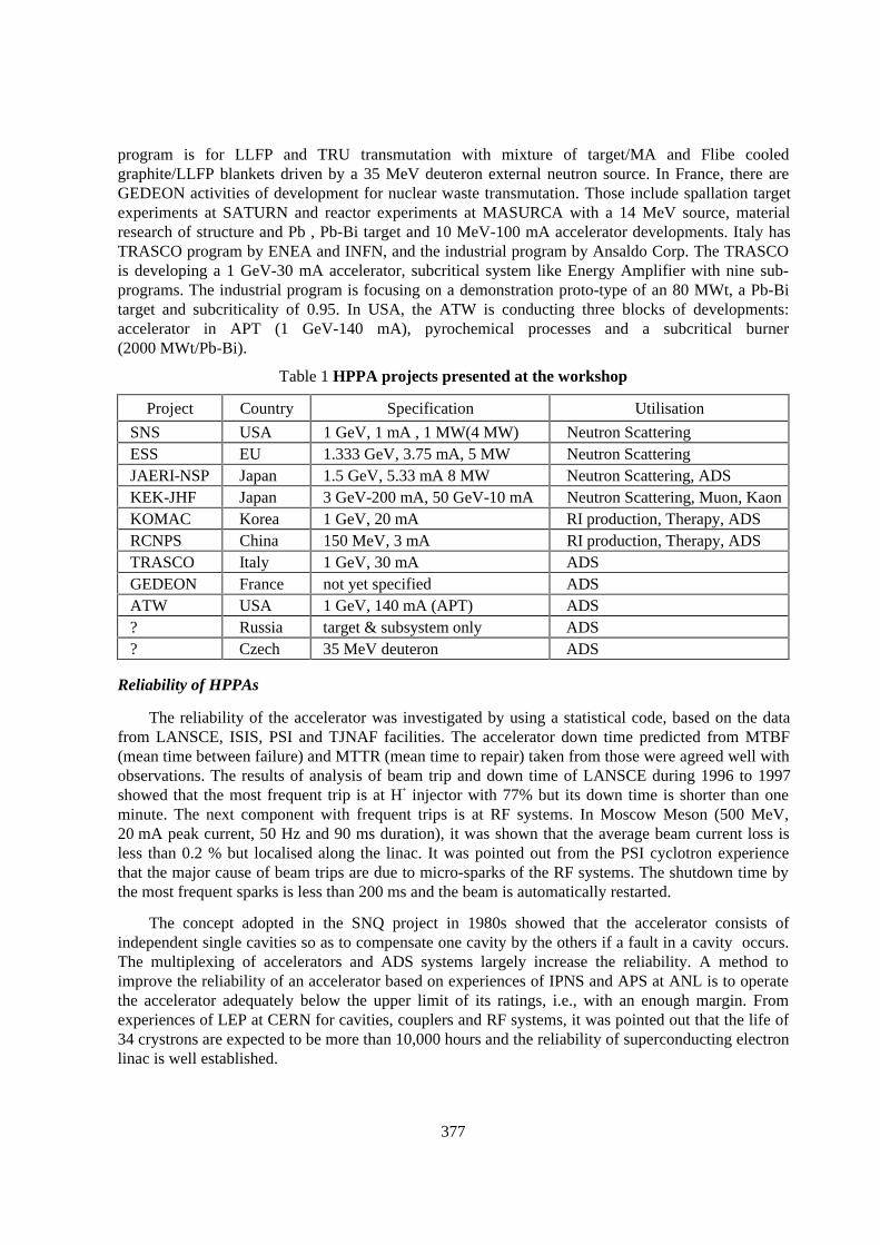
Table 1 HPPA projects presented at the workshop
Project Country Specification Utilisation
SNS USA 1 GeV, 1 mA , 1 MW(4 MW) Neutron ScatteringESS EU 1.333 GeV, 3.75 mA, 5 MW Neutron ScatteringJAERI-NSP Japan 1.5 GeV, 5.33 mA 8 MW Neutron Scattering, ADSKEK-JHF Japan 3 GeV-200 mA, 50 GeV-10 mA Neutron Scattering, Muon, KaonKOMAC Korea 1 GeV, 20 mA RI production, Therapy, ADSRCNPS China 150 MeV, 3 mA RI production, Therapy, ADSTRASCO Italy 1 GeV, 30 mA ADSGEDEON France not yet specified ADSATW USA 1 GeV, 140 mA (APT) ADS? Russia target & subsystem only ADS? Czech 35 MeV deuteron ADS
Reliability of HPPAs
The reliability of the accelerator was investigated by using a statistical code, based on the datafrom LANSCE, ISIS, PSI and TJNAF facilities. The accelerator down time predicted from MTBF(mean time between failure) and MTTR (mean time to repair) taken from those were agreed well withobservations. The results of analysis of beam trip and down time of LANSCE during 1996 to 1997showed that the most frequent trip is at H+ injector with 77% but its down time is shorter than oneminute. The next component with frequent trips is at RF systems. In Moscow Meson (500 MeV,20 mA peak current, 50 Hz and 90 ms duration), it was shown that the average beam current loss isless than 0.2 % but localised along the linac. It was pointed out from the PSI cyclotron experiencethat the major cause of beam trips are due to micro-sparks of the RF systems. The shutdown time bythe most frequent sparks is less than 200 ms and the beam is automatically restarted.
The concept adopted in the SNQ project in 1980s showed that the accelerator consists ofindependent single cavities so as to compensate one cavity by the others if a fault in a cavity occurs.The multiplexing of accelerators and ADS systems largely increase the reliability. A method toimprove the reliability of an accelerator based on experiences of IPNS and APS at ANL is to operatethe accelerator adequately below the upper limit of its ratings, i.e., with an enough margin. Fromexperiences of LEP at CERN for cavities, couplers and RF systems, it was pointed out that the life of34 crystrons are expected to be more than 10,000 hours and the reliability of superconducting electronlinac is well established.
378
New Accelerators
A H2
+ cyclotron concept was proposed to reduce the space charge effect and to eliminatedeflection by a stripping foil. A separated orbit cyclotron with superconducting magnets and cavitieswas also proposed with the results of the test device TRITRON, in which three cascade rings canaccelerate the beam up to 1 GeV. A FFAG (fixed field alternating gradient) accelerator was proposedto improve power efficiency of accelerator for ADS, because of the context of progress in cavity andmagnet technologies.
Beam Trips/Fluctuations: Effect on ADS and ADS Resistance
From a preliminary analysis on a modest design concept of ADS, it was shown that thermo-mechanical effect on ADS components is the most important problem of the trip, but the effects onfuel pellets, fuel pins and beam window would be negligible. It was also shown from the results oftemperature transient test for making structural design guide in FBR, that in repetition of temperaturevariation between 250°C and 600°C, the test piece was damaged by thermal fatigue for short periodof cycles and by creep fatigue for long period of cycles.
From the analysis of the components with temperature variation during the trip based on the EFRconcept, it was pointed out that above core structure (ACS) and intermediate heat exchanger (IHX)were important components for such analysis.
Interface Technology
In the IFMIF analysis, a decay constant of Li temperature is a few minutes for the two kinds oftrips of two deuteron beam injections with 40 MeV-250 mA: two beams of 10 MW and one beam of5 MW.
In transient thermal stress analysis in the window of mercury target made of SS316 steel,bombarded by pulsed-protons at a beam power of 5 MW with 50 Hz, it was shown that an asymptotictemperature at the beam window was quickly achieved within a couple of seconds, although thetemperature fluctuates at 50 Hz.
A temperature decay constant in the lead incore and the cladding for a lead rod target isestimated to be 5-10 s for unscheduled beam trip or loss of coolant. Maximum stress was 90 MPa inthe cladding through normal operation and beam trip transient.
In the lead-bismuth spallation target at a proton beams of 600 MeV-6 mA, the thermal stressesdecoupled by the fluid dynamic transient showed the Mises stress (conserved quantity related to yieldfunction) of 175 MPa and a fatigue damage induced by cyclic beam trip longer than 4-5 s leads topredict the allowable number of interruptions to failure.
379
Discussions
Parallel Discussion/Accelerator
The items discussed here were:
1. Origin of beam trips and fluctuations
2. Possible improvements for HPPA
3. Achievable reliability in future and necessary R&D
4. Linear vs. Ring accelerators as HPPA systems.
And the major conclusions are the followings:
1. For Beam trips, three types were categorised as: 1) short ( < 1 min.), 2) medium (1 min. -1 h), 3) long (>1 h). The most frequent trip is type (1). Most of (1) and (2) are caused bysparks in HV/RF systems. The down time of micro-spark is typically 100 ms, according toPSI data, and its recovery time is 600 ms. The frequency of trips depends on machine.
2. For possible improvements, to reduce sparks (then to reduce damage), it is considered todesign carefully the devices and controls, to build and maintain as clean room, to keep goodconditioning. The micro-sparks are not avoidable. It is important to note that accelerators arenormally tuned to get maximum and “possibly more” performances, and this is the mainreason of trips and faults.
3. To get reliability, overdesign is necessary, i.e., the same concept applied to the HV/RFsystems should also be applied the other components besides those. The reliable acceleratoris possible, but the meaning of “reliability” should be agreed. The participants agreed with:1) MTBF (mean time between failures) can be reduced to about 100 hrs, and 2) MTTR(mean time to repair) depends on spares and redundancy, i.e., cost.
4. It is important to rely as much as possible on proven accelerators and to select consideringspecific application. For CW machines, “dream” cyclotron (1 GeV, 10 mA) was discussedand general opinions were collected. “Halo” aspect, as most important technical issue, wasstressed. The compactness, modulability, flexibility and so on were also discussed as well asachievable power.
Parallel Discussion/ ADS and Sub-Systems
The discussion were summarised in the following categories:
(A) Definition and separation of problems
− System Test Facility (STF) vs. Transmutation Plant (TP).
− Driven Facility (DF) vs. Spallation Target (ST).
− Nature of trips.
(B) Issues not definitely resolved
(C) Issues not discussed but that need to be considered.
380
And the major conclusions are the followings.
(A) STF is defined as a demonstrator of combination of a subcritical facility with anaccelerator. Only one reliable accelerator will be utilised in this case. The facility shouldhave the maximised flexibility. TP is defined as the facility routinely carrying out actinidetransmutation. The multiplexing of ADSs and HPPAs is conceivable, it is optimised forcost and reliability. In discussion, separated coolant loops are assumed for DF and TP. DFconsists of above core structure (ACS), intermediate heat exchanger (IHX), primarycoolant piping(PCP), fuel core (FC), etc. TP has a beam window and a liquid or solidspallation target. Trips are separated into two time ranges: 1) shorter than a systemcharacteristic time t (40-60 sec or less) and 2) much longer than t. In the case of 1), self-recovering (automated) is considered and effect mainly takes place in ACS or PCP. In thecase of 2), special restart protocol is necessary.
(B) Effect of pulse operation of accelerator and possible restriction to pulse structure were notclearly discussed. These questions are related to economy, possibility of multiplexing andbeam control.
(C) The necessity of control rod in ADS needs to be discussed, relating to compensation ofburn up and a safety device. Controllability of beam power and power surge are also to bediscussed. Specific questions, partial Loss of Beam (LOB) for multiplexing, direct/indirectfeedback of electricity to the system, and construction philosophy, were also left withoutany discussion.
Summary
The conclusions and recommendations from the workshop are summarised as follows:
[1] Required accelerator reliability
[2] Siginificant reduction of beam trips is inevitable for ADS application. (two order ofmagnitude) Regulatory requirement is to be considered. It may be comparable to “CriticalReactor”. If once unscheduled stops happen, a long period will be needed to restart.Specially at the beginning of commissioning it should be very stable to get reliance on thetechnology. Power control must be studied.
[3] Achievable accelerator reliability
[4] MTBF (mean time between failures) can be reduced to about 100 hrs (85 trips/y) usingrecent technology.
[5] R&D needs in HPPA
[6] MTBF has not been important issue for current use of existing HPPAs. Severe requirementfrom ADS is completely new for the accelerator community. Beam trip that will cause theADS restart would be less than once a year.
[7] R&D needs in ADS
[8] A reference subcritical system should be developed for benchmark analysis to get commonunderstanding of possible problems. A way how to control ADS power level must bestudied. Whether keff has to be stable or changeable should be discussed. R&D on structuralmaterials for frequent thermal shock is required.
[9] Linear vs. Circular Accelerators
381
[10] It depends on current, power, energy. A linac is for tens mA and GeV, a linac or acyclotron is for 10 mA and a cyclotron is for less than 10 mA. Beam shape and “Halo” arealso to be considered. At the same time, a good core with stable keff is necessary.
[11] Multiplexing vs. Single Accelerator
[12] It is to be considered from the cost, the reliability and the number of components. The STFmay be one accelerator and TP has options. The key question is economy and reliability inthe commercial operation, including repairing and maintenance.
[13] Dedicated or Multi-purpose Facility
[14] A multi-purpose facility, such as JAERI-NSP and JHF, aims at multi-disciplinary or cross-disciplinary. Secondary particles such as neutrons and also muons are the purpose ofHPPA utilisation. Many dedicated facilities are not allowed especially for small countries.But ADS is not in this domain. It is important to make a dedicated facility to demonstrateADS as a promising system to a society.
[15] Future Collaboration
[16] International collaboration is fruitful to contest the ideas and to reduce the R&D cost.Large number of R&D could be shared. The frame work of OECD/NEA is also useful.
[17] Next OECD/NEA workshop will be held on November 1999 at Cadarache in France.

383
STUDIES ON ACCELERATOR-DRIVEN TRANSMUTATION SYSTEMS
T. Takizuka, T. Sasa, K. Tsujimoto, and H. TakanoJapan Atomic Energy Research Institute
Tokai-mura, Ibaraki-ken, 319-1195,Japan
Abstract
Research and development on transmutation of long-lived radioactive nuclides are being carried outwith an emphasis placed on the dedicated accelerator-driven systems at the Japan Atomic EnergyResearch Institute (JAERI) under the Japanese long-term program for research and development onpartitioning and transmutation technology (OMEGA Programme). The preliminary design of thesodium-cooled solid system has been developed as a reference system based on the current LMFBRtechnology. Concurrently with the study on the sodium-cooled system, we made a preliminary designstudy of lead-bismuth cooled system as an option. Transient responses of temperatures and stressesdue to accelerator beam trips were evaluated for the fuel pin and the beam window of the proposedexperimental facilities
384
Introduction
Research and development on transmutation of long-lived radioactive nuclides are being carriedout with an emphasis placed on dedicated accelerator-driven systems at the Japan Atomic EnergyResearch Institute (JAERI) under the Japanese long-term program for research and development onpartitioning and transmutation technology (OMEGA Program). Design studies are being made foraccelerator-driven transmutation systems (ADTSs). Design of the current reference ADTS followsthat of contemporary sodium cooled fast breeder reactors (FBRs). The major reasons to chose sodiumas coolant are its excellent thermal performance and technology maturity. However, a preliminarydesign study was recently started for a heavy liquid-metal cooling option of ADTS at JAERI. Monju(714-MWt sodium cooled prototype fast reactor) suffered a leakage and fire of secondary sodium inDecember 1995. This incident has caused the people to feel concern about safety of sodium coolanttechnology and stimulated much interest in alternative coolant options, such as lead, lead-bismuth,and He, for fast reactors. The main purposes of the design study of heavy liquid-metal cooling optionare to determine the performance, to assess the feasibility and to identify the technical issues of aheavy liquid-metal cooled design in comparison with the sodium cooled reference design.
The ADTS was specially designed to transmute minor actinides (MAs) from about 10 units of3000-MWt light water reactor (LWR) in a hard neutron energy spectrum and a high neutron flux.Such dedicated transmuter can be very efficient and effective for MA transmutation. In this context,JAERI has been pursuing the strategy of transmutation with dedicated transmuters, rather thanrecycling to commercial power reactors and proposing a concept of a double-strata fuel cycleconsisting of a power reactor fuel cycle (the first stratum) and a P-T cycle (the second stratum) [1,2].In this scenario, a reprocessing plant, a partitioning plant and a dedicated transmuter will be co-located in one site.
The experimental program for development and demonstration of ADTS technology is beingplanned under the JAERI Neutron Science Project. Pre-conceptual design study is being made for theexperimental facilities (30 – 60 MWt experimental system and high-power target experimentalfacility). Large fluctuations and frequent trips of the incident proton beam may be inevitable in thesefacilities. These changes in beam intensity will cause changes in temperatures and stresses in reactorcomponents. This will introduce thermal stress problems related specifically to accelerator-drivensystem. To assess the impact on the structural integrity and lifetime of the components, transientresponses of temperatures and stresses were evaluated for the fuel pin and the beam window of theexperimental system.
Conceptual design study of transmutation systems
The concepts of ADTS have been developed at JAERI. The ADTS is specially designed fortransmutation purpose as a dedicated transmuter to be deployed in the P&T cycle of the double-stratafuel cycle. In the proposed ADTS, an actinide loaded subcritical core is driven by a high-intensityproton accelerator with several tens of MW beam and uses fast neutrons for efficient and effectivetransmutation of actinides. The current design aims at supporting about 10 units of large-scale LWRswith 1000-MWe capacity.
The preliminary design of the sodium-cooled solid system has been developed as a referencesystem based on the current sodium cooled FBR technology. The reference system employs solidtungsten for the spallation target and MA mononitride for fuel of subcritical core. Nitride is adoptedas the fuel material because of its excellent thermal property. The other advantage of nitride fuel isthat it can be processed with the pyrochemical reprocessing, [3] and, hence, the fuel cycle facilitiescan be very compact and cost effective.
385
Recently, JAERI started a design study of a heavy liquid-metal cooled ADTS as an alternativepossible option to re-evaluate its technical viability. Although the heat transfer capability of lead orlead-bismuth is inferior to that of sodium, it has several advantages as coolant for accelerator-driventransmutation systems. Liquid lead or lead-bismuth is particularly suited to the target material, thiseliminating the need for a distinctive solid target. It also offers the possibilities to achieve a harderneutron energy spectrum and to avoid a positive void reactivity coefficient. Intermediate heatexchangers and secondary heat transport loops will possibly be eliminated with lead or lead-bismuthcoolant. Lead-bismuth eutectic coolant offers much lower system operating temperatures than leadcoolant. The lower operating temperature will alleviate the severe problems of materialcorrosion/erosion in heavy metal coolants.
A computer code system ATRAS has been developed for the design of accelerator-driventransmutation system. [4] The cascade code NMTC/JAERI [5] simulates the proton-induced nuclearspallation, subsequent internuclear transport process for energies above 20 MeV. It also calculateshigh-energy fission reaction as a competing process with evaporation. Neutronic calculation below20 MeV is carried out using transport codes, TWODANT and MCNP4A. The time evolution processof transmutation products is calculated by SPCHAIN code and by BURNER code for energies aboveand below 20 MeV, respectively.
Sodium cooled accelerator-driven transmutation system
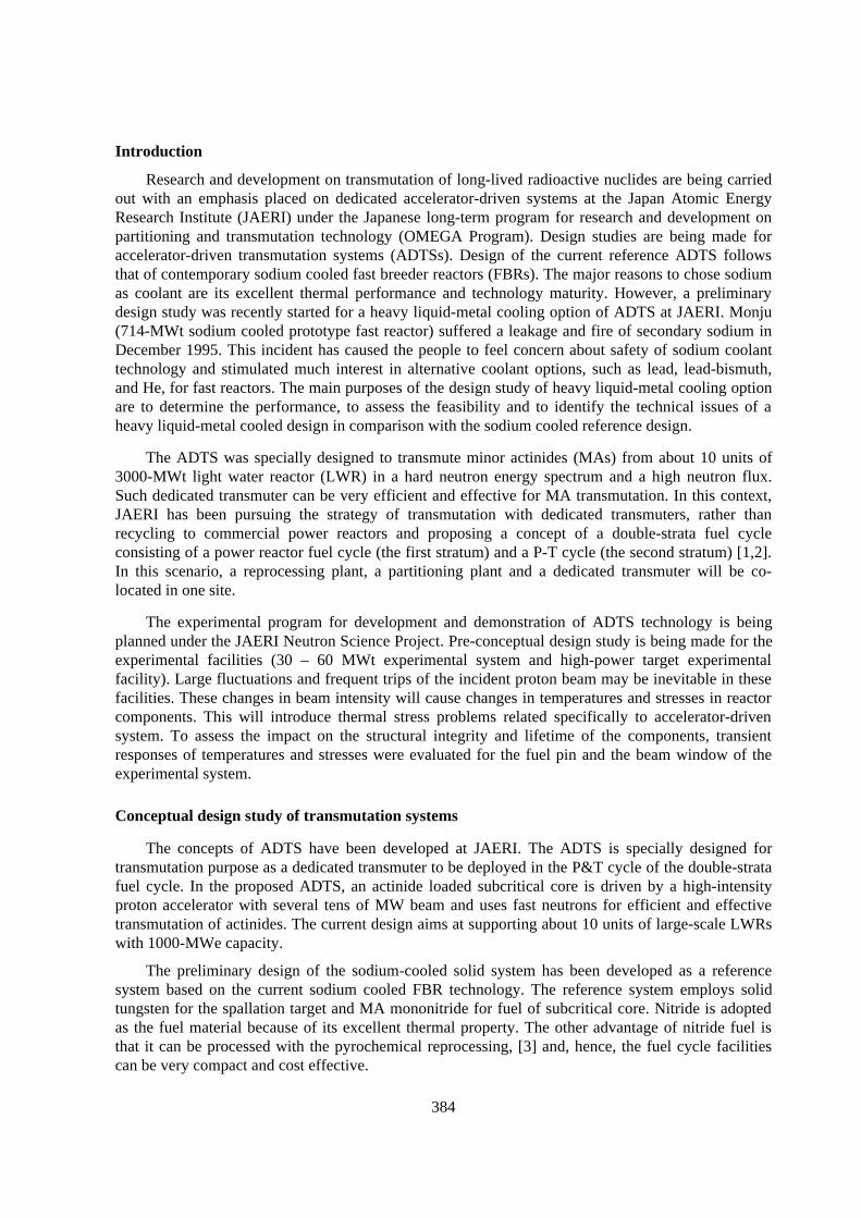
The design of the sodium cooled solid system is based on a sodium cooled FBR. Proton beam isinjected through a beam window into the tungsten target at the center of the target/core. Thesubcritical core loaded with actinide nitride fuel surrounds the target. The target consists of multiplelayers of tungsten disk with through holes for coolant passage. The target is designed to maximise theneutron yield and to flatten the axial power distribution. The target and fuel subassemblies are cooledby forced upward flow of primary Sodium. Impinging flow of coolant from the target exit cools thebeam window. The concept of the sodium cooled solid system is shown in Figure 1.
Figure 1 Sodium cooled ADTS concept
386
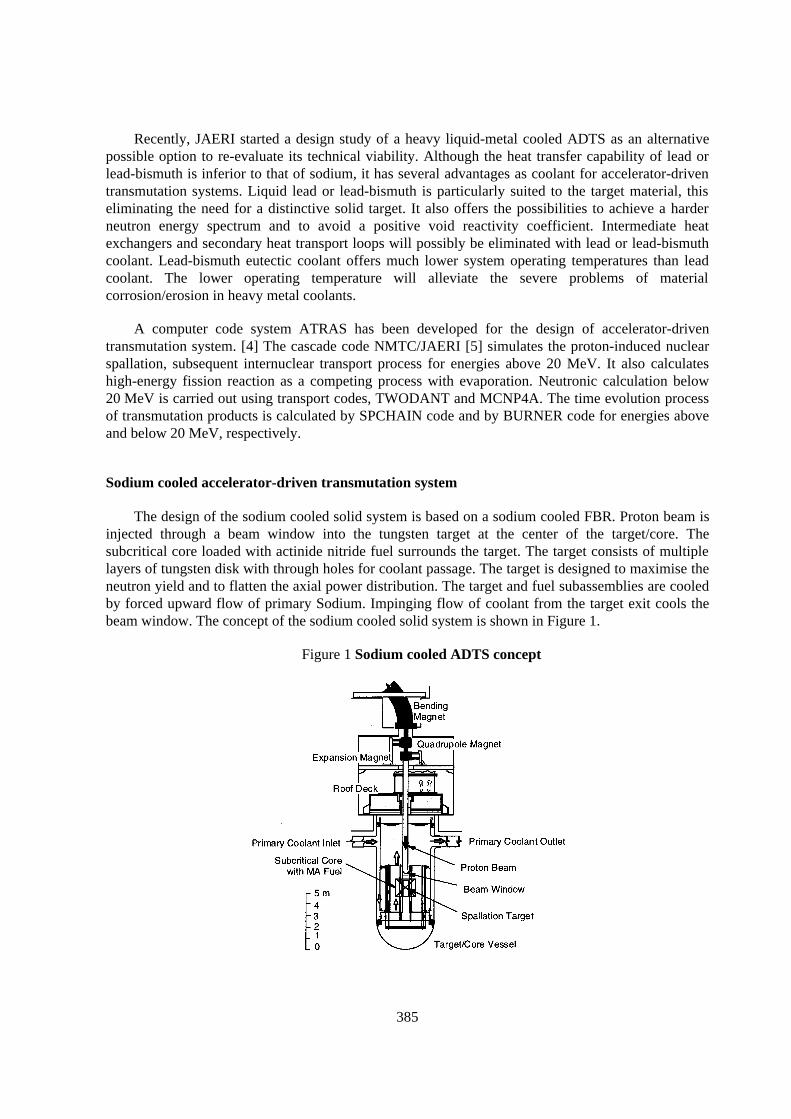
Table 1 Major parameters of the sodium cooled ADTS
MA/Pu Inventory 1950/1300 kgkeff (Initial/Max./Min.) 0.93/0.94/0.92Sodium Void Coefficient +4.5% dk/kDoppler Coefficient -2.2×10⁻⁴ T dk/dTThermal Power 820 MWTransmutation RatePower Density (Max./Ave.)
250 kg/y550/380 MW/m3
Coolant Temperature (In/Out) 330/430 °CCoolant Velocity (Max.) 8 m/s
With a 1.5 GeV - 33 mA incident proton beam, the target/core having an effective neutronmultiplication factor of around 0.95 produces 820-MW thermal power. The net MA transmutationrate is approximately 10%/y, at a plant load factor of 80%. Heat transport and power conversionsystems in the plant design are similar to those for a sodium cooled FBR plant. Electricity of 270 MWis generated through conventional steam turbine. One third of electric power is supplied to its ownaccelerator operation. The major parameters and the schematic diagram of the ADTS plant are shownin Table 1 and Figure 2, respectively.
Figure 2 Schematic diagram of the sodium cooled ADTS plantSuperconducting Proton Linac
to Grid
Alternator
Condenser
Feed Pump 2ry Pump 1ry Pump
Steam Turbine
Proton Beam 1.5 GeV - 33 mA, CW
Intermediate Heat Exchanger
Beam Window
Spallation Target
Subcritical Core with MA Fuel
Steam Generator
2ry Na 1ry Na
100 MWePRACS
170 MWe
270 MWe
Steam
k eff ~0.95
820 MWt
Lead-Bismuth cooled accelerator-driven transmutation system
There are several advantages of heavy liquid metal coolants (lead or lead-bismuth) for fastneutron systems in comparison with sodium coolant, though their thermal property is inferior to thatof sodium. In accelerator transmutation systems, lead or lead-bismuth can play roles of both coolantand spallation target material. Their neutron slowing down power is smaller than that of sodium, andhence neutron spectrum becomes harder in the lead or lead-bismuth cooled core. The hard spectrum ispreferable for MA transmutation. Their chemical inertness is particularly attractive for safety. Thisalso offers the possibility to eliminate secondary heat transport loops.
387
Corrosion which is one of the most important problems in lead or lead-bismuth cooled systems issignificant at high temperatures. The melting point of lead-bismuth is almost the same as that ofsodium while that of lead is considerably higher. So, we selected the lead-bismuth as the coolantmaterial for the dedicated ADTS.
In this study, we investigated the basic characteristics of lead-bismuth cooled ADTS, such as thechange of the multiplication factor, the fuel composition change and the transmutation rate. The MAinventory and the transmutation rate are especially important factors in the transmutation system. It isalso significant to suppress the excess reactivity change during burnup for minimising the change ofthe proton beam current.
Calculation of neutronic characteristics
The survey calculation was performed to investigate the neutronic characteristics of lead-bismuthcooled ADTS. First, the fuel compositions were determined by adjusting the Pu content and thefraction of inert matrix to set the initial subcritical level at 0.95. Second, the burnup calculations weredone for these fuel compositions. The MA transmutation rate and the burnup swing are especiallyimportant to estimate the ADTS performance. The purpose of the survey was to optimise the coreparameters for maximising the MA transmutation rate and minimizing the burnup swing. Thequantitative goals were the MA inventory below 2500 kg, the MA transmutation rate above 10%/y,and the burnup swing below 2% during 10 years full power operation.
The core sizes were determined by heat-balance calculation using the fuel pin pitch to diameterratio (P/D) and coolant velocity as the parameters. The P/D value was varied in the range from 1.5 to1.9. The coolant velocity was varied from 1.2 to 2.0 m/s. In this calculation, the core thermal powerwas assumed to be 800 MW. The coolant temperature rise through the core was set to 100 ºC, and theaverage linear power, 300 W/cm. The core height was fixed at 100 cm and the diameter of thespallation target region was set at 50 cm, in all cases.
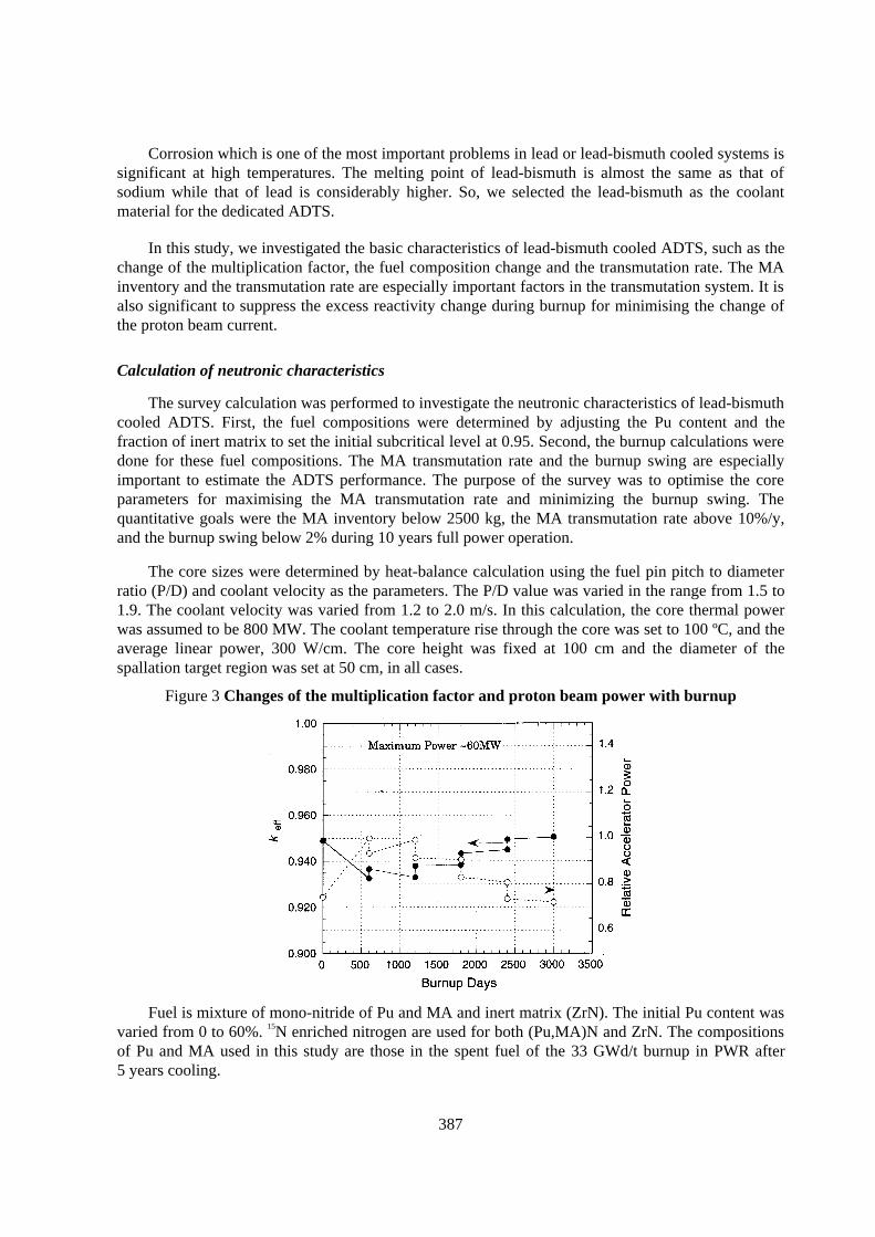
Figure 3 Changes of the multiplication factor and proton beam power with burnup
Fuel is mixture of mono-nitride of Pu and MA and inert matrix (ZrN). The initial Pu content wasvaried from 0 to 60%. 15N enriched nitrogen are used for both (Pu,MA)N and ZrN. The compositionsof Pu and MA used in this study are those in the spent fuel of the 33 GWd/t burnup in PWR after5 years cooling.
388
The multiplication factor was calculated by the diffusion calculation. The group constants of fuelregion were obtained by the collision probability method considering heterogeneous effect by theSLAROM code. [6] The cross section library used in SLAROM was JFS-3 type [7] 70 groupconstants set based on the JENDL-3.2 library. [8] The diffusion calculation was done by the modifiedCITATION code [8].
The burnup calculation was done by the ABC-SC code system. The ABC-SC code systemconsists of SLAROM, CITATION and ORIGEN2. [10] The changes of effective cross section withburnup for about 40 actinide isotopes including the JENDL-3.2.2 library were considered in eachburnup step in ABC-SC. For other isotopes, the values in ORIGEN’s fast reactor library were used.The burnup calculations were done for 5 burnup cycles. We assumed one burnup cycle consists of 2years burnup and 3 years cooling. After the cooling, FPs were removed and MA of equal mass to theFPs was added to the burnup fuel to recycle.
Figure 3 shows the changes of the multiplication factor and the proton beam power for the ADTSwith optimum set of core parameters. In this case, the initial Pu fraction is 40% and P/D is 1.5. Thecoolant velocity is 2.0 m/s, corresponding to the power density of about 180 W/cm3. The figureindicates that the change of proton beam power is about 30%, though the burnup swing in 10 yearsoperation is only 1.8%. The maximum beam power is needed at the maximum system subcriticallevel for constant power operation, corresponding to about 60 MWb.
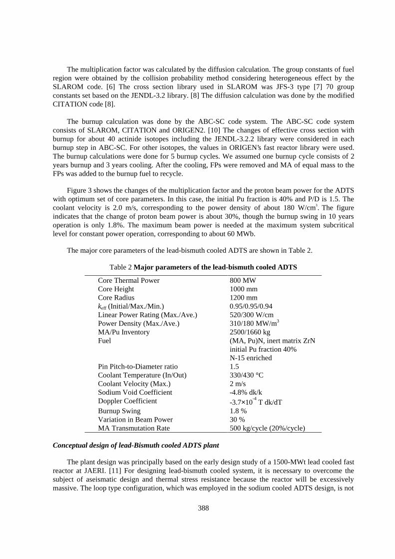
The major core parameters of the lead-bismuth cooled ADTS are shown in Table 2.
Table 2 Major parameters of the lead-bismuth cooled ADTS
Core Thermal Power 800 MWCore Height 1000 mmCore Radius 1200 mmkeff (Initial/Max./Min.) 0.95/0.95/0.94Linear Power Rating (Max./Ave.) 520/300 W/cmPower Density (Max./Ave.) 310/180 MW/m3
MA/Pu Inventory 2500/1660 kgFuel (MA, Pu)N, inert matrix ZrN
initial Pu fraction 40%N-15 enriched
Pin Pitch-to-Diameter ratio 1.5Coolant Temperature (In/Out) 330/430 °CCoolant Velocity (Max.) 2 m/sSodium Void Coefficient -4.8% dk/kDoppler Coefficient -3.7×10
-4 T dk/dTBurnup Swing 1.8 %Variation in Beam Power 30 %MA Transmutation Rate 500 kg/cycle (20%/cycle)
Conceptual design of lead-Bismuth cooled ADTS plant
The plant design was principally based on the early design study of a 1500-MWt lead cooled fastreactor at JAERI. [11] For designing lead-bismuth cooled system, it is necessary to overcome thesubject of aseismatic design and thermal stress resistance because the reactor will be excessivelymassive. The loop type configuration, which was employed in the sodium cooled ADTS design, is not
389
suitable for lead-bismuth cooled system, because it will be difficult to realise the heavy pipingsystem. So, the pool type reactor is selected for the lead-bismuth cooled ADTS. Intermediate heattransport system is possible to be eliminated with lead-bismuth coolant. Cr-Mo steel is used as thestructural material considering the corrosion resistance in lead-bismuth, mechanical strength andductility. The plant heat balance was calculated and the sizes of the primary pumps, the steamgenerators and the core vessel were determined.
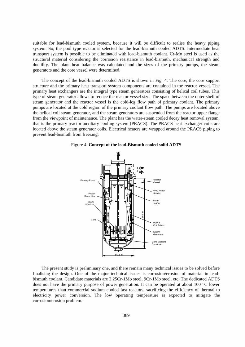
The concept of the lead-bismuth cooled ADTS is shown in Fig. 4. The core, the core supportstructure and the primary heat transport system components are contained in the reactor vessel. Theprimary heat exchangers are the integral type steam generators consisting of helical coil tubes. Thistype of steam generator allows to reduce the reactor vessel size. The space between the outer shell ofsteam generator and the reactor vessel is the cold-leg flow path of primary coolant. The primarypumps are located at the cold region of the primary coolant flow path. The pumps are located abovethe helical coil steam generator, and the steam generators are suspended from the reactor upper flangefrom the viewpoint of maintenance. The plant has the water-steam cooled decay heat removal system,that is the primary reactor auxiliary cooling system (PRACS). The PRACS heat exchanger coils arelocated above the steam generator coils. Electrical heaters are wrapped around the PRACS piping toprevent lead-bismuth from freezing.
Figure 4. Concept of the lead-Bismuth cooled solid ADTS
Primary Pump
Proton Beam Line
Beam Window
Core
Reactor Vessel
Feed Water Header
Steam Header
Helical Coil Tubes
Steam Generator
Core Support Structure
16
.5 m
φ 7.5 m
The present study is preliminary one, and there remain many technical issues to be solved beforefinalising the design. One of the major technical issues is corrosion/erosion of material in lead-bismuth coolant. Candidate materials are 2.25Cr-1Mo steel, 9Cr-1Mo steel, etc. The dedicated ADTSdoes not have the primary purpose of power generation. It can be operated at about 100 °C lowertemperatures than commercial sodium cooled fast reactors, sacrificing the efficiency of thermal toelectricity power conversion. The low operating temperature is expected to mitigate thecorrosion/erosion problem.
390
The beam window suffers from the stress due to the differential pressure between the acceleratorvacuum and system operating pressure. In the lead-bismuth cooled system, the differential pressure ismuch larger due to high density of lead-bismuth than in the sodium cooled system. The pressure loadstogether with thermal stress cause a very difficult problem of beam window mechanical strength. Thisproblem could further worsen in a high flux environment of protons and neutrons.
In lead-bismuth coolant, fuel subassemblies are subjected to upward buoyancy force that is largerthan downward gravitational force. Design measure for mechanical constraint should be needed tokeep the subassemblies fixed.
The problem of 210Po generation by capture reaction of 209Bi arises in lead-bismuth cooled system.The amount of radioactivity in the primary coolant was estimated to be the same level as conventionalfast reactors. The estimation of radioactivity and toxicity of the spallation products is now underway.Some purification system to remove 210Po and spallation products from primary coolant will benecessary.
Effects of accelerator beam trips on fuel pin and beam window
One of the most important effects of beam trips is thermal fatigue of ADS component materials.A beam trip changes temperatures in ADS components. Changes in temperatures causes changes inthermal stresses and thermal strains in the components. Repeated temperature changes (thermalcycling) due to frequent beam trips can cause thermal fatigue of the component materials. Damagescaused by thermal fatigue can lead to degradation of their structural integrity and reduction of theirlifetime. Rather frequent replacement of the components of concern and/or special design measures tomitigate the problem might be required, if the accelerator reliability could not be sufficientlyimproved.
Preliminary analyses were made on thermal and structural responses of a fuel pin and a beamwindow for the experimental facilities [12] planned under the Neutron Science Project.
Analyses of fuel pin
Two-dimensional thermal-hydraulic and structural analyses were made on the single fuel pinwith the average power of the planned 60 MWt experimental system. Conditions of analyses are listedin Table 3.
The maximum fuel temperature calculated is 1 520°C, sufficiently lower than the melting pointaround 2 800°C. Tensile strength of the oxide fuel pellet is around 10 kg/mm2 at 1 500°C. Calculatedmaximum tensile stress of the fuel pellet is around 37 kg/mm2. It is expected that one or two radialcracks will be formed. The cracks will relieve the stress and preventing from further crack formationand propagation.
It is predicted there are no possibilities of tensile/creep rapture of the 316 SS cladding, since theinternal pressure of fuel pin due to gaseous FP release is low. With an appropriate gap, fuel cladmechanical interaction can not occur. The major factor that can affect the integrity of cladding isfatigue caused by thermal cycling.
391
The maximum thermal strain of the cladding is 2.3×10⁻⁴. Since the design fatigue strain range at107 cycles is 10-3 at 430°C, it is evaluated that fatigue damage to cladding is negligible.
Table 3 Conditions of analyses of fuel pin
Fuel UO2
Bond HeliumCladding 316 SSPin Diameter 5.4 mmPin Pitch 7 mmActive Core Height 850 mmCoolant SodiumCoolant Temperature (In/Out) 330/430°C (normal operation, average)Linear Power Rating 120 W/cm (normal operation, average)
Analyses of beam window
Two-dimensional thermal-hydraulic and structural analyses were made on the beam window ofthe planned high-power target experimental facility. The beam window is a hemispherical cap madeof 316 SS, having a radius of 120 mm and a thickness of 1 mm. The incident proton beam with apower of 7 MW has a diameter of 200 mm and a uniform current density distribution. The beamwindow is cooled by upward flow of sodium coolant. The operating pressure of the sodium coolant atthe level of the beam window is 3 Mpa.
The maximum operating temperature calculated is 525°C, and the temperatures at evaluatedcross sections are in the range from 340 to 515°C. Results were evaluated for a high-temperatureoperating time of 8 760 h according to “High-temperature Design Guideline for FBR Prototype Class1 Components” (STA) and “Technical Standard for Structures of Nuclear Facilities for PowerGeneration” (MITI).
All stresses and strains are well within their allowable limits, and the allowable number ofoperating cycles is greater than 106. Fatigue damage to the beam window was evaluated to benegligible.
Concluding remarks
A preliminary design study was made for a lead-bismuth cooled accelerator-driven system as anpossible alternative option to the sodium cooled solid system concept based on the current LMFBRtechnology. The core parameters were determined to achieve minimum variation in the effectivemultiplication factor during burnup cycles. Pool-type configuration was selected for the lead-bismuthcooled system from the point of aseismatic design view rather than loop-type used for the sodiumcooled reference system. Major technical problems to be resolved are material compatibility, beamwindow design, etc.
Preliminary analyses were performed on thermal and structural responses of a fuel pin and abeam window during a normal operation and a beam trip transient. It was estimated that fatiguedamages to the fuel cladding and the beam window caused by beam trips are negligible. More detaildesign and further analyses are needed to formulate design considerations, R&D needs, and therequirements of accelerator reliability.
392
REFERENCES
[1] H. Murata and T. Mukaiyama, Atomkern-Energie Kerntechnik, 45, p. 23 (1984).
[2] T. Mukaiyama, Importance of the double strata fuel cycle for minor actinidetransmutation, Proceedings 3rd OECD/NEA Int. Information Exchange Mtg. on P-T, p. 30(Cadarache, 1994).
[3] T. Ogawa et al., Nitride Fuel Cycles on Pyrochemistry, Proceedings. Int. Conf. FutureNuclear Systems, “Global ’97” (Yokohama, 1997).
[4] T. Sasa et al., Conceptual Design Study and Code Development for Accelerator-BasedTransmutation System”, Proceedings Int. Conf. Future Nuclear Systems, “Global ’97”,(Yokohama, 1997).
[5] Y. Nakahara et al., “NMTC/JAERI – A Simulation Code System for High Energy NuclearReactions and Nucleon-Meson Transport Process, JAERI-M 82-198 (in Japanese) (1982).
[6] M. Nakagawa and K. Tsuchihashi, “SLAROM : A Code for Cell HomogenizationCalculation of Fast Reactor”, JAERI 1294 (1984).
[7] H. Takano and Y. Ishiguro, Production and Benchmark Tests of Fast Reactor GroupConstant Set JFS-3~J2, JAERI-M 82-135 (1982).
[8] T. Nakagawa, et al., Japanese Evaluated Nuclear Data Library Version-3 Revision-2 :JENDL-3.2, J. Nucl. Sci. and Technol., 32, 1259 ( 1995).
[9] T. B. Fowler, D. R. Vondy and G. W. Cunningham, Nuclear Reactor Core Analysis Code: CITATION, ORNL-TM-2496 (1969).
[10] A. G. Groff, “ORIGEN-2 : A Revised and Updated Version of the Oak Ridge IsotopeGeneration and Development Code”, ORNL-5621 (1980).
[11] H. Takano et al., A Design Study for Inherent Safety Core, Aseismicity and Heat TransportSystem in Lead-Cooled Nitride-Fuel Fast Reactor, Proceedings ARAA' 94, Pittsburgh,Pennsylvania, April 17-21, 1994, vol. 1 p.549-556 (1994).
[12] T. Takizuka, et al., Accelerator-Driven Transmutation System Demonstration Experimentsat JAERI, Proceedings Int. Conf. Future Nuclear Systems, “Global ’97”, (Yokohama,1997).
393
REACTOR PHYSICS ANALYSIS OF HYBRID SYSTEMS
O. Köberl, G. Ritter, I. Slessarev,J. Tommasi, M. Valade, G. Youinou
DRN/DER/SPRC, CEA/Cadarache,France
J. VergnesEDF/DER, Paris,
France
M. SalvatoresDRN/PP, CEA,
France
P. AnzieuDRN/DER/PAC, CEA/Cadarache,
France
H. MouneyEDF/DE, Paris,
France
D. Verrier, B. CarluecFRAMATOME, Lyon,
France
394
Introduction
This paper presents two different approaches to analyse ADS concepts in order to optimise them.One is based on the analysis of external proposals with CEA codes (SPARTE, ERANOS) and usingthe same data (JEF 2). The second one is a broad study aiming at analysing the physics of differenttechnologies (gas cooled, metal cooled, molten salt,...).
The analysis of hybrid reactors is based on the SPARTE system i.e. the High Energy codemodules developed at CEA/DAM coupled to the ERANOS deterministic set of tools and adjusteddata and the TRIPOLI Monte-Carlo transport code. The data essentially rely on JEF2.2 in the adjustedlibrary ERALIB. These methods are qualified upon the MUSE experimental program in MASURCA,the mock-up facility at CEA - Cadarache.
External proposals analysis
The aim of the analysis of various concept is to compare the transmutation potential based onsame data and method.
The analysis focused on 4 main projects. A solid fuel system like the Energy Amplifier and 3proposals of fluid fuel systems. Each study presents the CEA vision of the proposal and should notsubstitute to the actual project. In all configurations the spallation target is liquid lead.
Energy amplifier
The aim of that study was to take inspiration from a project proposed by CERN (The EnergyAmplifier of C. Rubbia et al.) in order to test the neutronics computation scheme we use forAccelerator Driven Systems. This computation scheme was tailored to the Energy Amplifier withoutany ambition to debate on its performances. We described a few distinctive features of ADS’s amongwhich ϕ* : external neutron source importance in a subcritical core. The neutronics show a behaviourthat is almost common for fast reactors as far as damages, flux and power rating are concerned.However, it seems that the uncertainties coming from DATA bases can affect the reactivity swing dueto irradiation and the nominal values of most reactivity coefficients. This first phase should lead to acollaboration with CERN in the field of R&D related to ADS’s.
Main system feature
Goal=Energy production in the 232Th/233U cycle.Thermal Power: 1.5 GWTh..Proton beam : Ep = 1 GeV, Ip = 12.5 mA.Keff = 0.98Cycle length : 5 years without refuelling. (Burn-up: 115 GWJ/t).Target, Coolant (natural convection) and Reflector : Lead (Total Mass : 104 T).Annular Core with 2 fuel zones + 1 Breeding blanket.Fuel : 233UO2 + 232ThO2.
395
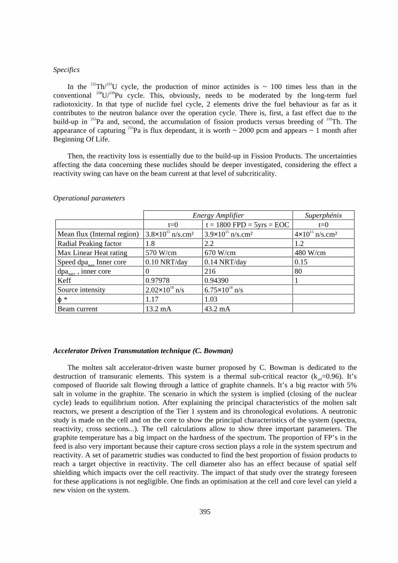
Specifics
In the 232Th/233U cycle, the production of minor actinides is ~ 100 times less than in theconventional 238U/239Pu cycle. This, obviously, needs to be moderated by the long-term fuelradiotoxicity. In that type of nuclide fuel cycle, 2 elements drive the fuel behaviour as far as itcontributes to the neutron balance over the operation cycle. There is, first, a fast effect due to thebuild-up in 233Pa and, second, the accumulation of fission products versus breeding of 232Th. Theappearance of capturing 233Pa is flux dependant, it is worth ~ 2000 pcm and appears ~ 1 month afterBeginning Of Life.
Then, the reactivity loss is essentially due to the build-up in Fission Products. The uncertaintiesaffecting the data concerning these nuclides should be deeper investigated, considering the effect areactivity swing can have on the beam current at that level of subcriticality.
Operational parameters
Energy Amplifier Superphénixt=0 t = 1800 FPD = 5yrs = EOC t=0
Mean flux (Internal region) 3.8×10¹⁵ n/s.cm² 3.9×10¹⁵ n/s.cm² 4×10¹⁵ n/s.cm²Radial Peaking factor 1.8 2.2 1.2Max Linear Heat rating 570 W/cm 670 W/cm 480 W/cmSpeed dpamax Inner core 0.10 NRT/day 0.14 NRT/day 0.15dpaNRT , inner core 0 216 80Keff 0.97978 0.94390 1Source intensity 2.02×10¹⁸ n/s 6.75×10¹⁸ n/sϕ * 1.17 1.03Beam current 13.2 mA 43.2 mA
Accelerator Driven Transmutation technique (C. Bowman)
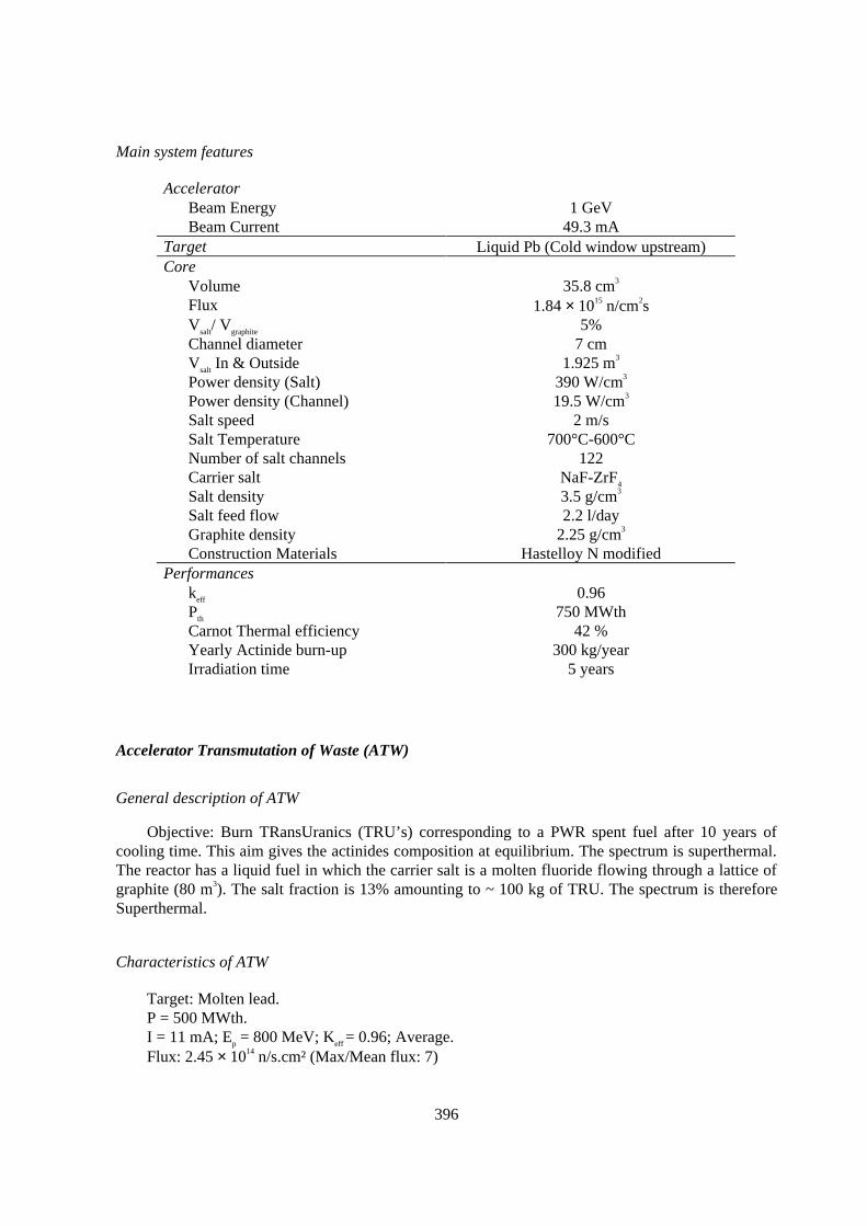
The molten salt accelerator-driven waste burner proposed by C. Bowman is dedicated to thedestruction of transuranic elements. This system is a thermal sub-critical reactor (keff=0.96). It’scomposed of fluoride salt flowing through a lattice of graphite channels. It’s a big reactor with 5%salt in volume in the graphite. The scenario in which the system is implied (closing of the nuclearcycle) leads to equilibrium notion. After explaining the principal characteristics of the molten saltreactors, we present a description of the Tier 1 system and its chronological evolutions. A neutronicstudy is made on the cell and on the core to show the principal characteristics of the system (spectra,reactivity, cross sections...). The cell calculations allow to show three important parameters. Thegraphite temperature has a big impact on the hardness of the spectrum. The proportion of FP’s in thefeed is also very important because their capture cross section plays a role in the system spectrum andreactivity. A set of parametric studies was conducted to find the best proportion of fission products toreach a target objective in reactivity. The cell diameter also has an effect because of spatial selfshielding which impacts over the cell reactivity. The impact of that study over the strategy foreseenfor these applications is not negligible. One finds an optimisation at the cell and core level can yield anew vision on the system.
396
Main system features
AcceleratorBeam Energy 1 GeVBeam Current 49.3 mA
Target Liquid Pb (Cold window upstream)Core
Volume 35.8 cm3
Flux 1.84 × 1015 n/cm2sVsalt/ Vgraphite 5%Channel diameter 7 cmVsalt In & Outside 1.925 m3
Power density (Salt) 390 W/cm3
Power density (Channel) 19.5 W/cm3
Salt speed 2 m/sSalt Temperature 700°C-600°CNumber of salt channels 122Carrier salt NaF-ZrF4Salt density 3.5 g/cm3
Salt feed flow 2.2 l/dayGraphite density 2.25 g/cm3
Construction Materials Hastelloy N modifiedPerformances
keff 0.96Pth 750 MWthCarnot Thermal efficiency 42 %Yearly Actinide burn-up 300 kg/yearIrradiation time 5 years
Accelerator Transmutation of Waste (ATW)
General description of ATW
Objective: Burn TRansUranics (TRU’s) corresponding to a PWR spent fuel after 10 years ofcooling time. This aim gives the actinides composition at equilibrium. The spectrum is superthermal.The reactor has a liquid fuel in which the carrier salt is a molten fluoride flowing through a lattice ofgraphite (80 m3). The salt fraction is 13% amounting to ~ 100 kg of TRU. The spectrum is thereforeSuperthermal.
Characteristics of ATW
Target: Molten lead.P = 500 MWth.I = 11 mA; Ep = 800 MeV; Keff = 0.96; Average.Flux: 2.45 × 10¹⁴ n/s.cm² (Max/Mean flux: 7)

397
Strategy to equilibrium and performances
After one year of operation, the fraction of heavy nuclei in the refueling stream has to be superiorto the fission rate in order to keep Keff at an acceptable level. Otherwise, Keff would rapidly (6 months)fall down to ~ 0.65. The feed rate will have to remain superior to the fission rate for 5.5 years andthen decrease down to the level of equilibrium for the 8 following years. The equilibrium is reachedafter ~ 20 years for all nuclei except 246Cm.
Toxicity: One 500 MWth ATW module can transmute the TRU production of 2/3 PWR(i.e ~ 180 kg).
Sensitivity of reactivity to the feed rate at equilibrium.
− 0.5 × assigned figure for 24 hrs : ∆k = -32 pcm.
− 1.5 × assigned figure for 24 hrs : ∆k = +46 pcm.
We can see that an accident on the feed stream will not have a very severe effect over the core. Italso indicates both a necessity for the control of reactivity in that type of system on several timescales as well as a good knowledge of the composition.
Accidental situations (Salt Volume Fraction Constant). In that study, 4 configurations arecharacterised. The size of the graphite channel is modified, graphite and salt collapse one on the otherand mix together & the spallation region is voided.
− Graphite lattice channels +30% : ∆k = +1400 pcm.− Graphite lattice channels -30% : ∆k = -1700 pcm.− Mix graphite and salt : ∆k = -7500 pcm.− Molten lead of the spallation target voided : ∆k = -410 pcm.
The design of that type of system is obviously sensitive to the elementary cell dimensions. Itshould determine what is the most reactive situation in order to avoid positive reactivity transients.
JAERI
JMS : Burn Minor Actinides. Fast Spectrum
Objective: Burn Minor Actinides corresponding to a PWR spent fuel after 3 years of coolingtime. The core is made of molten chloride. The Salt volume is 2.5 m3 amounting to ~ 5 Tons of MA’s.The spectrum is Fast as no significant moderation occurs onto the carrier salt.
Characteristics of JMS
Target : Molten Salt.P = 800 Mwth.I = 24 mA; Ep = 1500 MeV; Keff = 0.95;
Average Flux : 2.06×10¹⁵ n/s.cm² Max/Mean flux : 15)
398
Sensitivity of reactivity to the feed rate at equilibrium.
− 0.5 × assigned figure for 24 hrs : ∆k = -1.5 pcm.
− 1.5 × assigned figure for 24 hrs : ∆k = +1.6 pcm.
Study on the effect of a shift in the spectrum of the spallation source. (ϕ* is an indicator showingthe relative efficiency -importance- of external neutrons as compared to fission neutrons)
− Softer spectrum : ϕ* - 9 %.
− Harder spectrum : ϕ* + 8 %.
The difference is not negligible. Again, the source configuration should correspond to themaximum efficiency so that any type of transient would not lead to an power excursion.
Strategy to Equilibrium and Performances.
The equilibrium is reached after ~ 15 years of operation.
The initial composition shows an important fraction of MA’s. This will lead to a build up infissile Pu, after ~ 3 years of operation. Then 2 strategies can lead to equilibrium if we intend to keepreactivity constant:
1. The feed rate remains constant : An absorber (10B) has to be dissolved into the salt in order toanchor keff at 0.95 (Equilibrium).
2. The feed rate is changed : The feed rate is set to 0 for 6 years so that the inventory decays tokeep k
eff = 0.95
Toxicity: One 800 MWth JMS module can transmute the MA’s production of 10 PWR(i.e ~ 290 kg).
Conceptual designs of demonstration reactors.
Type of studies conducted
Based on the previous analyses, different concepts were proposed and analysed for a hardspectrum demonstration core.
The motivations for a demonstration hybrid reactor stand fairly simply as the followingobjectives :
1. Deployment of a facility using non traditional fuels, e.g. Inert matrix, High actinide contentand enrichment.
2. Technological coupling of the main components i.e. Accelerator, Target and Sub-criticalblanket, including continuous integrated control of the system.
3. Optimisation of an eventual burner in terms of neutron balance excess.
399
4. Materials behaviour under severe conditions (High and Hard Flux, strong gradients, Hightemperature and corrosion exposure, maximum damage production, innovative coolants).
A set of complementary applications, with parallel objectives, can further justify the project, i.e.neutron beams for biology or material physics applications and irradiation facility for spaceapplications and future nuclear prospects.
In that perspective, we considered a set of ″Fuel/Coolant/Elementary design″ systems that couldmatch the target objectives of a Demonstration device. The concept was applied to MOX, Nitride andCarbide type of fuels, combined with Sodium, Lead (or Lead Bismuth Eutectic), or Gas coolant in aHexagonal base, a rectangular lattice or a pebble bed elementary cell. The power in eachconfiguration was set to 100 MWth and the reactivity keff = 0.92 ÷ 0.98 with a computed overallefficiency of external source neutrons ϕ* = 1.2 ÷ 1.4. No full thermal optimisation was conducted yeteach individual system can still yield some indications as to how appropriate it would be to meet theobjectives mentioned above. They all have very similar features i.e. high reactivity loss over thecycle, because of a high initial enrichment as well as of a small size, itself because of a high(necessary) neutron leakage rate. Peaking factors are connected to the reactivity and a specific studyis addressing the question of what level of subcriticality is sound to an Accelerator Driven System forTransmutation (cf. same conference, paper on Comparison study of critical vs ADS reactors from thepoint-kinetics standpoint).
Apart from those common features, a deeper investigation will be necessary to optimise eachtype of system.
Basic conclusions.
A generic system with 34% Fuel, 49% Coolant, 17% Structural material, a fissile enrichment~ 29% in an annular core of less than 400 l will give keff ~ 0.96. Provided the external source neutronefficiency is more than 1.2, the beam power required to produce 100 Mwth will be ~ 1.3 mA @1GeV.The flux level will be 2×10¹⁵ n/s.cm² (Peaking factor ~ 2) with more than 65% of the neutrons above0.1 MeV. The core maximum power density will be ~ 440 W/cc and structural materials will have adamage rate ~ 0.1 dpaNRT_Steel/day. At that level of enrichment, the reactivity swing will follow anaverage loss of the order of - 20 pcm/day. Of course, most of these features will degrade over the corecycle, just as the reactivity loss. For instance, with a 3 months long cycle, the peaking factor willdeteriorate by about 10%.
There is a positive interest to limit the core thickness if the peaking factor has to be low. It wouldalso be sound to put demonstration/irradiation sub-assemblies close to the target in order to maximisethe flux efficiency.
This generic image has been pushed ahead and a gas-cooled demonstration reactor was optimisedon a first order basis. The hypothesis were taken from existing projects like GBR-4 and a hole wasinserted in the centre in order to put the spallation module.
A set of reflexions concerning these cores is still going on and includes the overall core safety aswell as generic aspects of control and surveillance issues and long term behaviour.
400
Nuclear data and Computation tools
The data for actinides, fission products and structural materials are evaluated in the JEF2-2library. This library is in turn adjusted, within the error bars, groupwise, to match the results ofintegral experiments. The corresponding adjusted data set is ERALIB. In the Intermediate Energyrange the data are computed from double differential cross sections during the Monte-Carlo transport.
SPARTE stands for SPAllation Ralentissement (slowing-down) Transport & Évolution (decay).It is made of three blocks. The spallation source is computed with a CEA - Bruyères le Châtel versionof HETC. Core calculations propagate the source in either ERANOS (European Reactor ANalysisOptimised System, validated for fast reactor calculations) or TRIPOLI (CEA – Monte Carlo).Depletion and fuel management are integrated either in ERANOS or connected to DARWIN (CEADepletion stand alone tool).
In HETC, the Intra-Nuclear Cascade module can be tuned either on the standard Bertini or on aCugnon type of model. Then an evaporation module, including the Fermi break-up takes charge of theexcited nucleus. The transport is conducted from the energy of the incident particle down to the upperlevel of reactor physics evaluated libraries (i.e. 20 MeV). This threshold is called the cut-off energy.Whenever a particle is emitted lower than this limit, its main features (type, position, momentum) are“frozen” and stored in a dedicated file. For neutrons, this file is processed and then used into thelower energy transport code as a spallation source. It covers exactly the same geometry andcompositions. It is obvious that the hypothesis of direct Nucleon-Nucleon interaction on which Intra-Nuclear Cascade models are based is crude in the range 20 < E < 200 MeV. That is why a broadinternational effort has been initiated in order to raise the cut-off energy up to 150÷200 MeV. Thisultimate set of evaluations, concerning a high priority list of key isotopes (potential spallation targets& Construction materials), will allow to fulfil reactor physics calculations up to 150÷200 MeV eitherwith a deterministic or with a Monte-Carlo code.
In the Lower energy range, a comprehensive computation scheme has been developed inERANOS to fully characterise systems in a semi-automatic mode. It includes cell, core (withspallation source), and depletion calculations. Further investigations will focus on the space kineticsfeatures of ADS’. The MUSE experimental programme at MASURCA will build the necessary basisto qualify this tool.
Conclusion
We have focused our attention towards a 2 phase approach to the physics of hybrid reactors. Thestudy and optimisation of external proposals in a first time and the pioneer characterisation ofinnovative multi domain concepts. The analysis of external systems, from a reactor physicsstandpoint, is helpful to focus more efficiently our effort towards an application that meets our needs.For that, we use a specific integrated tool, SPARTE, based on the ultimate ERALIB nuclear datalibrary.
401
A FIRST EVALUATION OF THE FEA
Aldo Buccafurni, Andrea OraziANPA, National Agency for the Environment Protection
Rome,Italy
Abstract
An EA core model suitable for MCNP code has been built on the available reference data andengineering judgment, in case of lack of information. The EA was modelled in cylindrical geometryby subdividing the actual EA structure into five regions: target, buffer, inner core, outer core, breeder.
ORIGEN calculations were carried out for the core region at a specific power of 52.8 MW/t; for thebreeder region a total flux value of 5.49×10¹⁴ n.cm-2.s-1 , obtained from MCNP calculations, was used.The calculations were carried out using the LMFBR libraries available in order to select the bestperforming one comparing the results to the data available.
Calculations were performed to verify the nominal effective multiplication factor as well as thethermal power and neutron flux at BOL conditions for each region and whole systems.
402
General description
The first version of Rubbia’s Energy Amplifier (EA) [1] was an Accelerator Driven System(ADS) in which the subcritical reactor was a Thorium fuelled PWR-like core. In the reactor side ofthe EA concept, that is the one considered in the present work, the evolution of the design movedfrom a thermal to a lead cooled fast concept maintaining the Th mixed oxides fuel. The physical basisand the conceptual design of the Fast Energy Amplifier (FEA) are illustrated in Reference 2, that wasthe main source of information used in the present work.
The general layout [2,3] can be grouped into three main components: the accelerator, the heatgenerating unit, the heat dissipation or utilisation devices. Their description can be found in thequoted references.
Model development
The main goals of the calculations were to verify the completeness and consistency of the dataavailable and to set up base decks and models suitable to be used as reference for further calculationsand verifications.
A preliminary EA three dimensional simulation was carried out using MCNP [4] version 4.2Monte Carlo computer code. The EA was modelled in cylindrical geometry by subdividing the actualEA structure into three main regions: the target/source region, the core, the vessel and internals; themodel was built on the available reference data [2,5,6] and engineering judgment, in case of lack ofinformation.
Target/source region
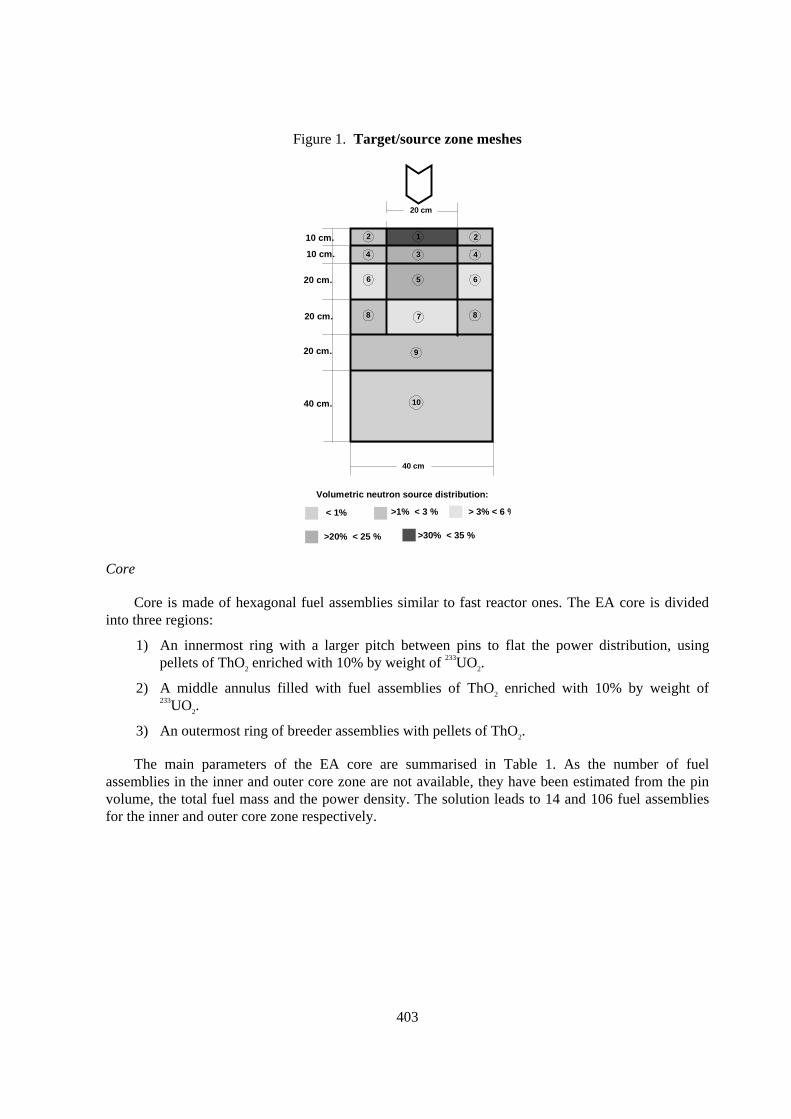
The target and buffer have an external radius [2] of 40 cm. The target/source region, of 20 cm indiameter and 1.2 m in high, was modelled (Figure 1) with cylindrical meshes according to a previouscalculation [7] performed with LAHET [8] code.
The MCNP neutron source distribution is derived from LAHET calculation performed withproton energy of 1 GeV and neutron energy cut-off of 20 MeV. These calculations showed an almostisotropic angular distribution and substantial spatial independence of the energy spectra. The neutronsource was described in terms of volumetric distributions in the target meshes and energy spectrumfor whole target.
403
Figure 1. Target/source zone meshes
10 cm.
10 cm.
20 cm.
20 cm.
20 cm.
40 cm.
Volumetric neutron source distribution:
>20% < 25 %
< 1%
>30% < 35 %
>1% < 3 % > 3% < 6 %
2
4
6
8
2
4
6
8
1
3
5
7
9
10
20 cm
40 cm
Core
Core is made of hexagonal fuel assemblies similar to fast reactor ones. The EA core is dividedinto three regions:
1) An innermost ring with a larger pitch between pins to flat the power distribution, usingpellets of ThO2 enriched with 10% by weight of 233UO2.
2) A middle annulus filled with fuel assemblies of ThO2 enriched with 10% by weight of233UO2.
3) An outermost ring of breeder assemblies with pellets of ThO2.
The main parameters of the EA core are summarised in Table 1. As the number of fuelassemblies in the inner and outer core zone are not available, they have been estimated from the pinvolume, the total fuel mass and the power density. The solution leads to 14 and 106 fuel assembliesfor the inner and outer core zone respectively.
404
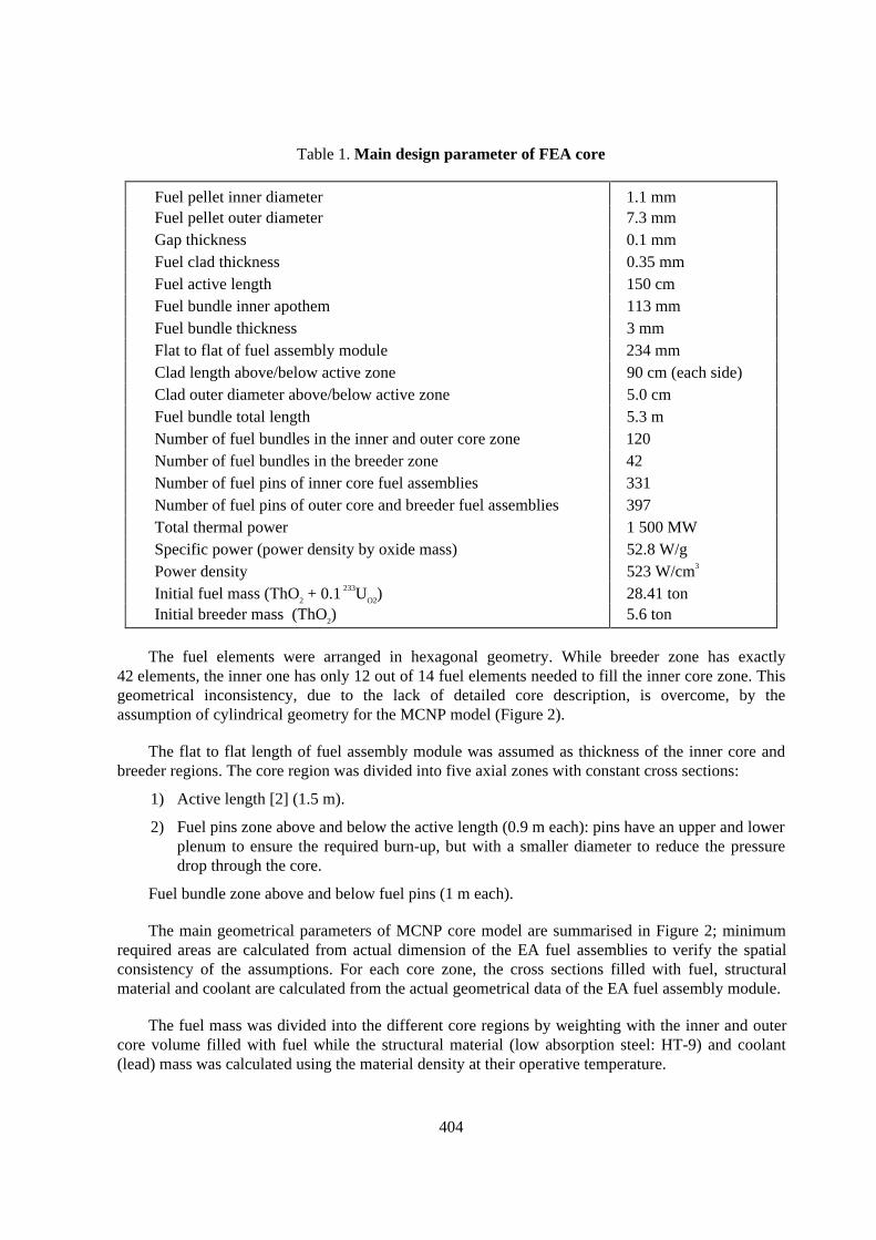
Table 1. Main design parameter of FEA core
Fuel pellet inner diameter 1.1 mmFuel pellet outer diameter 7.3 mmGap thickness 0.1 mmFuel clad thickness 0.35 mmFuel active length 150 cmFuel bundle inner apothem 113 mmFuel bundle thickness 3 mmFlat to flat of fuel assembly module 234 mmClad length above/below active zone 90 cm (each side)Clad outer diameter above/below active zone 5.0 cmFuel bundle total length 5.3 mNumber of fuel bundles in the inner and outer core zone 120Number of fuel bundles in the breeder zone 42Number of fuel pins of inner core fuel assemblies 331Number of fuel pins of outer core and breeder fuel assemblies 397Total thermal power 1 500 MWSpecific power (power density by oxide mass) 52.8 W/gPower density 523 W/cm3
Initial fuel mass (ThO2 + 0.1 233UO2) 28.41 tonInitial breeder mass (ThO2) 5.6 ton
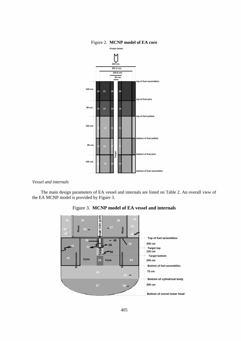
The fuel elements were arranged in hexagonal geometry. While breeder zone has exactly42 elements, the inner one has only 12 out of 14 fuel elements needed to fill the inner core zone. Thisgeometrical inconsistency, due to the lack of detailed core description, is overcome, by theassumption of cylindrical geometry for the MCNP model (Figure 2).
The flat to flat length of fuel assembly module was assumed as thickness of the inner core andbreeder regions. The core region was divided into five axial zones with constant cross sections:
1) Active length [2] (1.5 m).
2) Fuel pins zone above and below the active length (0.9 m each): pins have an upper and lowerplenum to ensure the required burn-up, but with a smaller diameter to reduce the pressuredrop through the core.
Fuel bundle zone above and below fuel pins (1 m each).
The main geometrical parameters of MCNP core model are summarised in Figure 2; minimumrequired areas are calculated from actual dimension of the EA fuel assemblies to verify the spatialconsistency of the assumptions. For each core zone, the cross sections filled with fuel, structuralmaterial and coolant are calculated from the actual geometrical data of the EA fuel assembly module.
The fuel mass was divided into the different core regions by weighting with the inner and outercore volume filled with fuel while the structural material (low absorption steel: HT-9) and coolant(lead) mass was calculated using the material density at their operative temperature.
405
Figure 2. MCNP model of EA core
334 cm.
287.2 cm.
126.8 cm.
40 cm.
100 cm.
100 cm.
90 cm.
90 cm.
150 cm.
20 202122
14 141516
11 111213
17 171819
23 232425
Tar
get
Proton beam
bottom of fuel pellets
bottom of fuel assemblies
bottom of fuel pins
top of fuel pellets
top of fuel pins
top of fuel assemblies
Vessel and internals
The main design parameters of EA vessel and internals are listed on Table 2. An overall view ofthe EA MCNP model is provided by Figure 3.
Figure 3. MCNP model of EA vessel and internals
205 cm
120 cm
205 cm
75 cm
300 cm
Bottom of cylindrical body
Bottom of fuel assemblies
Top of fuel assemblies
Target top
Target bottomCore
Tar
get31
30
45
35
34
28
36
43
44
Ris
er
Ris
erD
ow
nco
mer
Do
wn
com
er
Bea
m t
ub
e g
uid
e
Bottom of vessel lower head
41
27
42
38
37
28
33
46
45
32
43
40
29
39
Core26
406
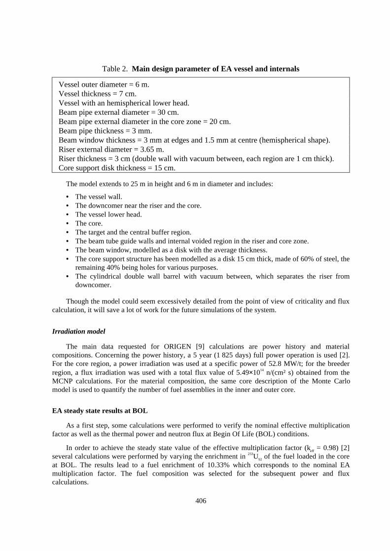
Table 2. Main design parameter of EA vessel and internals
Vessel outer diameter = 6 m.Vessel thickness = 7 cm.Vessel with an hemispherical lower head.Beam pipe external diameter = 30 cm.Beam pipe external diameter in the core zone = 20 cm.Beam pipe thickness = 3 mm.Beam window thickness = 3 mm at edges and 1.5 mm at centre (hemispherical shape).Riser external diameter = 3.65 m.Riser thickness = 3 cm (double wall with vacuum between, each region are 1 cm thick).Core support disk thickness = 15 cm.
The model extends to 25 m in height and 6 m in diameter and includes:
• The vessel wall.• The downcomer near the riser and the core.• The vessel lower head.• The core.• The target and the central buffer region.• The beam tube guide walls and internal voided region in the riser and core zone.• The beam window, modelled as a disk with the average thickness.• The core support structure has been modelled as a disk 15 cm thick, made of 60% of steel, the
remaining 40% being holes for various purposes.• The cylindrical double wall barrel with vacuum between, which separates the riser from
downcomer.
Though the model could seem excessively detailed from the point of view of criticality and fluxcalculation, it will save a lot of work for the future simulations of the system.
Irradiation model
The main data requested for ORIGEN [9] calculations are power history and materialcompositions. Concerning the power history, a 5 year (1 825 days) full power operation is used [2].For the core region, a power irradiation was used at a specific power of 52.8 MW/t; for the breederregion, a flux irradiation was used with a total flux value of 5.49×10¹⁴ n/(cm² s) obtained from theMCNP calculations. For the material composition, the same core description of the Monte Carlomodel is used to quantify the number of fuel assemblies in the inner and outer core.
EA steady state results at BOL
As a first step, some calculations were performed to verify the nominal effective multiplicationfactor as well as the thermal power and neutron flux at Begin Of Life (BOL) conditions.
In order to achieve the steady state value of the effective multiplication factor (keff = 0.98) [2]several calculations were performed by varying the enrichment in 233U92 of the fuel loaded in the coreat BOL. The results lead to a fuel enrichment of 10.33% which corresponds to the nominal EAmultiplication factor. The fuel composition was selected for the subsequent power and fluxcalculations.

407
Table 3 lists the results for the flux and power calculations for each region and whole systems.
The energy released per fission in 233U calculated by MCNP code is 180.84 MeV while,considering all contributions to the recoverable energy (kinetic energy of fission fragments andfission neutrons, β and γ rays from fission product decay, prompt γ rays and γ rays from capture ofstructural material) we have an energy ranging from 194 to 203 MeV/fission (depending upon thestructural material in the reactor) [13].
Taking into account the above considerations and the beam heat depositions in lead and window(7.07 MW) [2], the total FEA power is estimated to range from 1 347 to 1 409 MWth which is inreasonable agreement with the nominal power of 1 500 MWth. The standard deviation of the MonteCarlo calculations is 6.18% (from 83 to 87 MW) and many uncertainties already exists for thespallation neutron yield.
Table 3. Fast energy amplifier steady-state calculation at BOL
Region Neutron flux[n/(cm2 s)]
Flux σ (%) Fission promptpower (MW)
Fission power σ(%)
Inner Core 3.42049×10¹⁵ 2.44 201.08 3.51
Outer Core 2.03134×10¹⁵ 2.87 1,047.10 4.08
Inner and outercore average
2.20805×10¹⁵ 3.77
Breeder 5.63569×10¹⁴ 2.98 0.60 3.03
Core and breederaverage 1.75340×10¹⁵ 2.80 1,248.78 6.18
System effective multiplication factor (Keff) = 0.980022 (σ = 0.060 %).Spallation neutron yield = 26.5.Proton beam nominal current = 12.5 mA.
As regards the neutron flux, a direct comparison is not possible because its value is not explicitlyindicated in the FEA nominal parameters of chapter 4 of Reference 2. On the other hand, there is areasonable confidence that the calculated value is in good agreement with the FEA ones; in fact,Table 2.3 of chapter 2 in Reference 2 reports a neutron flux of 2.33 x 10¹⁵ n/(cm² s) for a powerdensity of 60 W/gTh at breeding equilibrium while the calculated (averaged inner and outer core)MCNP value is of 2.21 x 10¹⁵ for a power density of 52.8 W/gMOX at BOL.
Irradiation calculations
For the core region (inner and outer), the calculations were carried out considering a core powerof 1 500 MW with a specific power of 52.8 W/g of oxide for a 5 year cycle (1 825 Effective FullPower Days, EFPD). These data lead to a total mass of 28.409 t of oxide and to a burn-up of96 GWd/t compared to 28.41 t and 100 GWd/t of Reference 2. Using the cross section values for 232Thand 233U, a flux value of about 2.6×10¹⁵ n/(cm2 s) was estimated compared to an average neutron fluxvalue from ORIGEN ranging from about 2.43×10¹⁵ n/(cm2 s) to 2.49×10¹⁵ n/(cm2 s) according to theused library (from 2.52×10¹⁵ n/(cm2 s) to 2.56×10¹⁵ n/(cm2 s) in the first time step of 3 days) and ofabout 2.21×10¹⁵ n/(cm2 s) from the MCNP at BOL.
408
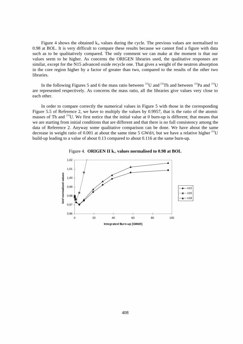
Figure 4 shows the obtained k∞ values during the cycle. The previous values are normalised to0.98 at BOL. It is very difficult to compare these results because we cannot find a figure with datasuch as to be qualitatively compared. The only comment we can make at the moment is that ourvalues seem to be higher. As concerns the ORIGEN libraries used, the qualitative responses aresimilar, except for the N15 advanced oxide recycle one. That gives a weight of the neutron absorptionin the core region higher by a factor of greater than two, compared to the results of the other twolibraries.
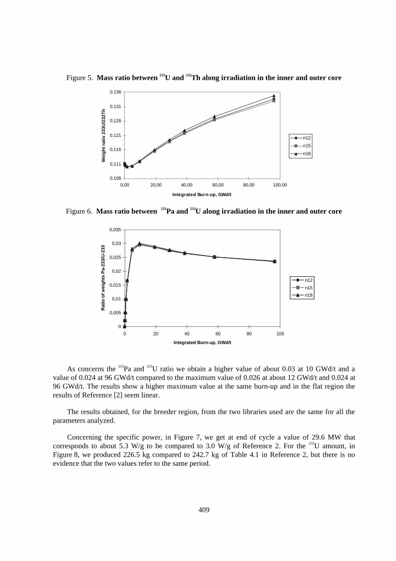
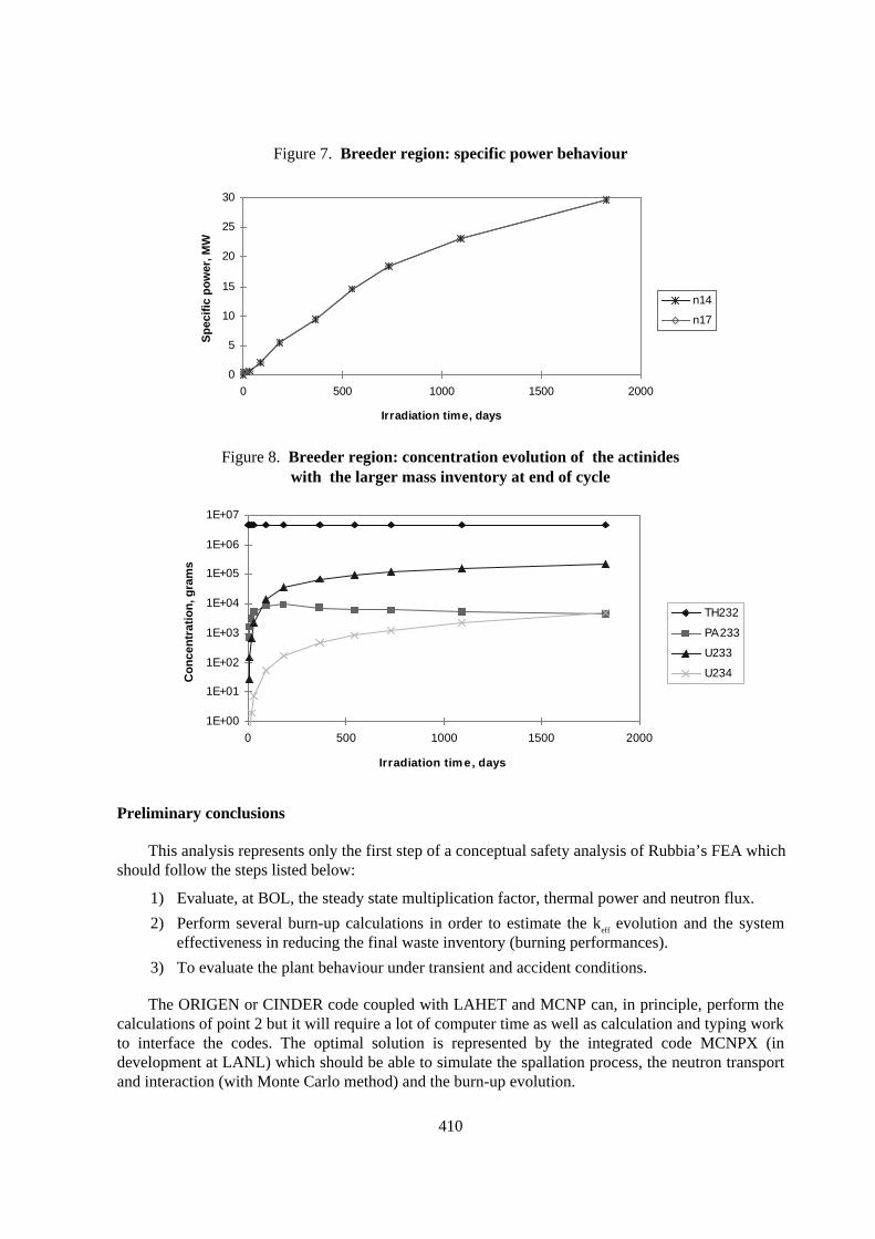
In the following Figures 5 and 6 the mass ratio between 233U and 232Th and between 233Pa and 233Uare represented respectively. As concerns the mass ratio, all the libraries give values very close toeach other.
In order to compare correctly the numerical values in Figure 5 with those in the correspondingFigure 5.5 of Reference 2, we have to multiply the values by 0.9957, that is the ratio of the atomicmasses of Th and 233U. We first notice that the initial value at 0 burn-up is different; that means thatwe are starting from initial conditions that are different and that there is no full consistency among thedata of Reference 2. Anyway some qualitative comparison can be done. We have about the samedecrease in weight ratio of 0.001 at about the same time 5 GWd/t, but we have a relative higher 233Ubuild-up leading to a value of about 0.13 compared to about 0.116 at the same burn-up.
Figure 4. ORIGEN II k∞ values normalised to 0.98 at BOL
0,96
0,97
0,98
0,99
1,00
1,01
1,02
0 20 40 60 80 100
Integrated Burn-up [GWd/t]
kin
f n
orm
aliz
ed v
alu
es
n12
n15
n18
409
Figure 5. Mass ratio between 233U and 232Th along irradiation in the inner and outer core
0,106
0,111
0,116
0,121
0,126
0,131
0,136
0,00 20,00 40,00 60,00 80,00 100,00
Integrated Burn-up, GWd/t
Wei
gh
t ra
tio
233
U/2
32T
h
n12
n15
n18
Figure 6. Mass ratio between 233Pa and 233U along irradiation in the inner and outer core
0
0,005
0,01
0,015
0,02
0,025
0,03
0,035
0 20 40 60 80 100
Integrated Burn-up, GWd/t
Rat
io o
f w
eig
hts
Pa-
233/
U-2
33
n12
n15
n18
As concerns the 233Pa and 233U ratio we obtain a higher value of about 0.03 at 10 GWd/t and avalue of 0.024 at 96 GWd/t compared to the maximum value of 0.026 at about 12 GWd/t and 0.024 at96 GWd/t. The results show a higher maximum value at the same burn-up and in the flat region theresults of Reference [2] seem linear.
The results obtained, for the breeder region, from the two libraries used are the same for all theparameters analyzed.
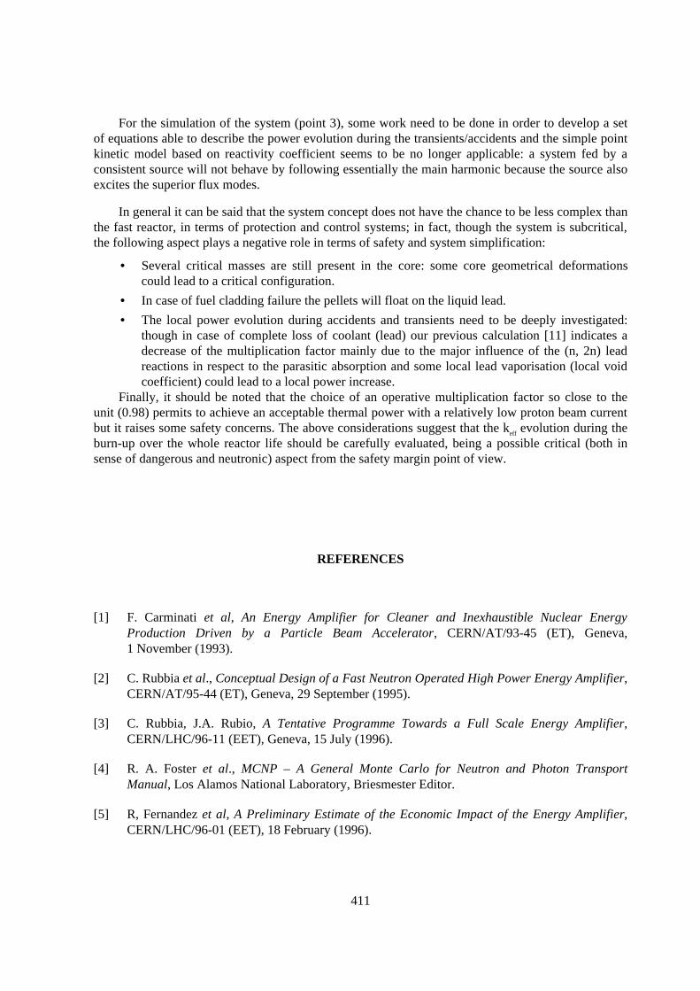
Concerning the specific power, in Figure 7, we get at end of cycle a value of 29.6 MW thatcorresponds to about 5.3 W/g to be compared to 3.0 W/g of Reference 2. For the 233U amount, inFigure 8, we produced 226.5 kg compared to 242.7 kg of Table 4.1 in Reference 2, but there is noevidence that the two values refer to the same period.
410
Figure 7. Breeder region: specific power behaviour
0
5
10
15
20
25
30
0 500 1000 1500 2000
Irradiation time, days
Sp
ecif
ic p
ow
er, M
W
n14
n17
Figure 8. Breeder region: concentration evolution of the actinideswith the larger mass inventory at end of cycle
1E+00
1E+01
1E+02
1E+03
1E+04
1E+05
1E+06
1E+07
0 500 1000 1500 2000
Irradiation time, days
Co
nce
ntr
atio
n, g
ram
s
TH232
PA233
U233
U234
Preliminary conclusions
This analysis represents only the first step of a conceptual safety analysis of Rubbia’s FEA whichshould follow the steps listed below:
1) Evaluate, at BOL, the steady state multiplication factor, thermal power and neutron flux.
2) Perform several burn-up calculations in order to estimate the keff evolution and the systemeffectiveness in reducing the final waste inventory (burning performances).
3) To evaluate the plant behaviour under transient and accident conditions.
The ORIGEN or CINDER code coupled with LAHET and MCNP can, in principle, perform thecalculations of point 2 but it will require a lot of computer time as well as calculation and typing workto interface the codes. The optimal solution is represented by the integrated code MCNPX (indevelopment at LANL) which should be able to simulate the spallation process, the neutron transportand interaction (with Monte Carlo method) and the burn-up evolution.
411
For the simulation of the system (point 3), some work need to be done in order to develop a setof equations able to describe the power evolution during the transients/accidents and the simple pointkinetic model based on reactivity coefficient seems to be no longer applicable: a system fed by aconsistent source will not behave by following essentially the main harmonic because the source alsoexcites the superior flux modes.
In general it can be said that the system concept does not have the chance to be less complex thanthe fast reactor, in terms of protection and control systems; in fact, though the system is subcritical,the following aspect plays a negative role in terms of safety and system simplification:
• Several critical masses are still present in the core: some core geometrical deformationscould lead to a critical configuration.
• In case of fuel cladding failure the pellets will float on the liquid lead.
• The local power evolution during accidents and transients need to be deeply investigated:though in case of complete loss of coolant (lead) our previous calculation [11] indicates adecrease of the multiplication factor mainly due to the major influence of the (n, 2n) leadreactions in respect to the parasitic absorption and some local lead vaporisation (local voidcoefficient) could lead to a local power increase.
Finally, it should be noted that the choice of an operative multiplication factor so close to theunit (0.98) permits to achieve an acceptable thermal power with a relatively low proton beam currentbut it raises some safety concerns. The above considerations suggest that the keff evolution during theburn-up over the whole reactor life should be carefully evaluated, being a possible critical (both insense of dangerous and neutronic) aspect from the safety margin point of view.
REFERENCES
[1] F. Carminati et al, An Energy Amplifier for Cleaner and Inexhaustible Nuclear EnergyProduction Driven by a Particle Beam Accelerator, CERN/AT/93-45 (ET), Geneva,1 November (1993).
[2] C. Rubbia et al., Conceptual Design of a Fast Neutron Operated High Power Energy Amplifier,CERN/AT/95-44 (ET), Geneva, 29 September (1995).
[3] C. Rubbia, J.A. Rubio, A Tentative Programme Towards a Full Scale Energy Amplifier,CERN/LHC/96-11 (EET), Geneva, 15 July (1996).
[4] R. A. Foster et al., MCNP – A General Monte Carlo for Neutron and Photon TransportManual, Los Alamos National Laboratory, Briesmester Editor.
[5] R, Fernandez et al, A Preliminary Estimate of the Economic Impact of the Energy Amplifier,CERN/LHC/96-01 (EET), 18 February (1996).
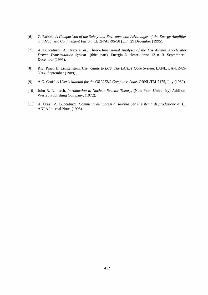
412
[6] C. Rubbia, A Comparison of the Safety and Environmental Advantages of the Energy Amplifierand Magnetic Confinement Fusion, CERN/AT/95-58 (ET). 29 December (1995).
[7] A. Buccafurni, A. Orazi et al., Three-Dimensional Analysis of the Los Alamos AcceleratorDriven Transmutation System – (third part), Energia Nucleare, anno 12 n. 3. September –December (1995).
[8] R.E. Prael, H. Lichtenstein, User Guide to LCS: The LAHET Code System, LANL, LA-UR-89-3014, September (1989).
[9] A.G. Croff, A User’s Manual for the ORIGEN2 Computer Code, ORNL/TM-7175, July (1980).
[10] John R. Lamarsh, Introduction to Nuclear Reactor Theory, (New York University) Addison-Wesley Publishing Company, (1972).
[11] A. Orazi, A. Buccafurni, Commenti all’ipotesi di Rubbia per il sistema di produzione di H2,ANPA Internal Note, (1995).
413
PERFORMANCE ON ACTINIDE TRANSMUTATION OF LEAD-THORIUM BASED ADS
R. Fernández, M. Embid, J. García-Sanz, E. GonzálezFACET group. CIEMAT.
Av. Complutense 22, Madrid 28040Spain
Abstract
The FACET group at CIEMAT is studying the properties and potentialities of several lead-cooledADS designs for actinide and fission product transmutation. The main characteristics of these systemsare the use of lead as primary coolant and moderator and fuels made by transuranics inside a thoriumoxide matrix.
The aim of the study is to analyse the effect of some operation parameters (fuel transuranicscomposition, thermal power and transuranics recycling scheme) in the ADS performance, mainly inthe achieved transmutation rates and in the accelerator requirements.
The model selected enhances the energy production by the 233U breeding from thorium seed. Thisbreeding can maintain the neutron multiplication during long burnups, improving the transmutationcapacity. The fuel inventory isotopic evolution during burnup will be presented illustrating thegeneral capabilities of this strategic option for transuranics transmutation.
414
Introduction
One of the major problems of nuclear power production is the undesired long-lived radioactivewaste that comes from the spent fuel used for electricity production. Currently many countries plan todeal with these products storing them into geological repositories. However, in the recent years anincreasing attention is paid to the transmutation option as a complementary activity to geologicaldisposal in a near future [1]. Among the foreseen advantages of transmutation are a reduction involume of the high level waste and a reduction in the long-term radiotoxicity inventory, with animpact in reducing the final costs and potential risks of the geological repository.
The transmutation of radioactive waste could be applied to two main groups of nuclides, eachgroup with its own elimination methods and different impact in the waste management strategy:
− The transuranics (TRUs) mainly neptunium, plutonium, americium and curium isotopescoming from the LWR’s discharge. They are responsible of the long-term radiotoxicity andtheir elimination should be done by fission since every neutron capture just increases themass number of the considered actinide. Any optimised TRUs transmutation strategy has toreach the highest fission to capture ratios, something not easy to achieve in the case of thefissile under threshold TRUs, and take into account the energy production duringtransmutation process.
− The fission products (FP), some of them with a very large radiotoxical potential in the shortor even in the long term. Their elimination means to transform them by neutron capture andsubsequent radioactive decay into stable isotopes, something that has some extra energy cost.
The impact of the transmutation in the waste management policy of each country will depend onthe size of the local nuclear power industry and the characteristics of the current and foreseen nuclearfuel cycle, among others. An optimal use of nuclear waste transmutation is unavoidable connected tothe development of partitioning methods due to the necessity to separate waste streams: TRUs and FPfrom the spent fuel uranium matrix. Currently, nuclear fuel reprocessing is available only in a fewcountries in the world. In addition, some countries assume that plutonium is another nuclear fuelinstead of as waste, and burn it with the MOX fuel technologies. To them, the TRUs eliminationmeans neptunium, americium and curium elimination in specially design systems, with differentproperties compared to the TRU-with plutonium charged ADS.
Due to the diverse points of view about transmutation, there is a wide scope of R&D strategiesthat has produced a large amount of proposed policies and systems for nuclear waste transmutationthat could be available in the near future. However, in the last decade the Accelerator Driven Systems(ADS) appear among the most promising transmutation systems. Basically the common componentsof every ADS are:
− A subcritical core (k<1), loaded with the unwanted TRUs and (maybe) FP to eliminate.
− A proton accelerator, producing a beam of some mA of intensity and an energy of a fewhundreds of MeV. This beam produces the spallation neutron source that the subcritical coreneed in order to maintain its operation regime.
The subcritical core configuration of the ADS would allow burning up some atypical actinidemixtures for long irradiation periods; with this kind of systems it is not necessary to reach somereactivity excess in order to start the operation, because the external source maintain the steady state.
415
The Energy Amplifier Model of Lead-thorium Based ADS
The ADS model considered in the present study is the so-called Energy Amplifier (EA), aconcept developed at CERN by Prof. C. Rubbia’s research group [2].
Basically an EA is an ADS cooled by molten lead, material that also works as spallation targetand neutron diffusing medium. Because of the special neutronics properties of lead, the neutronregime is fast (an energy spectrum centred on a few hundreds of keV). The fast EA design is, inprinciple, very adequate for elimination of those TRUs non-fissile under thermal spectra (seediscussion in refs. [2]). The EA concept is very flexible permitting:
− A neutron multiplication constant (keff) that could vary between 0.93 and 0.98. The chose ofkeff value has an important impact on accelerator requirements.
− Both metal and oxide fuel has been proposed, depending the final selection on the powerdensity limits and the working temperatures. Typically in the EA core, the TRUs charge totransmute is mixed into a thorium matrix. The presence of thorium allows the system tomaintain the neutron multiplication: the fissile TRUs burning can be compensated by the232Th to 233U breeding, followed by 233U fission.
− A wide range of operating conditions, with different thermal power (a few MW up to 1500 MW) or (equivalently) proton beam conditions (300 MeV to a few GeV of energy),depending on the model considered. The operating conditions will play an important role inthe transmutation efficiency.
− Options under study have been presented by Rubbia’s team [2] for FP incineration,distributing them in the lead diffusive media outside the EA core.
The simulations performed in this study have been focused primarily in the effects of the initialTRUs inventory composition, the thermal power and the proton beam energy on the performance ofthe system. The table 1 summarised the main parameters of the models under study. Two thermalenergy outputs have been considered: 200 MW, which corresponds to a large-size demo EA facility,and a medium-size energy production unit of 800 MW. For simulation purposes, it has been supposedthat the increase in thermal power is gained not directly by beam intensity increase but by protonkinetic energy growth, therefore going from 200 MWth to 800 MWth would imply a proton energy risefrom 380 MeV to 1 GeV.
The study on the nuclear fuel composition effect on the EA performance has been done for threeselected TRU mixtures. These mixtures have been calculated with ORIGEN2.1 [3] (table 2)modelling a typical PWR discharge. The differences are due to the cooling down time, considered asthe delay time between the PWR discharge and the EA load (10, 25 and 40 years). The hypothesis isthat the PWR discharge reprocessing produces a transuranics stream without any specific elementseparation inside it. This means that neptunium, plutonium, americium and curium are extracted inalmost the same relative percentage they have in the spend fuel.
Basically, increasing the cooling down time produces an increase in the 241Am concentration by241Pu decay. This conversion will have an important effect in neutronic properties evolution of the EAbecause while the 241Pu is a fissile actinide, the 241Am is fertile (by neutron capture it produces someamount of high fissile 242*Am). There is also a slight decrease of the 238Pu concentration while otherplutonium isotopes (239Pu, 240Pu and 242Pu) remain near to constant. Among the curium isotopes anotherrapid decayed isotope is the 244Cm.
416
Table 1 EA Models simulated
Number 1 2 3 4Thermal output (MW) 200 800 800 800Proton energy (MeV) 380 1000 1000 1000Fuel composition (TRUs+Th)O2
TRU mixture cooling down time (years) 40 40 25 10Fuel oxide mass (kg) ∼10 tonTRUs/Th ∼0.32 ∼0.32 ∼0.35 ∼0.38(Th+TRUs)/Pb mass fraction (core) ∼0.20 ∼0.20 ∼0.20 ∼0.20Cladding material HT9 steel
All the simulated EA models share the geometry characteristics (table 3). The geometry modelsused during simulation are:
− A complete detailed description of the EA core, where each single fuel pin of every fuelbundles, including its own cladding and the bundle wall, can be distinguish.
− A homogenous model, where the internal structure of a fuel bundle is homogenised to amixture of materials, preserving the total mass and every isotope mass fraction during theconversion (figure 1).
The differences in the Monte-Carlo estimators when using heterogeneous or homogeneousdescriptions of the EA has been discussed elsewhere [4].
Table 2 TRU mixtures mass fractions considered in the simulation
Cooling down time 10 years 25 years 40 years
237Np 5.31E-02 5.51E-02 5.78E-02239Np 0.00E+00 0.00E+00 0.00E+00236Pu 1.35E-08 3.57E-10 0.00E+00238Pu 1.71E-02 1.52E-02 1.35E-02239Pu 5.15E-01 5.16E-01 5.17E-01240Pu 2.13E-01 2.14E-01 2.15E-01241Pu 8.39E-02 4.08E-02 1.99E-02242Pu 4.96E-02 4.98E-02 4.99E-02241Am 5.65E-02 9.80E-02 1.17E-01242*Am 9.77E-05 9.10E-05 8.56E-05243Am 9.82E-03 9.83E-03 9.84E-03242Cm 2.55E-07 2.37E-07 2.07E-07243Cm 3.83E-05 2.68E-05 1.84E-05244Cm 2.04E-03 1.15E-03 6.52E-04245Cm 1.22E-04 1.22E-04 1.22E-04246Cm 1.38E-05 1.38E-05 1.38E-05247Cm 1.37E-07 1.37E-07 1.38E-07
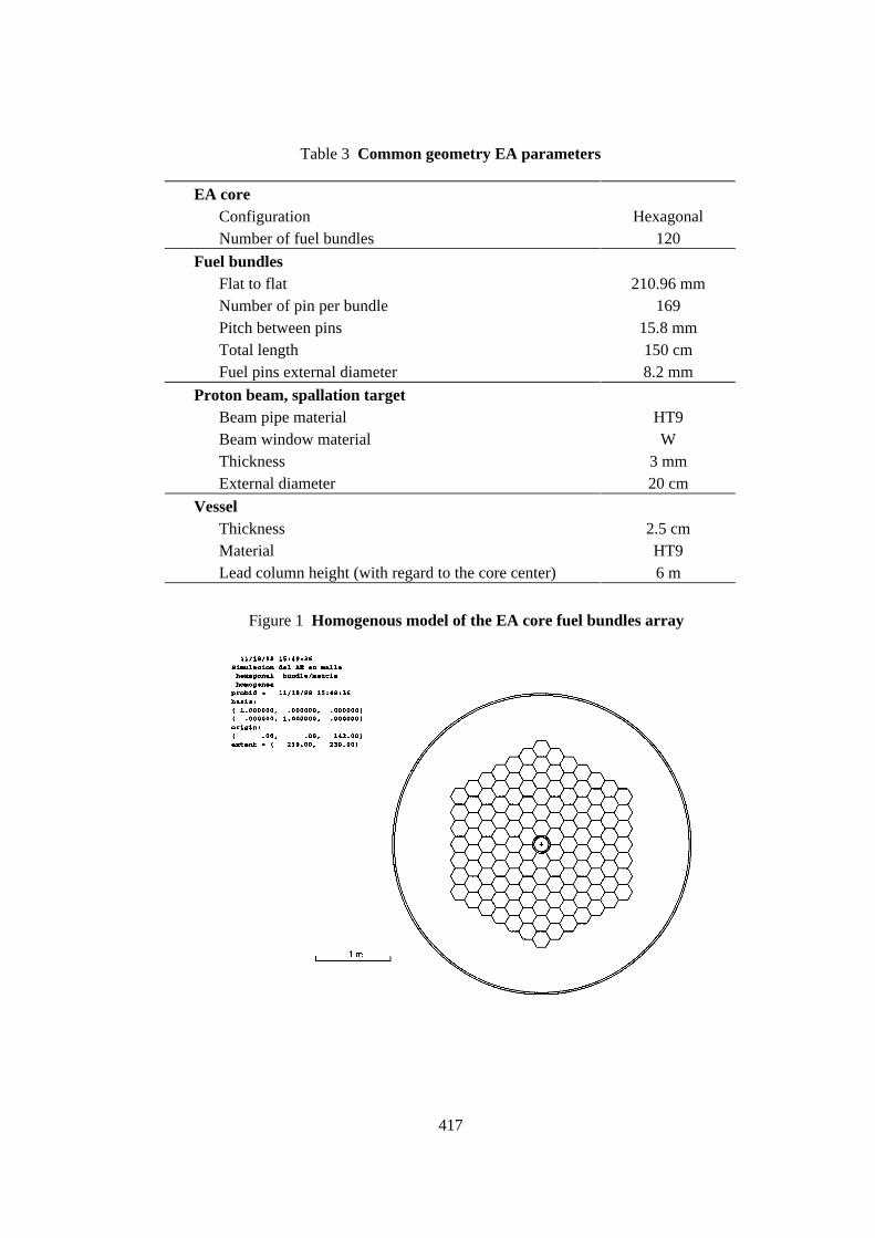
417
Table 3 Common geometry EA parameters
EA coreConfiguration HexagonalNumber of fuel bundles 120
Fuel bundlesFlat to flat 210.96 mmNumber of pin per bundle 169Pitch between pins 15.8 mmTotal length 150 cmFuel pins external diameter 8.2 mm
Proton beam, spallation targetBeam pipe material HT9Beam window material WThickness 3 mmExternal diameter 20 cm
VesselThickness 2.5 cmMaterial HT9Lead column height (with regard to the core center) 6 m
Figure 1 Homogenous model of the EA core fuel bundles array
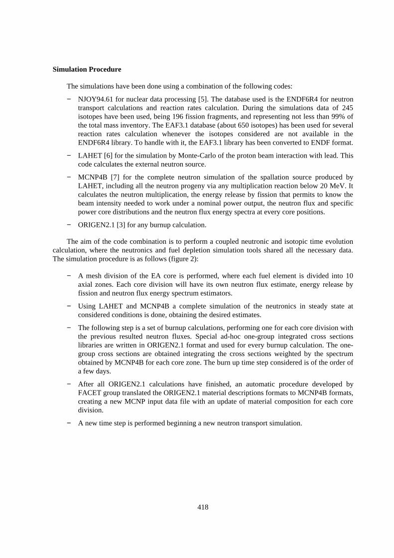
418
Simulation Procedure
The simulations have been done using a combination of the following codes:
− NJOY94.61 for nuclear data processing [5]. The database used is the ENDF6R4 for neutrontransport calculations and reaction rates calculation. During the simulations data of 245isotopes have been used, being 196 fission fragments, and representing not less than 99% ofthe total mass inventory. The EAF3.1 database (about 650 isotopes) has been used for severalreaction rates calculation whenever the isotopes considered are not available in theENDF6R4 library. To handle with it, the EAF3.1 library has been converted to ENDF format.
− LAHET [6] for the simulation by Monte-Carlo of the proton beam interaction with lead. Thiscode calculates the external neutron source.
− MCNP4B [7] for the complete neutron simulation of the spallation source produced byLAHET, including all the neutron progeny via any multiplication reaction below 20 MeV. Itcalculates the neutron multiplication, the energy release by fission that permits to know thebeam intensity needed to work under a nominal power output, the neutron flux and specificpower core distributions and the neutron flux energy spectra at every core positions.
− ORIGEN2.1 [3] for any burnup calculation.
The aim of the code combination is to perform a coupled neutronic and isotopic time evolutioncalculation, where the neutronics and fuel depletion simulation tools shared all the necessary data.The simulation procedure is as follows (figure 2):
− A mesh division of the EA core is performed, where each fuel element is divided into 10axial zones. Each core division will have its own neutron flux estimate, energy release byfission and neutron flux energy spectrum estimators.
− Using LAHET and MCNP4B a complete simulation of the neutronics in steady state atconsidered conditions is done, obtaining the desired estimates.
− The following step is a set of burnup calculations, performing one for each core division withthe previous resulted neutron fluxes. Special ad-hoc one-group integrated cross sectionslibraries are written in ORIGEN2.1 format and used for every burnup calculation. The one-group cross sections are obtained integrating the cross sections weighted by the spectrumobtained by MCNP4B for each core zone. The burn up time step considered is of the order ofa few days.
− After all ORIGEN2.1 calculations have finished, an automatic procedure developed byFACET group translated the ORIGEN2.1 material descriptions formats to MCNP4B formats,creating a new MCNP input data file with an update of material composition for each coredivision.
− A new time step is performed beginning a new neutron transport simulation.
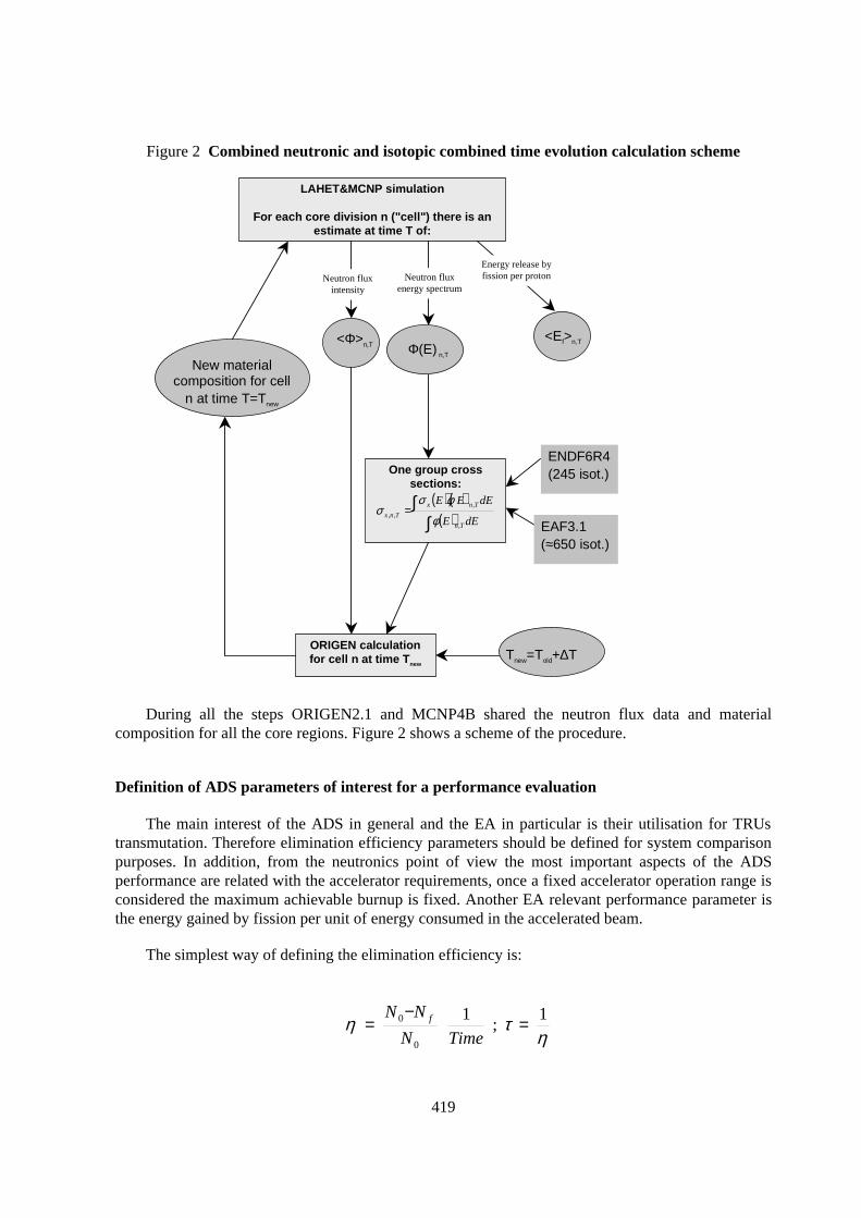
419
Figure 2 Combined neutronic and isotopic combined time evolution calculation scheme
LAHET&MCNP simulation
For each core division n ("cell") there is anestimate at time T of:
<Ef>n,T<Φ>n,T Φ(E) n,T
One group crosssections:
( ) ( )( )∫
∫=dEE
dEEE
Tn
Tnx
Tnx
,
,
,, φ
φσσ
ORIGEN calculationfor cell n at time Tnew
Tnew=Told+∆T
New materialcomposition for cell
n at time T=Tnew
ENDF6R4(245 isot.)
EAF3.1(≈650 isot.)
Neutron fluxintensity
Energy release byfission per protonNeutron flux
energy spectrum
During all the steps ORIGEN2.1 and MCNP4B shared the neutron flux data and materialcomposition for all the core regions. Figure 2 shows a scheme of the procedure.
Definition of ADS parameters of interest for a performance evaluation
The main interest of the ADS in general and the EA in particular is their utilisation for TRUstransmutation. Therefore elimination efficiency parameters should be defined for system comparisonpurposes. In addition, from the neutronics point of view the most important aspects of the ADSperformance are related with the accelerator requirements, once a fixed accelerator operation range isconsidered the maximum achievable burnup is fixed. Another EA relevant performance parameter isthe energy gained by fission per unit of energy consumed in the accelerated beam.
The simplest way of defining the elimination efficiency is:
ητη 1
;1
0
0 =−
=TimeN
NN f
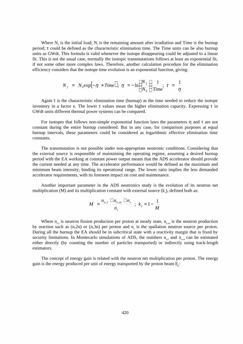
420
Where N0 is the initial load; Nf is the remaining amount after irradiation and Time is the burnupperiod; τ could be defined as the characteristic elimination time. The Time units can be also burnupunits as GWdt. This formula is valid whenever the isotope disappearing could be adjusted to a linearfit. This is not the usual case, normally the isotopic transmutations follows at least an exponential fit,if not some other more complex laws. Therefore, another calculation procedure for the eliminationefficiency considers that the isotope time evolution is an exponential function, giving:
Again τ is the characteristic elimination time (burnup) as the time needed to reduce the isotopeinventory in a factor e. The lower τ values mean the higher elimination capacity. Expressing τ inGWdt units different thermal power systems can be compared.
For isotopes that follows non-simple exponential function laws the parameters η and τ are notconstant during the entire burnup considered. But in any case, for comparison purposes at equalburnup intervals, these parameters could be considered as logarithmic effective elimination timeconstants.
The transmutation is not possible under non-appropriate neutronic conditions. Considering thatthe external source is responsible of maintaining the operating regime, assuming a desired burnupperiod with the EA working at constant power output means that the ADS accelerator should providethe current needed at any time. The accelerator performance would be defined as the maximum andminimum beam intensity, binding its operational range. The lower ratio implies the less demandedaccelerator requirements, with its foreseen impact on cost and maintenance.
Another important parameter in the ADS neutronics study is the evolution of its neutron netmultiplication (M) and its multiplication constant with external source (ks), defined both as:
Where nn,f is neutron fission production per proton at steady state, nn,xn is the neutron productionby reaction such as (n,2n) or (n,3n) per proton and ns is the spallation neutron source per proton.During all the burnup the EA should be in subcritical state with a reactivity margin that is fixed bysecurity limitations. In Montecarlo simulations of ADS, the numbers nn,f and nn,xn can be estimatedeither directly (by counting the number of particles transported) or indirectly using track-lengthestimators.
The concept of energy gain is related with the neutron net multiplication per proton. The energygain is the energy produced per unit of energy transported by the proton beam Ep:
( )η
τηη 1;
1ln;exp
00 =
−=×−=
TimeN
NTimeNN f
f
Mk
n
nnnM s
s
sxnnfn 11;,, −=
++=
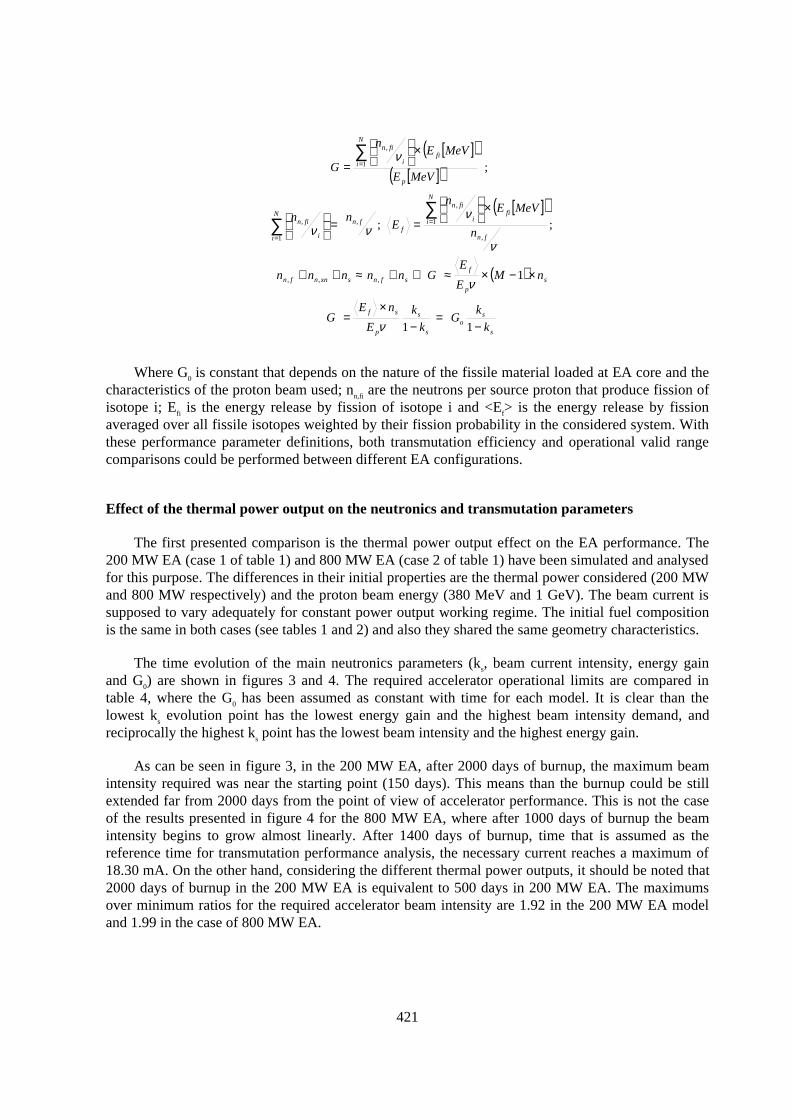
421
Where G0 is constant that depends on the nature of the fissile material loaded at EA core and thecharacteristics of the proton beam used; nn,fi are the neutrons per source proton that produce fission ofisotope i; Efi is the energy release by fission of isotope i and <Ef> is the energy release by fissionaveraged over all fissile isotopes weighted by their fission probability in the considered system. Withthese performance parameter definitions, both transmutation efficiency and operational valid rangecomparisons could be performed between different EA configurations.
Effect of the thermal power output on the neutronics and transmutation parameters
The first presented comparison is the thermal power output effect on the EA performance. The200 MW EA (case 1 of table 1) and 800 MW EA (case 2 of table 1) have been simulated and analysedfor this purpose. The differences in their initial properties are the thermal power considered (200 MWand 800 MW respectively) and the proton beam energy (380 MeV and 1 GeV). The beam current issupposed to vary adequately for constant power output working regime. The initial fuel compositionis the same in both cases (see tables 1 and 2) and also they shared the same geometry characteristics.
The time evolution of the main neutronics parameters (ks, beam current intensity, energy gainand G0) are shown in figures 3 and 4. The required accelerator operational limits are compared intable 4, where the G0 has been assumed as constant with time for each model. It is clear than thelowest ks evolution point has the lowest energy gain and the highest beam intensity demand, andreciprocally the highest ks point has the lowest beam intensity and the highest energy gain.
As can be seen in figure 3, in the 200 MW EA, after 2000 days of burnup, the maximum beamintensity required was near the starting point (150 days). This means than the burnup could be stillextended far from 2000 days from the point of view of accelerator performance. This is not the caseof the results presented in figure 4 for the 800 MW EA, where after 1000 days of burnup the beamintensity begins to grow almost linearly. After 1400 days of burnup, time that is assumed as thereference time for transmutation performance analysis, the necessary current reaches a maximum of18.30 mA. On the other hand, considering the different thermal power outputs, it should be noted that2000 days of burnup in the 200 MW EA is equivalent to 500 days in 200 MW EA. The maximumsover minimum ratios for the required accelerator beam intensity are 1.92 in the 200 MW EA modeland 1.99 in the case of 800 MW EA.
[ ]( )[ ]( )
[ ]( )
( )
s
so
s
s
p
sf
sp
f
sfnsxnnfn
fn
N
ifi
i
fin
ffn
N
i i
fin
p
N
ifi
i
fin
k
kG
k
k
E
nEG
nME
EGnnnnn
n
MeVEn
Enn
MeVE
MeVEn
G
−=
−×
=
×−×≈⇒+≈++
×
==
×
=
∑∑
∑
=
=
=
11
1
;;
;
,,,
,
1
,
,
1
,
1
,
ν
ν
ν
ννν
ν
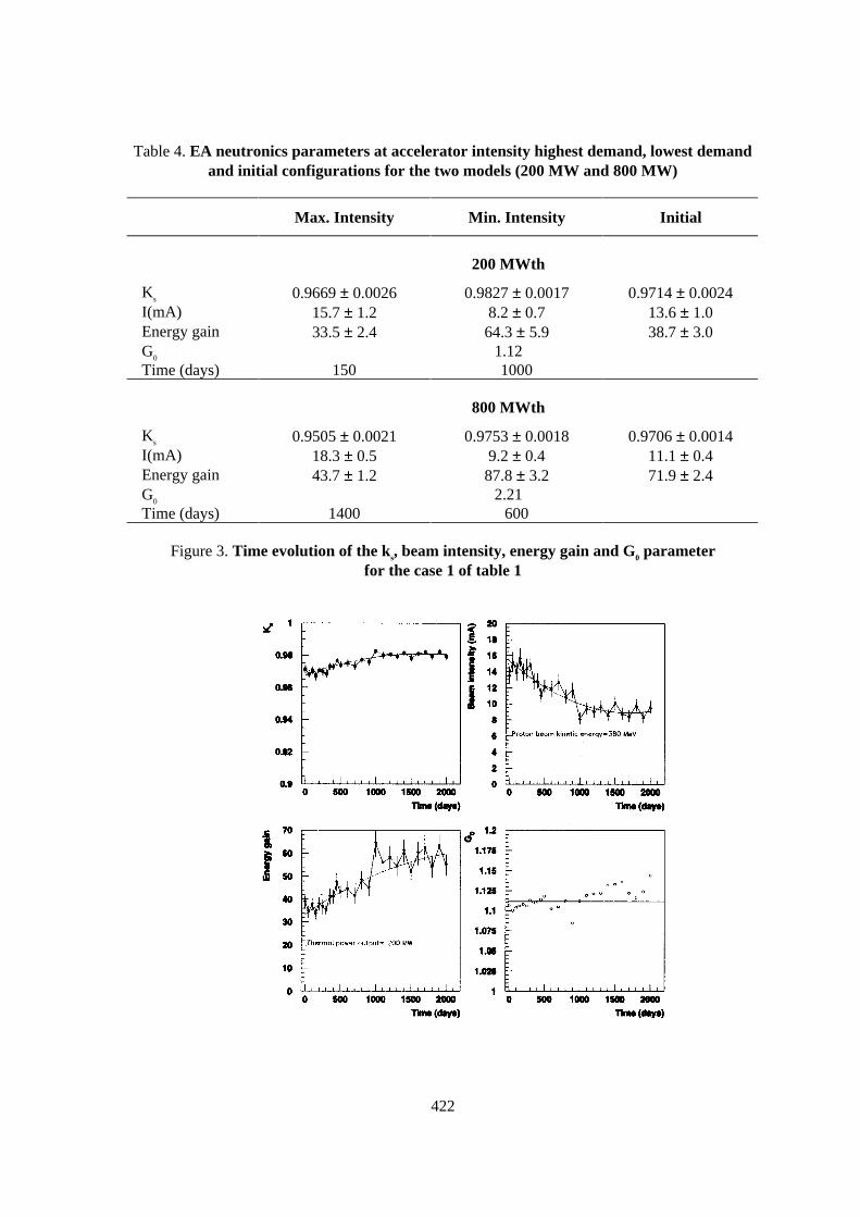
422
Table 4. EA neutronics parameters at accelerator intensity highest demand, lowest demandand initial configurations for the two models (200 MW and 800 MW)
Max. Intensity Min. Intensity Initial
200 MWth
Ks 0.9669 ± 0.0026 0.9827 ± 0.0017 0.9714 ± 0.0024I(mA) 15.7 ± 1.2 8.2 ± 0.7 13.6 ± 1.0Energy gain 33.5 ± 2.4 64.3 ± 5.9 38.7 ± 3.0G0 1.12Time (days) 150 1000
800 MWth
Ks 0.9505 ± 0.0021 0.9753 ± 0.0018 0.9706 ± 0.0014I(mA) 18.3 ± 0.5 9.2 ± 0.4 11.1 ± 0.4Energy gain 43.7 ± 1.2 87.8 ± 3.2 71.9 ± 2.4G0 2.21Time (days) 1400 600
Figure 3. Time evolution of the ks, beam intensity, energy gain and G0 parameterfor the case 1 of table 1
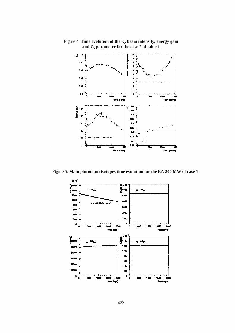
423
Figure 4 Time evolution of the ks, beam intensity, energy gainand G0 parameter for the case 2 of table 1
Figure 5. Main plutonium isotopes time evolution for the EA 200 MW of case 1
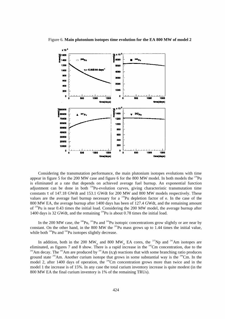
424
Figure 6. Main plutonium isotopes time evolution for the EA 800 MW of model 2
Considering the transmutation performance, the main plutonium isotopes evolutions with timeappear in figure 5 for the 200 MW case and figure 6 for the 800 MW model. In both models the 239Puis eliminated at a rate that depends on achieved average fuel burnup. An exponential functionadjustment can be done in both 239Pu-evolution curves, giving characteristic transmutation timeconstants τ of 147.18 GWdt and 153.1 GWdt for 200 MW and 800 MW models respectively. Thesevalues are the average fuel burnup necessary for a 239Pu depletion factor of e. In the case of the800 MW EA, the average burnup after 1400 days has been of 127.4 GWdt, and the remaining amountof 239Pu is near 0.43 times the initial load. Considering the 200 MW model, the average burnup after1400 days is 32 GWdt, and the remaining 239Pu is about 0.78 times the initial load.
In the 200 MW case, the 240Pu, 241Pu and 242Pu isotopic concentrations grow slightly or are near byconstant. On the other hand, in the 800 MW the 241Pu mass grows up to 1.44 times the initial value,while both 240Pu and 242Pu isotopes slightly decrease.
In addition, both in the 200 MWth and 800 MWth EA cores, the 237Np and 241Am isotopes areeliminated, as figures 7 and 8 show. There is a rapid increase in the 242Cm concentration, due to the242Am decay. The 242Am are produced by 241Am (n,γ) reactions that with some branching ratio producesground state 242Am. Another curium isotope that grows in some substantial way is the 244Cm. In themodel 2, after 1400 days of operation, the 244Cm concentration grows more than twice and in themodel 1 the increase is of 15%. In any case the total curium inventory increase is quite modest (in the800 MW EA the final curium inventory is 1% of the remaining TRUs).
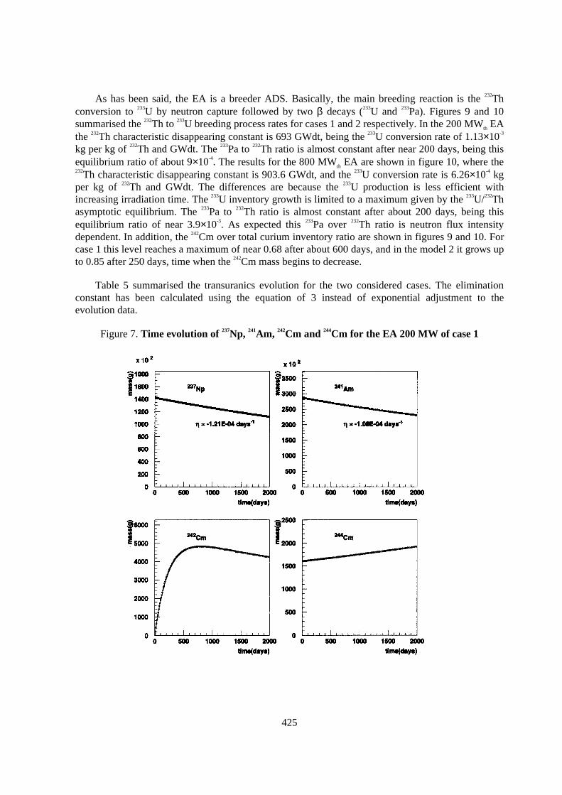
425
As has been said, the EA is a breeder ADS. Basically, the main breeding reaction is the 232Thconversion to 233U by neutron capture followed by two β decays (233U and 233Pa). Figures 9 and 10summarised the 232Th to 233U breeding process rates for cases 1 and 2 respectively. In the 200 MWth EAthe 232Th characteristic disappearing constant is 693 GWdt, being the 233U conversion rate of 1.13×10⁻³
kg per kg of 232Th and GWdt. The 233Pa to 232Th ratio is almost constant after near 200 days, being thisequilibrium ratio of about 9×10⁻⁴. The results for the 800 MWth EA are shown in figure 10, where the232Th characteristic disappearing constant is 903.6 GWdt, and the 233U conversion rate is 6.26×10⁻⁴ kgper kg of 232Th and GWdt. The differences are because the 233U production is less efficient withincreasing irradiation time. The 233U inventory growth is limited to a maximum given by the 233U/232Thasymptotic equilibrium. The 233Pa to 232Th ratio is almost constant after about 200 days, being thisequilibrium ratio of near 3.9×10⁻³. As expected this 233Pa over 232Th ratio is neutron flux intensitydependent. In addition, the 242Cm over total curium inventory ratio are shown in figures 9 and 10. Forcase 1 this level reaches a maximum of near 0.68 after about 600 days, and in the model 2 it grows upto 0.85 after 250 days, time when the 242Cm mass begins to decrease.
Table 5 summarised the transuranics evolution for the two considered cases. The eliminationconstant has been calculated using the equation of 3 instead of exponential adjustment to theevolution data.
Figure 7. Time evolution of 237Np, 241Am, 242Cm and 244Cm for the EA 200 MW of case 1
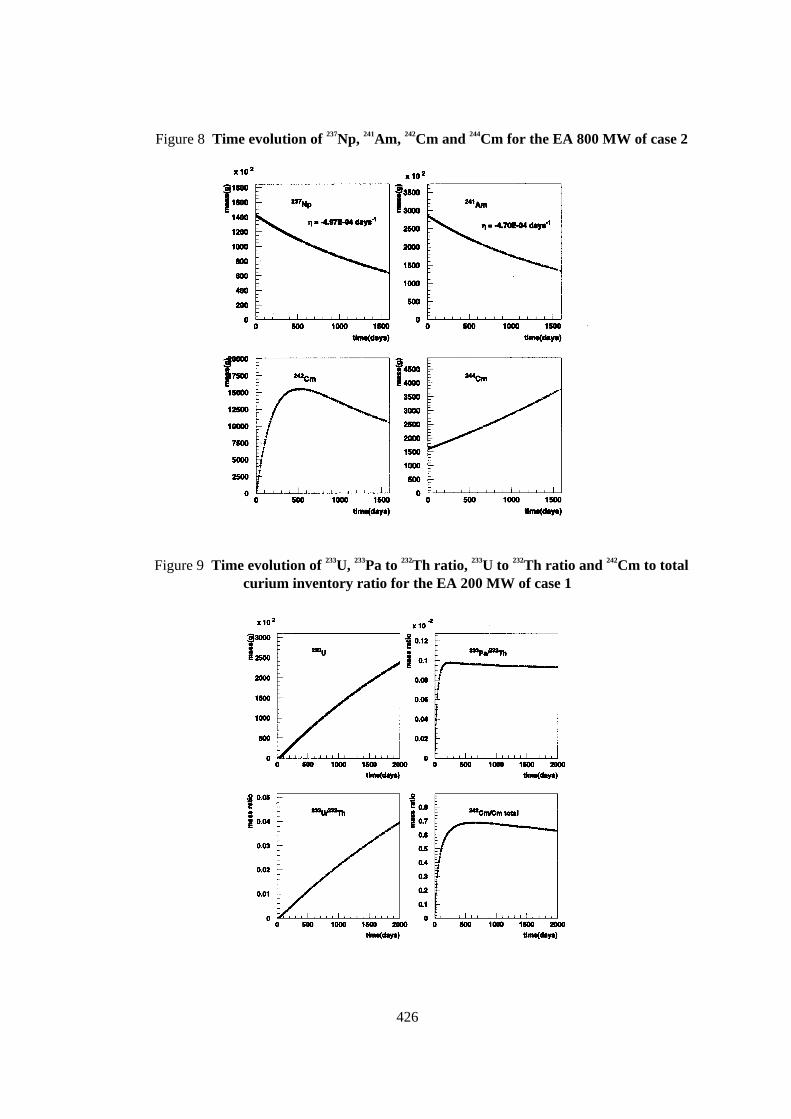
426
Figure 8 Time evolution of 237Np, 241Am, 242Cm and 244Cm for the EA 800 MW of case 2
Figure 9 Time evolution of 233U, 233Pa to 232Th ratio, 233U to 232Th ratio and 242Cm to totalcurium inventory ratio for the EA 200 MW of case 1
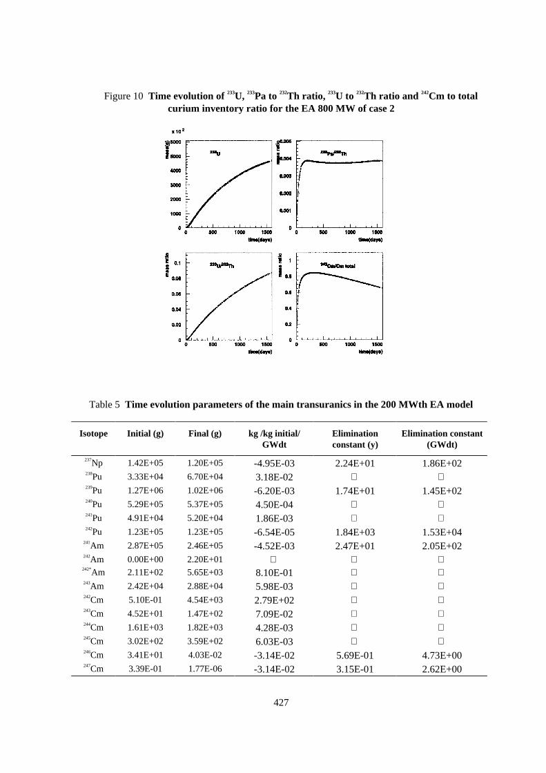
427
Figure 10 Time evolution of 233U, 233Pa to 232Th ratio, 233U to 232Th ratio and 242Cm to totalcurium inventory ratio for the EA 800 MW of case 2
Table 5 Time evolution parameters of the main transuranics in the 200 MWth EA model
Isotope Initial (g) Final (g) kg /kg initial/GWdt
Eliminationconstant (y)
Elimination constant(GWdt)
237Np 1.42E+05 1.20E+05 -4.95E-03 2.24E+01 1.86E+02238Pu 3.33E+04 6.70E+04 3.18E-02 239Pu 1.27E+06 1.02E+06 -6.20E-03 1.74E+01 1.45E+02240Pu 5.29E+05 5.37E+05 4.50E-04 241Pu 4.91E+04 5.20E+04 1.86E-03 242Pu 1.23E+05 1.23E+05 -6.54E-05 1.84E+03 1.53E+04
241Am 2.87E+05 2.46E+05 -4.52E-03 2.47E+01 2.05E+02242Am 0.00E+00 2.20E+01
242*Am 2.11E+02 5.65E+03 8.10E-01 243Am 2.42E+04 2.88E+04 5.98E-03 242Cm 5.10E-01 4.54E+03 2.79E+02 243Cm 4.52E+01 1.47E+02 7.09E-02 244Cm 1.61E+03 1.82E+03 4.28E-03 245Cm 3.02E+02 3.59E+02 6.03E-03 246Cm 3.41E+01 4.03E-02 -3.14E-02 5.69E-01 4.73E+00247Cm 3.39E-01 1.77E-06 -3.14E-02 3.15E-01 2.62E+00
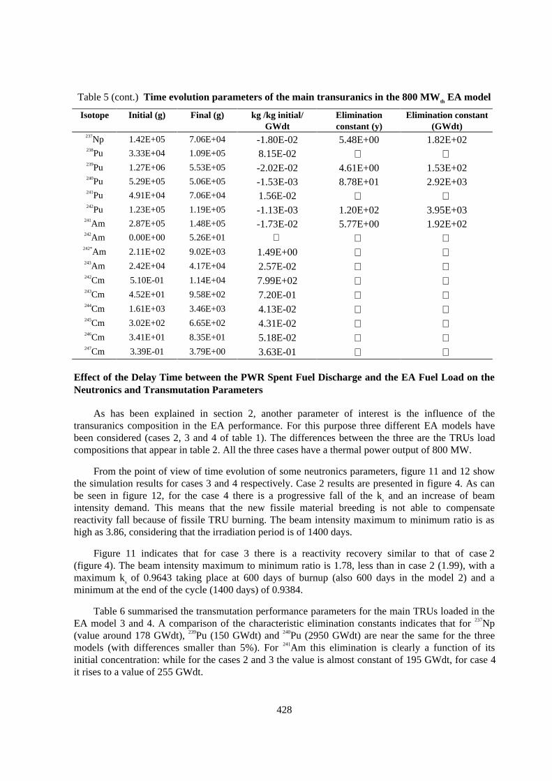
428
Table 5 (cont.) Time evolution parameters of the main transuranics in the 800 MWth EA model
Isotope Initial (g) Final (g) kg /kg initial/GWdt
Eliminationconstant (y)
Elimination constant(GWdt)
237Np 1.42E+05 7.06E+04 -1.80E-02 5.48E+00 1.82E+02238Pu 3.33E+04 1.09E+05 8.15E-02 239Pu 1.27E+06 5.53E+05 -2.02E-02 4.61E+00 1.53E+02240Pu 5.29E+05 5.06E+05 -1.53E-03 8.78E+01 2.92E+03241Pu 4.91E+04 7.06E+04 1.56E-02 242Pu 1.23E+05 1.19E+05 -1.13E-03 1.20E+02 3.95E+03
241Am 2.87E+05 1.48E+05 -1.73E-02 5.77E+00 1.92E+02242Am 0.00E+00 5.26E+01
242*Am 2.11E+02 9.02E+03 1.49E+00 243Am 2.42E+04 4.17E+04 2.57E-02 242Cm 5.10E-01 1.14E+04 7.99E+02 243Cm 4.52E+01 9.58E+02 7.20E-01 244Cm 1.61E+03 3.46E+03 4.13E-02 245Cm 3.02E+02 6.65E+02 4.31E-02 246Cm 3.41E+01 8.35E+01 5.18E-02 247Cm 3.39E-01 3.79E+00 3.63E-01
Effect of the Delay Time between the PWR Spent Fuel Discharge and the EA Fuel Load on theNeutronics and Transmutation Parameters
As has been explained in section 2, another parameter of interest is the influence of thetransuranics composition in the EA performance. For this purpose three different EA models havebeen considered (cases 2, 3 and 4 of table 1). The differences between the three are the TRUs loadcompositions that appear in table 2. All the three cases have a thermal power output of 800 MW.
From the point of view of time evolution of some neutronics parameters, figure 11 and 12 showthe simulation results for cases 3 and 4 respectively. Case 2 results are presented in figure 4. As canbe seen in figure 12, for the case 4 there is a progressive fall of the ks and an increase of beamintensity demand. This means that the new fissile material breeding is not able to compensatereactivity fall because of fissile TRU burning. The beam intensity maximum to minimum ratio is ashigh as 3.86, considering that the irradiation period is of 1400 days.
Figure 11 indicates that for case 3 there is a reactivity recovery similar to that of case 2(figure 4). The beam intensity maximum to minimum ratio is 1.78, less than in case 2 (1.99), with amaximum ks of 0.9643 taking place at 600 days of burnup (also 600 days in the model 2) and aminimum at the end of the cycle (1400 days) of 0.9384.
Table 6 summarised the transmutation performance parameters for the main TRUs loaded in theEA model 3 and 4. A comparison of the characteristic elimination constants indicates that for 237Np(value around 178 GWdt), 239Pu (150 GWdt) and 240Pu (2950 GWdt) are near the same for the threemodels (with differences smaller than 5%). For 241Am this elimination is clearly a function of itsinitial concentration: while for the cases 2 and 3 the value is almost constant of 195 GWdt, for case 4it rises to a value of 255 GWdt.
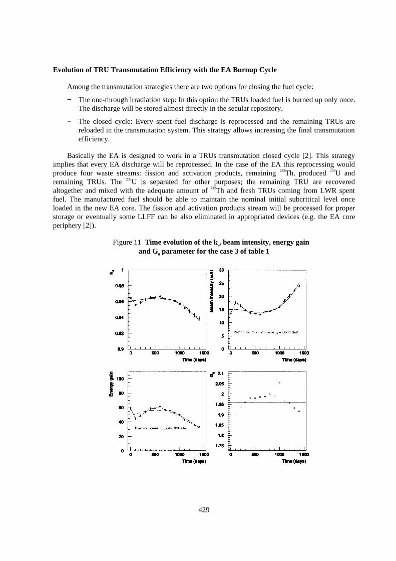
429
Evolution of TRU Transmutation Efficiency with the EA Burnup Cycle
Among the transmutation strategies there are two options for closing the fuel cycle:
− The one-through irradiation step: In this option the TRUs loaded fuel is burned up only once.The discharge will be stored almost directly in the secular repository.
− The closed cycle: Every spent fuel discharge is reprocessed and the remaining TRUs arereloaded in the transmutation system. This strategy allows increasing the final transmutationefficiency.
Basically the EA is designed to work in a TRUs transmutation closed cycle [2]. This strategyimplies that every EA discharge will be reprocessed. In the case of the EA this reprocessing wouldproduce four waste streams: fission and activation products, remaining 232Th, produced 233U andremaining TRUs. The 233U is separated for other purposes; the remaining TRU are recoveredaltogether and mixed with the adequate amount of 232Th and fresh TRUs coming from LWR spentfuel. The manufactured fuel should be able to maintain the nominal initial subcritical level onceloaded in the new EA core. The fission and activation products stream will be processed for properstorage or eventually some LLFF can be also eliminated in appropriated devices (e.g. the EA coreperiphery [2]).
Figure 11 Time evolution of the ks, beam intensity, energy gainand G0 parameter for the case 3 of table 1
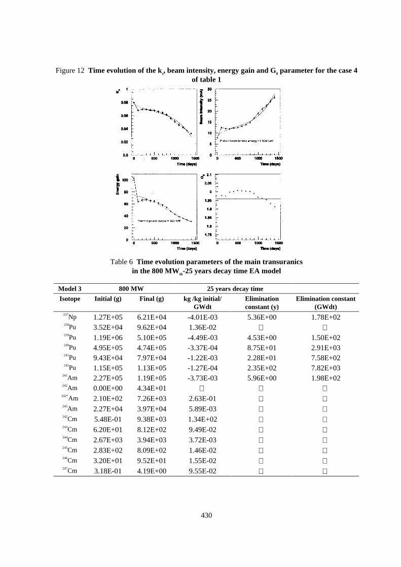
430
Figure 12 Time evolution of the ks, beam intensity, energy gain and G0 parameter for the case 4of table 1
Table 6 Time evolution parameters of the main transuranicsin the 800 MWth-25 years decay time EA model
Model 3 800 MW 25 years decay time
Isotope Initial (g) Final (g) kg /kg initial/GWdt
Eliminationconstant (y)
Elimination constant(GWdt)
237Np 1.27E+05 6.21E+04 -4.01E-03 5.36E+00 1.78E+02238Pu 3.52E+04 9.62E+04 1.36E-02 239Pu 1.19E+06 5.10E+05 -4.49E-03 4.53E+00 1.50E+02240Pu 4.95E+05 4.74E+05 -3.37E-04 8.75E+01 2.91E+03241Pu 9.43E+04 7.97E+04 -1.22E-03 2.28E+01 7.58E+02242Pu 1.15E+05 1.13E+05 -1.27E-04 2.35E+02 7.82E+03
241Am 2.27E+05 1.19E+05 -3.73E-03 5.96E+00 1.98E+02242Am 0.00E+00 4.34E+01
242*Am 2.10E+02 7.26E+03 2.63E-01 243Am 2.27E+04 3.97E+04 5.89E-03 242Cm 5.48E-01 9.38E+03 1.34E+02 243Cm 6.20E+01 8.12E+02 9.49E-02 244Cm 2.67E+03 3.94E+03 3.72E-03 245Cm 2.83E+02 8.09E+02 1.46E-02 246Cm 3.20E+01 9.52E+01 1.55E-02 247Cm 3.18E-01 4.19E+00 9.55E-02

431
Table 6 (cont.) Time evolution parameters of the main transuranics in the 800 MWth-10years decay time EA model
Model 4 800 MW 10 years decay time
Isotope Initial (g) Final (g) kg /kg initial/GWdt
Eliminationconstant (y)
Elimination constant(GWdt)
237Np 1.14E+05 5.46E+04 -4.07E-03 5.22E+00 1.74E+02238Pu 3.66E+04 7.52E+04 8.23E-03 239Pu 1.10E+06 4.64E+05 -4.53E-03 4.43E+00 1.48E+02240Pu 4.57E+05 4.38E+05 -3.25E-04 9.05E+01 3.02E+03241Pu 1.80E+05 9.86E+04 -3.54E-03 6.37E+00 2.12E+02242Pu 1.06E+05 1.08E+05 7.93E-05
241Am 1.21E+05 7.33E+04 -3.09E-03 7.64E+00 2.55E+02242Am 0.00E+00 2.75E+01
242*Am 2.10E+02 4.29E+03 1.52E-01 243Am 2.11E+04 3.73E+04 6.01E-03 242Cm 5.48E-01 5.81E+03 8.29E+01 243Cm 8.21E+01 5.00E+02 3.98E-02 244Cm 4.39E+03 4.68E+03 5.19E-04 245Cm 2.62E+02 1.03E+03 2.30E-02 246Cm 2.97E+01 1.14E+02 2.21E-02 247Cm 2.94E-01 4.77E+00 1.19E-01
A simulation of this strategy applied to the EA model 2 (800 MWth EA) has been performedunder the considered hypothesis for six more burnup cycles. The first cycle was of 1400 days whilethe following six cycles was simulated for a burnup period of 1500 days. The resulting cumulativeTRUs removals as a function of the number of cycle are presented in figure 13. As can be seen, thereis substantial cumulative elimination of 239Pu, 241Am, 240Pu, 237Np and 242Pu which grow almost linearlywith the number of cycles. The 243Am inventory increases from a production of 17.4 kg at the end ofthe first cycle up to 128.7 kg of cumulative production and the end of cycle seven.
Special behaviours come into view for the 238Pu and the 241Pu evolutions: both at the end of cyclenumber three starts to disappear, beginning with two production cycles. The 238Pu is the main productof 237Np conversion by neutron irradiation and the 241Pu is produced by neutron capture in 240Pu. Theseresults indicate that both actinides have reached equilibrium ratios with their parents after the end ofcycle three. In the case of 242Cm and 244Cm there is a linear increase of their cumulative production.Nevertheless, the produced masses are not comparable in scale with the transmutation rates of 239Pu,241Am, 240Pu and 237Np.
The characteristic elimination constants for several TRUs of interest appear in figure 14. As canbe seen, for 237Np, 239Pu and 241Am these constants are nearly cycle independent, with average values of0.19 year-1 for 237Np, 0.21 year-1 for 239Pu and 0.16 year-1 for 241Am. The differences with average valuesare in the three cases less than 5%. Therefore, if the loaded masses at the beginning of every cycle arenear the same, as it is the case, the elimination achieved for the same burnup is the same, and thecumulative elimination is a linear function of the number of cycles, as figure 13 has revealed.
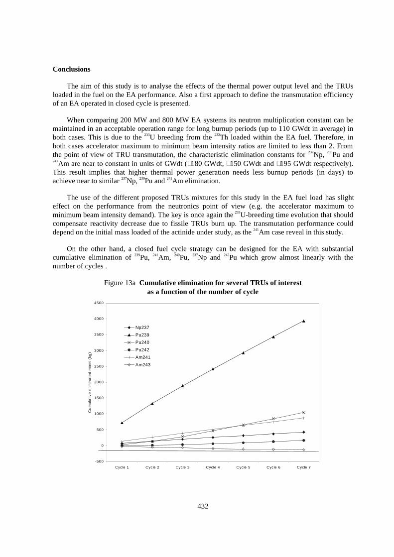
432
Conclusions
The aim of this study is to analyse the effects of the thermal power output level and the TRUsloaded in the fuel on the EA performance. Also a first approach to define the transmutation efficiencyof an EA operated in closed cycle is presented.
When comparing 200 MW and 800 MW EA systems its neutron multiplication constant can bemaintained in an acceptable operation range for long burnup periods (up to 110 GWdt in average) inboth cases. This is due to the 233U breeding from the 232Th loaded within the EA fuel. Therefore, inboth cases accelerator maximum to minimum beam intensity ratios are limited to less than 2. Fromthe point of view of TRU transmutation, the characteristic elimination constants for 237Np, 239Pu and241Am are near to constant in units of GWdt (∼180 GWdt, ∼150 GWdt and ∼195 GWdt respectively).This result implies that higher thermal power generation needs less burnup periods (in days) toachieve near to similar 237Np, 239Pu and 241Am elimination.
The use of the different proposed TRUs mixtures for this study in the EA fuel load has slighteffect on the performance from the neutronics point of view (e.g. the accelerator maximum tominimum beam intensity demand). The key is once again the 233U-breeding time evolution that shouldcompensate reactivity decrease due to fissile TRUs burn up. The transmutation performance coulddepend on the initial mass loaded of the actinide under study, as the 241Am case reveal in this study.
On the other hand, a closed fuel cycle strategy can be designed for the EA with substantialcumulative elimination of 239Pu, 241Am, 240Pu, 237Np and 242Pu which grow almost linearly with thenumber of cycles .
Figure 13a Cumulative elimination for several TRUs of interestas a function of the number of cycle
-500
0
500
1000
1500
2000
2500
3000
3500
4000
4500
Cycle 1 Cycle 2 Cycle 3 Cycle 4 Cycle 5 Cycle 6 Cycle 7
Cu
mu
lativ
e e
limin
ate
d m
ass
(kg
)
Np237
Pu239
Pu240
Pu242
Am241
Am243
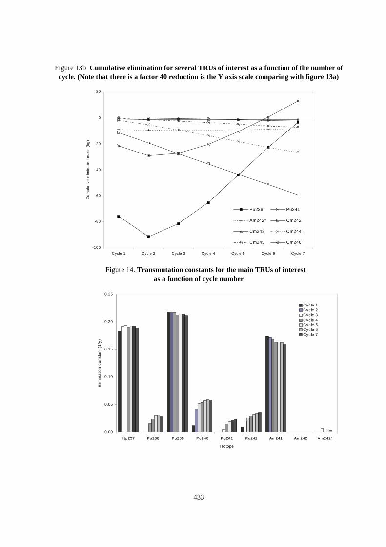
433
Figure 13b Cumulative elimination for several TRUs of interest as a function of the number ofcycle. (Note that there is a factor 40 reduction is the Y axis scale comparing with figure 13a)
-100
-80
-60
-40
-20
0
20
Cycle 1 Cycle 2 Cycle 3 Cycle 4 Cycle 5 Cycle 6 Cycle 7
Cu
mu
lativ
e e
limin
ate
d m
ass
(kg
)
Pu238 Pu241
Am242* Cm242
Cm243 Cm244
Cm245 Cm246
Figure 14. Transmutation constants for the main TRUs of interestas a function of cycle number
0.00
0.05
0.10
0.15
0.20
0.25
Np237 Pu238 Pu239 Pu240 Pu241 Pu242 Am241 Am242 Am242*
Isotope
Elim
ina
tion
co
nst
an
t (1
/y)
Cyc le 1Cycle 2Cycle 3Cycle 4Cycle 5Cycle 6Cycle 7
434
REFERENCES
[1] Accelerator Driven systems: Energy Generation and Transmutation of Nuclear Waste. StatusReport. IAEA-TECDOC-985 1997.
[2] C. Rubbia et al., Conceptual Design of a Fast Neutron Operated High Power Energy Amplifier.CERN/AT/95-44 (ET) 1995.
Rubbia et al., A Realistic Plutonium Elimination Scheme with Fast Energy Amplifiers andThorium-Plutonium Fuel. CERN/AT/95-53 (ET) 1995.
Rubbia et al., Fast Neutron Incineration in the Energy Amplifier As Alternative to GeologicStorage: The Case of Spain. CERN/LHC/97-01 (EET) 1997.
Rubbia,Resonance Enhanced Neutron Captures for Element Activation and WasteTransmutation. CERN/LHC/97-04 (EET) 1997.
[3] M. J. Bell, ORIGEN - The ORNL Isotope Generation and Depletion Code. V ORNL-4628. 1973.
[4] R. Fernández and E. M. González-Romero, Study on the Homogeneous and HeterogeneousGeometry Approaches for a Montecarlo Neutronic Calculation of the Energy Amplifier. InformeTécnico CIEMAT 834 1997.
[5] R. E. MacFarlane and D. W. Muir, The NJOY Nuclear Data Processing System, Version 91,1994.
[6] R. E. Prael and H. Lichtenstein, User Guide to LCS: The LAHET Code System. Group X-6. MS-B226. LANL, 1989.
[7] J. F. Briesmeister, Editor. MCNP - A general Monte Carlo N-particle transport code. Version4B. LA-12625 M., 1997.
435
ACHIEVABLE TRANSMUTATION RATES FOR TRUS AND LLFPS IN MYRRHA
H. Aït Abderrahim, E. Malambu, D. De Maeyer, J.L. Bellefontaine, Ch. De RaedtSCK•CEN
Boeretang 2002400 Mol, Belgium
Abstract
SCK•CEN wants to fulfil a prominent role in the ADS field and is currently establishing a R&Dprogramme to finalise the design of an ADS prototype. Therefore, the ADONIS system, initiallyintended for dedicated radioisotope production, was revisited to give birth to the Myrrha system. Theneed for ADS related R&D as well as the extension of current competencies within SCK•CEN andrelated institutes led to the study of a prototype ADS which would focus primarily on ADS relatedresearch, i.e. on materials and fuel research, on the utilisation of liquid metals and associated aspects,on reactor physics, and subsequently on applications such as transmutation and safety research onsub-critical systems. In this respect, the Myrrha system should become a new major researchinfrastructure for SCK•CEN supporting and enabling the international R&D programmes.
Currently, the study and preliminary conceptual design of the Myrrha system is being finalised andthe basic engineering phase has started. This study will also define the final choice of thecharacteristics of the facility depending on the selected fields of application to be achieved in thismachine. The applications which are considered can be grouped in three blocks; i) continuation, andlater on extension towards ADS, of the ongoing R&D programmes in the field of reactor materials,fuel and reactor physics research; ii) enhancement and triggering of new R&D activities such as wastetransmutation, ADS technology, liquid metal embrittlement; iii) initiation of new competencies suchas medical application (proton therapy, PET production,..), neutron beam applications.
Myrrha will use an accelerator delivering a proton beam of (2 mA, 250 or 350 MeV). The spallationtarget is a liquid Pb-Bi volume circulating in a single closed loop. In its present design the spallationsource is a windowless design. The sub-critical assembly is made of two consecutive zones of fuelrod lattices. Due to the main interest in research on the transmutation of TRUs, the first zone,consisting of MOX-type fuel rods with high Pu contents, forms a fast neutron spectrum region. In thepresent design, the fuel pins are inserted in a lead environment. This lead environment is either a solidblock (cooled with a gas-circuit) or liquid lead, depending on the total power to be removed. The fastneutron zone is surrounded by a thermal neutron zone made of LWR UO2 fuel rods inserted in a watermoderator. This thermal zone will allow to increase the multiplication factor to perform experimentsrelated to LWR fuel research, radioisotope production and transmutation of LLFPs.
In this paper we will report on the performances one can achieve in the present design of Myrrhaconcerning transmutation of TRUs such as Np, Pu, Am, and Cm in the fast neutron zone as well as ofLLFPs such as 129I, 99Tc, 135Cs, and 93Zr in the thermal neutron zone.
436
Introduction
Nuclear energy has to cope with some topics to resolve the economical question of increasingenergy demand and more specially the public acceptability requirements:
− Increasing the absolute safety of the installations.
− Managing more efficiently the nuclear waste.
In that respect, the development of a new type of nuclear installation coping with the aboveconstraints as well as with those of technological, social and economical nature is most important forthe future of sustainable energy provision. Accelerator driven systems are coping with the aboveconstraints and can pave the way to a more environmentally safe and acceptable nuclear energyproduction. Fundamental and applied R&D are crucial in the development of these technologies anddemand the availability of appropriate prototype installations. These prototype installations have toenable and have to deal with these R&D-issues related to accelerator driven system development.
The Myrrha project aims at investigating the design, development and realisation of a versatileneutron source based on an accelerator driven system. It focuses on the realisation of a radiationsource, well-matched to both regional R&D needs and international fundamental researchprogrammes in the field of accelerator driven systems.
The initial project leading to the current Myrrha project focused on the dedicated application ofradioisotope production relying on an accelerator driven system. This project, called ADONIS, hasbeen shifted to the Myrrha project to extend the scope of applications towards :
− material irradiation studies;
− fuel research (transient and high burn-up accumulation);
− radioisotope production;
− waste transmutation studies; and,
− ADS system prototyping from the technological point of view.
These studies lead to refocusing the scale of the system for both the sub-critical assembly and theaccelerator performances to be considered.
Present Design of Myrrha
Accelerator
The accelerator considered up to now is a six sector cyclotron generating a 2 mA current at 250or 350 MeV considered in two stages, the first stage being an injector ranging between 40 and70 MeV. The positive ion (H+) acceleration technology will be used for this machine. IBA isconsidered as the most potential partner for the design of the accelerator. The two stage acceleratoroption is not yet a frozen option: it is kept for potential applications with low energy protons such asradioisotope production using protons or, to a limited extent, proton therapy.
437
Spallation target
The spallation target is made of liquid Pb-Bi circulating in a double concentric cylindrical circuitwith a dump tank at the lower end of the circuit. At the upper part of the target system a free surfaceis in contact with the incoming proton beam. No conventional window is foreseen between the Pb-Bifree surface and the beam in order to keep the energy losses at their minimum. The Pb-Bi iscirculating bottom-top in the outer tube and going down in the central tube leading to the creation of ajet pump effect which will help in trapping the Pb and Po vapours. However, to reduce potentialtransport of volatile substances from the spallation source into the accelerator and related damage, avery thin He-cooled double walled barrier is placed in the beam trajectory at a certain distance fromthe spallation source.
The choice of a windowless design has been influenced by the following considerations :
− With 250 MeV, an incident proton delivers 7 MeV kinetic energy per spallation neutron.Almost 85% of the incident energy is lost as « evaporation » energy of the nuclei in thetarget. The addition of a window would only diminish the fraction of the incident energydelivered to the spallation neutrons.
− A windowless design avoids vulnerable parts in the concept, increasing its reliability.
− The low working temperature in the Pb-Bi eutectic. Indeed, if we consider an inlettemperature of 150°C, we end up with working temperatures of 250°C average temperaturein the central part and 170°C in the outer part, with a circulating speed of 1.8 m/s in bothsections. These low temperatures will result in very low Pb-Po evaporation rates (within therange of 2. 10-8 ~ 10-7 kg/m².s).
The thermo-hydraulics simulation of the windowless design is foreseen in a first stage to becarried out with hot water which is a good equivalent fluid for the Pb-Bi from the comparison of theirdimensionless numbers (Reynolds, Prandtl, Weber)
Sub-critical system
The design of the sub-critical assembly to be set up around the spallation source is application-dependent. Indeed, one should meet the neutronic performances as well as the volumes needed by theconsidered applications. The present design of the Myrrha sub-critical system is shown in Figure 1below.
In that respect, to meet our goals of material studies, fuel behaviour studies, radioisotopesproduction, transmutation of MAs and LLFPs studies, we came to the conclusion that the sub-criticalsystem of Myrrha should have two spectral zones ; a fast neutron spectrum zone and a thermalspectrum one. We should have irradiation channels having sufficiently large volumes for housingirradiation rigs such as the ones used in MTRs. Therefore, we should have a spallation source withaxial distribution leading to a reasonable axial active length. This resulted in choosing a higherincident proton energy: 350 MeV instead of 250 MeV leading to a spallation-source axial distributionof 15 cm instead of 10 cm.
Besides these considerations, our objectives during this pre-design were to avoid the use ofrevolutionary technologies from the point of view of the components to be used. The targeted Ksource
value is 0.9: this value could be increased after having performed the necessary safety studies. The
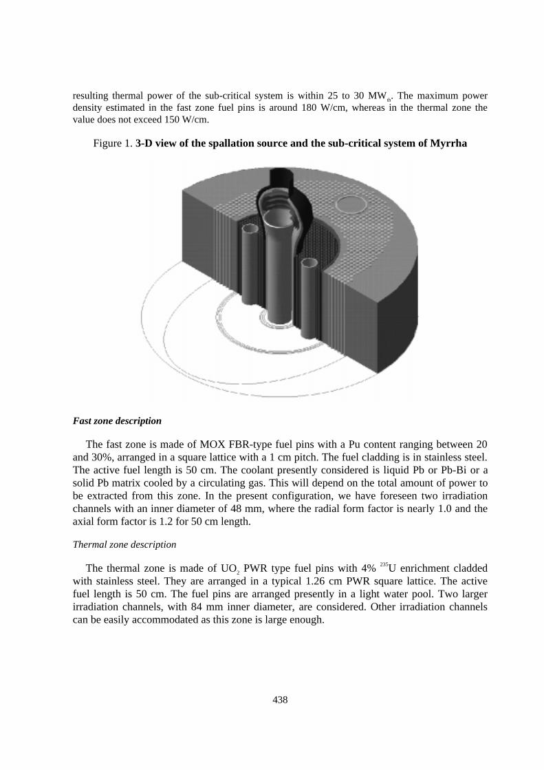
438
resulting thermal power of the sub-critical system is within 25 to 30 MWth. The maximum powerdensity estimated in the fast zone fuel pins is around 180 W/cm, whereas in the thermal zone thevalue does not exceed 150 W/cm.
Figure 1. 3-D view of the spallation source and the sub-critical system of Myrrha
Fast zone description
The fast zone is made of MOX FBR-type fuel pins with a Pu content ranging between 20and 30%, arranged in a square lattice with a 1 cm pitch. The fuel cladding is in stainless steel.The active fuel length is 50 cm. The coolant presently considered is liquid Pb or Pb-Bi or asolid Pb matrix cooled by a circulating gas. This will depend on the total amount of power tobe extracted from this zone. In the present configuration, we have foreseen two irradiationchannels with an inner diameter of 48 mm, where the radial form factor is nearly 1.0 and theaxial form factor is 1.2 for 50 cm length.
Thermal zone description
The thermal zone is made of UO2 PWR type fuel pins with 4% 235U enrichment claddedwith stainless steel. They are arranged in a typical 1.26 cm PWR square lattice. The activefuel length is 50 cm. The fuel pins are arranged presently in a light water pool. Two largerirradiation channels, with 84 mm inner diameter, are considered. Other irradiation channelscan be easily accommodated as this zone is large enough.
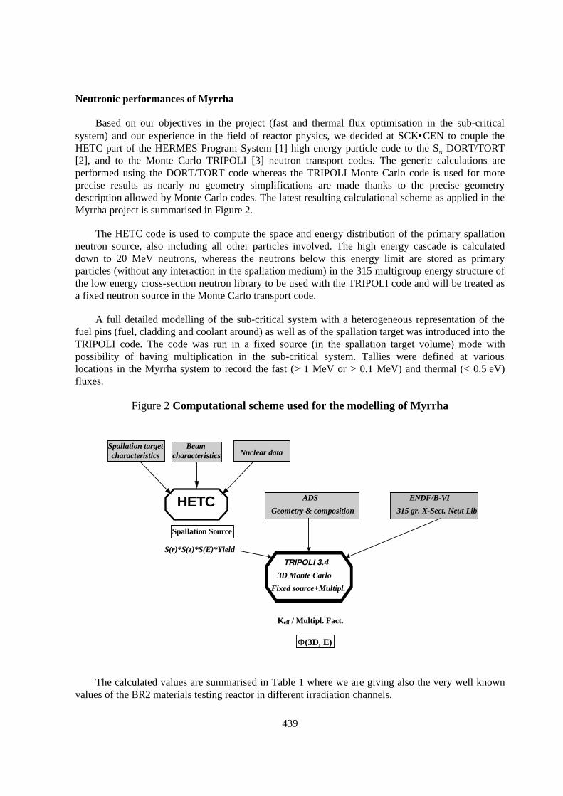
439
Neutronic performances of Myrrha
Based on our objectives in the project (fast and thermal flux optimisation in the sub-criticalsystem) and our experience in the field of reactor physics, we decided at SCK•CEN to couple theHETC part of the HERMES Program System [1] high energy particle code to the SN DORT/TORT[2], and to the Monte Carlo TRIPOLI [3] neutron transport codes. The generic calculations areperformed using the DORT/TORT code whereas the TRIPOLI Monte Carlo code is used for moreprecise results as nearly no geometry simplifications are made thanks to the precise geometrydescription allowed by Monte Carlo codes. The latest resulting calculational scheme as applied in theMyrrha project is summarised in Figure 2.
The HETC code is used to compute the space and energy distribution of the primary spallationneutron source, also including all other particles involved. The high energy cascade is calculateddown to 20 MeV neutrons, whereas the neutrons below this energy limit are stored as primaryparticles (without any interaction in the spallation medium) in the 315 multigroup energy structure ofthe low energy cross-section neutron library to be used with the TRIPOLI code and will be treated asa fixed neutron source in the Monte Carlo transport code.
A full detailed modelling of the sub-critical system with a heterogeneous representation of thefuel pins (fuel, cladding and coolant around) as well as of the spallation target was introduced into theTRIPOLI code. The code was run in a fixed source (in the spallation target volume) mode withpossibility of having multiplication in the sub-critical system. Tallies were defined at variouslocations in the Myrrha system to record the fast (> 1 MeV or > 0.1 MeV) and thermal (< 0.5 eV)fluxes.
Figure 2 Computational scheme used for the modelling of Myrrha
HETC ADS
Geometry & composition
ENDF/B-VI
315 gr. X-Sect. Neut Lib
S(r)*S(z)*S(E)*Yield
TRIPOLI 3.4
3D Monte Carlo
Fixed source+Multipl.
Keff / Multipl. Fact.
Beamcharacteristics Nuclear data
Spallation targetcharacteristics
Spallation Source
Φ(3D, E)
The calculated values are summarised in Table 1 where we are giving also the very well knownvalues of the BR2 materials testing reactor in different irradiation channels.
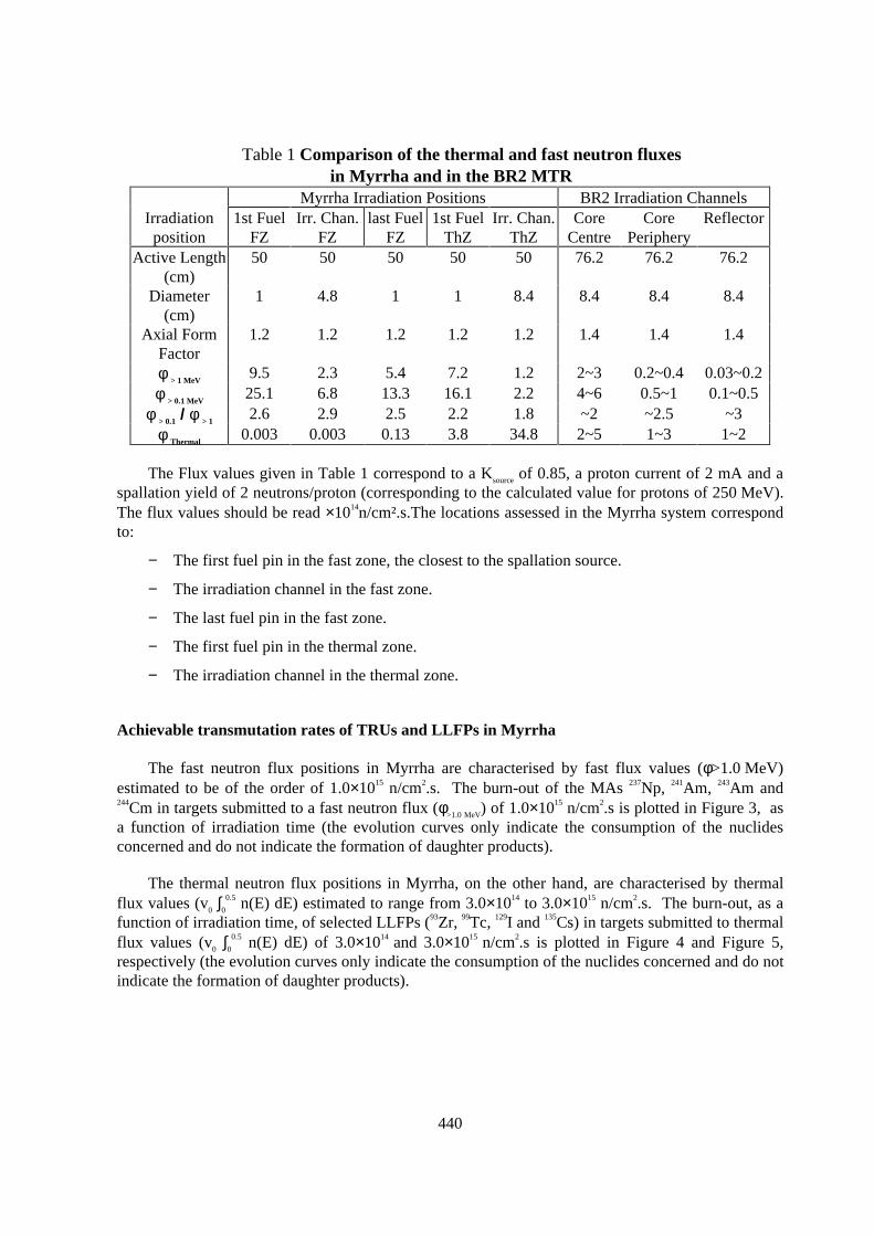
440
Table 1 Comparison of the thermal and fast neutron fluxesin Myrrha and in the BR2 MTR
Myrrha Irradiation Positions BR2 Irradiation ChannelsIrradiationposition
1st FuelFZ
Irr. Chan.FZ
last FuelFZ
1st FuelThZ
Irr. Chan.ThZ
CoreCentre
CorePeriphery
Reflector
Active Length(cm)
50 50 50 50 50 76.2 76.2 76.2
Diameter(cm)
1 4.8 1 1 8.4 8.4 8.4 8.4
Axial FormFactor
1.2 1.2 1.2 1.2 1.2 1.4 1.4 1.4
φ > 1 MeV9.5 2.3 5.4 7.2 1.2 2~3 0.2~0.4 0.03~0.2
φ > 0.1 MeV25.1 6.8 13.3 16.1 2.2 4~6 0.5~1 0.1~0.5
φ > 0.1 / φ > 12.6 2.9 2.5 2.2 1.8 ~2 ~2.5 ~3
φ Thermal0.003 0.003 0.13 3.8 34.8 2~5 1~3 1~2
The Flux values given in Table 1 correspond to a Ksource of 0.85, a proton current of 2 mA and aspallation yield of 2 neutrons/proton (corresponding to the calculated value for protons of 250 MeV).The flux values should be read ×1014n/cm².s.The locations assessed in the Myrrha system correspondto:
− The first fuel pin in the fast zone, the closest to the spallation source.
− The irradiation channel in the fast zone.
− The last fuel pin in the fast zone.
− The first fuel pin in the thermal zone.
− The irradiation channel in the thermal zone.
Achievable transmutation rates of TRUs and LLFPs in Myrrha
The fast neutron flux positions in Myrrha are characterised by fast flux values (φ>1.0 MeV)estimated to be of the order of 1.0×10¹⁵ n/cm2.s. The burn-out of the MAs 237Np, 241Am, 243Am and244Cm in targets submitted to a fast neutron flux (φ>1.0 MeV) of 1.0×10¹⁵ n/cm2.s is plotted in Figure 3, asa function of irradiation time (the evolution curves only indicate the consumption of the nuclidesconcerned and do not indicate the formation of daughter products).
The thermal neutron flux positions in Myrrha, on the other hand, are characterised by thermalflux values (v0 ∫0
0.5 n(E) dE) estimated to range from 3.0×10¹⁴ to 3.0×10¹⁵ n/cm2.s. The burn-out, as afunction of irradiation time, of selected LLFPs (93Zr, 99Tc, 129I and 135Cs) in targets submitted to thermalflux values (v0 ∫0
0.5 n(E) dE) of 3.0×10¹⁴ and 3.0×10¹⁵ n/cm2.s is plotted in Figure 4 and Figure 5,respectively (the evolution curves only indicate the consumption of the nuclides concerned and do notindicate the formation of daughter products).
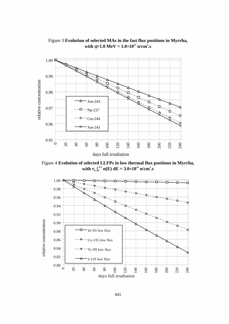
441
Figure 3 Evolution of selected MAs in the fast flux positions in Myrrha,with φ>1.0 MeV = 1.0×10¹⁵ n/cm2.s
0.95
0.96
0.97
0.98
0.99
1.000 20 40 60 80 100
120
140
160
180
200
220
240
days full irradiation
rela
tive
conc
entr
atio
n
Am-243
Np-237
Cm-244
Am-241
Figure 4 Evolution of selected LLFPs in low thermal flux positions in Myrrha,with v0 ∫0
0.5 n(E) dE = 3.0×10¹⁴ n/cm2.s
0.80
0.82
0.84
0.86
0.88
0.90
0.92
0.94
0.96
0.98
1.00
0 20 40 60 80 100
120
140
160
180
200
220
240
days full irradiation
rela
tive
conc
entr
atio
n
Zr-93 low flux
Cs-135 low flux
Tc-99 low flux
I-129 low flux
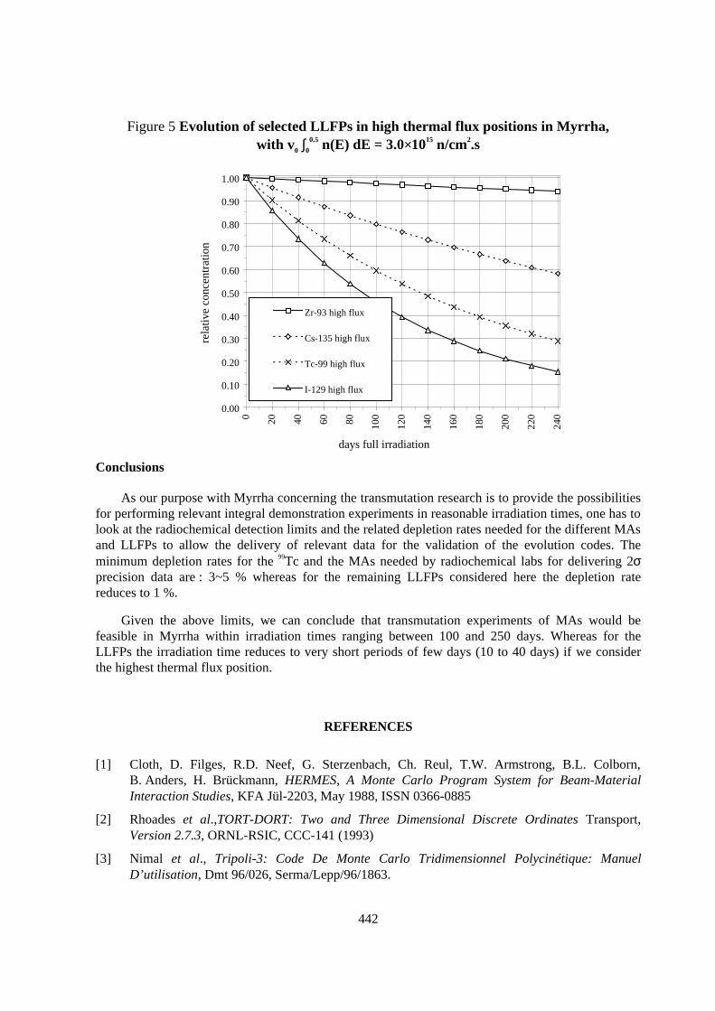
442
Figure 5 Evolution of selected LLFPs in high thermal flux positions in Myrrha,with v0 ∫0
0.5 n(E) dE = 3.0×10¹⁵ n/cm2.s
0.00
0.10
0.20
0.30
0.40
0.50
0.60
0.70
0.80
0.90
1.00
0 20 40 60 80 100
120
140
160
180
200
220
240
days full irradiation
rela
tive
conc
entr
atio
n
Zr-93 high flux
Cs-135 high flux
Tc-99 high flux
I-129 high flux
Conclusions
As our purpose with Myrrha concerning the transmutation research is to provide the possibilitiesfor performing relevant integral demonstration experiments in reasonable irradiation times, one has tolook at the radiochemical detection limits and the related depletion rates needed for the different MAsand LLFPs to allow the delivery of relevant data for the validation of the evolution codes. Theminimum depletion rates for the 99Tc and the MAs needed by radiochemical labs for delivering 2σprecision data are : 3~5 % whereas for the remaining LLFPs considered here the depletion ratereduces to 1 %.
Given the above limits, we can conclude that transmutation experiments of MAs would befeasible in Myrrha within irradiation times ranging between 100 and 250 days. Whereas for theLLFPs the irradiation time reduces to very short periods of few days (10 to 40 days) if we considerthe highest thermal flux position.
REFERENCES
[1] Cloth, D. Filges, R.D. Neef, G. Sterzenbach, Ch. Reul, T.W. Armstrong, B.L. Colborn,B. Anders, H. Brückmann, HERMES, A Monte Carlo Program System for Beam-MaterialInteraction Studies, KFA Jül-2203, May 1988, ISSN 0366-0885
[2] Rhoades et al.,TORT-DORT: Two and Three Dimensional Discrete Ordinates Transport,Version 2.7.3, ORNL-RSIC, CCC-141 (1993)
[3] Nimal et al., Tripoli-3: Code De Monte Carlo Tridimensionnel Polycinétique: ManuelD’utilisation, Dmt 96/026, Serma/Lepp/96/1863.
443
THE CZECH NATIONAL R&D PROGRAM OF NUCLEAR INCINERATION OF PWRSPENT FUEL IN A TRANSMUTER WITH LIQUID FUEL
M. HronNuclear Research Institute Rez plc, CZ-250 68 Re,
Czech Republic
Abstract
The principle drawbacks of any kind of solid nuclear fuel are listed and briefly analysed in the firstpart of the paper. On the basis of this analysis, the liquid fuel concept and its benefits are introducedand briefly described in the following parts of the paper allowing to develop new reactor systems fornuclear incineration of spent fuel from conventional reactors and a new clean source of energy. Asone of the first realistic attempts to utilise the advantages of liquid fuel, the reactor/blanket systemwith molten fluoride salts in the role of fuel and coolant simultaneously, as incorporated in theaccelerator-driven transmutation technology (ADTT) being proposed in [1], has been proposed for adeeper, both theoretical and experimental studies in [2]. There will be a preliminary design concept ofan experimental assembly LA-0 briefly introduced in the paper which is under preparation in theCzech Republic for such a project [3].
444
Introduction
There are principle drawbacks of any kind of solid nuclear fuel listed and analysed in the firstpart of this paper. One of the primary results of the analyses performed shows that the solid fuelconcept, which was to certain degree advantageous in the first periods of a nuclear reactordevelopment and operation, has guided this branch of a utilisation of atomic nucleus energy to a deathend (not having been able to solve principle problems of the corresponding fuel cycle in an acceptableway). On the basis of this, the liquid fuel concept and its benefits are introduced and briefly describedin the following part of the paper.
As one of the first realistic attempts to utilise the advantages of liquid fuel, the reactor/blanketsystem with molten fluoride salts in the role of fuel and coolant simultaneously, as incorporated in theaccelerator-driven transmutation technology (ADTT) being proposed in [1], has been studied boththeoretically and experimentally. There is a preliminary design concept of an experimental assemblyLA-0 briefly introduced in the following para which is under preparation in the Czech Republic forsuch a project.
Finally, there will be another very promising concept [4,5] of a small low power ADTT systemintroduced which is characterised by a high level of safety and economical efficiency. This subcriticalsystem with liquid fuel driven by a linear electron accelerator represents an additional element- nuclear incinerator - to the nuclear power complex (based upon thermal and partly even fast criticalpower reactors) making the whole complex acceptable and simultaneously giving an alternative alsovery highly acceptable nuclear source of energy and even other products (e.g. radionuclides, etc.). Inthe conclusion, the overall survey of principal benefits which may be expected by introducing liquidnuclear fuel in nuclear power and research reactor systems is given and critically analysed. The othercomparably important principles (e.g. the general subcriticality of reactor systems principle) arementioned which being applied in the nearest future may form a basis for an absolutely new nuclearreactor concept and a new nuclear power era at all.
Solid nuclear fuel concept drawbacks
In spite of the fact that all what is following is well known it seems to be worth to remind it inthe new circumstances of nuclear power at the end of the 20th century while starting to search newnuclear energy systems and fuel cycle options for the 21st century. Since the discovery of the reactionof atomic nucleus fission, the main goal of all efforts was to utilise it for an energy generation. As oneof the most important conditions for an efficient achievement of this goal self-sustaining of fissionchain reaction was demanded in an assembly containing fissionable nuclei of nuclear fuel without anexternal source of neutrons. If this was reached, the assembly was defined as being critical. Let usnote that it was by definition (theoretically) critical on prompt neutrons released, immediately, fromfission reactions only. Very early, it was observed experimentally that the assembly reachingcriticality is in fact very slightly subcritical on prompt neutrons and that there is a not very strongnatural source of delayed neutrons originated from radioactive decay of some of the fission productsalways added (which, fortunately, allowed easier control of the system).
At the early stages, the reaching of criticality was one of the most difficult tasks and all the effortand ideas had been devoted to this aim. The reason was that there were only small amounts offissionable materials available in those times in the form of the low (0.7%) content of U235 in naturaluranium. Therefore, solid phase metallic uranium with highest as possible density was used and in the
445
form of blocks with a specifically defined size arranged in a heterogeneous lattice filled in by a solid(graphite) or liquid (heavy water) moderator with a certain pitch determined by optimal neutronicconditions. This arrangement has remained nearly exclusive one being used even in latter systemswith fuels enriched by U235 content up to much higher levels than the content of natural compositionof uranium. The reasons were of different nature, however, the designs have mostly started from whatbecame already an approved conventional principle - solid fuel blocks in a heterogeneous lattice -which has been kept even in the case of pure or high enriched fuel in a fast neutron system withoutmoderator.
One of the next consequences of the adoption of the solid fuel concept has been a type of controlsystem which has been mostly applied for a short term control of nuclear reactors - the concept ofsolid absorbers - and what is more, the concept of a negative neutron source (neutron poison) at all.This, and a number of other consequences, can be traced to start all from the initial tension in neutroneconomy when the principle of a self-sustaining fission chain reaction and consequently the conceptof a critical reactor have been adopted in nuclear reactor technology . They all begin to form a magiccircle of convention in which the short term and finally even long term operational behaviour ofnuclear, namely power, reactors is being imprisoned and limited in its ability to give a positive andbroadly acceptable development. Let us explain this thesis in some following more see-throughexamples.
The adoption of the solid fuel concept leads to the principal necessity to keep the fuel blocks at acertain position in the reactor core for a shorter or longer period of time. This in-core residential timeis especially long in power systems where at least a quasi-continuous exchange of fuel would be verycomplicated and expensive. Therefore, the following very inconvenient consequence arises: the wholetime, the block of solid fuel remains at a certain position in the reactor core, there are fissionfragments and by neutron capture induced radionuclides (let us call them altogether products) beingaccumulated in the volume of the fuel block. There are several secondary consequences caused bythis fact which contribute to the above mentioned magic circle forming:
1. Reactivity margin for a short term as well as long term negative influence of the increasinglyaccumulated products has to be applied which has to be compensated by another artificialnegative source of neutrons. It has, in principle, another consequence in the greater amountof fuel being present in the core than really necessary for the demanded power and then themore products including actinides is generated in the system.
2. The original fuel is finally so heavily poisoned by the products that it cannot keep theself-sustained fission chain reaction any more and a further operation of the reactorunder original conditions is impossible. A principle change in the operation andstructure of the reactor becomes to be unavoidable what means an outage and exchangeof at least a part of the original fuel charge.
3. The most controversial problem what to do with spent solid fuel arises and a viciouscircle has been closed or a solid fuel concept “trap” snapped.
The above briefly described solid fuel concept shows its most important and sensitivedrawbacks: 1) continuous accumulation of products during the whole residential time of fuel blocksin the core, 2) following necessity to stop the operation, discharge spent fuel and store it for anecessary period of time (in order of magnitude of years until it reaches a desirably low level ofradioactivity) in a specific storage, 3) the last and the most difficult drawback is the need of anoptimal decision of the following destiny of spent fuel.
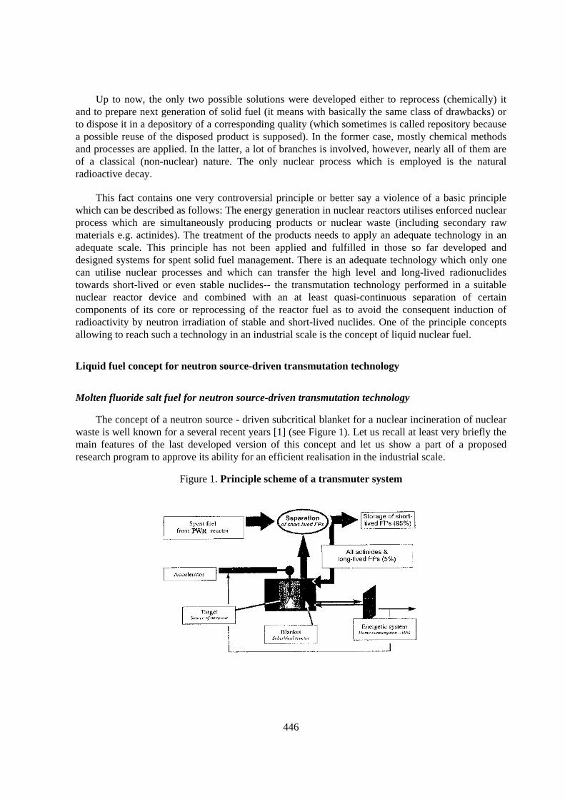
446
Up to now, the only two possible solutions were developed either to reprocess (chemically) itand to prepare next generation of solid fuel (it means with basically the same class of drawbacks) orto dispose it in a depository of a corresponding quality (which sometimes is called repository becausea possible reuse of the disposed product is supposed). In the former case, mostly chemical methodsand processes are applied. In the latter, a lot of branches is involved, however, nearly all of them areof a classical (non-nuclear) nature. The only nuclear process which is employed is the naturalradioactive decay.
This fact contains one very controversial principle or better say a violence of a basic principlewhich can be described as follows: The energy generation in nuclear reactors utilises enforced nuclearprocess which are simultaneously producing products or nuclear waste (including secondary rawmaterials e.g. actinides). The treatment of the products needs to apply an adequate technology in anadequate scale. This principle has not been applied and fulfilled in those so far developed anddesigned systems for spent solid fuel management. There is an adequate technology which only onecan utilise nuclear processes and which can transfer the high level and long-lived radionuclidestowards short-lived or even stable nuclides-- the transmutation technology performed in a suitablenuclear reactor device and combined with an at least quasi-continuous separation of certaincomponents of its core or reprocessing of the reactor fuel as to avoid the consequent induction ofradioactivity by neutron irradiation of stable and short-lived nuclides. One of the principle conceptsallowing to reach such a technology in an industrial scale is the concept of liquid nuclear fuel.
Liquid fuel concept for neutron source-driven transmutation technology
Molten fluoride salt fuel for neutron source-driven transmutation technology
The concept of a neutron source - driven subcritical blanket for a nuclear incineration of nuclearwaste is well known for a several recent years [1] (see Figure 1). Let us recall at least very briefly themain features of the last developed version of this concept and let us show a part of a proposedresearch program to approve its ability for an efficient realisation in the industrial scale.
Figure 1. Principle scheme of a transmuter system
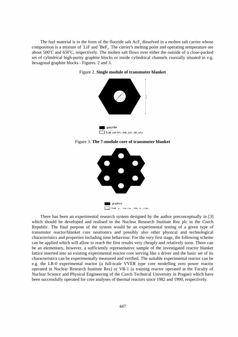
447
The fuel material is in the form of the fluoride salt AcF4 dissolved in a molten salt carrier whosecomposition is a mixture of 7LiF and 9BeF2. The carrier’s melting point and operating temperature areabout 500oC and 650oC, respectively. The molten salt flows over either the outside of a close-packedset of cylindrical high-purity graphite blocks or inside cylindrical channels coaxially situated in e.g.hexagonal graphite blocks - Figures. 2 and 3.
Figure 2. Single module of transmuter blanket
Figure 3. The 7-module core of transmuter blanket
There has been an experimental research system designed by the author preconceptually in [3]which should be developed and realised in the Nuclear Research Institute Rez plc in the CzechRepublic. The final purpose of the system would be an experimental testing of a given type oftransmuter reactor/blanket core neutronics and possibly also other physical and technologicalcharacteristics and properties including time behaviour. For the very first stage, the following schemecan be applied which will allow to reach the first results very cheaply and relatively soon. There canbe an elementary, however, a sufficiently representative sample of the investigated reactor blanketlattice inserted into an existing experimental reactor core serving like a driver and the basic set of itscharacteristics can be experimentally measured and verified. The suitable experimental reactor can bee.g. the LR-0 experimental reactor (a full-scale VVER type core modelling zero power reactoroperated in Nuclear Research Institute Rez) or VR-1 (a training reactor operated at the Faculty ofNuclear Science and Physical Engineering of the Czech Technical University in Prague) which havebeen successfully operated for core analyses of thermal reactors since 1982 and 1990, respectively.
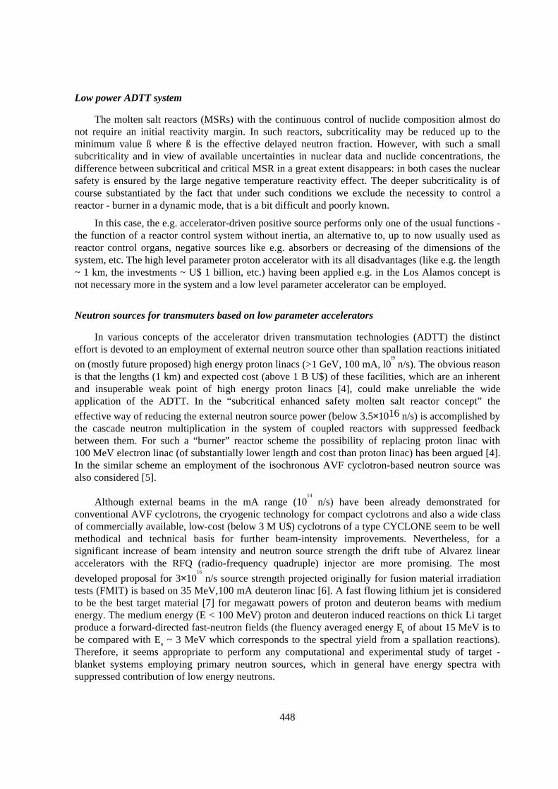
448
Low power ADTT system
The molten salt reactors (MSRs) with the continuous control of nuclide composition almost donot require an initial reactivity margin. In such reactors, subcriticality may be reduced up to theminimum value ß where ß is the effective delayed neutron fraction. However, with such a smallsubcriticality and in view of available uncertainties in nuclear data and nuclide concentrations, thedifference between subcritical and critical MSR in a great extent disappears: in both cases the nuclearsafety is ensured by the large negative temperature reactivity effect. The deeper subcriticality is ofcourse substantiated by the fact that under such conditions we exclude the necessity to control areactor - burner in a dynamic mode, that is a bit difficult and poorly known.
In this case, the e.g. accelerator-driven positive source performs only one of the usual functions -the function of a reactor control system without inertia, an alternative to, up to now usually used asreactor control organs, negative sources like e.g. absorbers or decreasing of the dimensions of thesystem, etc. The high level parameter proton accelerator with its all disadvantages (like e.g. the length~ 1 km, the investments ~ U$ 1 billion, etc.) having been applied e.g. in the Los Alamos concept isnot necessary more in the system and a low level parameter accelerator can be employed.
Neutron sources for transmuters based on low parameter accelerators
In various concepts of the accelerator driven transmutation technologies (ADTT) the distincteffort is devoted to an employment of external neutron source other than spallation reactions initiated
on (mostly future proposed) high energy proton linacs (>1 GeV, 100 mA, l0l9
n/s). The obvious reasonis that the lengths (1 km) and expected cost (above 1 B U$) of these facilities, which are an inherentand insuperable weak point of high energy proton linacs [4], could make unreliable the wideapplication of the ADTT. In the “subcritical enhanced safety molten salt reactor concept” the
effective way of reducing the external neutron source power (below 3.5×10¹⁶ n/s) is accomplished bythe cascade neutron multiplication in the system of coupled reactors with suppressed feedbackbetween them. For such a “burner” reactor scheme the possibility of replacing proton linac with100 MeV electron linac (of substantially lower length and cost than proton linac) has been argued [4].In the similar scheme an employment of the isochronous AVF cyclotron-based neutron source wasalso considered [5].
Although external beams in the mA range (1014
n/s) have been already demonstrated forconventional AVF cyclotrons, the cryogenic technology for compact cyclotrons and also a wide classof commercially available, low-cost (below 3 M U$) cyclotrons of a type CYCLONE seem to be wellmethodical and technical basis for further beam-intensity improvements. Nevertheless, for asignificant increase of beam intensity and neutron source strength the drift tube of Alvarez linearaccelerators with the RFQ (radio-frequency quadruple) injector are more promising. The most
developed proposal for 3×10¹⁶
n/s source strength projected originally for fusion material irradiationtests (FMIT) is based on 35 MeV,100 mA deuteron linac [6]. A fast flowing lithium jet is consideredto be the best target material [7] for megawatt powers of proton and deuteron beams with mediumenergy. The medium energy (E < 100 MeV) proton and deuteron induced reactions on thick Li targetproduce a forward-directed fast-neutron fields (the fluency averaged energy En of about 15 MeV is tobe compared with En ~ 3 MeV which corresponds to the spectral yield from a spallation reactions).Therefore, it seems appropriate to perform any computational and experimental study of target -blanket systems employing primary neutron sources, which in general have energy spectra withsuppressed contribution of low energy neutrons.
449
In the NPI Rez, the d(18 MeV)+Be neutron generator, originally developed for the militarydirected research is now being upgraded with the main task to take advantage of H- and D- negativeions recently implemented on the NPI isochronous cyclotron U-120M. Conversion of the cyclotroninto H-, D- machine enabled to utilise a high efficient extraction by means of the stripping, whichresulted in substantially increased extracted beam currents of positive p+ and d+ ions. Nowadays, up to20 µA currents of the 15 - 30 MeV protons are routinely extracted to various types of targets forradionuclides production. The purpose of employing this beams for fast neutron production is toperform a broad range of experiments closely related to the activation analysis and ADTT program aswell.
For ADTT empirical research in NPI, an experimental study of the spectral and yieldcharacteristics of various neutron produced reactions between light nuclei is now under way, the maintasks of which are as follows: a) to verify yield calculations from cross-section data, b) to determinean empirical shape of spectral yield of neutrons from deuteron break-up processes so as it can not bepredicted reliably from simple phase-space calculations, and c) to determine the contribution of thetarget- v station arrangement to the background part of produced neutron fields. Knowledge of thesecharacteristics is needed to evaluate the target and beam options for the best simulation of ADTTexternal neutron source mentioned above. The results of first experiments were found to be in a goodagreement with calculations based on updated cross-section database (EXFOR). The preliminary
calculations show that for the present neutron facility the neutron source strength up to 6×10¹²
n/s.srand fluency averaged neutron energy En =15 MeV could be achieved from thick deuterium targetirradiated by 30 MeV protons.
Blanket concept of at Transmuter for PWR spent fuel incineration
There has been a convenient blanket concept for an efficient nuclear incineration of PWR spentfuel developed as a combination of those two ideas described in two paragraphs above. The concept isillustrated by the Figure 4, where two zones are indicated, one under-moderated and thus betterequipped for actinides burning and the second well-moderated (fuel channel in a graphite block) andthus more convenient for fission products incineration.
Experience in fluorine technology and application of fluoride liquid fuel in ADTT
There has been a technological process worked-out for the separation of uranium and plutoniumfrom the spent fuel by a dry (fluorine) method in the NRI, Rez, in a close collaboration with theKurchatov Institute, Moscow, during the 80s. The whole process was upgraded to a pilot plant scalewith a capacity of 1-3kg of processed fuel/hour. There was a part of the technological equipment builtand verified at an inactive scale at the NRI Rez. The whole technological line called Fregat (Figure 5)was then realised in the Institute of Atomic Reactors at Dimitrovgrad, Russia, and all processesproved by reprocessing of spent fuel from the fast reactor BOR 60. All equipment including fittings,measuring instruments and accessories have been built in the former Czechoslovakia, the plutoniumpart of the pilot plant has been built in the former USSR. A certain experience has also been obtainedon the uranium isotopes separation by ultra-centrifugation and electrochemical processes.
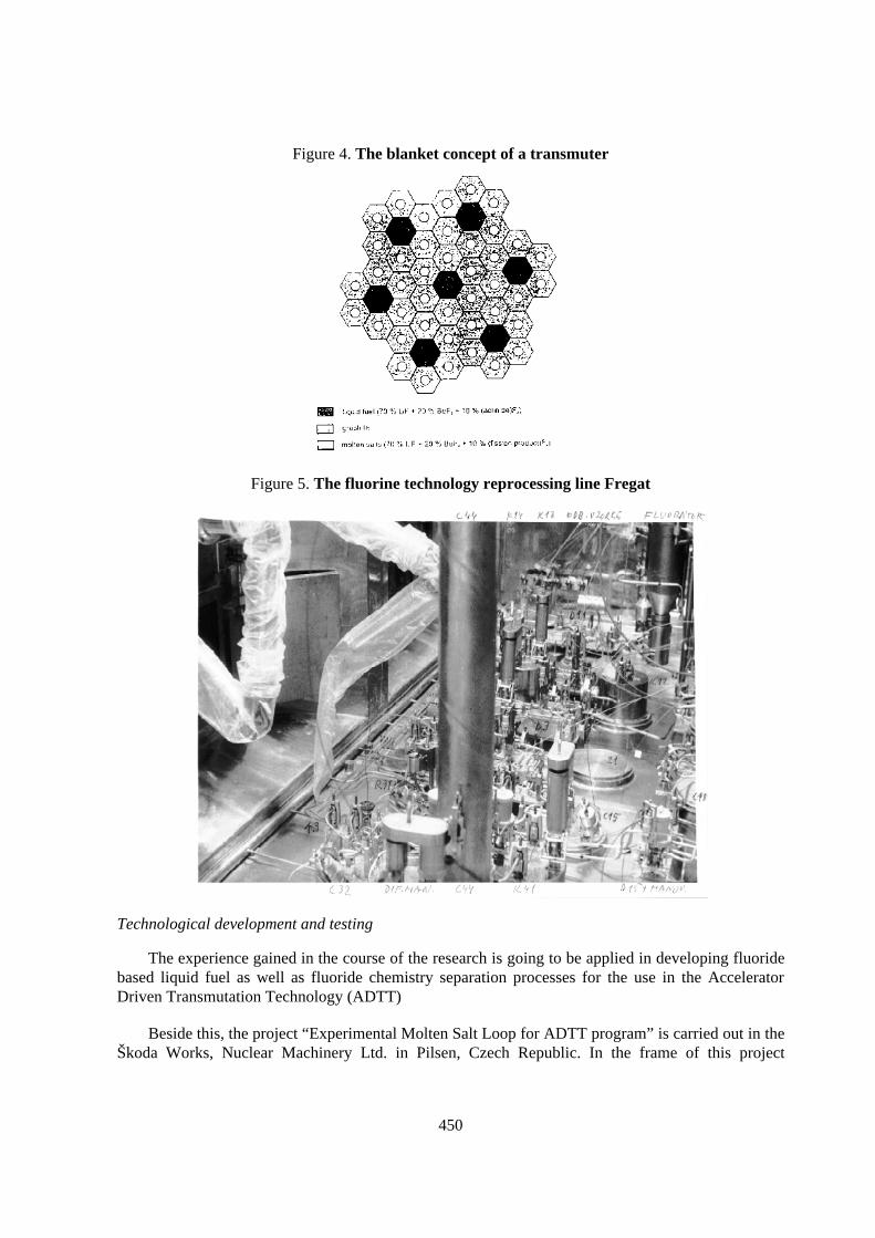
450
Figure 4. The blanket concept of a transmuter
Figure 5. The fluorine technology reprocessing line Fregat
Technological development and testing
The experience gained in the course of the research is going to be applied in developing fluoridebased liquid fuel as well as fluoride chemistry separation processes for the use in the AcceleratorDriven Transmutation Technology (ADTT)
Beside this, the project “Experimental Molten Salt Loop for ADTT program” is carried out in theŠkoda Works, Nuclear Machinery Ltd. in Pilsen, Czech Republic. In the frame of this project
451
technological loop for studying of molten fluoride salts characteristics was designed and fabricatedand then installed in the NRI Rez which will start up an experimental program till the end of 1998.
Conclusions
The analyses of spent fuel management from PWRs as well as all other nuclear reactorsemploying solid fuel concept have showed the principal drawbacks of that concept causing a series ofconsequences leading to a crucial issue of a nowadays nuclear power – spent solid fuel withaccumulated actinides and long-lived fission products (without regard whether the open nuclear fuelcycle or a multiple reprocessing is applied). The necessity of an employment of nuclear processes andan adequate nuclear technology (nuclear incineration) in an efficient solution of that problem isdefinitely evident. The national R&D programme which was very briefly introduced in this paper isclosely connected with the world - wide effort of research teams in leading countries of nuclear powerlike e.g. France, USA, Russia and Japan and forms a contribution to the common effort in the solutionof that global issue. The overall co-operation in this field gives a real chance to make nuclear poweracceptable as a clean source of energy for the 21st century.
REFERENCES
[1] Bowman C.D. et al., Nuclear Energy Generation and Waste Transmutation Using anAccelerator - Driven Intense Neutron Source. Nucl.Instr. and Meth. in Phys. Res. A 320 (1992)336.
[2] Hron M., A Preliminary Design Concept of the Experimental Assembly LA-0 for Accelerator-Driven Transmuter Reactor/Blanket Core Neutronics and Connected Technology Testing, LA-UR 95-376. Los Alamos National Laboratory, 1995.
[3] Hron M. et al., The LA-0 Transmuter : Development of New Technologies of NuclearIncineration of VVER Spent Fuel and Operational RAD Waste. NRI Øe R&D Project 1998.
[4] Alekseyev P.N. et al., Subcritical Enhanced Molten - Salt Reactor Concept. GLOBAL'95,Versailles, September 11 - 14, 1995.
[5] Alekseyev P.N. et al., Molten Salt Reactor Concept with a Higher Safety, Report of the RussianScientific Center Kurchatov Institute, IAE - 5857/2, 1995.
[6] T. E. Shannon et al., Conceptual Design of IFMF, l6th Internat. Conf. on Plasma Physics andControlled Nuclear Fusion Res., Montreal, Oct. 7.-1 I , 1996.
[7] IFMIF/CDA, Interim Report ORNl,/M-4908, compiled by M. J. Rennich, Oak Ridge. USA,Dec.1995.
[8] Avery R., Theory of coupled reactors, Proceedings of the Second United Nations InternationalConference, Geneva, pp.182-191, 1958.
[9] Hummel L. et al., Experimental and Theoretical Research of Fast-Thermal Coupled ReactorSystem, ibid, pp. 201-230.

453
THE EFFECTIVENESS OF FAST AND THERMAL SPECTRUM FOR TRUINCINERATION IN SUBCRITICAL SYSTEM
Won S. Park, Hyung Jin SimKorea Atomic Energy Research Institute
P.O.Box 105, Yusong, TaejeonRepublic of Korea
Abstract
An investigation to compare the relative effectiveness of fast neutron with thermal neutron in asubcritical system has been performed. Accelerator driven thermal and fast neutron systems aremodelled on a CANDU reactor and a typical LMR with Pb-Bi coolant, respectively. TRU mixed withThorium was selected as a fuel in both systems. The ratio of TRU to Thorium is adjusted to make thesystem subcriticality about 0.97 and the system output power is set to be 1000 MWth. The thermalsystem was found to have unacceptable beam fluctuation and power peaking variations. Thecharacteristics of thermal neutron are believed not to allow the employment of solid fuel concept in athermal neutron subcritical system. In addition, the sensitiveness of thermal neutron to theconcentration of TRU and fission products is believed to inevitably require on-line refuelling forreducing the beam power fluctuation. From the overall comparison, a fast neutron is concluded to bemuch better for the operation of the subcritical system.
454
Introduction
Korea Atomic Energy Research Institute (KAERI) is performing the project to develop anaccelerator driven transmutation system, «HYPER (Hybrid Power Extraction Reactor)». As the firststep to decide the neutronic characteristics of the HYPER system, a neutron energy spectrum studywas performed. Many studies already have been done to decide which neutron spectrum is better forthe transmutation. [1,2] However, as most of them were conducted on a theoretical basis, a morerealistic investigation has been performed in this study. Two different types of an accelerator drivensystems were developed. The thermal neutron system was developed using CANDU design valuesand the fast neutron system was constructed using typical LMR design data. Pb-Bi was adopted as acoolant for the fast system instead of sodium.[3] TRU mixed with thorium was used as fuel for bothsystems.
An optimum neutron energy spectrum would be something that minimises or maximises thefollowing objective function,
..)),........(),(),(()( χχχχ cwbwawfF cba= (1)
where,
− χ : neutron energy spectrum
− w : weighting factor for the parameter
− a, b, c, .. : system parameters.
In general, the system parameters to be considered for the determination of the neutron energyspectrum are; 1) transmutation capability, 2) system safety (reactivity coefficient, power shapecontrol), 3) neutron economy, 4) TRU inventory, 5) total heavy metal inventory to be processed, 6) arequired accelerator beam power, 7) toxicity variation, etc. The neutron energy spectrum effects onthe TRU incineration were analysed based on individual parameters rather than the systemperformance index expressed in Eq. (1).
System model description
The basic core geometrical specifications for the thermal and fast systems were derived from aCANDU reactor [4] and a typical LMR [5], respectively. The proton energy was assumed to be1.0 GeV and the beam powers were adjusted to produce 1 000 MWth system power. The compositionof TRU was that of spent fuel being depleted up to 33 000 MWD/MTU and having 10 years coolingtime. Table 1 shows the weight fraction of each nuclide in TRU.
Table 1.Nuclide fraction in TRU
Nuclide W. Fraction237Np 0.046238Pu 0.014239Pu 0.521240Pu 0.237241Pu 0.077242Pu 0.045
241Am 0.050243Am 0.008244Cm 0.002
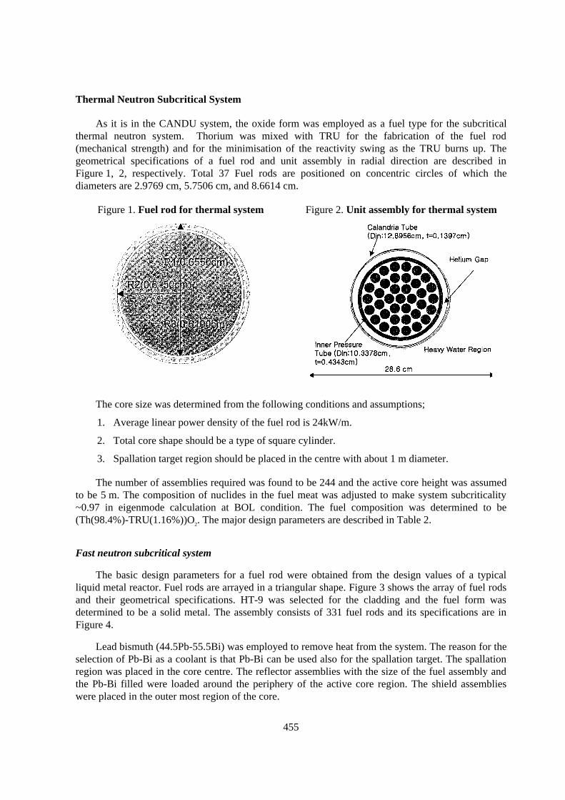
455
Thermal Neutron Subcritical System
As it is in the CANDU system, the oxide form was employed as a fuel type for the subcriticalthermal neutron system. Thorium was mixed with TRU for the fabrication of the fuel rod(mechanical strength) and for the minimisation of the reactivity swing as the TRU burns up. Thegeometrical specifications of a fuel rod and unit assembly in radial direction are described inFigure 1, 2, respectively. Total 37 Fuel rods are positioned on concentric circles of which thediameters are 2.9769 cm, 5.7506 cm, and 8.6614 cm.
Figure 1. Fuel rod for thermal system Figure 2. Unit assembly for thermal system
The core size was determined from the following conditions and assumptions;
1. Average linear power density of the fuel rod is 24kW/m.
2. Total core shape should be a type of square cylinder.
3. Spallation target region should be placed in the centre with about 1 m diameter.
The number of assemblies required was found to be 244 and the active core height was assumedto be 5 m. The composition of nuclides in the fuel meat was adjusted to make system subcriticality~0.97 in eigenmode calculation at BOL condition. The fuel composition was determined to be(Th(98.4%)-TRU(1.16%))O2. The major design parameters are described in Table 2.
Fast neutron subcritical system
The basic design parameters for a fuel rod were obtained from the design values of a typicalliquid metal reactor. Fuel rods are arrayed in a triangular shape. Figure 3 shows the array of fuel rodsand their geometrical specifications. HT-9 was selected for the cladding and the fuel form wasdetermined to be a solid metal. The assembly consists of 331 fuel rods and its specifications are inFigure 4.
Lead bismuth (44.5Pb-55.5Bi) was employed to remove heat from the system. The reason for theselection of Pb-Bi as a coolant is that Pb-Bi can be used also for the spallation target. The spallationregion was placed in the core centre. The reflector assemblies with the size of the fuel assembly andthe Pb-Bi filled were loaded around the periphery of the active core region. The shield assemblieswere placed in the outer most region of the core.
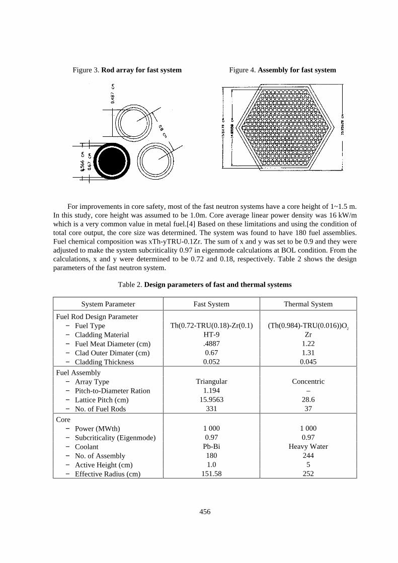
456
Figure 3. Rod array for fast system Figure 4. Assembly for fast system
For improvements in core safety, most of the fast neutron systems have a core height of 1~1.5 m.In this study, core height was assumed to be 1.0m. Core average linear power density was 16 kW/mwhich is a very common value in metal fuel.[4] Based on these limitations and using the condition oftotal core output, the core size was determined. The system was found to have 180 fuel assemblies.Fuel chemical composition was xTh-yTRU-0.1Zr. The sum of x and y was set to be 0.9 and they wereadjusted to make the system subcriticality 0.97 in eigenmode calculations at BOL condition. From thecalculations, x and y were determined to be 0.72 and 0.18, respectively. Table 2 shows the designparameters of the fast neutron system.
Table 2. Design parameters of fast and thermal systems
System Parameter Fast System Thermal System
Fuel Rod Design Parameter− Fuel Type Th(0.72-TRU(0.18)-Zr(0.1) (Th(0.984)-TRU(0.016))O2
− Cladding Material HT-9 Zr− Fuel Meat Diameter (cm) .4887 1.22− Clad Outer Dimater (cm) 0.67 1.31− Cladding Thickness 0.052 0.045
Fuel Assembly− Array Type Triangular Concentric− Pitch-to-Diameter Ration 1.194 –− Lattice Pitch (cm) 15.9563 28.6− No. of Fuel Rods 331 37
Core− Power (MWth) 1 000 1 000− Subcriticality (Eigenmode) 0.97 0.97− Coolant Pb-Bi Heavy Water− No. of Assembly 180 244− Active Height (cm) 1.0 5− Effective Radius (cm) 151.58 252
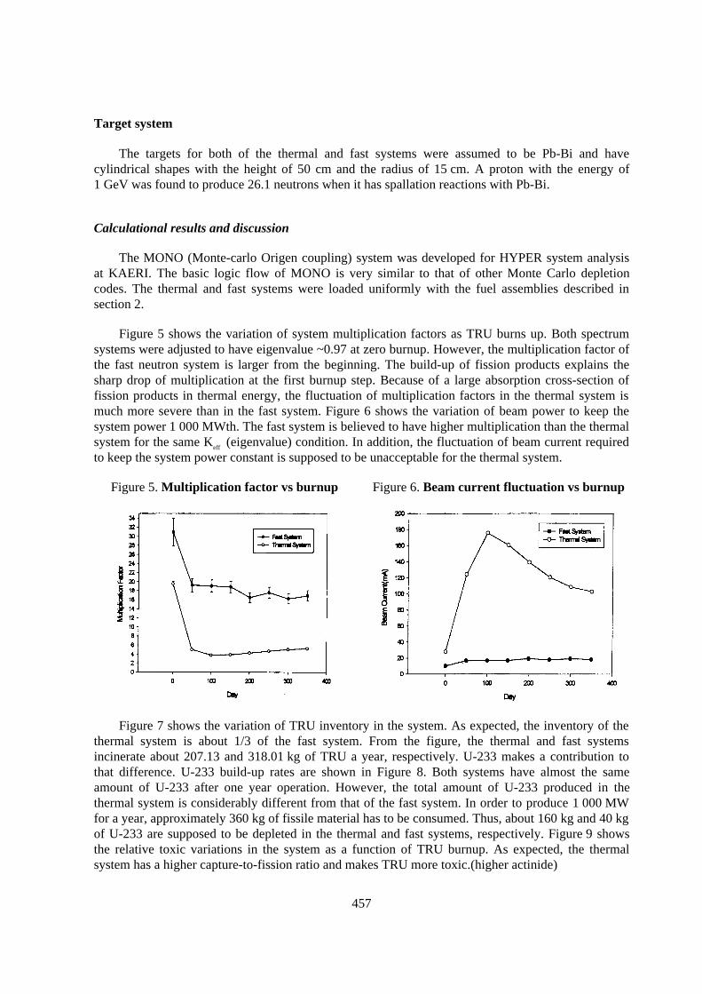
457
Target system
The targets for both of the thermal and fast systems were assumed to be Pb-Bi and havecylindrical shapes with the height of 50 cm and the radius of 15 cm. A proton with the energy of1 GeV was found to produce 26.1 neutrons when it has spallation reactions with Pb-Bi.
Calculational results and discussion
The MONO (Monte-carlo Origen coupling) system was developed for HYPER system analysisat KAERI. The basic logic flow of MONO is very similar to that of other Monte Carlo depletioncodes. The thermal and fast systems were loaded uniformly with the fuel assemblies described insection 2.
Figure 5 shows the variation of system multiplication factors as TRU burns up. Both spectrumsystems were adjusted to have eigenvalue ~0.97 at zero burnup. However, the multiplication factor ofthe fast neutron system is larger from the beginning. The build-up of fission products explains thesharp drop of multiplication at the first burnup step. Because of a large absorption cross-section offission products in thermal energy, the fluctuation of multiplication factors in the thermal system ismuch more severe than in the fast system. Figure 6 shows the variation of beam power to keep thesystem power 1 000 MWth. The fast system is believed to have higher multiplication than the thermalsystem for the same Keff (eigenvalue) condition. In addition, the fluctuation of beam current requiredto keep the system power constant is supposed to be unacceptable for the thermal system.
Figure 5. Multiplication factor vs burnup Figure 6. Beam current fluctuation vs burnup
Figure 7 shows the variation of TRU inventory in the system. As expected, the inventory of thethermal system is about 1/3 of the fast system. From the figure, the thermal and fast systemsincinerate about 207.13 and 318.01 kg of TRU a year, respectively. U-233 makes a contribution tothat difference. U-233 build-up rates are shown in Figure 8. Both systems have almost the sameamount of U-233 after one year operation. However, the total amount of U-233 produced in thethermal system is considerably different from that of the fast system. In order to produce 1 000 MWfor a year, approximately 360 kg of fissile material has to be consumed. Thus, about 160 kg and 40 kgof U-233 are supposed to be depleted in the thermal and fast systems, respectively. Figure 9 showsthe relative toxic variations in the system as a function of TRU burnup. As expected, the thermalsystem has a higher capture-to-fission ratio and makes TRU more toxic.(higher actinide)
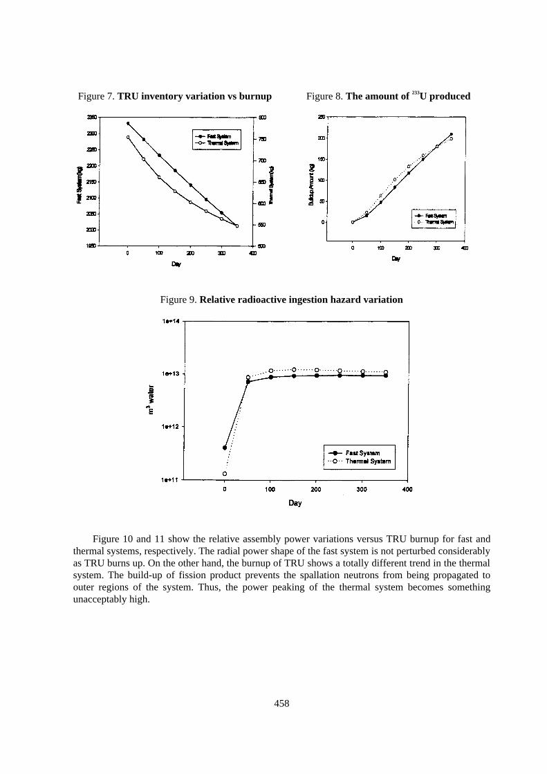
458
Figure 7. TRU inventory variation vs burnup Figure 8. The amount of 233U produced
Figure 9. Relative radioactive ingestion hazard variation
Figure 10 and 11 show the relative assembly power variations versus TRU burnup for fast andthermal systems, respectively. The radial power shape of the fast system is not perturbed considerablyas TRU burns up. On the other hand, the burnup of TRU shows a totally different trend in the thermalsystem. The build-up of fission product prevents the spallation neutrons from being propagated toouter regions of the system. Thus, the power peaking of the thermal system becomes somethingunacceptably high.
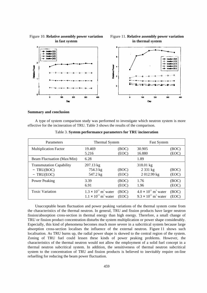
459
Figure 10. Relative assembly power variationin fast system
Figure 11. Relative assembly power variationin thermal system
Summary and conclusion
A type of system comparison study was performed to investigate which neutron system is moreeffective for the incineration of TRU. Table 3 shows the results of the comparison.
Table 3. System performance parameters for TRU incineration
Parameters Thermal System Fast System
Multiplication Factor 19.469 (BOC) 30.905 (BOC)5.216 (EOC) 16.880 (EOC)
Beam Fluctuation (Max/Min) 6.28 1.89
Transmutation Capability 207.13 kg 318.01 kg− TRU(BOC) 754.3 kg (BOC) 2 331 kg (BOC)− TRU(EOC) 547.2 kg (EOC) 2 012.99 kg (EOC)
Power Peaking 3.39 (BOC) 1.76 (BOC)6.91 (EOC) 1.96 (EOC)
Toxic Variation 1.3 × 10¹¹ m3 water (BOC) 4.0 × 10¹¹ m3 water (BOC)1.1 × 10¹³ m3 water (EOC) 9.3 × 10¹² m3 water (EOC)
Unacceptable beam fluctuation and power peaking variations of the thermal system come fromthe characteristics of the thermal neutron. In general, TRU and fission products have larger neutronfission/absorption cross-section in thermal energy than high energy. Therefore, a small change ofTRU or fission product concentration disturbs the system multiplication or power shape considerably.Especially, this kind of phenomena becomes much more severe in a subcritical system because largeabsorption cross-section localises the influence of the external neutron. Figure 11 shows suchlocalisation. As TRU burns up, the radial power shape is skewed to the central region of the system.Zoning of TRU fuel could lessen these kinds of power peaking problems. However, thecharacteristics of the thermal neutron would not allow the employment of a solid fuel concept in athermal neutron subcritical system. In addition, the sensitiveness of thermal neutron subcriticalsystem to the concentration of TRU and fission products is believed to inevitably require on-linerefuelling for reducing the beam power fluctuation.
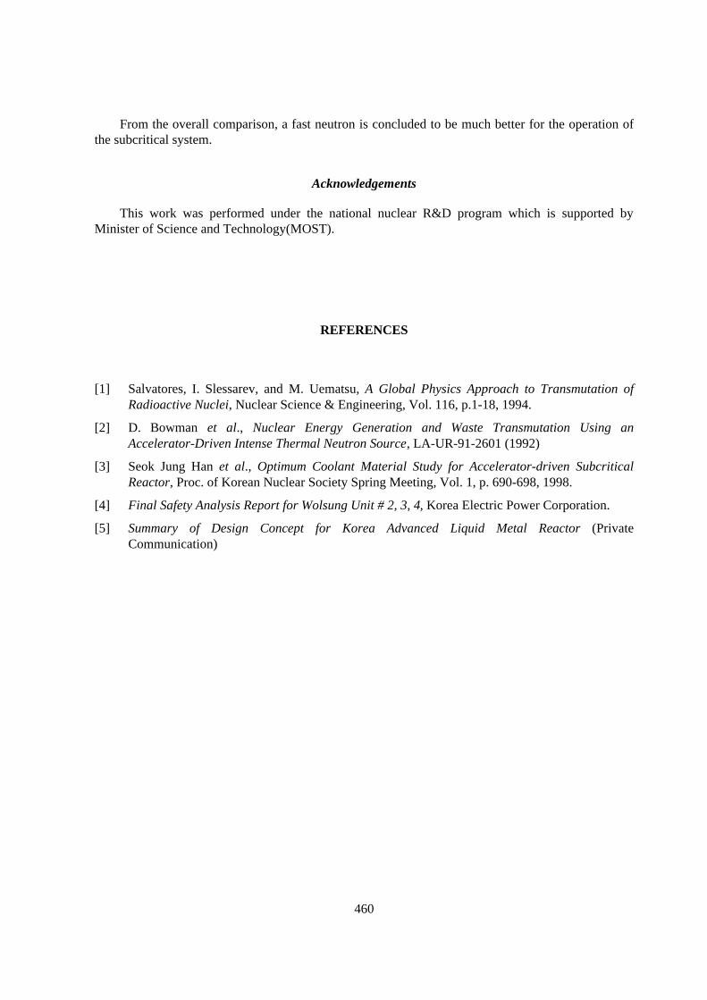
460
From the overall comparison, a fast neutron is concluded to be much better for the operation ofthe subcritical system.
Acknowledgements
This work was performed under the national nuclear R&D program which is supported byMinister of Science and Technology(MOST).
REFERENCES
[1] Salvatores, I. Slessarev, and M. Uematsu, A Global Physics Approach to Transmutation ofRadioactive Nuclei, Nuclear Science & Engineering, Vol. 116, p.1-18, 1994.
[2] D. Bowman et al., Nuclear Energy Generation and Waste Transmutation Using anAccelerator-Driven Intense Thermal Neutron Source, LA-UR-91-2601 (1992)
[3] Seok Jung Han et al., Optimum Coolant Material Study for Accelerator-driven SubcriticalReactor, Proc. of Korean Nuclear Society Spring Meeting, Vol. 1, p. 690-698, 1998.
[4] Final Safety Analysis Report for Wolsung Unit # 2, 3, 4, Korea Electric Power Corporation.
[5] Summary of Design Concept for Korea Advanced Liquid Metal Reactor (PrivateCommunication)