an accelerator driven system myrrha - welcome to the … · • needed for transmutation: ......
TRANSCRIPT
1
An Accelerator Driven System MYRRHA
Dirk Vandeplassche
CERN Accelerator School Bruges, June 20, 2009
2
global framework
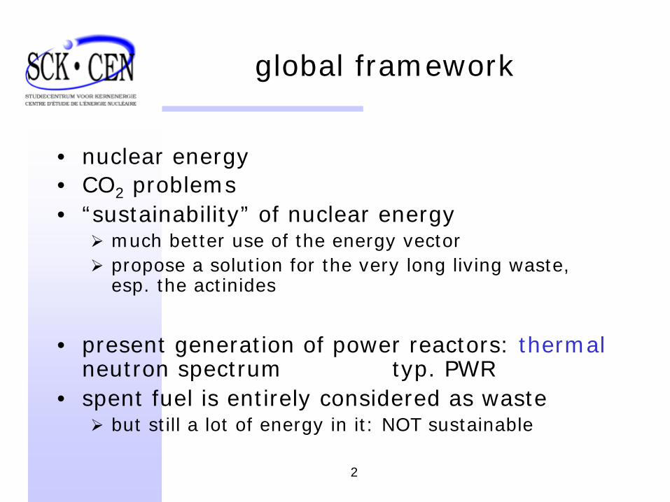
• nuclear energy• CO2 problems• “sustainability” of nuclear energy
much better use of the energy vectorpropose a solution for the very long living waste, esp. the actinides
• present generation of power reactors: thermal neutron spectrum typ. PWR
• spent fuel is entirely considered as wastebut still a lot of energy in it: NOT sustainable
3
global framework
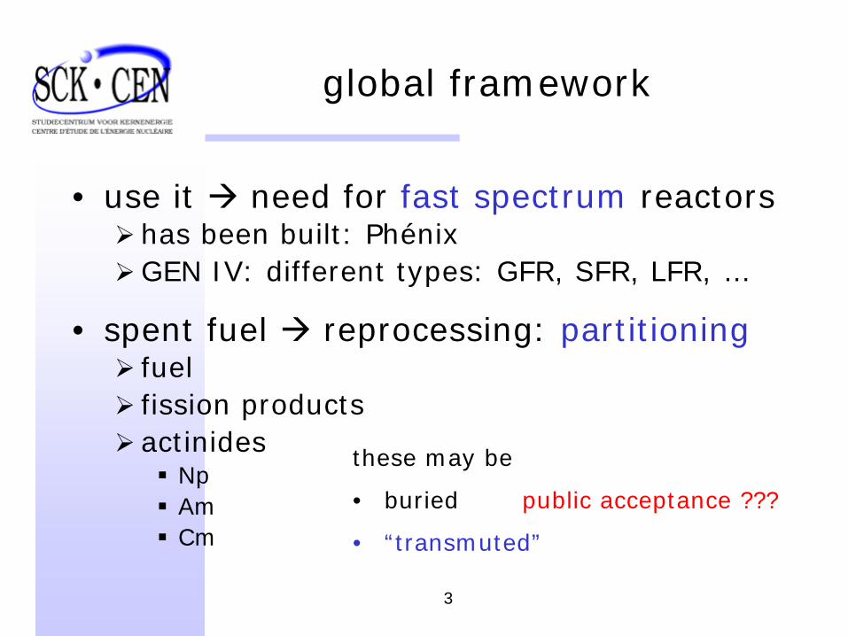
• use it need for fast spectrum reactorshas been built: PhénixGEN IV: different types: GFR, SFR, LFR, …
• spent fuel reprocessing: partitioningfuelfission productsactinides
NpAmCm
these may be
• buried public acceptance ???
• “transmuted”
4
global framework
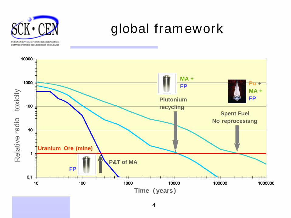
Plutonium recycling
Spent FuelNo reprocesisng
Uranium Ore (mine)
Time ( years )
Rel
ativ
e ra
dio
toxi
city
P&T of MA
Pu +MA +FP
MA +FP
FP
5
global framework
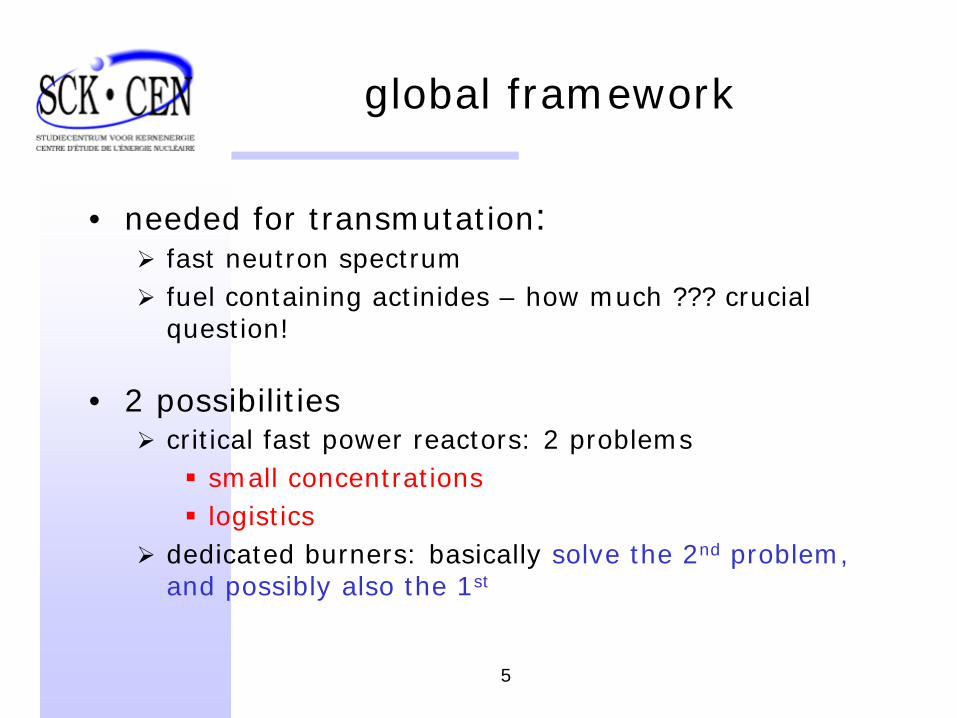
• needed for transmutation:fast neutron spectrumfuel containing actinides – how much ??? crucial question!
• 2 possibilitiescritical fast power reactors: 2 problems
small concentrationslogistics
dedicated burners: basically solve the 2nd problem, and possibly also the 1st
6
global framework
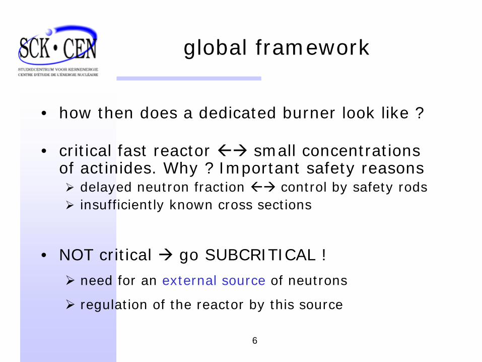
• how then does a dedicated burner look like ?
• critical fast reactor small concentrations of actinides. Why ? Important safety reasons
delayed neutron fraction control by safety rodsinsufficiently known cross sections
• NOT critical go SUBCRITICAL !
need for an external source of neutrons
regulation of the reactor by this source
7
global framework
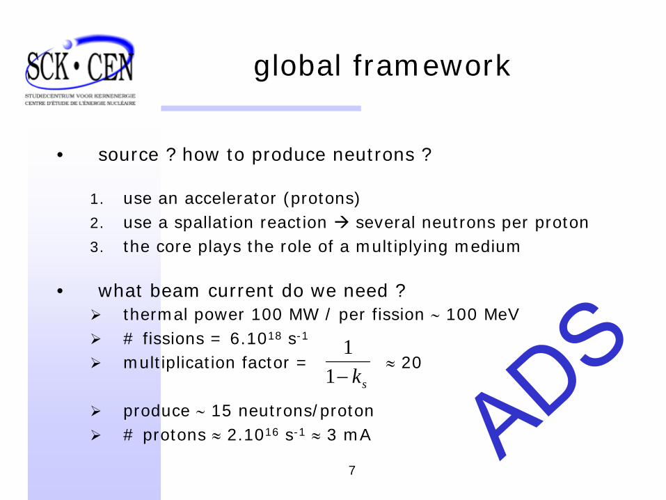
• source ? how to produce neutrons ?
1. use an accelerator (protons)2. use a spallation reaction several neutrons per proton3. the core plays the role of a multiplying medium
• what beam current do we need ?thermal power 100 MW / per fission ∼ 100 MeV# fissions = 6.1018 s-1
multiplication factor = ≈ 20
produce ∼ 15 neutrons/proton# protons ≈ 2.1016 s-1 ≈ 3 mA
sk−11
8
SCK CEN
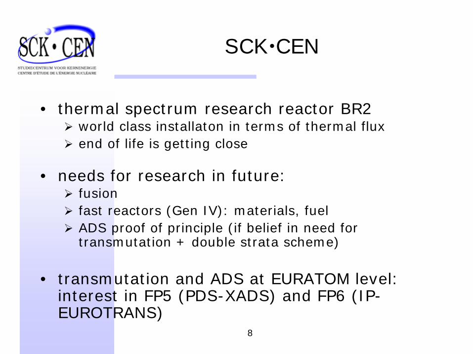
• thermal spectrum research reactor BR2world class installaton in terms of thermal fluxend of life is getting close
• needs for research in future:fusionfast reactors (Gen IV): materials, fuelADS proof of principle (if belief in need for transmutation + double strata scheme)
• transmutation and ADS at EURATOM level: interest in FP5 (PDS-XADS) and FP6 (IP- EUROTRANS)
9
SCK CEN
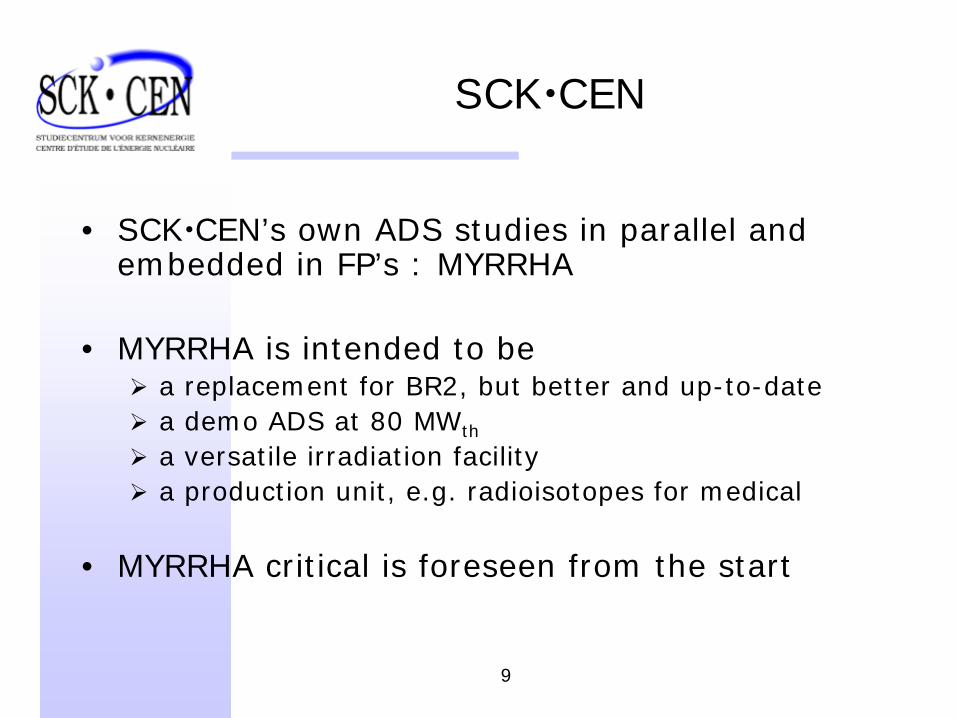
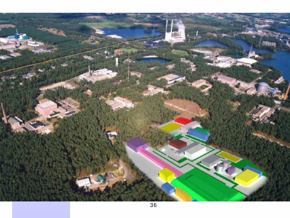
• SCK CEN’s own ADS studies in parallel and embedded in FP’s : MYRRHA
• MYRRHA is intended to bea replacement for BR2, but better and up-to-datea demo ADS at 80 MWth
a versatile irradiation facilitya production unit, e.g. radioisotopes for medical
• MYRRHA critical is foreseen from the start
10
MYRRHA system description
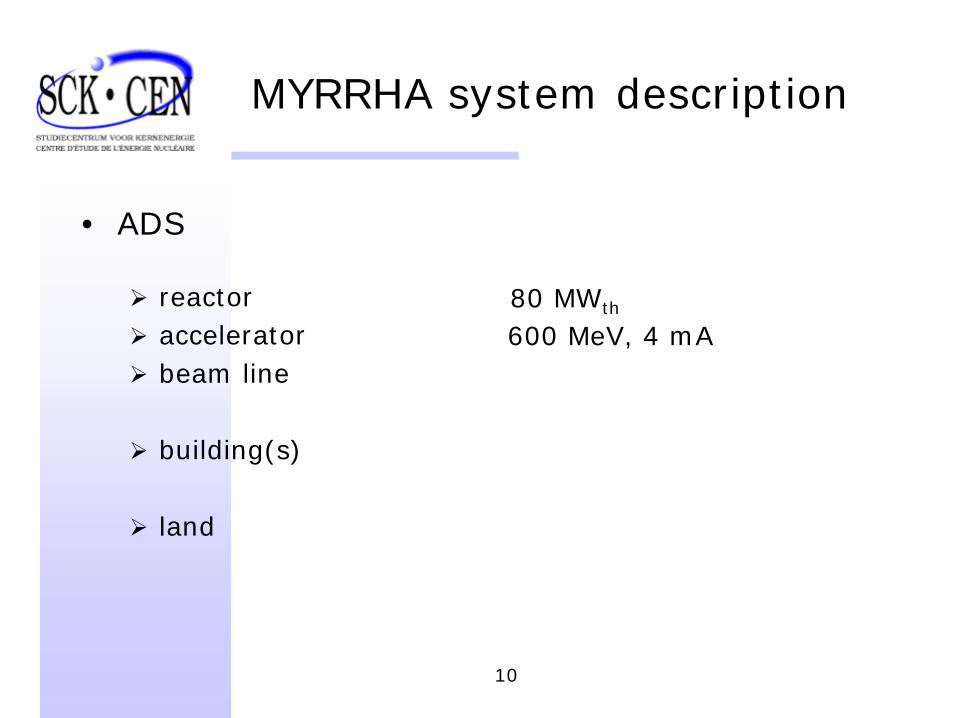
• ADS
reactoracceleratorbeam line
building(s)
land
80 MWth
600 MeV, 4 mA
11
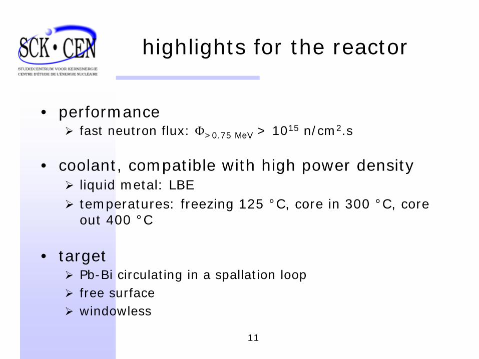
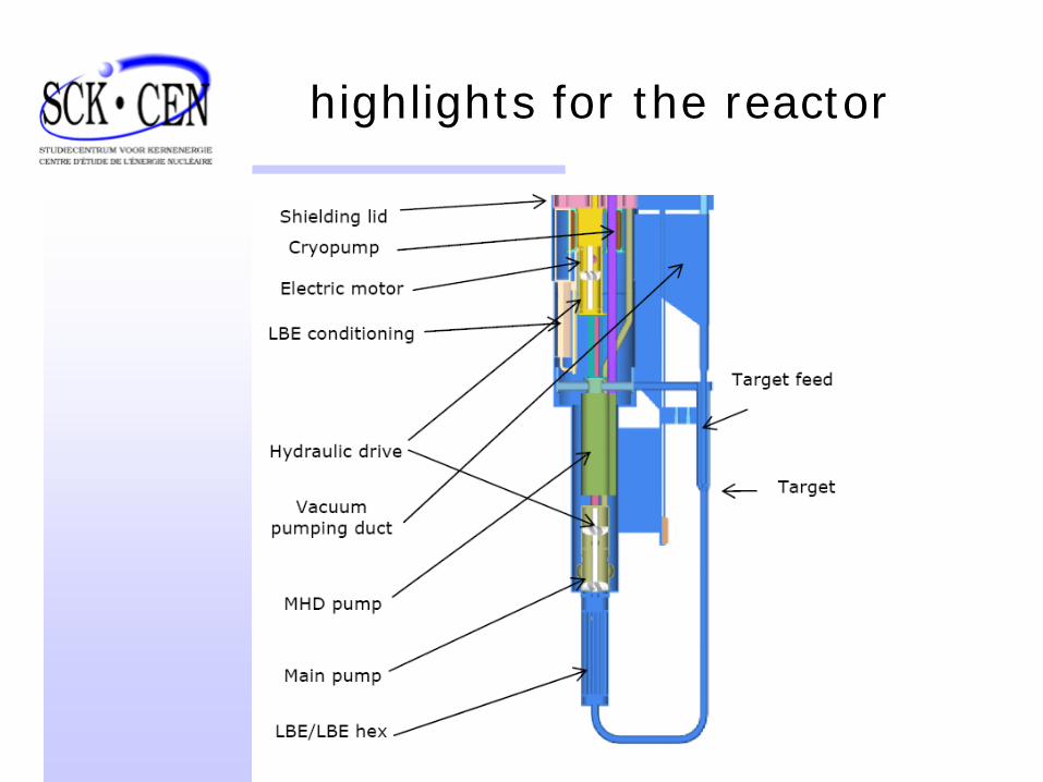
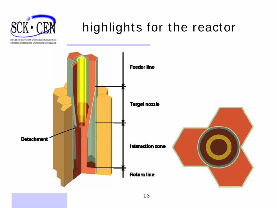
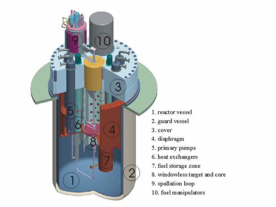
highlights for the reactor
• performancefast neutron flux: Φ>0.75 MeV > 1015 n/cm2.s
• coolant, compatible with high power densityliquid metal: LBEtemperatures: freezing 125 °C, core in 300 °C, core out 400 °C
• targetPb-Bi circulating in a spallation loopfree surfacewindowless
12
highlights for the reactor
13
highlights for the reactor
14
15
highlights for the reactor
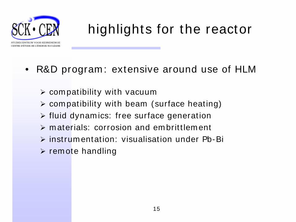
• R&D program: extensive around use of HLM
compatibility with vacuumcompatibility with beam (surface heating)fluid dynamics: free surface generationmaterials: corrosion and embrittlementinstrumentation: visualisation under Pb-Biremote handling
16
The accelerator
• performances for Myrrhasee tablechallenging: CW reliability/availability
special requirements on reliability:beam trip > 1s = failurefailure frequency < ∼1/monthor: MTBF ≈ 500 h (typical 20 – best 100 h ?)
• principles for increased reliabilitydownrating, ample operational marginsredundancy: parallel vs. serial scheme
17
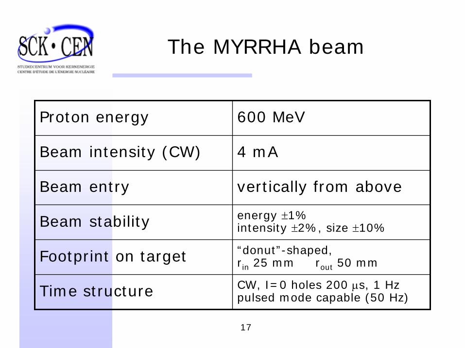
The MYRRHA beam
Proton energy 600 MeV
Beam intensity (CW) 4 mA
Beam entry vertically from above
Beam stability energy ±1%intensity ±2%, size ±10%
Footprint on target “donut”-shaped,rin 25 mm rout 50 mm
Time structure CW, I=0 holes 200 μs, 1 Hzpulsed mode capable (50 Hz)
18
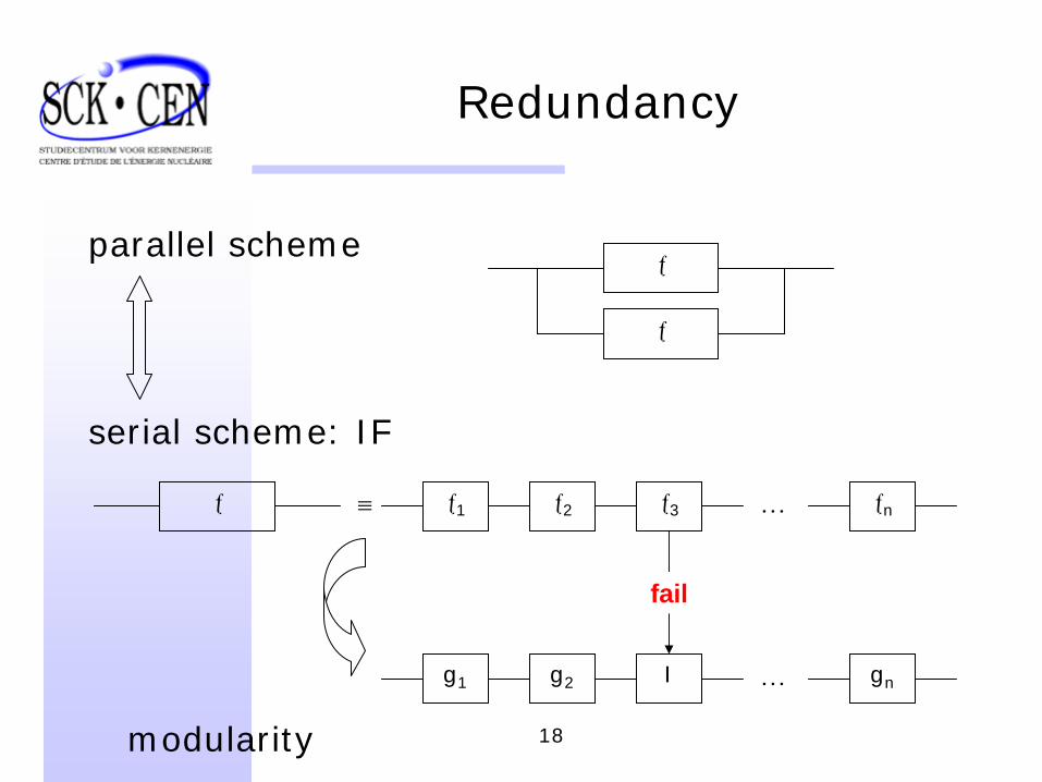
Redundancy
parallel scheme
serial scheme: IF
ƒ
ƒ
ƒ ≡ …ƒ1 ƒ2 ƒ3 ƒn
…Ig1 g2 gn
fail
modularity
19
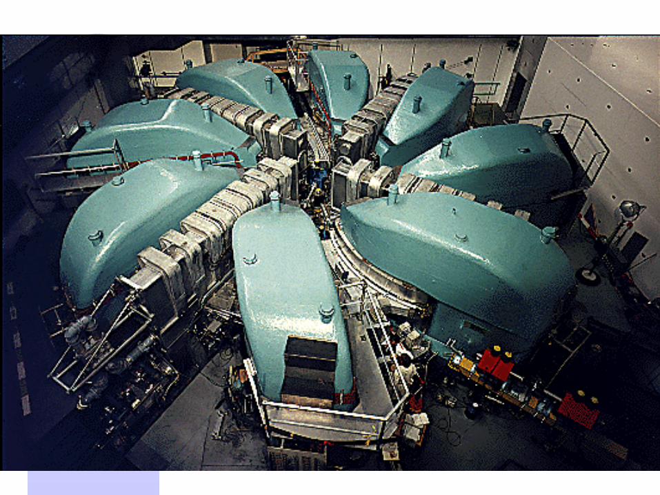
Choice of accelerator type
• CW beam 1. cyclotron: naturally CW (isochronous), but “at the
limits”2. linac: “straightforward” for performances, mostly
pulsed3. (FFAG)
• fundamental differences:monolithic modularextraction “not an issue”, beam quality∼fixed flexible and expandable
20
21
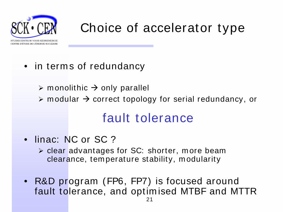
Choice of accelerator type
• in terms of redundancy
monolithic only parallelmodular correct topology for serial redundancy, or
fault tolerance
• linac: NC or SC ?clear advantages for SC: shorter, more beam clearance, temperature stability, modularity
• R&D program (FP6, FP7) is focused around fault tolerance, and optimised MTBF and MTTR
22
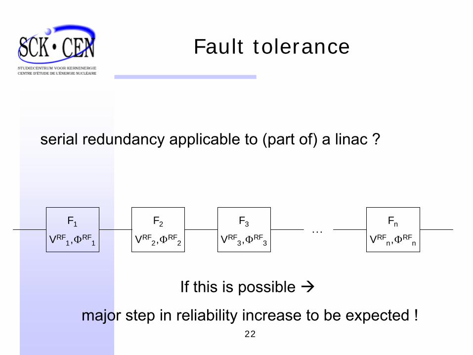
Fault tolerance
serial redundancy applicable to (part of) a linac ?
…F1
VRF1 ,ΦRF
1
F2
VRF2 ,ΦRF
2
F3
VRF3 ,ΦRF
3
Fn
VRFn ,ΦRF
n
If this is possible
major step in reliability increase to be expected !
23
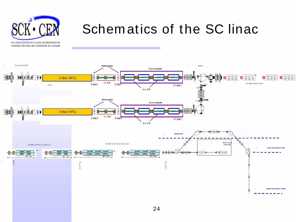
Schematics of the SC linac
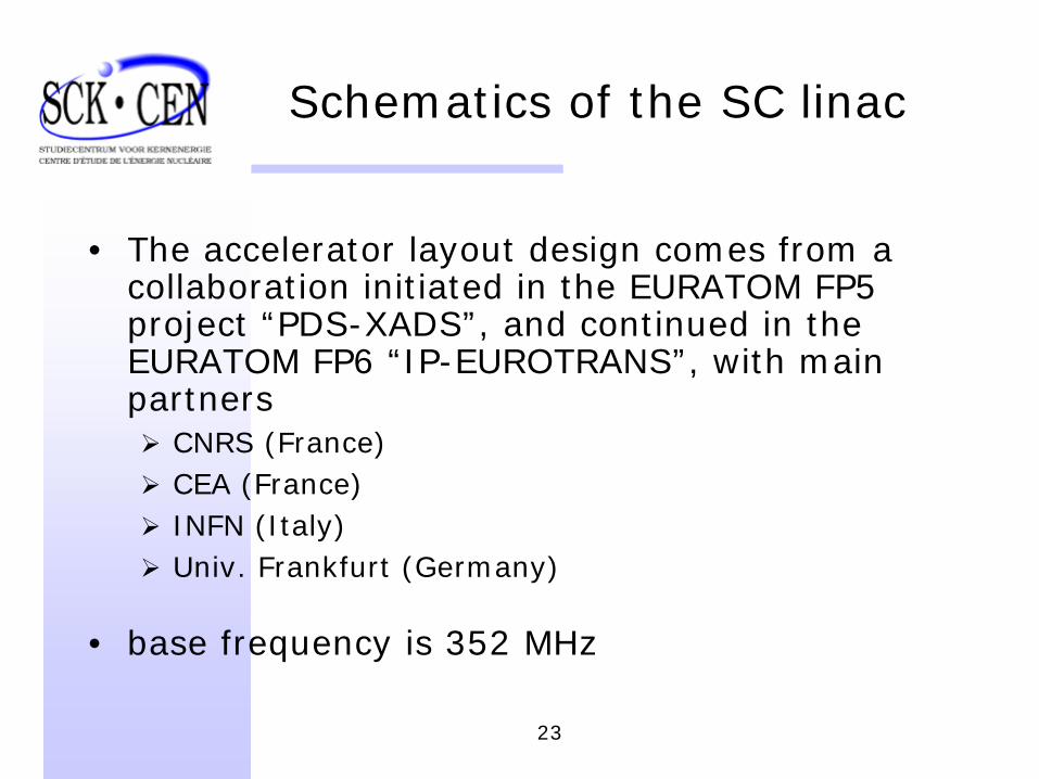
• The accelerator layout design comes from a collaboration initiated in the EURATOM FP5 project “PDS-XADS”, and continued in the EURATOM FP6 “IP-EUROTRANS”, with main partners
CNRS (France)CEA (France)INFN (Italy)Univ. Frankfurt (Germany)
• base frequency is 352 MHz
24
• Ion source & LEBT
• 50 keV
• MEBT
•
...
• 352 MHz SPOKE LINAC
•
Earth level
•
linac level (about -5m)
•
target level (about -30m)
•
Beam
dump casemate
•
... •
...
• 704 MHz ELIPTICAL LINAC 0.5 • 704 MHz ELIPTICAL LINAC 0.65
• 90 M eV
• 20 0 M eV
• 60 0 M eV
Schematics of the SC linac
25
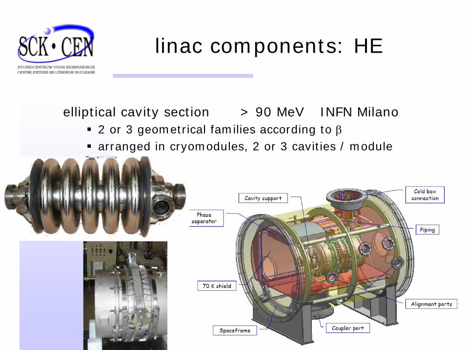
linac components: HE
elliptical cavity section > 90 MeV INFN Milano2 or 3 geometrical families according to βarranged in cryomodules, 2 or 3 cavities / module
26
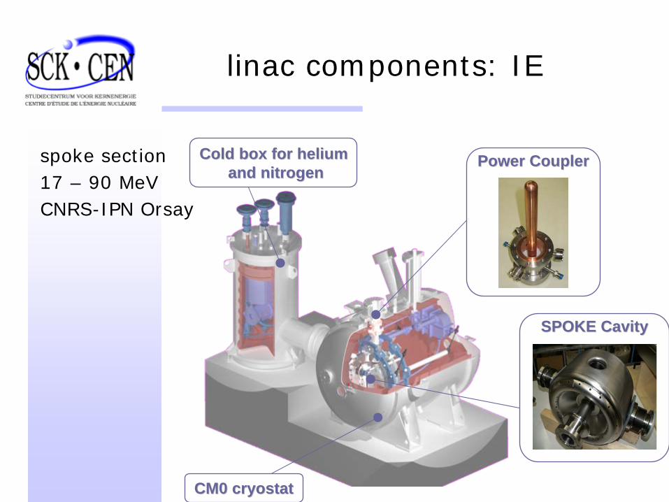
linac components: IE
SPOKE CavitySPOKE Cavity
Cold box for heliumCold box for heliumand nitrogenand nitrogen
CM0 cryostatCM0 cryostat
Power CouplerPower Couplerspoke section17 – 90 MeVCNRS-IPN Orsay
27
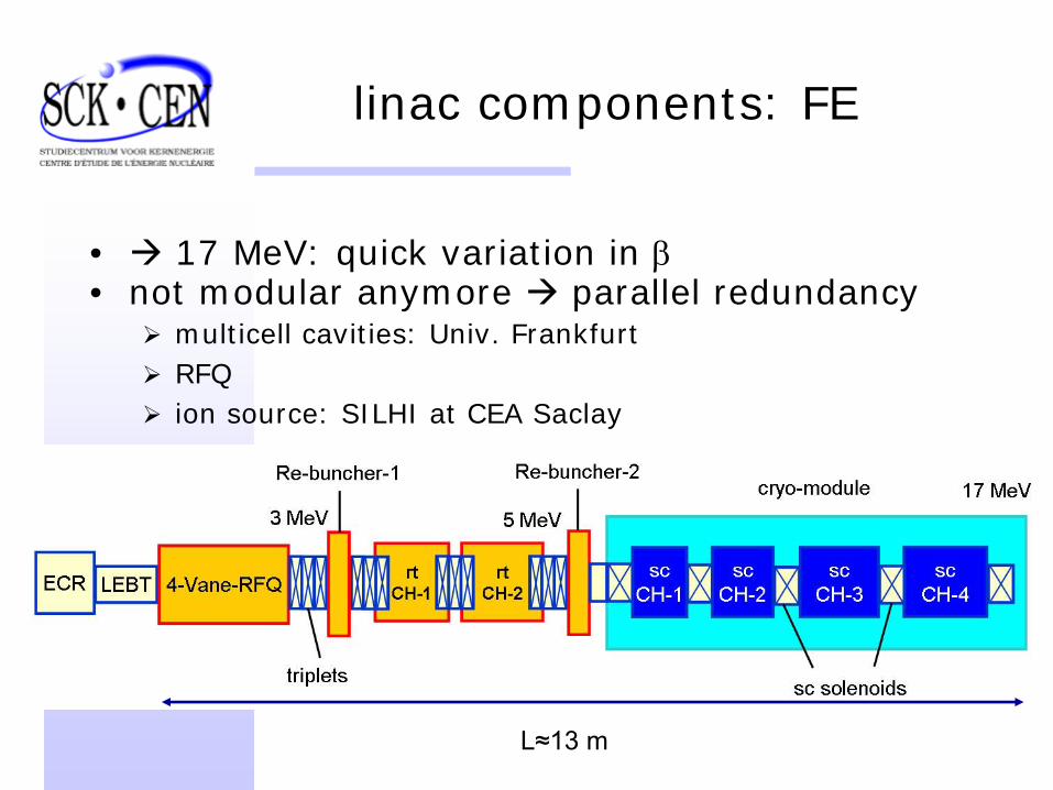
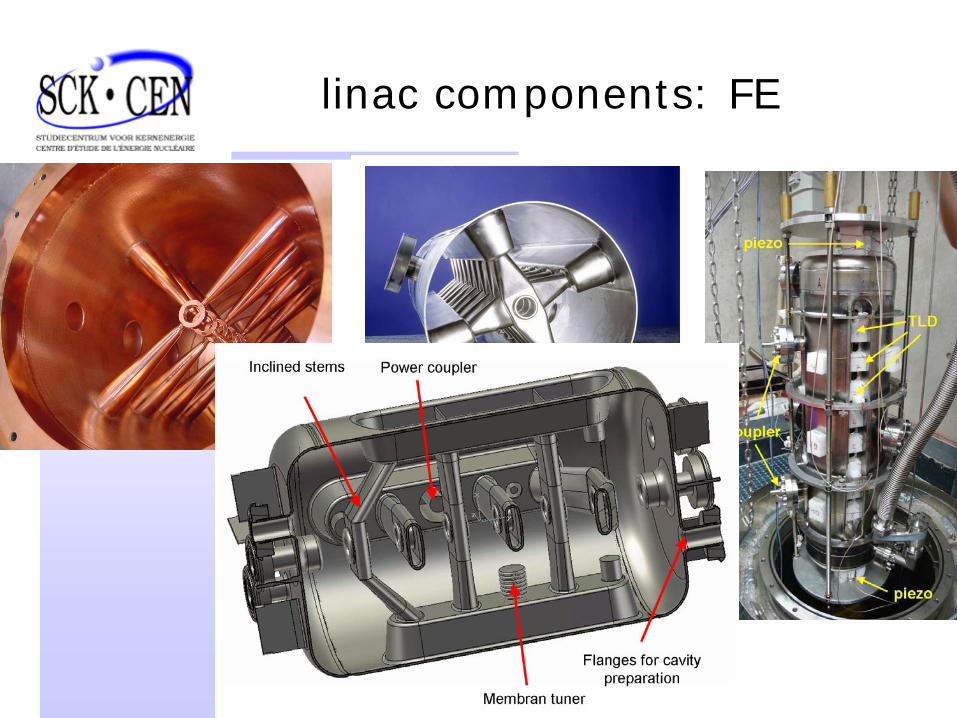
linac components: FE
• 17 MeV: quick variation in β• not modular anymore parallel redundancy
multicell cavities: Univ. FrankfurtRFQion source: SILHI at CEA Saclay
L≈13 m
28
linac components: FE
29
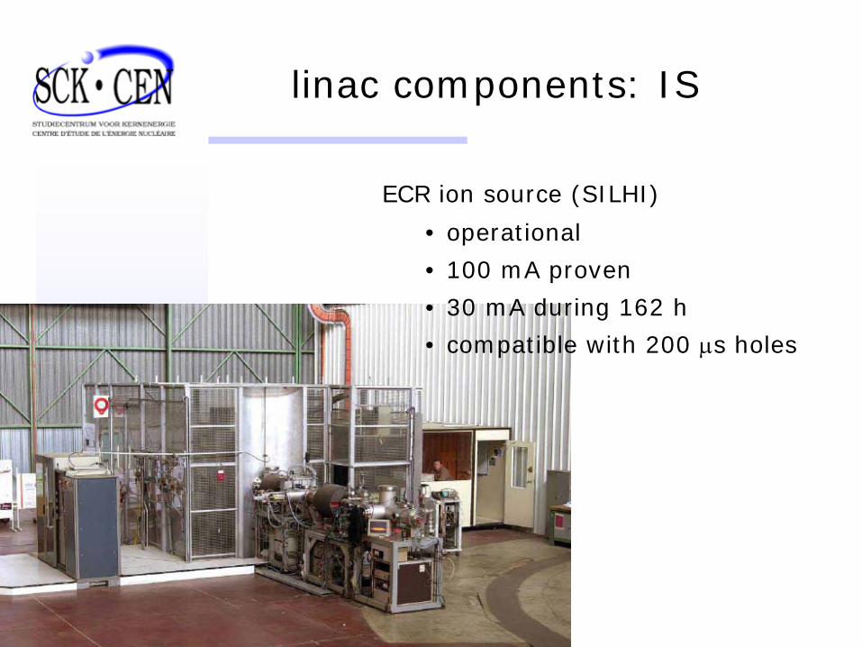
linac components: IS
ECR ion source (SILHI)
• operational
• 100 mA proven
• 30 mA during 162 h
• compatible with 200 μs holes
30
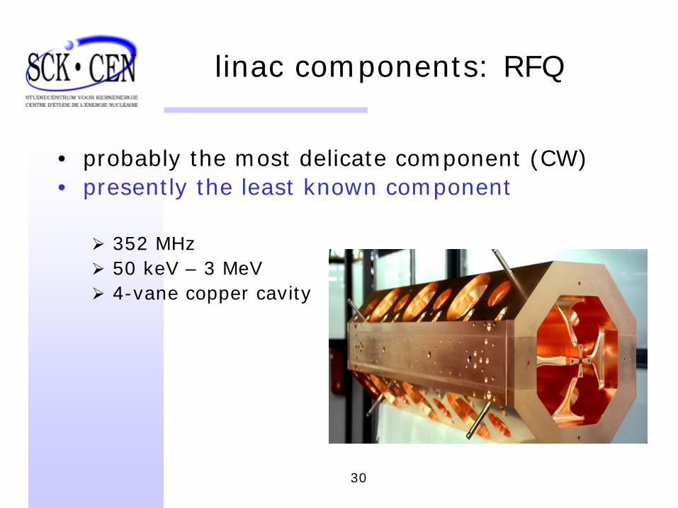
linac components: RFQ
• probably the most delicate component (CW)• presently the least known component
352 MHz50 keV – 3 MeV4-vane copper cavity
31
Fault tolerance issues
• the schemeglobal shown to work at SNSlocal OK in simulations, with typ. 4
surrounding cavities
• the scenariofault detectionswitch off beamdetune faulty cavityretune neighbour cavities, < tablesreinject beam
< 1 s
32
Fault tolerance issues
• the toolsLLRF, entirely based on fast digital programmable componentstests with prototypes are foreseen on cold cavities
• reliability model studies
33
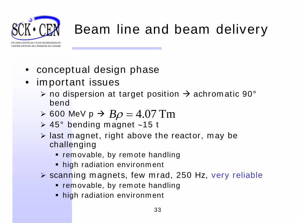
Beam line and beam delivery
• conceptual design phase• important issues
no dispersion at target position achromatic 90°bend600 MeV p 45° bending magnet ∼15 tlast magnet, right above the reactor, may be challenging
removable, by remote handlinghigh radiation environment
scanning magnets, few mrad, 250 Hz, very reliableremovable, by remote handlinghigh radiation environment
Tm 07.4=ρB
34
Conclusion
• if sustainable nuclear energy is chosen by society as one of the pillars for satisfying future energy demands, then transmutation and partitioning are fundamental ingredients
• if a double strata scenario is privileged, then ADS is the technology to apply
• there is presently a relatively cool but worldwide interest in ADS
35
Conclusion
• at SCK CEN we consider that research in this domain is useful and necessary, and that a research irradiation facility based on ADS technology is the logical next step, and one giving many new possibilities in its field
Myrrha project
• the accelerator physicist’s standpoint: the development of high reliability accelerators is a necessity for all future applications, both in research and in industry
36