a framework for asynchronous circuit modeling … framework for asynchronous circuit modeling and...
TRANSCRIPT
A Framework for Asynchronous Circuit Modeling andVerification in ACL2
Cuong Chau1, Warren A. Hunt, Jr.1,Marly Roncken2, and Ivan Sutherland2
{ckcuong,hunt}@cs.utexas.edu,[email protected], [email protected]
1 The University of Texas at Austin2 Portland State University
November 14, 2017
Chau et al. (UT Austin, PSU) Asynchronous Circuit Verification November 14, 2017 1 / 26

Outline
1 Introduction
2 The DE System
3 Modeling and Verification Approach
4 32-Bit Self-Timed Serial Adder Verification
5 Future Work and Conclusions
Chau et al. (UT Austin, PSU) Asynchronous Circuit Verification November 14, 2017 2 / 26

Outline
1 Introduction
2 The DE System
3 Modeling and Verification Approach
4 32-Bit Self-Timed Serial Adder Verification
5 Future Work and Conclusions
Chau et al. (UT Austin, PSU) Asynchronous Circuit Verification November 14, 2017 3 / 26

Introduction
Synchronous circuits (or clocked circuits): changes in the state of storageelements are synchronized by a global clock signal.
Asynchronous circuits (or self-timed circuits): no global clock signal. Thecommunications between storage elements are performed via localcommunication protocols.
Why asynchronous?
Low power consumption,High operating speed,Elimination of clock skew problems,Better composability and modularity for large systems,...
Chau et al. (UT Austin, PSU) Asynchronous Circuit Verification November 14, 2017 4 / 26
Introduction
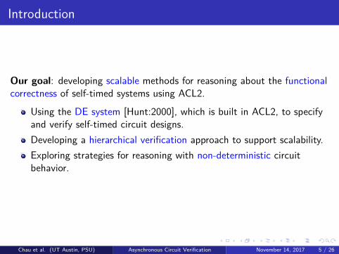
Our goal: developing scalable methods for reasoning about the functionalcorrectness of self-timed systems using ACL2.
Using the DE system [Hunt:2000], which is built in ACL2, to specifyand verify self-timed circuit designs.Developing a hierarchical verification approach to support scalability.Exploring strategies for reasoning with non-deterministic circuitbehavior.
Chau et al. (UT Austin, PSU) Asynchronous Circuit Verification November 14, 2017 5 / 26

Introduction
Our goal: developing scalable methods for reasoning about the functionalcorrectness of self-timed systems using ACL2.
Using the DE system [Hunt:2000], which is built in ACL2, to specifyand verify self-timed circuit designs.
Developing a hierarchical verification approach to support scalability.Exploring strategies for reasoning with non-deterministic circuitbehavior.
Chau et al. (UT Austin, PSU) Asynchronous Circuit Verification November 14, 2017 5 / 26

Introduction
Our goal: developing scalable methods for reasoning about the functionalcorrectness of self-timed systems using ACL2.
Using the DE system [Hunt:2000], which is built in ACL2, to specifyand verify self-timed circuit designs.Developing a hierarchical verification approach to support scalability.
Exploring strategies for reasoning with non-deterministic circuitbehavior.
Chau et al. (UT Austin, PSU) Asynchronous Circuit Verification November 14, 2017 5 / 26
Introduction
Our goal: developing scalable methods for reasoning about the functionalcorrectness of self-timed systems using ACL2.
Using the DE system [Hunt:2000], which is built in ACL2, to specifyand verify self-timed circuit designs.Developing a hierarchical verification approach to support scalability.Exploring strategies for reasoning with non-deterministic circuitbehavior.
Chau et al. (UT Austin, PSU) Asynchronous Circuit Verification November 14, 2017 5 / 26
Outline
1 Introduction
2 The DE System
3 Modeling and Verification Approach
4 32-Bit Self-Timed Serial Adder Verification
5 Future Work and Conclusions
Chau et al. (UT Austin, PSU) Asynchronous Circuit Verification November 14, 2017 6 / 26

The DE SystemDE is a formal occurrence-oriented hardware description languagedeveloped in ACL2 for describing Mealy machines [Hunt:2000].
The DE system supports hierarchical verification:
Prove the following two lemmas hierarchically for each module: avalue lemma specifying the module’s outputs and a state lemmaspecifying the module’s next state.If a module doesn’t have an internal state (purely combinational),only the value lemma need be proven.These lemmas are used to prove the correctness of yet larger modulescontaining these submodules, without the need to dig into anydetails about the submodules.This approach has been demonstrated its scalability to large systems,as shown on contemporary x86 designs at CentaurTechnology [Slobodova et al.:2011].
Chau et al. (UT Austin, PSU) Asynchronous Circuit Verification November 14, 2017 7 / 26
The DE SystemDE is a formal occurrence-oriented hardware description languagedeveloped in ACL2 for describing Mealy machines [Hunt:2000].
The DE system supports hierarchical verification:
Prove the following two lemmas hierarchically for each module: avalue lemma specifying the module’s outputs and a state lemmaspecifying the module’s next state.
If a module doesn’t have an internal state (purely combinational),only the value lemma need be proven.These lemmas are used to prove the correctness of yet larger modulescontaining these submodules, without the need to dig into anydetails about the submodules.This approach has been demonstrated its scalability to large systems,as shown on contemporary x86 designs at CentaurTechnology [Slobodova et al.:2011].
Chau et al. (UT Austin, PSU) Asynchronous Circuit Verification November 14, 2017 7 / 26
The DE SystemDE is a formal occurrence-oriented hardware description languagedeveloped in ACL2 for describing Mealy machines [Hunt:2000].
The DE system supports hierarchical verification:
Prove the following two lemmas hierarchically for each module: avalue lemma specifying the module’s outputs and a state lemmaspecifying the module’s next state.If a module doesn’t have an internal state (purely combinational),only the value lemma need be proven.
These lemmas are used to prove the correctness of yet larger modulescontaining these submodules, without the need to dig into anydetails about the submodules.This approach has been demonstrated its scalability to large systems,as shown on contemporary x86 designs at CentaurTechnology [Slobodova et al.:2011].
Chau et al. (UT Austin, PSU) Asynchronous Circuit Verification November 14, 2017 7 / 26
The DE SystemDE is a formal occurrence-oriented hardware description languagedeveloped in ACL2 for describing Mealy machines [Hunt:2000].
The DE system supports hierarchical verification:
Prove the following two lemmas hierarchically for each module: avalue lemma specifying the module’s outputs and a state lemmaspecifying the module’s next state.If a module doesn’t have an internal state (purely combinational),only the value lemma need be proven.These lemmas are used to prove the correctness of yet larger modulescontaining these submodules, without the need to dig into anydetails about the submodules.
This approach has been demonstrated its scalability to large systems,as shown on contemporary x86 designs at CentaurTechnology [Slobodova et al.:2011].
Chau et al. (UT Austin, PSU) Asynchronous Circuit Verification November 14, 2017 7 / 26
The DE SystemDE is a formal occurrence-oriented hardware description languagedeveloped in ACL2 for describing Mealy machines [Hunt:2000].
The DE system supports hierarchical verification:
Prove the following two lemmas hierarchically for each module: avalue lemma specifying the module’s outputs and a state lemmaspecifying the module’s next state.If a module doesn’t have an internal state (purely combinational),only the value lemma need be proven.These lemmas are used to prove the correctness of yet larger modulescontaining these submodules, without the need to dig into anydetails about the submodules.This approach has been demonstrated its scalability to large systems,as shown on contemporary x86 designs at CentaurTechnology [Slobodova et al.:2011].
Chau et al. (UT Austin, PSU) Asynchronous Circuit Verification November 14, 2017 7 / 26
Outline
1 Introduction
2 The DE System
3 Modeling and Verification Approach
4 32-Bit Self-Timed Serial Adder Verification
5 Future Work and Conclusions
Chau et al. (UT Austin, PSU) Asynchronous Circuit Verification November 14, 2017 8 / 26

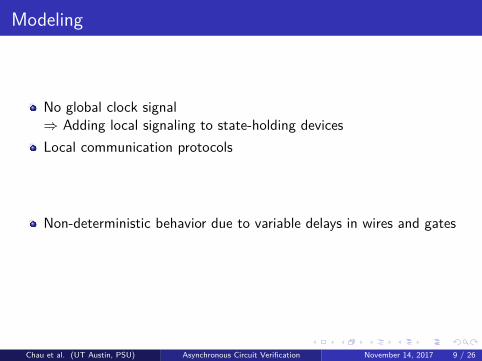
Modeling
No global clock signal
⇒ Adding local signaling to state-holding devices
Local communication protocols
⇒ Modeling the link-joint model introduced by Roncken et al., auniversal communication model for various self-timed circuitfamilies [Roncken et al.:2015]
Non-deterministic behavior due to variable delays in wires and gates
⇒ Employing an oracle, which we call a collection of go signals.These signals are part of the input.
Chau et al. (UT Austin, PSU) Asynchronous Circuit Verification November 14, 2017 9 / 26
Modeling
No global clock signal⇒ Adding local signaling to state-holding devicesLocal communication protocols
⇒ Modeling the link-joint model introduced by Roncken et al., auniversal communication model for various self-timed circuitfamilies [Roncken et al.:2015]
Non-deterministic behavior due to variable delays in wires and gates
⇒ Employing an oracle, which we call a collection of go signals.These signals are part of the input.
Chau et al. (UT Austin, PSU) Asynchronous Circuit Verification November 14, 2017 9 / 26

Modeling
No global clock signal⇒ Adding local signaling to state-holding devicesLocal communication protocols⇒ Modeling the link-joint model introduced by Roncken et al., auniversal communication model for various self-timed circuitfamilies [Roncken et al.:2015]Non-deterministic behavior due to variable delays in wires and gates
⇒ Employing an oracle, which we call a collection of go signals.These signals are part of the input.
Chau et al. (UT Austin, PSU) Asynchronous Circuit Verification November 14, 2017 9 / 26

Modeling
No global clock signal⇒ Adding local signaling to state-holding devicesLocal communication protocols⇒ Modeling the link-joint model introduced by Roncken et al., auniversal communication model for various self-timed circuitfamilies [Roncken et al.:2015]Non-deterministic behavior due to variable delays in wires and gates⇒ Employing an oracle, which we call a collection of go signals.These signals are part of the input.
Chau et al. (UT Austin, PSU) Asynchronous Circuit Verification November 14, 2017 9 / 26

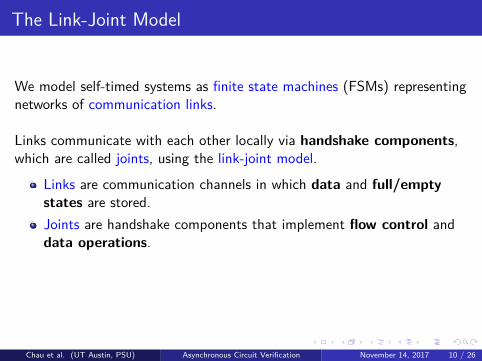
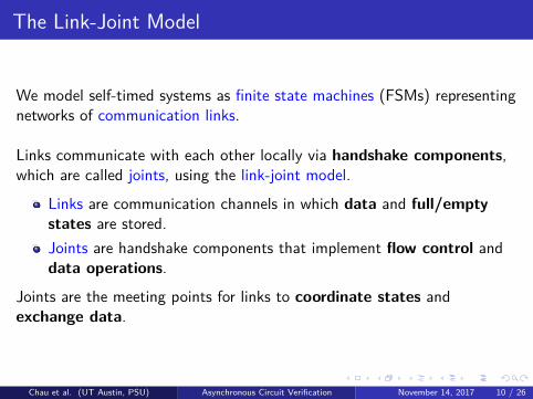
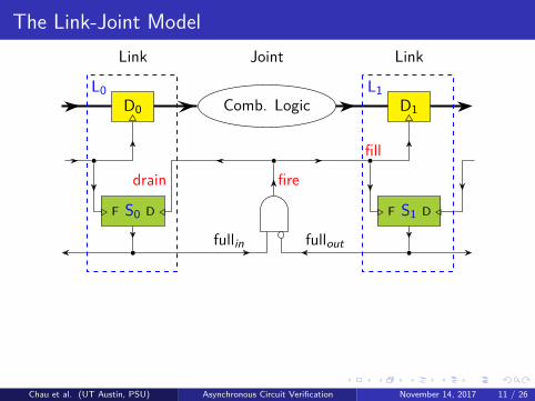
The Link-Joint Model
We model self-timed systems as finite state machines (FSMs) representingnetworks of communication links.
Links communicate with each other locally via handshake components,which are called joints, using the link-joint model.
Links are communication channels in which data and full/emptystates are stored.Joints are handshake components that implement flow control anddata operations.
Joints are the meeting points for links to coordinate states andexchange data.
Chau et al. (UT Austin, PSU) Asynchronous Circuit Verification November 14, 2017 10 / 26
The Link-Joint Model
D0
S0. F D /
fullin
Comb. Logic
firedrain
D1
S1. F D /
fill
fullout
JointLink Link
L0 L1
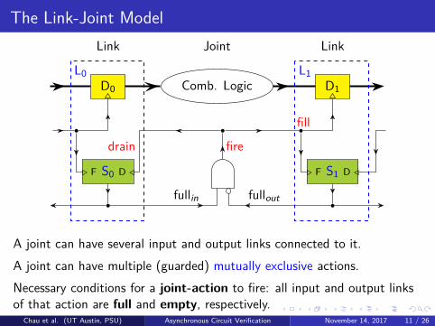
GOA joint can have several input and output links connected to it.A joint can have multiple (guarded) mutually exclusive actions.Necessary conditions for a joint-action to fire: all input and output linksof that action are full and empty, respectively.
Chau et al. (UT Austin, PSU) Asynchronous Circuit Verification November 14, 2017 11 / 26
The Link-Joint Model
D0
S0. F D /
fullin
Comb. Logic
firedrain
D1
S1. F D /
fill
fullout
JointLink Link
L0 L1
GO
A joint can have several input and output links connected to it.A joint can have multiple (guarded) mutually exclusive actions.Necessary conditions for a joint-action to fire: all input and output linksof that action are full and empty, respectively.
Chau et al. (UT Austin, PSU) Asynchronous Circuit Verification November 14, 2017 11 / 26

The Link-Joint Model
D0
S0. F D /
fullin
Comb. Logic
firedrain
D1
S1. F D /
fill
fullout
JointLink Link
L0 L1
GOA joint can have several input and output links connected to it.A joint can have multiple (guarded) mutually exclusive actions.Necessary conditions for a joint-action to fire: all input and output linksof that action are full and empty, respectively.
Chau et al. (UT Austin, PSU) Asynchronous Circuit Verification November 14, 2017 11 / 26
The Link-Joint Model
fullin0...fullinm
...
GO
fullout0...fulloutn
...
drain0 ...drainm
fill0...filln
Comb. LogicDin0...Dinm
Dout0...Doutn
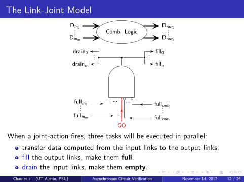
When a joint-action fires, three tasks will be executed in parallel:transfer data computed from the input links to the output links,fill the output links, make them full,drain the input links, make them empty.
Chau et al. (UT Austin, PSU) Asynchronous Circuit Verification November 14, 2017 12 / 26

Verification
Hierarchical reasoning:
The output and next state of a module are formalized using theformalized outputs and next states of submodules, without delvinginto details about the submodules.Self-timed modules can be abstracted as “complex” links or“complex” joints.
Chau et al. (UT Austin, PSU) Asynchronous Circuit Verification November 14, 2017 13 / 26

Self-Timed Modules
Ci
A
B
+
Co
S
A complex link: an adder
L0 L1
A complex joint: a queue of two links
Chau et al. (UT Austin, PSU) Asynchronous Circuit Verification November 14, 2017 14 / 26

Verification
Multi-step decomposition reasoning:Functional properties of self-timed systems may involve multi-stepexecutions that are quite burdensome to establish directly.
Decompose the executions into sub-steps in such a way thatsub-properties after executing each of these sub-steps can be carriedout much easier.The desired properties are then established by simply composing thesesub-properties.
Induction:We apply induction to establishing loop invariants of iterativecircuits, i.e., circuits with feedback loops in their data flows.
Chau et al. (UT Austin, PSU) Asynchronous Circuit Verification November 14, 2017 15 / 26

Verification
Multi-step decomposition reasoning:Functional properties of self-timed systems may involve multi-stepexecutions that are quite burdensome to establish directly.Decompose the executions into sub-steps in such a way thatsub-properties after executing each of these sub-steps can be carriedout much easier.
The desired properties are then established by simply composing thesesub-properties.
Induction:We apply induction to establishing loop invariants of iterativecircuits, i.e., circuits with feedback loops in their data flows.
Chau et al. (UT Austin, PSU) Asynchronous Circuit Verification November 14, 2017 15 / 26
Verification
Multi-step decomposition reasoning:Functional properties of self-timed systems may involve multi-stepexecutions that are quite burdensome to establish directly.Decompose the executions into sub-steps in such a way thatsub-properties after executing each of these sub-steps can be carriedout much easier.The desired properties are then established by simply composing thesesub-properties.
Induction:We apply induction to establishing loop invariants of iterativecircuits, i.e., circuits with feedback loops in their data flows.
Chau et al. (UT Austin, PSU) Asynchronous Circuit Verification November 14, 2017 15 / 26

Verification
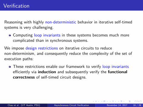
Reasoning with highly non-deterministic behavior in iterative self-timedsystems is very challenging.
Computing loop invariants in these systems becomes much morecomplicated than in synchronous systems.
We impose design restrictions on iterative circuits to reducenon-determinism, and consequently reduce the complexity of the set ofexecution paths:
These restrictions enable our framework to verify loop invariantsefficiently via induction and subsequently verify the functionalcorrectness of self-timed circuit designs.
Design restrictions: A module is ready to communicate with other modulesonly when it finishes all of its internal operations and becomes quiescent.
Chau et al. (UT Austin, PSU) Asynchronous Circuit Verification November 14, 2017 16 / 26
Verification
Reasoning with highly non-deterministic behavior in iterative self-timedsystems is very challenging.
Computing loop invariants in these systems becomes much morecomplicated than in synchronous systems.
We impose design restrictions on iterative circuits to reducenon-determinism, and consequently reduce the complexity of the set ofexecution paths:
These restrictions enable our framework to verify loop invariantsefficiently via induction and subsequently verify the functionalcorrectness of self-timed circuit designs.
Design restrictions: A module is ready to communicate with other modulesonly when it finishes all of its internal operations and becomes quiescent.
Chau et al. (UT Austin, PSU) Asynchronous Circuit Verification November 14, 2017 16 / 26

Outline
1 Introduction
2 The DE System
3 Modeling and Verification Approach
4 32-Bit Self-Timed Serial Adder Verification
5 Future Work and Conclusions
Chau et al. (UT Austin, PSU) Asynchronous Circuit Verification November 14, 2017 17 / 26
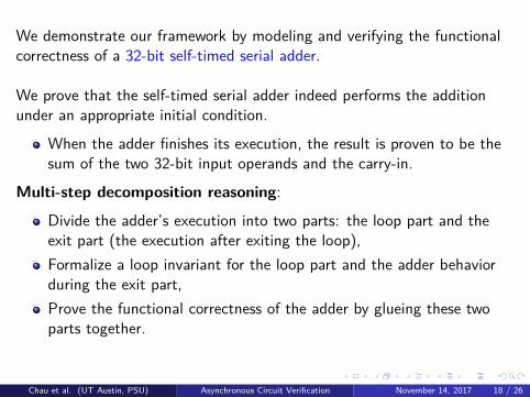
We demonstrate our framework by modeling and verifying the functionalcorrectness of a 32-bit self-timed serial adder.
We prove that the self-timed serial adder indeed performs the additionunder an appropriate initial condition.
When the adder finishes its execution, the result is proven to be thesum of the two 32-bit input operands and the carry-in.
Multi-step decomposition reasoning:
Divide the adder’s execution into two parts: the loop part and theexit part (the execution after exiting the loop),Formalize a loop invariant for the loop part and the adder behaviorduring the exit part,Prove the functional correctness of the adder by glueing these twoparts together.
Chau et al. (UT Austin, PSU) Asynchronous Circuit Verification November 14, 2017 18 / 26
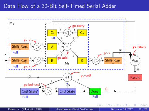
Data Flow of a 32-Bit Self-Timed Serial Adder
Shift-Reg00 1
�1�
Shift-Reg10 1
�1�
Ci
1�
A1�
B1�
+
Co1�
S1�
1�
1�
1�
1�
1�
Shift-Reg2
32�
App
33�
Result+15�
1�
1�
Cntl-State
5�
Cntl-State’5� Done- 015
�
go-a
go-b
go-buf-cntl
go-cntl
go-add
go-carry
go-s
go-result
M1
M2
Full
Full
Full
Full Full
Chau et al. (UT Austin, PSU) Asynchronous Circuit Verification November 14, 2017 19 / 26

Correctness Theorems
Theorem 1 (Partial correctness).
async serial adder(netlist) ∧ (1)init state(st) ∧ (2)(operand size = 32) ∧ (3)interleavings spec(input-list, operand size) ∧ (4)(st ′ = run(netlist, input-list, st, n)) ∧ (5)full(st ′.result.status) (6)
⇒ st ′.result.data = st.shift reg 0.data +st.shift reg 1.data +st.ci .data
Chau et al. (UT Austin, PSU) Asynchronous Circuit Verification November 14, 2017 20 / 26
Correctness Theorems
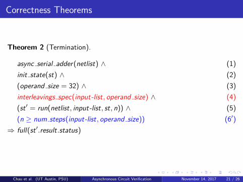
Theorem 2 (Termination).
async serial adder(netlist) ∧ (1)init state(st) ∧ (2)(operand size = 32) ∧ (3)interleavings spec(input-list, operand size) ∧ (4)(st ′ = run(netlist, input-list, st, n)) ∧ (5)(n ≥ num steps(input-list, operand size)) (6′)
⇒ full(st ′.result.status)
Chau et al. (UT Austin, PSU) Asynchronous Circuit Verification November 14, 2017 21 / 26

Outline
1 Introduction
2 The DE System
3 Modeling and Verification Approach
4 32-Bit Self-Timed Serial Adder Verification
5 Future Work and Conclusions
Chau et al. (UT Austin, PSU) Asynchronous Circuit Verification November 14, 2017 22 / 26

Future Work
We are developing new proof techniques for partial correctness ofself-timed circuit designs that DO NOT have any conditions on the valuesof go signals.
Our new method does not impose the aforementioned designrestrictions on loop-free circuits.
For termination proofs, we need a constraint on go signals guaranteeingthat delays are bounded.
We intend to follow a hierarchical approach to prove module-levelproperties of iterative circuits of the following form:
Given an initial state of the module, the module’s final state meetsits specification after that module completes execution.
Chau et al. (UT Austin, PSU) Asynchronous Circuit Verification November 14, 2017 23 / 26
ConclusionsWe have presented a framework for modeling and verifying self-timedcircuits using the DE system.
Our goal is to develop a methodology that is capable of verifying thefunctional correctness of self-timed circuit designs at large scale.
This work also provides a library for analyzing self-timed systems inACL2.
We model self-timed systems as networks of links communicating witheach other locally via joints, using the link-joint model introduced byRoncken et al.
We model the non-determinism of event-ordering in self-timed circuitsby associating each joint with an external go signal.
Our key proof techniques are hierarchical reasoning, multi-stepdecomposition reasoning, and induction.
Chau et al. (UT Austin, PSU) Asynchronous Circuit Verification November 14, 2017 24 / 26

References
W. Hunt (2000)The DE LanguageComputer-Aided Reasoning: ACL2 Case Studies, Kluwer Academic PublishersNorwell, MA, USA, 151 – 166.
M. Roncken, S. Gilla, H. Park, N. Jamadagni, C. Cowan, I. Sutherland (2015)Naturalized Communication and TestingASYNC 2015, 77 – 84.
A. Slobodova, J. Davis, S. Swords, and W. Hunt (2011)A Flexible Formal Verification Framework for Industrial Scale ValidationMEMOCODE 2011, 89 – 97.
Chau et al. (UT Austin, PSU) Asynchronous Circuit Verification November 14, 2017 25 / 26

Questions?
Chau et al. (UT Austin, PSU) Asynchronous Circuit Verification November 14, 2017 26 / 26