a & d drilling supply corporation presents drilling with…
TRANSCRIPT

1
A & D Drilling Supply Corporation PRESENTS Drilling with the PORTADRILLMINI ® Drill
Well Construction Methods And Tutorial! Revised Edition © 2004 A & D Drilling Supply Corporation/ PORTADRILLMINI® 2
lin e Experience in developing countries has shown that the construction of drilled wells must be simple and efficient. This keeps projects affordable, maintains a certain momentum and enhances local enthusiasm. This section describes how to set-up and drill with the PORTADRILLMINI® Drill - a compact, portable small rotary drill rig which has been successfully used in confined location well drilling in over 300 documented test site locations with great success.
Drilling With the PORTADRILLMINI® Drill Index
• Introduction
• Deciding to Drill With the PORTADRILLMINI®Drill
• Well Planning and Location
• Grounds Water Depth, Quantity and Quality
• Locating Where to Drill
• Pre-Drilling Preparations
• On-Site Set-up
• Preparing the Drill Site
• Mud Pit Design/Construction
• Re-Circulating Pits
• Using a Re-Circulating System
• Use of Drilling Additives & Fluids
2
• Drill Rig & Mud Pump Set-up
• PORTADRILLMINI® Drill Set-up
• The Drilling Process
• Water Injection Drilling Operation
• Adding Drill Steel (Water)
• Air injection of the PORTADRILLMINI ® Drill
• Adding Drill Steel (Air)
• Drilling Operation Using Domestic Water Supply
• Drilling Sand and Gravel
• Determining when a Water Bearing Formation has Been Penetrated
• Construction, Operation & Maintenance
• Source, Plant Site and Location
• Location of Public Drinking Water Wells
• Location of Potable Water Mains
• Prohibition on use of Lead Pipes, Solder & Flux
• Solution to Drilling and Well Problems
• Footnotes
IMPORTANT MESSAGE TO THE CONSUMER AND/OR OPERATION
This symbol of safety will be found throughout this manual alerting you to the possibility of injury. Don’t expose yourself or others to danger. Carefully read
each message that follows the safety symbol.
SAFETY RULES AND PRECAUTIONS As with any item of power equipment it is necessary that you learn and observe ALL safety precautions . This includes the care and use of the machine as well as personal safety . This machine is only as safe as the person who is operating it. DO NOT BE CARELESS! The PORTADRILLMINI® DRILL Must be leveled before drilling begins . Do not use on a slant or drill with machine tilted. Damage to the machine or operator may result. In the beginning you will be cautious. Don’t allow yourself to
3
become careless after you have become acquainted with the machine and its operation. DON’T EXPOSE YOURSELF OR OTHERS TO DANGER. Beware of overhead electric lines. DANGER : Keep hands, feet , hair and loose clothing away from moving parts . Do not operate the machine if you are sick or under medication. It is important that you remain alert during the drilling operation. IN ORDER TO AVOID INJURY, CONTACT LOCAL UTILITY COMPANY, POLICE OR CITY GOVERNMENT TO LOCATE ANY UNDERGROUND TANKS, PIPELINES OR ELECTRIC LINES. TRAINING Read the Operating and Service Instruction Manual carefully. Be thoroughly familiar with the controls and proper use of the equipment. Become familiar with the different drilling methods used for various rock formations. [ PREPARATION 1. Inspect the throttle control lever and cable. Make sure it is unobstructed and free from damage. Check the cable linkage running to the engine for kinks ,loose fittings, and obstructions that could impair the operation of the equipment. 2. Inspect the entire machine for loose parts, nuts, bolts, screws, etc. and tighten. 3. Before starting check all oil levels and grease all grease points . 4. DO NOT SMOKE WHILE FILLING THE FUEL TANK OR STARTING THE ENGINE . DRESS PROPERLY FOR THE JOB 1. It is advisable to wear a long sleeve shirt or jacket. Wear long trousers or slacks . 2. Do not operate this unit when barefoot or wearing sandals. Always wear substantial footwear,
leather work shoes or short boots function well for most people. 3. Do not wear loose clothing or jewelry that could become caught by moving parts . 4. Protective eye and ear protection suggested . Remember “ BETTER TO BE SAFE THAN SORRY. “ [ DOs & DON’Ts 1. NEVER start this machine or run the engine inside a closed room or building . Fumes from the exhaust contain dangerous carbon monoxide gas. 2. NEVER remove the fuel tank cap while the engine is running . 3. FINE TUNING YOUR ENGINE ….The engine should be tuned in its normal operating mode and with the bit attached.
BE SURE THE BIT IS NOT TOUCHING THE GROUND AND HAS NO OBSTRUCTIONS IT MIGHT STRIKE DURING THE TUNING PROCESS. All settings should be made slowly to allow the engine time to compensate for new settings. 4. NEVER TAMPER WITH ENGINE – GOVERNOR WHICH Is FACTORY SET FOR PROPER ENGINE SPEED. OVERSPEEDING ENGINE MAY INCREASE THE DANGER OF PERSONAL INJURY AND WILL VOID ENGINE WARRANTY. IF YOU THINK THE ENGINE GOVERNED HIGH SPEED NEEDS ADJUSTING, CONTACT YOUR NEARBY AUTHORIZED ENGINE
4
SERVICE DEALER , WHO HAS THE PROPER EQUIPMENT AND EXPERIENCE TO MAKE ANY NECESSARY ADJUSTAMENTS. 5. When repairing or inspecting , make certain all moving parts have stopped. Disconnect spark plug. 6. NOTE: NEW MUFFLERS WILL LOOSEN UP DUE TO “ BURN IN” …. Check this carefully during the first few hours of operating. 7. USE CAUTION AT ALL TIMES . Always survey the drilling area for dangerous obstacles , i.e., rocks, bottles, cans, wires, etc. Be sure the space surrounding area is clear of people , pets , etc. 8. NEVER HOLD THE DRILL IN A MANNER THAT MAY CAUSE YOU TO BE INJURED WHEN STRICKING AN UNDERGROUND OBSTRUCTION . 9. Watch out for traffic when working near roadways. Stay alert for uneven sidewalks, holes in terrain or other hidden hazards. 10. When removing the drill steel from the bore hole , never take out more than one section (five feet) at a time . Not only do you risk bending the drill steel , but it is easy to forget if you are near a powerline or other overhead obstructions . [ CARE AND MAINTENANCE Your PORTADRILLMINI ® Drill is designed and built to give you many years of dependable service. However , the continued good service depends largely on the care given to the unit. Note : This unit should be inspected before and after each use for: 1. Loose screws and bolts on the engine and transmission . 2. On / Off Switch wire , to be sure it has not been broken . 3. Proper fresh fuel is in the tank . (if unit has been stored with fuel in the tank for a period of time , drain old fuel and fill with new fuel.) 4. Be sure throttle is free and not binding . 5. Be sure to use original equipment when replacing sheer pins . ( these are designed to protect the engine and transmission.) PERIODICALLY CHECK TRANSMISSION LUBRICATION STORAGE Never store unit with gasoline in the tank in a building where fumes may reach an open flame or spark . Be sure engine has cooled before storing in any enclosure OR BEFORE PLACING A COVER OVER THE UNIT . [
The material presented here is based on the drilling experiences of the inventor of the PORTADRILLMINI ® Drill and from the extensive testing of the prototype. Basic drilling methods are also covered. While it does not cover every conceivable situation (drilling conditions can vary extremely), we have attempted to present an overview of drilling circumstances which will enable you to handle various situations as they might arise if you should encounter various rock formations. It is suggested to consult locally, of the methods used in well drilling in your area before drilling begins.
5
CAUTION:
[The PORTADRILLMINI ® Drill is designed to be used with accessories supplied
by A & D Drilling Supply Corporation / PORTADRILLMINI® only.[
Any modification, design change, or use of any unauthorized accessories with the PORTADRILLMINI ® Drill will be done at your own risk and may void
manufactures warranty.
CAUTION: The PORTADRILLMINI ® Drill unit leaves the manufacturing facility with NO ENGINE OIL OR GEAR BOX OIL ! This is done for shipping regulations . PLEASE , follow Engine manufacturers specifications for oil requirements . Transmission Oil Recommendations Operating Temperature Oil Type & Weight Above 32 º F SAE 30, 10W30,10W40, 15W40, Below 32 º F SAE 5W30
Introduction
The PORTADRILLMINI ® Drill U.S. Patent #6,315,059 is a small, portable, compact air/water / mud, rotary drilling machine manufactured in U.S.A. Using this small drill rig, it is
possible to rapidly complete safe, reliable water wells. Advantages of the PORTADRILLMINI ® Drill Include: confined location well drilling, one man operation, adaptable to utilize various drilling methods, simple operation, comparatively low cost, portability, and speed and depth to which the rig can go relative to manual methods (see Table 1).
Advantages of the PORTADRILLMINI ® Drill rigs are that it is capable of drilling diameters from 1 ½” inch borehole up to a 6" diameter. Mechanically rated at drill depth of up to 200 feet with maximum attainable drill depth is unknown? It can effectively penetrate hard rock Limestone, Sandstone, Coral rock, granite, loose boulders or coarse gravel. The PORTADRILLMINI ® Drill is capable of air/ water/ mud / foam injection methods. (see standard features )
6
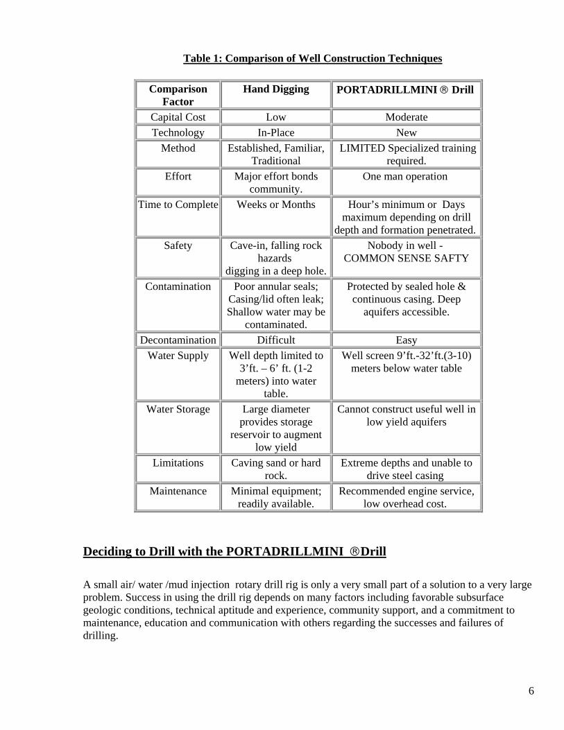
Table 1: Comparison of Well Construction Techniques
Comparison Factor
Hand Digging PORTADRILLMINI ® Drill
Capital Cost Low Moderate Technology In-Place New
Method Established, Familiar, Traditional
LIMITED Specialized training required.
Effort Major effort bonds community.
One man operation
Time to Complete Weeks or Months Hour’s minimum or Days maximum depending on drill
depth and formation penetrated. Safety Cave-in, falling rock
hazards digging in a deep hole.
Nobody in well - COMMON SENSE SAFTY
Contamination Poor annular seals; Casing/lid often leak; Shallow water may be
contaminated.
Protected by sealed hole & continuous casing. Deep
aquifers accessible.
Decontamination Difficult Easy Water Supply Well depth limited to
3’ft. – 6’ ft. (1-2 meters) into water
table.
Well screen 9’ft.-32’ft.(3-10) meters below water table
Water Storage Large diameter provides storage
reservoir to augment low yield
Cannot construct useful well in low yield aquifers
Limitations Caving sand or hard rock.
Extreme depths and unable to drive steel casing
Maintenance Minimal equipment; readily available.
Recommended engine service, low overhead cost.
Deciding to Drill with the PORTADRILLMINI ®Drill A small air/ water /mud injection rotary drill rig is only a very small part of a solution to a very large problem. Success in using the drill rig depends on many factors including favorable subsurface geologic conditions, technical aptitude and experience, community support, and a commitment to maintenance, education and communication with others regarding the successes and failures of drilling.

7
[
Before you try operating a PORTADRILLMINI ® Drill rig, it is important that you are familiar with:
• The equipments Design Limitations
• The Name and Function of each Major Part.
• What must be done to Maintain the Equipment.
• How to operate the equipment Safely.
In addition, when deciding to use the PORTADRILLMINI ® Drill the following factors should be seriously considered because they have a very strong bearing on the success or failure of a drilling project:
• Are there people in place who are already drilling using air, water, or mud rotary techniques? If not, are there people with a mechanical aptitude who are willing to learn how to drill and service the machinery?
• Are there local people who will be willing and able to maintain the well once it is installed?
• Are basic supplies (piping, fuel , plumbing supplies ) readily available?
• Is there sufficient technical support available to assist if problems are encountered?
• What equipment, if any (engine spares, water pumps ,well screens, hand pumps, etc) will need to be on hand to complete your drilling projects ? How reliable is the supply?
• Do the prospective users accept the process of drilling and taking water from an electric pump, or hand pump?
• Do the local people understand the associated costs (time, money and effort)?
• Are the people committed to actively participate in and complete the project?
WELL PLANNING AND LOCATION When drilling equipment is available, it is very tempting to get right to work and drill where drinking water is needed the most or where local leaders decide. Hastily drilling a well can result in personal injury or property damage . While these considerations are legitimate, they should be strongly considered ; water wells should be carefully planned located and constructed so that drilling only occurs where there is a high probability of successfully penetrating into water-bearing formations and where water wells can be effectively used, maintained, and protected from contamination. While every borehole will not result in a good drinking water well, advanced planning with the land owner and well driller will maximize the number of successful high yield wells and minimize drilling costs. In order to successfully plan the location of water wells, those involved must know something about the places where underground water occurs and how it got there.
8
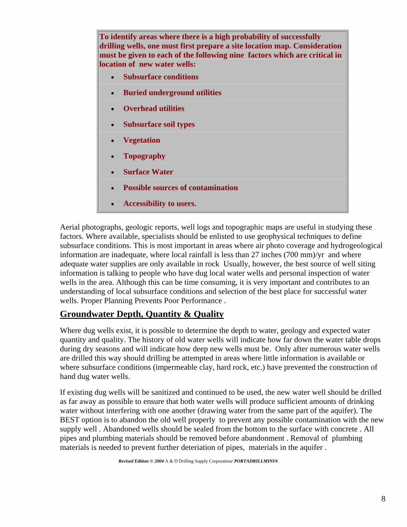
To identify areas where there is a high probability of successfully drilling wells, one must first prepare a site location map. Consideration must be given to each of the following nine factors which are critical in location of new water wells:
• Subsurface conditions
• Buried underground utilities
• Overhead utilities
• Subsurface soil types
• Vegetation
• Topography
• Surface Water
• Possible sources of contamination
• Accessibility to users.
Aerial photographs, geologic reports, well logs and topographic maps are useful in studying these factors. Where available, specialists should be enlisted to use geophysical techniques to define subsurface conditions. This is most important in areas where air photo coverage and hydrogeological information are inadequate, where local rainfall is less than 27 inches (700 mm)/yr and where adequate water supplies are only available in rock Usually, however, the best source of well siting information is talking to people who have dug local water wells and personal inspection of water wells in the area. Although this can be time consuming, it is very important and contributes to an understanding of local subsurface conditions and selection of the best place for successful water wells. Proper Planning Prevents Poor Performance .
Groundwater Depth, Quantity & Quality
Where dug wells exist, it is possible to determine the depth to water, geology and expected water quantity and quality. The history of old water wells will indicate how far down the water table drops during dry seasons and will indicate how deep new wells must be. Only after numerous water wells are drilled this way should drilling be attempted in areas where little information is available or where subsurface conditions (impermeable clay, hard rock, etc.) have prevented the construction of hand dug water wells.
If existing dug wells will be sanitized and continued to be used, the new water well should be drilled as far away as possible to ensure that both water wells will produce sufficient amounts of drinking water without interfering with one another (drawing water from the same part of the aquifer). The BEST option is to abandon the old well properly to prevent any possible contamination with the new supply well . Abandoned wells should be sealed from the bottom to the surface with concrete . All pipes and plumbing materials should be removed before abandonment . Removal of plumbing materials is needed to prevent further deteriation of pipes, materials in the aquifer . Revised Edition © 2004 A & D Drilling Supply Corporation/ PORTADRILLMINI®
9
Subsurface Soil Types
The quantity (or yield)(Gallons Per Minute) of an aquifer is as important as its quality. The only way to know exactly how much water is available in an aquifer (water bearing formation) is by test pumping existing or newly constructed water wells . However, a rough estimate of yield can be made by identifying the soil and rock which comprise the aquifer.
Most unconsolidated (uncemented) deposits of sand and gravel sized particles contain significant amounts of drinking water. However, the amount of water which can actually be pumped from these deposits depends on their density, thickness and permeability (how easy it is for water to flow through it). In general, the larger the grain size and the thicker the deposit, the higher the yield of the aquifer.
Fortunately, the PORTADRILLMINI ®Drill can effectively drill past boulders (loose rocks greater than 4” in. (10 cm) in diameter) or through loose gravel greater than 1-2 cm diameter. Special attention is to be taken in consideration to keep the borehole from collapsing and maintain circulation to carry the gravel up and out of the borehole. It is, therefore, important to inspect other water wells and steep slopes (valley sides, cliff faces, quarries, etc.) to determine if there are any boulders or coarse gravel present in the subsurface.
While sand and gravel deposits usually yield large quantities of water, try to avoid drilling and developing wells in shallow sand and gravel deposits if the water table is less than 10’ ft. (3 meters) below surface. Under these conditions, waste water can easily infiltrate back down to the water table near the well and contaminate the drinking water supply. This can be done if the well is cased with steel and sealed at the bottom into solid formation to prevent leakage .
Water wells constructed in silt or clay soils will have very low yields regardless of how they are constructed. To compensate for this, large diameter water wells should be carefully drilled so that large volumes of water can slowly accumulate in the well casing over time and provide sufficient quantities when required.
Finally, consolidated rocks, such as limestone, coral, sandstone or quartzitic rock, may also yield adequate quantities of water. Best yields are found where there are many pores, cracks, (fractures) and a thick zone of weathered rock. In general, fine grained rocks, such as shale, do not serve as productive aquifers.
Sometimes underground caves, caverns, and voids are encountered. This can be to your advantage if the void is below the water table. The void may be full of water, or the void could be full of sand or gravel. If the void is full of sand , ideally if possible -pump out the sand to create the void so that it may be filled with water.
Vegetation
During the dry season, survey for indications of groundwater by looking at the alignment of ant mounds and green vegetation in the midst of an arid landscape. Annual plants, such as grasses and ferns, are not good indicators because they come and go with the seasons. However, year-round reeds and broad leaf trees and shrubs like cedar and willow tend to grow where water is close to the surface.
10
Topography
The water table commonly follows the land surface, while the lowest areas (valley bottoms or depressions where water accumulates after rains) are generally the best place to drill, care must be taken to ensure that the site has good access, is not subject to flooding and is not close to where contaminated surface water may puddle or pond. The presence of water bearing fracture zones may be detected by surface features such as shallow linear depressions and abrupt changes in valley alignment. Often these features are difficult to see in the field but become apparent when viewed from the air.
SURFACE WATER Good water wells can often be drilled near streams, lakes, rivers, ponds, and canals if the water well is deep, groundwater may be available even if a river is temporarily dry. This is known as “Saturated areas” . Reliable water wells have even been located in or close to broad sandy riverbeds, which are active once every 5-10 years. Water taken from wells located at least 50’ft. (15 m) from a river is usually cleaner and cooler than water taken from the river. If the well water remains turbid after construction and test pumping well, the soils may be providing inadequate filtration and contaminated river water may be drawn into the well.
WARNING --Drilling wells in zone saturation areas that are prone to broad fluctuation of the water table could eventually cave -in the well. This could also be possible in consolidated formations as larger rocks, or boulders could fall from the well walls and lodge in the well. Special consideration should be given to the presence of springs and seeps (wet or marshy areas). Underground water movement can in time cave in unconsolidated well formations. Springs on the side of a hill may indicate the presence of a water bearing formation (aquifer). A successful water well can often be constructed into this aquifer by drilling just uphill of the spring. Animal trails often lead to seeps and springs.
Finally, surface drainage patterns can be used to determine rock type
• Trellis and rectangular drainage develops where dipping, fractured sedimentary rocks are present; these are the most favorable areas for high yield aquifers
• Contorted drainage develops over folded rocks. Water bearing tension fractures and gaps between layers of differing hardness sometimes develop near the top of folds;
• Annular drainage typically develops over volcanic or intrusive (granitic) domes, with streams flowing along water bearing fracture zones;
• Dendritic or branching patterns with a large number of tributaries are typical of drainage in areas of impermeable crystalline rock such as gneiss. Parallel drainage patterns may develop in areas with linear water bearing structures such as faults and dikes.
Revised Edition © 2004 A & D Drilling Supply Corporation/ PORTADRILLMINI®
11
Sources of Contamination
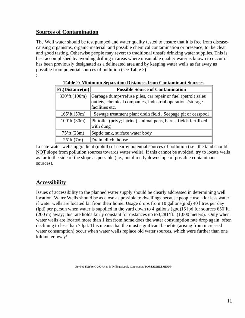
The Well water should be test pumped and water quality tested to ensure that it is free from disease-causing organisms, organic material and possible chemical contamination or presence, to be clear and good tasting. Otherwise people may revert to traditional unsafe drinking water supplies. This is best accomplished by avoiding drilling in areas where unsuitable quality water is known to occur or has been previously designated as a delineated area and by keeping water wells as far away as possible from potential sources of pollution (see Table 2) :
Table 2: Minimum Separation Distances from Contaminant Sources Ft.)Distance(m) Possible Source of Contamination
330’ft.(100m) Garbage dumps/refuse piles, car repair or fuel (petrol) sales outlets, chemical companies, industrial operations/storage facilities etc.
165’ft.(50m) Sewage treatment plant drain field , Seepage pit or cesspool 100’ft.(30m) Pit toilet (privy; latrine), animal pens, barns, fields fertilized
with dung 75’ft.(23m) Septic tank, surface water body 25’ft.(7m) Drain, ditch, house
Locate water wells upgradient (uphill) of nearby potential sources of pollution (i.e., the land should NOT slope from pollution sources towards water wells). If this cannot be avoided, try to locate wells as far to the side of the slope as possible (i.e., not directly downslope of possible contaminant sources).
Accessibility
Issues of accessibility to the planned water supply should be clearly addressed in determining well location. Water Wells should be as close as possible to dwellings because people use a lot less water if water wells are located far from their home. Usage drops from 10 gallons(gpd) 40 litres per day (lpd) per person when water is supplied in the yard down to 4 gallons (gpd)15 lpd for sources 656’ft. (200 m) away; this rate holds fairly constant for distances up to3,281’ft. (1,000 meters). Only when water wells are located more than 1 km from home does the water consumption rate drop again, often declining to less than 7 lpd. This means that the most significant benefits (arising from increased water consumption) occur when water wells replace old water sources, which were further than one kilometer away!
Revised Edition © 2004 A & D Drilling Supply Corporation/ PORTADRILLMINI®

12
Another factor in preparing Water Wells Development Projects is to determine how many water wells are necessary to serve the population. When more than 300 people use one handpump equipped well, there will be significant waiting lines to get water. Another option could be to drill a large enough well for supply and then construct multiple hand pumps plumbed from the same well supply pipe. This requires the use of multiple check valves also.
Ensure that the site is accessible year-round and that the access route to the water well is not susceptible to flooding. Finally, ensure that the site has legal access, which is acceptable to users from a societal standpoint. Disputes involving private ownership of land should be avoided. Land ownership law is usually different than what we are used to and requires careful consideration. Having water well on someone's property enhances its value and therefore a formal arrangement for access needs to be clearly made before the well is drilled.
Preparation of a Site Map
A map of the village and surrounding area should be prepared. Add to the map all relevant features such as dwellings, animal pens, pit toilets, rivers, swampy areas, garbage disposal areas, underground utility locations and indicate the direction in which the land slopes. Draw all alternative well sites on the map and select the best site.
There is rarely an ideal location and the relative advantages and disadvantages of each site must be weighed. The people that will be using the well and the drillers must together decide which site is best for the project. Since selecting the best site is a matter of judgement and experience, it always helps to seek assistance from hydrogeologists - while their investigation may be time consuming and add some cost to the drilling project, it will help ensure that a site is selected which will provide a safe, abundant supply of drinking water.
Sources of Groundwater Information
Information, which can help effectively site water wells, includes aerial photographs, geologic reports, well logs, topographic maps, geophysical maps etc. Sources of this information are listed below. It should be emphasized again, however, that the best source of well siting information is talking to people who have dug local water wells and personal inspection of wells. Keep in mind that:
1. Information is often available in-country from government agencies (such as Ministries of Development, Rural Affairs, Geological Survey etc);
2. In-country information is also often available from libraries and international development/aid agencies;
3. Often excellent information can be obtained by talking to consultants, hydrogeologists and well drillers who have worked in the area of interest;
4. Libraries in most large urban centers in the United States and Canada often contain good information (make use of inter-library loan facilities!). To determine which library is the closest depository for United Nations material, call the UN office at (212) 963-7444;
5. The United Nations Reference Library (Map Section) in New York is also a good source of information (212-963-0536). Delivery only available through regular mail.
13
6. The Library of Congress (Mapping Section) in Washington DC has many hydrogeological reports and maps for developing countries (202-707-6277). Requests must be made in person or in writing. Unless a visit is made in person, response time to search requests is very slow (2-3 weeks); additional time is required for delivery.
7. Hydrogeological reports for many countries of the world are available from the National Groundwater Association (NGWA) Information Center at 3675 Riverside Dr, Dublin OH, 43107 (800-332-2104). There is an on-line search facility available for a fee; credit card payment and overnight delivery service are available. There is a minimum $12 base fee for retrieving up to 20 pages (extra fee/page for additional pages).
The success in the location of productive water wells has improved from 50-60 percent (based on site reconnaissance and air photo interpretation) to over 90 percent when geophysical technology is used. Geophysical surveys employ instruments that quickly and cheaply measure the physical properties of soil and rock (density, magnetism, electrical conductivity, radioactivity etc.). Geophysical surveys can be very useful in locating water-bearing fault zones, in finding an adequate thickness of overburden or weathered bedrock, and in assessing the depth to the water table. Success depends on the application of appropriate techniques, having enough time to do the investigation, and having the equipment operated and the results interpreted by trained geologists. In some countries, the government provides geophysical surveys as a service. For design purposes, 1.5 gpd (5 lpd) is the minimum consumption level and 7 gpd (25 lpd) is an acceptable goal in places where piped connections to individual houses are not feasible. It should be noted that the quantity (Gallons Per Minute) requirement of water needed might also be significantly affected by the number of livestock that require water and by whether the water is to be used for garden irrigation.
Even with close, clean water, education is crucial. Unless people understand the benefits clean water can bring, they will not make effective use of a newly drilled well and it may have little benefit! Education is also important for on-going well maintenance; if people see clean water as being vital to them, they will be willing to occasionally spend a little time and money to keep their water supply safe and functioning reliably.
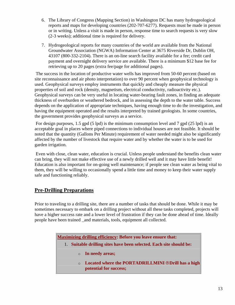
Pre-Drilling Preparations Prior to traveling to a drilling site, there are a number of tasks that should be done. While it may be sometimes necessary to embark on a drilling project without all these tasks completed, projects will have a higher success rate and a lower level of frustration if they can be done ahead of time. Ideally people have been trained _and materials, tools, equipment all collected.
Maximizing drilling efficiency: Before you leave ensure that: 1. Suitable drilling sites have been selected. Each site should be:
o In needy areas;
o Located where the PORTADRILLMINI ®Drill has a high potential for success;
14
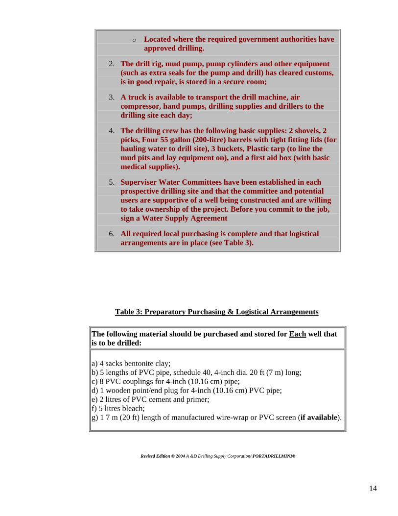
o Located where the required government authorities have approved drilling.
2. The drill rig, mud pump, pump cylinders and other equipment (such as extra seals for the pump and drill) has cleared customs, is in good repair, is stored in a secure room;
3. A truck is available to transport the drill machine, air compressor, hand pumps, drilling supplies and drillers to the drilling site each day;
4. The drilling crew has the following basic supplies: 2 shovels, 2 picks, Four 55 gallon (200-litre) barrels with tight fitting lids (for hauling water to drill site), 3 buckets, Plastic tarp (to line the mud pits and lay equipment on), and a first aid box (with basic medical supplies).
5. Superviser Water Committees have been established in each prospective drilling site and that the committee and potential users are supportive of a well being constructed and are willing to take ownership of the project. Before you commit to the job, sign a Water Supply Agreement
6. All required local purchasing is complete and that logistical arrangements are in place (see Table 3).
Table 3: Preparatory Purchasing & Logistical Arrangements
The following material should be purchased and stored for Each well that is to be drilled:
a) 4 sacks bentonite clay; b) 5 lengths of PVC pipe, schedule 40, 4-inch dia. 20 ft (7 m) long; c) 8 PVC couplings for 4-inch (10.16 cm) pipe; d) 1 wooden point/end plug for 4-inch (10.16 cm) PVC pipe; e) 2 litres of PVC cement and primer; f) 5 litres bleach; g) 1 7 m (20 ft) length of manufactured wire-wrap or PVC screen (if available).
Revised Edition © 2004 A &D Drilling Supply Corporation/ PORTADRILLMINI®
15
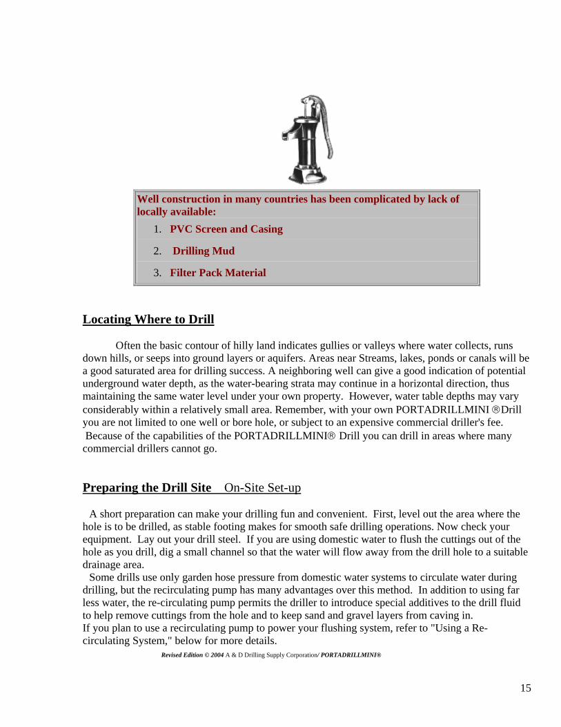
Well construction in many countries has been complicated by lack of locally available:
1. PVC Screen and Casing
2. Drilling Mud
3. Filter Pack Material
Locating Where to Drill Often the basic contour of hilly land indicates gullies or valleys where water collects, runs down hills, or seeps into ground layers or aquifers. Areas near Streams, lakes, ponds or canals will be a good saturated area for drilling success. A neighboring well can give a good indication of potential underground water depth, as the water-bearing strata may continue in a horizontal direction, thus maintaining the same water level under your own property. However, water table depths may vary considerably within a relatively small area. Remember, with your own PORTADRILLMINI ®Drill you are not limited to one well or bore hole, or subject to an expensive commercial driller's fee. Because of the capabilities of the PORTADRILLMINI® Drill you can drill in areas where many commercial drillers cannot go. Preparing the Drill Site On-Site Set-up A short preparation can make your drilling fun and convenient. First, level out the area where the hole is to be drilled, as stable footing makes for smooth safe drilling operations. Now check your equipment. Lay out your drill steel. If you are using domestic water to flush the cuttings out of the hole as you drill, dig a small channel so that the water will flow away from the drill hole to a suitable drainage area. Some drills use only garden hose pressure from domestic water systems to circulate water during drilling, but the recirculating pump has many advantages over this method. In addition to using far less water, the re-circulating pump permits the driller to introduce special additives to the drill fluid to help remove cuttings from the hole and to keep sand and gravel layers from caving in. If you plan to use a recirculating pump to power your flushing system, refer to "Using a Re-circulating System," below for more details. Revised Edition © 2004 A & D Drilling Supply Corporation/ PORTADRILLMINI®
16
Now check your equipment. Lay out your drill steel and drill bits. Place the drill stems on a box, or something similar, and grease both ends of the steel. Drill thread grease is very important to aid in removal of drill steel preventing galling of threads. Now they are ready for use. Also, have three pipe wrenches on hand. The pipe wrenches will be used to add and remove drill steel. Drill steel vise grips will be needed to grasp drill steel during removal operation as to prevent loss of drill steel in the hole. Unload all the tools and equipment near the pre-selected drilling location. If possible, orient the drill rig so that it will be shaded during the afternoon. Select a dry, preferably granular location to lay the drill pipes so that the threads do not get dirt, dust or insects inside of them. Since it is very hard to clean sand from greased threads, keep the pipes off the ground by placing them on two boards (or tree branches). Clean dirt from threads using a hand held wire brush.
Fill the four 200 liters (55 gallon) barrels with water (or hire someone to do it) and supply water as required throughout the drilling process. Arrange the water barrels next to the area where the pits are to be dug. Add 1 cup of chlorine to each barrel of water to ensure that bacteria are not injected into the groundwater during drilling (unless you are using polymer to thicken your drilling fluid.)
Fence off an area behind which all observers must stand during the drilling process. Designate one of the drillers or local leaders to ensure that this safety rule is observed at all times and to frequently explain what is happening and why this work is being done.
Identify the exact location of the proposed well and hand dig a 4 inch diameter "well guide hole" about 6 inches deep. Since erosion can be a big problem and cuttings must be kept clear of the borehole, it may be necessary to install a 3’ft. (1 m) long 5 or 6 inch diameter "surface casing" with a "tee" or discharge pipe going to the settling pit.
Revised Edition © 2004 A & D Drilling Supply Corporation/ PORTADRILLMINI®
17
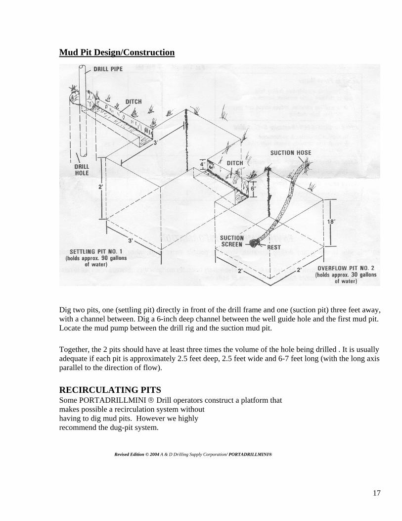
Mud Pit Design/Construction
Dig two pits, one (settling pit) directly in front of the drill frame and one (suction pit) three feet away, with a channel between. Dig a 6-inch deep channel between the well guide hole and the first mud pit. Locate the mud pump between the drill rig and the suction mud pit.
Together, the 2 pits should have at least three times the volume of the hole being drilled . It is usually adequate if each pit is approximately 2.5 feet deep, 2.5 feet wide and 6-7 feet long (with the long axis parallel to the direction of flow). RECIRCULATING PITS Some PORTADRILLMINI ® Drill operators construct a platform that makes possible a recirculation system without having to dig mud pits. However we highly recommend the dug-pit system. Revised Edition © 2004 A & D Drilling Supply Corporation/ PORTADRILLMINI®
18
RECIRCULATING PITS SYSTEM The pit dimensions are recommended to allow maximum settling of the cuttings before the flush water is recirculated (holds approx. 100 gallons of water). Using pits of this size together with drilling fluid additives such as Super Mud polymer and bentonite clay will prevent most formation problems such as cave-ins. The suction screen must be supported off the bottom of the overflow pit to prevent pumping of solids. Clean the pits periodically to remove the cuttings. This protects your pump from excessive cuttings.
The circulating (drilling) fluid performs many functions in rotary mud drilling applications: 1. To clean the drill bit and remove the cuttings from the hole by transporting the cuttings to the surface and release them dropping the cuttings in the settling pit(s). 2. To provide borehole stability by preventing caving and washouts. 3. To prevent excessive loss of drilling fluid to permeable zones. To stop fluid loss into porous formations.
4. Cool the drill bit and lubricate the drill string. 5. To ensure the required information about the formation penetrated, and their contents, is obtainable 6. To provide protection to formation productivity. 7. To control subsurface pressures.
There are many fine commercially available additives from which to choose. Most of them fall into two categories: one group is based on bentonite clay and the other on organic polymers. Here's the difference and what they are for:
The clay-based products form a thin "filter-cake" along the walls of the drill hole. This "cake" is about 1/32" thick and once formed, prevents the escape of drilling fluid water into the formations through pores or voids in the rock.
This means that all of the fluid pumped down into the hole will come back out. These clay-based products can also be used in highly concentrated form to "plug" off fractures in the borehole wall and prevent escape of drilling fluids. Finally, they reinforce unconsolidated walls and help retard caving-in situations.
The organic polymer based products are newer than the clays. Their main function is to add viscosity (thickness) to the fluid without adding weight. The thicker fluid can easily lift much heavier particles (sand and gravel) than "regular" water. In addition, the organic polymers increase the "gel strength" of the fluid. This means that suspended particles in the hole will tend to stay suspended when the pump is shut off for drill steel change. Otherwise, these particles would collapse onto the bit and pin it to the bottom. This can ultimately plug the drill bit preventing circulation. Often when this happens it is mistaken for a cave-in. Proper use of drilling fluid additives can work to your advantage, thereby working for you instead of against you. Drilling fluids should be used as a tool to avoid borehole troubles and other drilling problems, thereby reducing the total cost of drilling and completing a well. Revised Edition © 2004 A & D Drilling Supply Corporation/ PORTADRILLMINI®
19
Using a Re-Circulating System
This is a simple and effective way to use the same fluid (normally just water and additives) to drill the hole and carry the cuttings to the surface, where it flows into 2 holding basins called mud pits. This system is used universally in large water well and petroleum-well drilling. It works in this manner: a pump is used to draw water from the #2 mud-pit, through the pump, and down the drill stems to the bit. The water cools the bit, and flushes the cuttings up and out of the hole. The cuttings will settle in the #1 pit, and can be removed with a shovel. (See Figure 2). A small canal you excavate between the #1 pit and the #2 pit allows the water to flow from #1 into #2. It is important to use a pump capable of pumping an abrasive fluid mixture. The mud-pits you dig should hold between 50-100 gallons of water each and must be at least eighteen inches deep so that the pump's suction screen will always be covered by water. This suction screen (located at the end of the suction hose) should be at the end of the mud-pit #2, to prevent excessive cuttings from being re-circulated with the water. The mud-pit itself should be conveniently located about two to four feet from the drill hole. When using the pump, be sure to use the proper fuel and place the pump on a board or solid, level ground. Make sure that the suction-hose connections are tight, since failure to get and hold suction is generally due to air leakage at the fittings. Connect the pressure hose from the pump to the swivel inlet. You may decide to use a full-flow valve (a 1" gate valve would be suitable) in the discharge side of the pump, anywhere between the pump and the swivel. Simply shut off the gate valve and shut off the centrifugal pump. The gate valve will insure against loss of prime. When first starting your pump, you need to prime the pump. To do this, fill the pump housing and suction hose with water. Start the pump at once and run it at full throttle to get the water circulating. The outlet of the pump must be open to let the water flow after priming. Once the pump is filled and discharging water it should hold its prime. This is particularly true it you have a tight suction hose fitting, and if a good gate valve is used in the discharge line. Remember, if you shut off the pump and open the discharge hose, the water can run out of the pump and suction hose and lose the prime. One of the best advantages of the re-circulating system is that drilling additives can be mixed with the re-circulating water. Also drilling into a water-bearing formation with artesian pressure will be indicated by an overflowing mud-pit. The recirculating system also helps save water.
CAUTION: When you have drilled down five feet, allow the pump to flush the hole out for a few minutes. The deeper you go, the longer amount of time you should allow the flushing action to remove all cuttings from the drill hole. This will help prevent cave-ins and trapped bits.
Also, it is important not to leave the drill steel in the bore hole for more than a few minutes with the water turned off. If there is clay or muck in the drill hole and if the water is left off too long, the drill steel may be hard to remove. When the drilling is stopped for the day, remove the drill steel from the hole to prevent muck or mud from locking the Drill Steel in the bore hole. Revised Edition © 2004 A & D Drilling Supply Corporation/ PORTADRILLMINI®
20
If the soil in the pit is quite permeable (sandy), consider lining the pits with un-punctured plastic (especially if water is scarce). Carefully wrap the edge of the plastic over and bury it a foot or more into the ground along the flow channels to prevent drilling fluids from flowing beneath the plastic. Alternatively, pits can be constructed from wood (with or without plastic liners) or four 55 gallon drums which have been sawn in half could be dug-in and used as pits (rectangular pits are best)!
Use of Drilling Additives and Fluids
The reason for using drilling additives such as SuperMud or SupraFoam in the re-circulating water is to improve performance in hole cutting, cleaning, stability, and productivity. Properly formulated and maintained drilling fluids enable the driller to carry out his operations with increased efficiency and improved results. The drilling fluid should be thought of by the driller as a useful tool at his disposal.
WARNING
Before starting the engines on either the rotary drill or the mud pump, you MUST ensure that the crankcases on both the engines are filled with SAE 30 oil up to the filler hole. Check gear box, gear oil level. CAUTION: change the oil after the first 5 hours operation for new machines Learn more about maintenance!
PREVENTATIVE MAINTANENCE
The parts of the PORTADRILLMINI ® Drill that uses grease is the swivel, wheel axles, and pulldown cable idler pulleys. Apply grease liberally to the Grease fittings on the Swivel until you see grease at the surfaces of the seals. Using a grease gun, pump grease into both wheel axles at the grease fittings. With lightweight spray oil lubricate all wire rope cables. Replace cables at FIRST signs of wear. Maintenance and care for Tri-Cone or Roller cone type drill bits should include washing the drill bit after use and storing in oil or spray the bearings with oil so as to not rust the bearings from use in water. The drill bit should be submerged in any kind of oil at least to the level over the bearings. Rusted bearing cause pitting of the bearings which causes wear and rusted bearings can also lock up and not rotate.
Revised Edition © 2004 A & D Drilling Supply Corporation/ PORTADRILLMINI®
21
Drill Rig & Mud Pump Set-up -Set-up the PORTADRILLMINI ®Drill , air compressor or mud pump following the steps outlined below
• Erect the drilling machine over the guide hole; level the ground around it. MACHINE must be leveled for straight well bores. Also drilling on crooked surfaces puts a bind on drill steel and strain on equipment. (Use a small magnetic carpenter’s level held against the Mast on two adjacent surfaces).
Connect hoses as follows • One hose to the middle port of the 3 way Valve, and the other end to the Mud Pump discharge
port (top side);
• One end of Suction Hose Assembly to suction port of mud pump and lower the strainer into a 5-gallon pail placed submersed in the suction pit. The pail is required to avoid re-circulating cuttings back down the hole;
• The 20' hose (with both ends fitted) from the top port of the mud pump to the side port of the swivel on the PORTADRILLMINI ® Drill injection assembly;
• It is suggested to have a by-pass hose that can be fitted to a tee in the discharge side of the mud pump to divert circulation to the mud pit while changing drill steel as to not have to shut off the mud pump every time to change drill steel.. Allow end to hang in the settling pit or in the return ditch between borehole and settling pit.
To prevent the PORTADRILLMINI ® Drill engine from stalling when the throttle is turned all the way to the closed (idle) position; adjust the choke as follows prior to initial starting:
• Remove air filter from carburetor;
• Pull throttle control cable all the way out;
• Keeping the throttle in the full open position, move the cable in the direction that will completely close the choke valve in the carburetor. Re-tighten the cable clamp.
• Raise the drill head (engine/clutch assembly) to a convenient level to pull the starting rope (it is always easiest to start the engine prior to raising the drill head to the top). To start the PORTADRILLMINI®Drill engine activate the choke mechanism by pulling the throttle cable all the way out. Pull the starting rope vigorously (several times may be necessary). When engine starts, immediately push the throttle cable back in until the engine runs smoothly.
Revised Edition © 2004 A & D Drilling Supply Corporation/ PORTADRILLMINI®
22
PORTADRILLMINI ® Drill Set-up
To ensure that the PORTADRILLMINI ® Drill output (drive) shaft does not rotate when the throttle is in the idle position, check and adjust it as follows:
• With the engine running, turn the throttle control against the stop to the idle position (opposite direction to the choke position);
• If the output shaft is turning, adjust the idle set screw on the carburetor throttle governor linkage to reduce the RPM to a point where the output shaft stops turning;
• If adjusting the screw is ineffective, adjust the length of the spring on the governor linkage by either stretching it or bending the ends to shorten it.
Secure a 4 inch drill bit on the end of the drill steel pipe with a pipe wrench after cleaning and lubricating the threads of both the drill steel pipe and drill bit.
The Drilling Process
[ ▽When the desired drilling locations are determined and reached, check for possibilities of underground utilities before proceeding.[ Remember –Safety First [ Starting the engine in the lowered position check all fluid levels. [ Make sure the machine is leveled. [Drilling on a surface that leaves the machine crooked will produce a crooked well and puts a bind on the drill string ultimately causing mechanical failure.[ A borehole is drilled by rotating a bit at the end of drill pipe. Borehole cuttings are removed by continuous circulation of air injection or drilling fluid as the bit penetrates the formation. The drill pipe is connected to the drill engine. Compressed air injection, water injection or drilling fluid is pumped down through the hollow drill pipe using an air compressor or centrifugal pump (mud pump) to a drill bit. The circulation or fluid flows upward in the annular space between the drill pipe and the borehole to the surface where it is channeled into a settling pit and most of the cuttings drop out. Fluid from the settling pit overflows into a second pit (suction pit). Relatively clean fluid from the second pit is then pumped back through the drill pipe and the cycle repeats.
Revised Edition © 2004 A & D Drilling Supply Corporation/ PORTADRILLMINI®
23
Mud Injection Drilling Operations
Let us assume that the ground you will begin drilling in is material other than solid rock. First, start
the PORTADRILLMINI® Drill engine and warm it up for at least one minute; this helps prolong the life of your valuable unit. Use drill steel thread grease on all threads. Connect a drill steel and the drill bit to the end of the swivel; then connect the pressure hose to the water injection flow control valve. Place the drill bit at the point where you wish to start drilling. Turn on the water, and speed up the engine. Lower the unit with the winch. You are now drilling!
As you drill into the ground you can determine the type of rock formation material you are drilling in by looking at the cuttings coming out of the hole with the water. It is important to be aware of the different kinds of material encountered, as they will indicate potential water-bearing formations, as well as the type of strata you must pass through to reach the water-bearing formation. Keep a record or log of the types of formation material you encounter at various depths. When you use additives, the flush water has the consistency of buttermilk. Using water from the 200 liters (55 gallon) drums, fill the mud pits to the very top. Make sure that the pits are full of water during the entire drilling process. This must be done to ensure that the cuttings will settle-out.
Fill the fuel tank of the drill engine and start it. With engine running in idle, raise the drill head to a sufficient height to allow the installation of a drill pipe section with the drill bit. Turn pipe by hand to thread it onto the swivel thread until it is all the way on.
Lower the drill bit into the prepared hand dug guide hole. Allow the drill pipe to rotate above the bottom of the guide hole.
Fill the fuel tank of the mud pump and start it using the following process:
• Prime the pump before starting the engine by removing the discharge hose or the plug on top of the pump housing and pouring water into this opening until full. It will take a good amount of water since the Suction Hose will also be filled up.
• Set the choke and run levers to the CHOKE and RUN positions respectively. These controls are located on the side of the fuel tank opposite the pump side of the engine.
• Pull the starting rope (several times may be necessary), and when engine starts to run, immediately return the choke lever to the OFF position. Leave the run lever in the RUN position. Note that it will take a few minutes for the pump to prime.
Increase the engine RPM until the clutch engages and the pipe starts turning. Turn the 3 way Valve so that the water will circulate from the Mud Pump through the bottom by-pass hose back to the pit. Add water as required to top-up the pits. Then turn the valve so that water flows into the drill swivel. Make sure no water is leaking from the swivel seals. If it is, re-direct the water through the by-pass hole or stop the mud pump. Pump grease into the top & bottom grease fittings before drilling. It may be necessary to repeat this process during the drilling operation. Revised Edition © 2004 A & D Drilling Supply Corporation/ PORTADRILLMINI®
24
When the water begins pumping through the drill pipe, it will make a lot of splashing so make sure the drill operator is ready to lower the drill pipe into the hole fairly rapidly. After the drill has penetrated a foot or so, there will be a smooth flow of water. Maintain a slight backpressure on the winch handle; at an easy drilling speed, the winch handle should make a full circle every 20 seconds or so. Do not exceed this speed or the water will not be able to circulate the cuttings out of the hole fast enough (causing the bit to seize) and/or the borehole walls will not be coated with enough fines to resist caving! In harder formations it should make a full circle every 40 seconds. In very hard rock, a drilling rate of 1 to 5 feet per hour is to be expected. Soft to medium formations, 5 ft. per every 15 minutes. Adding Drill Steel
When you have reached the end of the first five foot drill steel, pull the steel up enough to grip a pipe wrench on the drill steel coupling and clamp the vise grips below the drill steel coupling so that the drill steel guide table provides the support. Turn off injection. Air Injection Operation of the PORTADRILLMINI ® Drill
[▽ When the desired drilling location is determined and reached, check for possibilities of underground utilities before proceeding.[ Remember “Safety First”. Starting with the engine in the lowered position check all fluid levels. [ Make sure the machine is leveled.[ Drilling on a surface that leaves the machine crooked will produce a crooked well and puts a bind on the drill string ultimately causing mechanical failure. [ Install weights on each side of weight bar. Use weights on weight bar pull down assist according to rock formation drilling. Ideal drill speed will be constant cutting with out bouncing of drill steel. To quickly, of a cut will result in the drill bit getting ahead of the cutting circulating out of the hole or the well will not be evacuated fast enough and therefore lose circulation ultimately to trap the drill bit and lock up in the hole. Connect air supply hose to airflow control valve. (OPTION) Connect water supply hose to water flow control valve. Hoist engine to topmast position. Grease connections with drill thread grease and install drill bit on drill steel. Install drill bit down through drill steel opening at main base water deflector shield. Thread drill steel coupling to drill steel and to steel swivel located below the gear reduction transmission drive box. The drilling assembly is now ready for drilling to begin. Switch the engine stop switch to the on position, and start engine. Open throttle and open injection flow control valves accordingly. Grasp winch handle crank. Engage cable pull down system winch to the neutral position and lower drill bit to the ground. Drill bit then cuts or loosens the earth. Pay attention to injection circulation, cuttings should be coming out of the borehole. As you reach the end of the first drill steel drilling down to maximum depth of the first drill steel, pull up till coupling passes through the drill steel table guide enough to grasp with a pipe wrench to break out of the threaded coupling for addition of next drill steel. This is a good time to check the fuel level before raising the engine to topmast position. The engine is hoisted to allow clearance for the next section of drill steel to be threaded to the steel swivel. Grease threads of next drill steel and coupling. Install next drill steel. Example- install drill steel to first drill steel coupling then lower engine. Leave steel swivel threads just over the coupling. Now thread coupling to swivel threads. Restart engine. Open-air injection flow control valve slowly. Once circulation is regained disengage winch to lower drill bit. Drill time cutting will become faster with each piece of drill steel added, as weight is increase from added steel. Revised Edition © 2004 A & D Drilling Supply Corporation/ PORTADRILLMINI®
25
Injection Air or Drilling Fluid Backflow Sometimes injection air and/or drilling fluid comes up through the Drill Steel when you disconnect the swivel. This is caused by falling borehole cuttings pressurizing drilling fluids at the bottom of the hole. It can also be an indication of trapped air in underground voids. Immediate action is required because this occurs when either the borehole is caving-in or when drill cuttings have not been cleaned well enough from the borehole. If you notice backflow of air and/or drilling fluid, immediately re-connect the Drill Steel and continue circulation to clean-out the cuttings. If caving is suspected, thicken the drill mud using PORTADRILLMINI® SuperMud while continuing circulation. WARNING It is not recommended to leave the drill unit unattended. Operator controls by grasping winch handle to control drilling cut. Letting the drill free fall if a void or pocket is reached may cause injury if handle hits the operator or drill can drop unexepectantly and slam into the bottom of a void causing mechanical failure. By maintaining control of the speed of the fall of the drill bit you can feel the speed of the cut. By winding the winch in reverse activates pull down pressure system. Wind even downward pressure leaving constant pressure on drill bit. WARNING Excessive down pressure will cause unit to be lifted off the ground. This will cause mechanical failure. Too much down pressure lifting the unit off the ground can cause torque spin of the unit. Losing center position inside well. In hard rock, insufficient pressure on the drill steel pipes may result in an extremely low drilling speed. Caution should be used to avoid excessive pull-down pressure (weight) exerted on the drill string because this may result in crooked holes, bent drill rods and jammed drill bits. Rotation speed should be slowed as the pull-down pressure increases. Watch that the air / or water/ or mud is circulating continuously when the drill is rotating.
As soon as the drill has penetrated 2 feet or so, take sample cuttings from the first small pit and place them on the appropriate record location.
Continue the drilling process until all 5 feet of the drill pipe has penetrated the hole.
Leave the drill string turning at the bottom of the hole and continue circulating drill injection method until all cuttings are removed from the borehole (even if it takes 5 minutes or longer).This is very important to allow enough time for the well cuttings to exit the borehole . Failure to allow sufficient time for circulation can result in a plugged bit or you may get stuck. Make certain the hole is OPEN before you change drill steel.
This cleaning process is increasingly important as the hole is deepened: if not fully done in the manner described, cuttings may settle to the bottom of the borehole and make it impossible to add another length of drill pipe, cause the hole to plug up or the drill bit to jam. Note that the deeper you drill, the longer it takes the cuttings to be removed from the hole.
Close injection flow control valve or switch the 3-way valve so that the drilling fluid circulates back into the mud pits rather than down the drill pipe. Clamp off the drill pipe and unscrew the drill head.
Check gasoline level in tank. Raise the engine to the full mast height (be careful not to allow the cable clamp to enter the top cable sheath pulley in the drill mast top and get jammed). If the drill engine is stopped, start it when it is at an easy operating level as the drill head is being raised. Work rapidly to prevent problems caused by cuttings settling in the borehole.
26
Adding Drill Steel
When you have reached the end of the first five foot drill steel, pull the steel up enough to grip a pipe wrench on the drill steel coupling and clamp the vise grips below the drill steel coupling so that the drill steel guide table provides the support. It is advisable to raise the drill steel up to the top again or half way up the mast to ensure that the hole is going to remain open, and to insure the cuttings have been removed. Slowly lower drill bit back down again and allow cuttings to flush from hole before stopping. Turn off water. Use your pipe wrench to remove the drill from the swivel. This is a good time to check the fuel levels before raising the engine .Now raise the engine to the top of the mast. Connect the next length of drill steel to the top of the drill steel already in the hole. Reconnect the swivel to the drill steel by threading rotation of the drill steel coupling and turn on the water. Wait until there is positive evidence of circulation before you continue drilling. Do not proceed the drill bit unless there is evidence of circulation or the drill bit may become plugged with drill cuttings.
The method of adding drill steels is always the same. As you become accustomed to the procedure, the changing time can be reduced to about two minutes.
If you are drilling through relatively soft material such as clay or soil, and suddenly encounter the edge of a boulder, the centrifugal clutch is designed to slip when 70 foot-pounds of torque have built up. Retract the drill steel using the winch.
To get past the difficult spot just lift the bit up and away from the obstruction, increase the throttle and ease the bit back into the hard spot.
The PORTADRILLMINI ® Drill is a remarkably durable unit and will hold up very well under rough workloads. However, if excessive down-pressure is applied forcing the drill bit into an obstruction, it is possible to damage the drill steel.
Lubricate the threads of the next drill pipe with drill steel thread grease and screw it into the one clamped at the well head. Screw the other end onto the output shaft of the steel swivel. Tighten the joints with pipe wrenches.
Open injection control valve or switch the 3-way valve so that the drilling fluid starts to circulate back down the drill pipe. Do not lower the drill head until there is clear evidence of circulation again.
Once drilling, it is important to:
• Monitor the drill cuttings to help determine what type of material is being drilled. Take samples of the cuttings every meter or so (at least 1 per drill pipe);
• Clean the mud pits frequently to ensure cuttings are not re-circulated;
• Be sure a continuous supply of water is being provided to the 55-gallon drums. Keep water drums replenished.
Special measures must be taken if you drill into: • A formation which is very hard to drill.
• Contaminated soil and/or groundwater
• A confined aquifer which causes water to flow out of the borehole under pressure
27
After the 4-inch borehole is completed to the desired depth, allow the drilling fluid to circulate for 10 minutes to remove as much cuttings as possible from the well. After 10 minutes, raise the drill head until the DRILL STEEL VISE CLAMP resting on the drill table can be engaged at the coupling of the next length of drill pipe. Turn-off the injection supply or mud pump. REMOVE ONLY ONE SECTION OF DRILL STEEL AT ALL TIMES! WATCH FOR OVER HEAD POWER LINES!! Remove the upper length of drill steel pipe and lower the drill head to engage the coupling in the next length of drill steel pipe.
Continue to carefully remove the drill pipe from the well. BE SURE THE DRILL STEEL VISE CLAMP IS FULLY ENGAGED EACH TIME AND THAT EVERYTHING IS SECURED because it is very easy to drop drill pipe and tools into the borehole!
Be sure to keep the mud pits and borehole full of water during this process.
When all the drill pipe is removed, the crew must now decide if subsurface conditions warrant completing a well. Careful action should be taken if the aquifer is marginal
If it appears that the borehole has only penetrated a marginal aquifer see section on “When to stop drilling “, set a 2" PVC casing with 1/8" slots in the aquifer area. Then rapidly bail-out the casing, pump it using Water tubing or blow-out water using an air compressor see “Testing Well Yield”. If the casing can be easily pumped dry, it may be worthwhile to abandon the well and drill elsewhere. If the well is not recovering fast enough it may have to be drilled deeper.
If there is a good flow from the aquifer, add a 6” inch diameter bit behind the 4” inch bit. Then re-drill the hole to widen it to the required 6” inches. While this is being done, the screen interval, length of casing, volume of gravel pack, grout etc can be planned, materials cut to size etc. This is very helpful to do since time is always of the essence when the drill pipe and bit are pulled from the completed borehole and the screen and casing installed.
If there is much sticky clay, the water-bearing portion of the 4” inch hole may be filled with clean sand prior to reaming. This keeps clay from dropping into the borehole and smearing onto the borehole walls (causing severe well development problems).
Replace the drilling fluid with clean water or drilling mud prior to drilling into the aquifer (see "Drilling Fluid (“Mud “) Section “). If not done, the well may never reach its full yield!
After the 6" hole is drilled, allow the drilling fluid to circulate for 10 minutes to remove as much cuttings as possible from the well. Then circulate the "mud" out of the borehole by replacing it with fresh (clean) water.
When removing the Drill Steel from the well, keep the bit rotating and water circulating. This leaves a nice smooth borehole wall behind the bit as it is coming out of the hole.
The casing, gravel pack, annular seal, cement pad and hand pump can then be installed.
28
Drilling Operation Using Domestic Water Supply
Let us assume that the ground you will begin drilling in is solid rock. Water injection is a good idea when in use with air injection for several reasons. To cool the drill bit and also for dust control and helps the removal of drill cuttings. First, start the engine and warm it up for at least one minute; this helps prolong the life of your valuable unit. Connect a drill steel and a drill bit to the end of the swivel; then connect the pressure hoses to the swivel. Place the drill bit at the point where you wish to start drilling. Turn on the water, and speed up the engine. Lower the unit with the winch. You are now drilling. As you drill into the ground you can determine the type of material you are drilling in by looking at the cuttings coming out of the hole with the water. It is important to be aware of the different kinds of material encountered, as they will indicate potential water –bearing strata, as well as the type of strata you must past through to reach the water-bearing stratum. Keep a record or log of the types of strata you encounter at various depths.
Drilling Sand and Gravel Drilling sand and gravel requires more care than many other formations. Sand and gravel is unconsolidated and tend to be unstable while drilling. In severe cases, the sand or gravel can cave in and pin the drill steel and bit in the borehole. These formations are also very porous and tend to cause a loss of circulation due to the drilling fluid being lost to it.
These problems can be avoided if the proper drilling method is used. 1 ) The Use of Drilling Mud: In normal drilling, you should use 15 - 25 pounds of bentonite clay or
"drillers mud" per 100 gallons of water. While drilling sand or gravel, it is necessary to increase this amount to 25 - 40 pounds of clay per 100 gallons of water. This ratio will result in a fairly thick drilling fluid. The thicker mixture is needed to handle these unconsolidated formations and form the filter-cake along the wall of the bore hole. This filter-cake serves two purposes. It helps prevent the sand or gravel from caving in and also prevents the porous material from absorbing the drilling fluid. If the fluid loss becomes severe enough, then circulation could be lost. This may cause the drill bit to be stuck. Use 1 Quart (1liter) Super Mud to yield 200 gallons of slurry.
2) Reduce the RPM of the Bit: You should drill sand and gravel at the lowest RPM possible. Adjust the throttle lever downward until rotation stops, then increase slightly until rotation just begins. The low rotation reduces vibration and turbulence in the well which helps stabilize the formation. In the case of gravel, the low RPM level serves an even more important purpose. When drilling gravel, it is not possible to circulate or float up the larger pieces of gravel due to their weight, even using the thicker mud mix. The low RPM allows the bit to displace the gravel and pack it into the walls of the well. The thick mud mix then helps hold it in place. The lighter weight cutting will be flushed out of the bore-hole.
3) Penetrate Slowly: The rate of penetration should be slow. This will decrease vibration and turbulence, but more importantly, it allows the mud mix time to do its job. If you try to drill too fast, you will actually be drilling "ahead of the mud" and not be getting the benefit of the mud mix.
4) Slow the Mud Speed Down: It is important that the mud speed or velocity of the mud coming out of the bit and flowing up the bore-hole be reduced. In sand or gravel formations, too high of a velocity will crater or "blowout" the walls of the bore hole and cause it to cave in. To prevent this, you must reduce the flow of the recirculating pump. To do this, you should use a "gate valve tee assembly" by-pass or construct a by-pass. The use of the bypass allows you to reduce the flow of mud that is directed down the drill steel. The mud flow that is reduced is bypassed through the gate valve tee assembly back into the mud pit. We recommend that you start out by by-passing 50% back into the pit. In severe cases, it may be necessary to reduce the flow more. Revised Edition © 2004 A & D Drilling Supply Corporation/ PORTADRILLMINI®
29
Due to this reduced flow, you must increase the time that you allow the mud to circulate out of the
bore-hole before adding sections of drill steel. What you want to achieve is a well filled with a very thick drillers mud moving very slowly.
Through this thick mud you are penetrating very slowly using a slow RPM. This will result in decreasing as much as possible the vibration and turbulence down in the bore-hole and increasing the stability of the bore-hole.
To recap the above: To drill sand or gravel, use thick mud, cut drilling speed and reduce mud speed. Maintain circulation to avoid the well walls from caving in. How to Decide When to Stop Drilling The Gallons Per Minute (G.P.M.) requirement is a must when knowing when to stop drilling. If a
test pump of the well proves to be insufficient, the well may not be able to recover quickly enough and loss of pump prime may occur. Sufficient volume below the well pipe will ensure efficient water supply.
Determining When a Water-Bearing Formation Has Been Penetrated Prior to installing your pump, there is no 100 percent foolproof way of telling exactly when the
water table has been penetrated. However, any background information obtained before drilling will make the job of testing for water easier. For example, how deep are most of the wells (if any) in the general area? What sort of water-bearing formation is usually encountered (sand, crack in rock, gravel, etc)? If you are drilling in an area where most wells produce water at a certain depth, then drill to that general depth and look for cuttings from strata that may carry water, such as sand or gravel. Increased flow of circulation in a water bearing formation indicates penetration of a water aquifer. A sudden drop in water temperatures indicates a water bearing formation has been penetrated , underground water temperatures will indicate a strata to evaluate if it is needed to drill any further. Sufficient volume below the pump intake pipe should be taken into consideration for the gallons per minute requirement .[ When removing the drill steel from the hole, never take out more than one section (five feet) at a time. Not only do you risk bending the drill steel, but it is so easy to forget if you are near a powerline or other overhead obstructions.[ Topography
The water table commonly follows the land surface. While the lowest areas (valley bottoms or depressions where water accumulates after it rains) are generally the best place to drill, care must be taken to ensure that the site has good access, is not subject to flooding and is not close to where contaminated surface water may pond. The presence of water bearing fracture zones may be detected by surface features such as shallow linear depressions and abrupt changes in valley alignment. Often these features are difficult to see in the field but come apparent when viewed from the air.
Surface Water
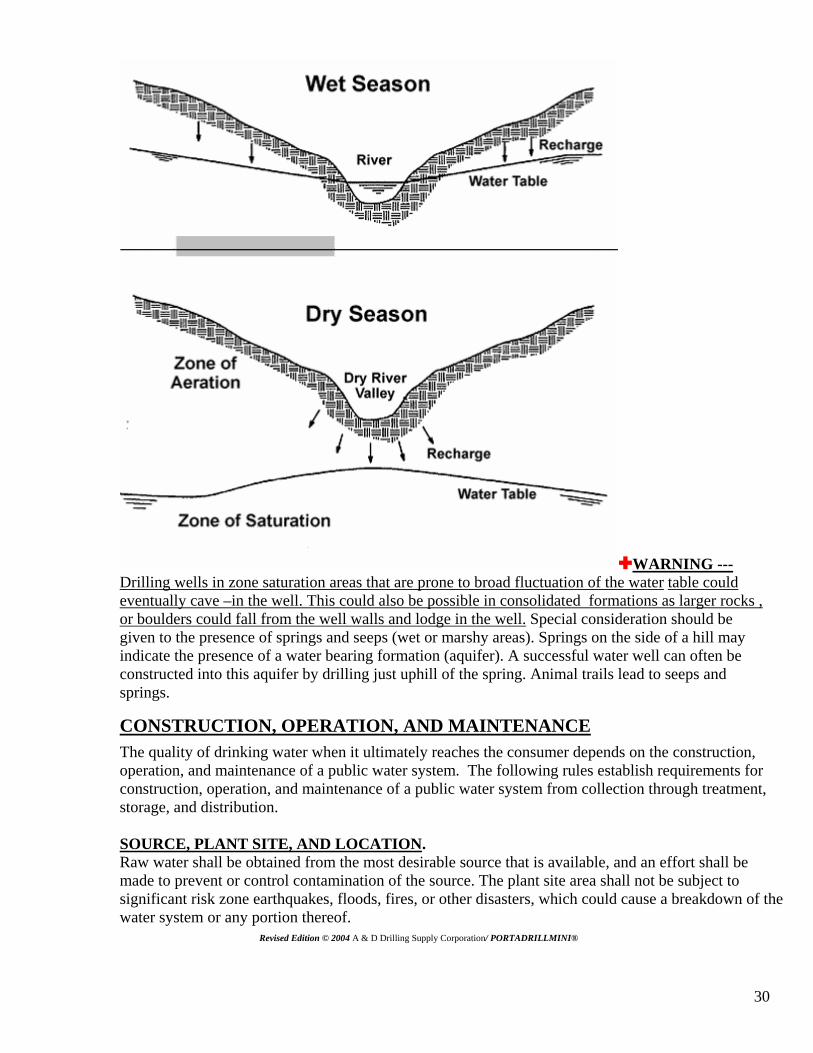
Good water wells can often be drilled near streams, lakes, rivers, ponds, and canals if the water well is deep, ground water may be available even if a river is temporarily dry. Reliable water wells have been located in or close to broad sandy riverbeds which are active once every 5-10 years. Water taken from wells located at least 50ft. (15 m) from a river is usually cleaner and cooler than the water taken from the river. If the well water remains turbid after construction and test pumping, the soils may be providing inadequate filtration and contaminated river water may be drawn into the well. Revised Edition © 2004 A & D Drilling Supply Corporation/ PORTADRILLMINI®
30
[WARNING ---Drilling wells in zone saturation areas that are prone to broad fluctuation of the water table could eventually cave –in the well. This could also be possible in consolidated formations as larger rocks , or boulders could fall from the well walls and lodge in the well. Special consideration should be given to the presence of springs and seeps (wet or marshy areas). Springs on the side of a hill may indicate the presence of a water bearing formation (aquifer). A successful water well can often be constructed into this aquifer by drilling just uphill of the spring. Animal trails lead to seeps and springs.
CONSTRUCTION, OPERATION, AND MAINTENANCE The quality of drinking water when it ultimately reaches the consumer depends on the construction, operation, and maintenance of a public water system. The following rules establish requirements for construction, operation, and maintenance of a public water system from collection through treatment, storage, and distribution. SOURCE, PLANT SITE, AND LOCATION. Raw water shall be obtained from the most desirable source that is available, and an effort shall be made to prevent or control contamination of the source. The plant site area shall not be subject to significant risk zone earthquakes, floods, fires, or other disasters, which could cause a breakdown of the water system or any portion thereof. Revised Edition © 2004 A & D Drilling Supply Corporation/ PORTADRILLMINI®
31
LOCATION OF PUBLIC DRINKING WATER WELLS
The following setback distances around public drinking water supply wells apply to newly constructed wells. 1) Public drinking water supply wells that serve water systems having total sewage flows greater than
2,000 gallons per day shall be placed no closer than 200 feet from on –site sewage disposal systems (septic tanks) other than land application of reclaimed water areas. Public drinking water supply wells serving water systems having total sewage flows of less than or equal to 2,000 gallons per day shall be placed no closer than 100 feet apart from on-site sewage disposal systems (septic tanks) other than land application of reclaimed water areas.
2) Public drinking water supply wells shall not be constructed within 300 feet of storage and treatment facilities (high intensity areas) of dairy farms.
3) Public drinking water supply wells shall be located no closer than 100 feet from other sanitary hazards.
4) Public drinking water supply wells shall be located on ground least subject to localizing flooding, and as far as is practical when direction of ground water slope or movement is known, wells shall be located on the upstream side of sanitary hazards.
5) The Department or appropriate water management district shall decrease or increase these distances when approving ,if justified , by the presence or absence of natural barriers such as impermeable geological strata adequate protection by treatment , or proper construction practices.
LOCATION OF POTABLE WATER MAINS
1) Water mains shall be laid at least ten feet horizontally from any existing or proposed sewer. Separation distances shall be measured outside edge to outside outside edge and shall not include any chord, radius, or diameter of the pipe. 2) Water mains shall be laid at least five feet (measured center to center) or three feet (outside to outside) from any reclaimed water line. 3) Where it is not practical to maintain the required separations, the department shall allow lesser clearances if the design engineer provides an engineering analysis.
DRINKING WATER SUPPLY WELLS OR TEST WELLS THAT MAY LATER BE USED FOR DRINKING WATER SUPPLY –NUMBER, CONSTRUCTION, CLEARING, DRILLING SAMPLES, AND ABANDONMENT. 1) Number of wells required – A minimum of two drinking water supply wells shall be provided for all community water systems that will serve 350 or more persons that have more than 150 connections. 2) Well construction
a) Access – every well shall be accessible for such attention as may be necessary. b) Casing Materials and Grouting Requirements The department before installation and use must approve 1.Casing and pipe.
32
2. Where telescoped casing is used, the casings shall be overlapped by not less than twenty feet where increases or decreases occur in casing size. Not less than two centralizing spacers shall be used in the overlapped sections, and the annular space in the overlapped sections shall be completely sealed with cement grout. A liner shall not overlap or telescope into the wall well casing and, therefore, a cement grout seal is not required for liner installation. 3. Casing for wells which obtain their water from a rock layer or other such consolidated formation shall, as a minimum, be seated firmly into it and sealed with cement grout by an approved method. 4. For well construction with driven casing, the minimum acceptable seal shall be accomplished by undercutting or under reaming the last five feet of the hole before seating the casing. A minimum of one foot of such enlarged hole must be into the consolidated formation in which the casing will be seated. The entire enlarged portion shall be filled with cement grout and then the casing driven through the grout to refusal. The upper twenty feet of casing shall be sealed with not less than a two-inch nominal thickness of cement grout. No other minimum seal shall be acceptable unless approved in advance by the water department. Any part of a well which is constructed by setting the casing in a previously constructed borehole which is of larger diameter than the outside diameter of the casing shall be sealed by filling the annular space from bottom to top with cement grout. Grouting methods and minimum standards shall at all times conform and a minimum set time o twelve hours is required. 5. The top of the casing shall be constructed to exclude any intrusion of surface water, for level areas, well tamped or puddled earth shall be placed around the well to elevate the concrete platform or apron. The apron must be a minimum 4” thick and 6’ by 6’ around the well. Before emplacing the pump(s) at the well(s) shall be protected at all times by a sanitary seal, threaded caps, or a welded flange to prevent entrance of contaminating material. c) Housing of well pump. Both well and pump shall be protected by a housing of
adequate size having an impervious floor and weatherproof walls and roof; however, completely weatherproof or submersible installations need only be protected
from tampering and vandalism. d) Well vent. Where provided, well vents shall be adequately protected. e) Sampling tap. A conveniently accessible, down- opening, smooth nosed, sampling
tap, located a minimum distance of twelve inches above the ground surface, shall be provided on the discharge side of each well pump on the upstream side of the check valve before the chlorine injection point so that samples of raw water may be obtained from the well.
f) Dynamiting of wells. The use of dynamite or other explosives in the well construction or maintenance of wells is prohibited.
g) Infiltration galleries, etc. dug wells, infiltration galleries and other such sources of water supply requiring rearrangements of natural features are prohibited as a source of public water supply unless water is filtered and disinfected.
h) Cleaning. Water supply wells are to be cleaned of any microbiological or other contaminant from well drilling activities so that the true microbiological character of the well water can be determined.
h-1) Every well shall be equipped with an opening in the casing which will allow introduction of disinfecting agents and the measurement of static water level, drawdown, or artesian pressure.

33
h-2) Before a new well or one suspected of being contaminated, or which one hat has been repaired is placed in use, it shall be pumped clean with the permanent pump and it shall be disinfected in accordance with an applicable method of “ American water works association standards or a comparable method approved by the Department . h-3) Following disinfection , a bacteriological survey shall be conducted as set forth below. The samples of raw water from the well shall be submitted to the department or a laboratory certified by the department of health for bacteriological analysis. The well shall not be used until the bacteriological survey is done and the department receives satisfactory results of the analysis.
1. After pumping the well until no trace of the disinfecting agent can be found, daily samples for 20 or more consecutive work days shall be collected after pumping the
well for 20 to 30 minutes at the rated capacity of the permanent pump each consecutive day. The daily samples shall be handled in accordance with acceptable methods. No more than two samples, at least 6 hours apart, shall be collected per day.
2. Interpretation of laboratory results from the bacteriological survey shall take into consideration details of the well construction, the presence or absence of surface protection, the age of the well relative to possible condition of the casing, the well log, or other pertinent information or conditions. However, where chlorination is the only treatment proposed, samples with coliform densities greater than four per 100 milliliter shall not exceed 10 percent of the total number of samples analyzed.
3. Drilling samples. A log completion report showing various strata pierced by the well and a detailed drawing of the well construction shall be forwarded by the well contractor to the water department or appropriate department office within thirty days after the completion of the drilling operation. In addition, the well contractor to the department shall submit the department may require cutting samples taken at 25-foot intervals and other information that. Samples shall show material in which the casing is seated. Blank well completion reports and forms and information on availability of sample bags may be obtained from the water department.
4. Abandonment. Al l abandoned wells shall be plugged by filling them from the bottom to the top with neat cement grout, unless otherwise approved in writing by the department.The plugging shall be to restore or improve the hydrologic conditions that existed before the well was constructed. Capping the casing top is prohibited. A letter to the department may do request for approval for abandoning a well(s). The letter requesting approval shall, at a minimum, contain the following information: a) location and size of well, b) length of casing of well, c) total depth of well, d) water level in well, and e) methods and materials used for plugging well.
PROHIBITION ON USE OF LEAD PIPES, SOLDER AND FLUX.
1. The installation or repair of any public water system or any plumbing in a residential or non-residential facility providing water for human consumption that is connected to a public water system shall be lead free. This section shall not apply to leaded joints necessary for repair of cast iron pipes. 2. Definition of lead free – for purposes of this section, the term “: lead free” shall mean: (a) when used with respect to solders and flux refers to solders and flux containing not more than 0.2 percent lead and (b) when used with respect to pipes and pipe fittings refers to pipes and fittings containing not more than 8.0 percent lead.
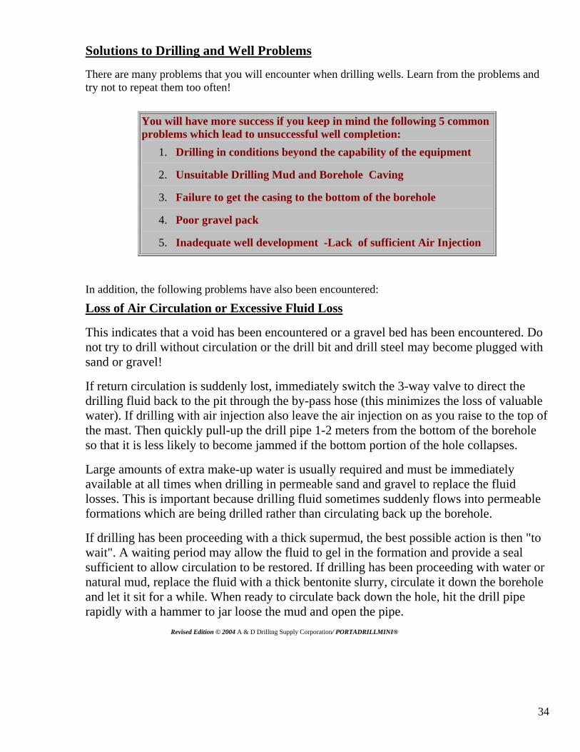
34
Solutions to Drilling and Well Problems
There are many problems that you will encounter when drilling wells. Learn from the problems and try not to repeat them too often!
You will have more success if you keep in mind the following 5 common problems which lead to unsuccessful well completion:
1. Drilling in conditions beyond the capability of the equipment
2. Unsuitable Drilling Mud and Borehole Caving
3. Failure to get the casing to the bottom of the borehole
4. Poor gravel pack
5. Inadequate well development -Lack of sufficient Air Injection
In addition, the following problems have also been encountered:
Loss of Air Circulation or Excessive Fluid Loss
This indicates that a void has been encountered or a gravel bed has been encountered. Do not try to drill without circulation or the drill bit and drill steel may become plugged with sand or gravel!
If return circulation is suddenly lost, immediately switch the 3-way valve to direct the drilling fluid back to the pit through the by-pass hose (this minimizes the loss of valuable water). If drilling with air injection also leave the air injection on as you raise to the top of the mast. Then quickly pull-up the drill pipe 1-2 meters from the bottom of the borehole so that it is less likely to become jammed if the bottom portion of the hole collapses.
Large amounts of extra make-up water is usually required and must be immediately available at all times when drilling in permeable sand and gravel to replace the fluid losses. This is important because drilling fluid sometimes suddenly flows into permeable formations which are being drilled rather than circulating back up the borehole.
If drilling has been proceeding with a thick supermud, the best possible action is then "to wait". A waiting period may allow the fluid to gel in the formation and provide a seal sufficient to allow circulation to be restored. If drilling has been proceeding with water or natural mud, replace the fluid with a thick bentonite slurry, circulate it down the borehole and let it sit for a while. When ready to circulate back down the hole, hit the drill pipe rapidly with a hammer to jar loose the mud and open the pipe. Revised Edition © 2004 A & D Drilling Supply Corporation/ PORTADRILLMINI®
35
If waiting and thickening the drilling mud do not restore circulation, question why the circulation was lost. If the drilling fluid is being lost into a highly permeable saturation formation, it may be possible to construct an excellent well! Therefore, test the well yield gallons per minute before deciding to proceed with the steps outlined below. If a gravel pit has been encountered do not attempt to drill through the gravel pit! This will result in Drill bit jamming!
It is possible that a void or a cave has been penetrated which could possible be to your advantage as voids sometimes are filled with water. Careful examination and testing could result in satisfactory gallons per minute yield from the void.
If it is necessary to drill further, try adding thickening materials to the drilling mud. This may occur when extremely unstable formations or those containing open fractures are encountered. Almost any granular flake or fibrous material can be used to provide a wad to block a lost circulation zone. Local materials such as bran, husks, chaff, straw, bark, wood chips, cotton, feathers, or even fibre or wool bedding can usually be located readily and used . This material should be pushed down the hole and allowed to block the fractures.
The "gunk squeeze" method of sealing off a zone of lost circulation involves forcing a large amount of clay or cement into the zone of water loss (usually at or near the drill bit) and forcing it into the formation where it swells and fills-up any cracks. A very high concentration (6 - 7 kg/L) of bentonite is mixed and immediately lowered into the borehole in a sealed bag or container which can be ruptured when opposite the lost circulation zone. Force the material into the formation by pressurizing the borehole or by pushing it with a block on the end of the drill string.
If the lost circulation zone cannot be blocked, drilling sometimes may proceed without return circulation. The cuttings are carried away into the formation cavities. It may be necessary to occasionally pump a slug of thick mud to clear the bottom of the hole. Gravel pits can be successfully drilled and evacuated if circulation is regained above the zone of the gravel pit and slowly drilled to allow evacuation of gravel. This also can result in a favorable void being formed that has a high gallons per minute yield if you are in under the water table . Care must be taken that this is not a void that is just above the water line . Alternatively, casing can be placed to seal-off the problem zone. Ensure that the hole has fully penetrated the problem zone which is to be protected by the casing; Running the casing too soon may not overcome the problems for long. Finally, if none of these options work, it may be necessary to abandon the hole or to continue drilling using air injection only if circulation can be maintained.
Preferred casing that can be driven to refusal is steel. Drive the casing till it is fully seated into a solid formation or until refusal. Revised Edition © 2004 A & D Drilling Supply Corporation/ PORTADRILLMINI®
36
WARNING
Do not attempt to drive or hammer plastic or PVC casing as it may shatter.
Sometimes direct push force of PVC or plastic casing into an open borehole can be successful but not hammered. Direct force casing most cases will not have a good seal at the bottom of the pipe and must be grouted before proceeding. It is not recommended to proceed to drill inside PVC or plastic casing as the walls could be damaged or cracked by jammed rocks inside the casing or can jam and result in rotation of the casing inside the bore hole.
Stuck Drill Steel and Drill Bit Jamming
Stuck Drill Steel and Bit can indicate that the borehole has collapsed or has caved in underground. Or perhaps a rock fell from the borehole walls.
The Drill Steel and Bit may become stuck or jammed when the injection air or if using drilling fluid is not allowed to thoroughly clean the borehole prior to stopping to add another joint of Drill Steel or the fluid is too thin to lift gravel from the bottom of the borehole. Remember the deeper you drill the more time should be allowed for the drill cuttings to exit the borehole. You can actually drill in some cases faster than the cuttings can exit the borehole and this will cause drill cuttings to stack on top of the drill bit resulting in rotation drag robbing usable horsepower available at the Drill Bit. This WILL limit your ability to drill deeper if there is a dramatic loss in horsepower from Rotation Drag. Therefore, if the drill bit starts to catch when drilling, stop further drilling and allow the injection air or drilling fluid to circulate and remove accumulated cuttings from the borehole. The drill cuttings usually will stack on top of the bit and will hinder the operation of expelling the cuttings or “Loss of Circulation” of injection air or fluids completely. Raise the Drill Steel to the highest position in the mast then wait until the drill cuttings are removed or becomes more thinner from water or cleaner looking indicating the drill cuttings have exited the borehole. You will notice the size of the drill cuttings getting smaller indicating the well bore is cleaner. If there is still large cuttings wait till you see a noticeable difference . Then continue to drill at a slower rate. If it continues to catch, thicken the drilling fluid.
Revised Edition © 2004 A & D Drilling Supply Corporation/ PORTADRILLMINI®
37
If the Drill Bit and Drill Steel become jammed, stop drilling and circulate drilling fluid until it is freed. If circulation is blocked, try to winch the Drill Bit and Drill steel out of the borehole. Stop the engine . Do not shut off injection if you still have circulation! Use a pipe wrench to reverse rotation (no more than 1 turn or the rod may unscrew!). Rapidly hit the Drill Steel with a hammer to try and jolt the bit free. Occasionally a rock may have fallen from the borehole wall and can jam the Drill Bit and Drill Steel. If the Drill bit becomes jammed , turn off the engine and turn the Drill Steel with a pipe wrench . Also work the Drill Steel in the reverse direction being careful not to unthread the Drill Steel. The back and forth motion should free the jammed or stuck Drill Bit and then proceed by using the rotation of the engine. Do not attempt to repetitively use the engine torque to free the stuck Drill Steel. Caution should be taken as to not overheat the clutch. Use the pipe wrench with the aid of a leverage pipe.
If you still have rotation but you are still stuck occasionally you can free the stuck drill bit by rotating the drill bit with no injection to allow the rock to fall past the drill bit . When you do regain and are not stuck turn injection air or fluid s on slowly as to not blast or explode the walls of the borehole to cause a collapse. Also opening the injection air or drilling fluids to quickly can cause a burst to come out of the borehole under pressure and onto the operator and the machine.
If these actions are not successful, use lengths of Drill Steel without a Bit attached or Wattera tubing to "jet out" the borehole cuttings. Attach the pipe or tubing directly to the discharge hose from the mud pump. Thicken the drilling fluid to ensure that the cuttings holding the bit can be removed. Then place tension of the stuck Drill Steel with the PORTADRILLMINI ® winch. Once fluid starts to circulate out of the borehole, slowly push the jetting pipe/tubing down the borehole beside the jammed Drill Steel until the bit is reached. When fluid starts to circulate out of the stuck pipe and/or it loosens, pull the stuck Drill Steel and resume circulation of the thickened drilling fluid back down the Drill Steel and Bit. Remove the jetting pipe. If water freely circulates out the borehole, slowly lower the Drill Steel and bit and resume drilling. To insure that all drill cuttings have exited the bore hole , raise the engine to the top of the Drill Mast and slowly let down to insure that the hole still remains open before stopping to add more drill steel. If the drill bit stops on the way down to the bottom this indicates there is still drill cuttings in the borehole. This also can be done with no rotation with the engine at idle, and if it passes freely from top to bottom with out stopping you may proceed to add another piece of Drill Steel. When you are at the bottom slow the injection air or fluids while unthreading the drill pipe only to turn it completely off when disconnecting and raising the engine. This helps to equalize the pressure in the borehole before you would suddenly turn off injection and also insures that the Drill Steel is not plugged during the process of changing Drill Steel. Revised Edition © 2004 A & D Drilling Supply Corporation/ PORTADRILLMINI®
38
Resistant Beds Encountered This would indicate a change in rock formation and or density of the rock formation. If the rock formation can be identified it may then indicate the change of the type of drill bit used to drill that particular rock formation . Once a resistant bed is encountered and the rate at which the drill bit is penetrating the formation drops dramatically, a decision needs to be made whether to stop drilling or to continue. If the resistant bed is comprised of gravels, the drilling fluid may need to be thickened to lift-out the cuttings. If the resistant bed is hard granite, drilling with the PORTADRILLMINI © Drill should be done with an alternative drill bit or should cease. Other drilling methods should be found or smaller drill bits should be used to penetrate the formation first ,… possibly drilling should be attempted at another location. Remember, to help as many people as possible and to get the best value for the equipment , DRILL THE EASY BOREHOLES FIRST!! It is not worth wearing-out the drill unit or drill bits by grinding away for hours and hours to gain a foot or two of borehole depth. Not all boreholes are the same if the location is to be changed you need to be a minimum of 15 feet from the old bore hole to avoid crossover loss of circulation and or contamination from the old borehole. Abandoned boreholes must be sealed with grout to be abandoned properly and to avoid accidents in the future with open bore holes.
Tools or Objects Dropped Into Borehole
Unfortunately, sometimes wrenches, tools, pipe, rocks etc are inadvertently dropped into the borehole when drilling. Do not operate the PORTADRILLMINI ® Drill near its design limits with a high degree of structural stress on the drilling stems and tools; encountering unexpected layers of very soft sand or filter or hard rock can cause cave-ins or tool breakage and all the Drill Steel and Drill Bit can be lost in the hole.
If objects are dropped into the borehole after the final depth has been reached, it may be possible to leave them there and still complete the well. If this is not the case, it may be possible to make a "fishing" tool to set-up on the lost gear. Example, if a length of well screen falls down the borehole, it may be possible to send other sections down with a pointed tip on the end and "catch" the lost screen by cramming the pointed end hard into it. These types of "fishing" and recovery exercises require innovation and resourcefulness suitable to the circumstances - there is no single right way of doing this work. If sediment has caved in on top of the drill bit or other tools, circulation should be resumed in the hole and the fishing tool placed over the lost tool or gear .
If the lost tools/bit(s)/drill pipe are not critical, do not even try to retrieve them and just move over and start drilling a new borehole. Even if the equipment is important, it is still best to start drilling at a new location while others try to retrieve it since considerable time can be spent on retrieval and there is a low likelihood of success. Lost drill pipe in the bore hole can sometimes be retrieved by fishing the drill steel over the threads and retreading . This may take some patience and time depending on how deep the lost drill steel is at. Revised Edition © 2004 A & D Drilling Supply Corporation/ PORTADRILLMINI®
39
Casing Contaminated Soil/Water-Bearing Zones/ Voids
It is sometimes necessary to drill through aquifers which contain contaminated water. In these situations, drill until a confining layer (clay or rock) is encountered. Insert the casing and then seal the annular space with a grout slurry. To avoid damaging the grout seal, let the grout cure for at least 12-24 hours prior to resuming drilling .
Grout is prepared by mixing 19.7 L (5.2 gal) of water with every 42.6 kg (94 lb) sack of cement; 5 volumes grout slurry can be made by mixing 4 volumes cement powder with 3 volumes fresh water. Alternatively, each sack of cement can be added to a clay-water suspension formed by mixing 1.36 - 2.27 kg (3-5 lbs) of bentonite with 25 L (6.5 gal) of water. This mixture helps hold cement particles in suspension, reduces cement shrinkage, improves the fluidity of the mixture and prevents excessive penetration of grout into these formations.
Cement grout is normally placed by just pouring it into the annulus. Alternatively, some grout could also be poured into the casing and/or the casing could be raised several feet and then pushed into the grout that accumulates at the bottom of the borehole. Proper grouting is done from the bottom coming up the annulus in the bore hole .Place the grout in one continuous operation to form a good seal. Since irregularities in the size of the borehole and losses into formation may occur, the driller must be prepared to augment initial estimates of grout volume on short notice.
Where contamination is severe, follow special procedures to ensure that a very good seal around the casing is achieved. When you finish grouting, ensure that you leave about 0.5 metres of grout in the casing. Allow time for the grout to cure before drilling .
CAUTION ! Water inside the casing may be come scalding hot from the heat of the curing grout , care must be taken when restarting the drilling operation of hot water that may circulate out of the borehole. This usually occurs when large amounts of grout are used causing high heat .
FOOTNOTES 1 Ideally, for a 100-foot deep borehole drilled with the PORTADRILLMINI ® Drill , the settling pit should be 2.5 feet deep, 2.5 feet wide and 6.5 feet long; the suction pit should be 2.5 feet deep, 2.5 feet wide and 3.5 feet long. However, while these pits provide optimum settling capability, they require large quantities of water to be brought to the site. 2 If this is not done, the fins of the blade bit may disturb the borehole wall and cause silt/clay cuttings to "ball-up" or bridge within the borehole. In addition, drilling fluid may cause silts and clays (especially above the water table) to swell and bulge into the borehole. Getting the screen past these blockages can be very difficult and it is almost impossible to avoid severely plugging the screen. PORTADRILLMINI ® Drill is a Registered Trademark. Patent .#6,315,059 Revised Edition © 2004 A & D Drilling Supply Corporation/ PORTADRILLMINI®
40
Limited Warranty Neither the foregoing express warranty nor any other warranty by A & D Drilling Supply Corporation / PORTADRILLMINI ® , express or implied , is applicable to any item A & D Drilling Supply Corporation / PORTADRILLMINI® sells which is warranted directly to the user by its original manufacturer . This warranty is expressly in lieu of any other warranties, expressed or implied, including any warranty of merchantability or fitness for a particular purpose . Remedies under this warranty are expressly limited to the provision of material and services as specified herein. A & D Drilling Supply Corporation / PORTADRILLMINI ® is not responsible for special , indirect , unforeseen incidental or consequential damages or other economical loss, monetary and contractual loss , civil loss, whether arising in contract or tort , arising out of the use of , or inability to use , products covered by this warranty . Due to the fact that drilling conditions can vary unpredictably from one drilling site to the next, we can’t promise or give statements how fast or deep you will drill at any specific drilling site with any specific drill bit diameter size. Examples expressed are from research and development prototype results. This warranty and A & D Drilling Supply Corporation / PORTADRILLMINI ® liability hereunder is limited to the repair or replacement of failed components, as A & D Drilling Supply Corporation / PORTADRILLMINI ® may elect at an establishment authorized by it , of such parts as shall appear to A & D Drilling Supply Corporation./ PORTADRILLMINI® , upon inspection , to have been defective in material or workmanship , but does not include any installation or transportation cost . This warranty does not apply to normal maintenance service or to normal replacement of service items. No warranty is made with respect to items made by others when such items are warranted by their respective manufacturers or when they are supplied by A & D Drilling Supply Corporation /PORTADRILLMINI ® on special order. No recommendation of items made by others shall imply or constitute any warranty with respect to such items. Revised Edition © 2004 A & D Drilling Supply Corporation/ PORTADRILLMINI®