68 inch yak-54
TRANSCRIPT

68 INCH
YAK-54
Instruction Manual

Thank you for your purchase of the Extreme Flight RC 68 inch Yak-54. Please take a few moments to read this instruction manual before beginning assembly.
We have outlined a fast, clear and easy method to assemble this aircraft and familiarizing yourself with this process will aid in a quick, easy build.
Please read the following paragraph before beginning assembly of your aircraft! THIS IS NOT A TOY! Serious injury, destruction of property, or even death may result from the misuse of this product. Extreme Flight RC is providing you, the buyer with a very high quality model aircraft component kit, from which you, the buyer, will assemble a flying model. However it is beyond our control to monitor the finished aircraft you produce. Extreme Flight RC will in no way accept or assume responsibility or liability for damages resulting from the use of this user assembled product. This aircraft should be flown in accordance to the AMA safety code. It is highly recommended that you join the Academy of Model Aeronautics in order to be properly insured, and to operate your model at AMA sanctioned flying fields only. If you are not willing to accept ALL liability for the use of this product, please return it to the place of purchase immediately. Extreme Flight RC, Ltd. guarantees this kit to be free of defects in materials and workmanship for a period of 90 days from the date of purchase. All warranty claims must be accompanied by the original dated receipt. This warranty is extended to the original purchaser of the aircraft kit only. Extreme Flight RC in no way warranties its aircraft against flutter. We have put these aircraft through the most grueling flight tests imaginable and have not experienced any control surface flutter. Proper servo selection and linkage set-up is absolutely essential. Inadequate servos or improper linkage set up may result in flutter and possibly the complete destruction of your aircraft. If you are not experienced in this type of linkage set-up or have questions regarding servo choices, please consult an experienced pilot or contact us. It is your responsibility to ensure the airworthiness of your model. Additional items needed to complete assembly. .91-1.40 2 stroke or .91-1.50 4 stroke engine 3” spinner (We used a Tru-turn 2 7/8” Ultimate on our prototype) Propeller 4 channel radio with five 90+ oz. in. torque servos for control surfaces and one standard torque servo for throttle. We used the Hitec 5645 digital servos in our prototype. Servo arms (we highly recommend the Du-bro Super Strength servo arms for this aircraft). Fuel tubing Foam padding for receiver Nylon cable ties or Velcro straps Servo extensions (see text for proper lengths)
2

A few words about the Extreme Flight RC 68” Yak-54 The current production version of the 68” Yak-54 represents a milestone in ARF model aircraft production techniques and performance ability. This version is the result of a lot of time and effort testing various configurations and materials to achieve the lightest, yet strongest airframe possible. Ultra-modern interlocking laser cut construction techniques combined with carbon fiber and composite components help to achieve a lightweight, yet robust airframe. Each component of the Du-bro hardware package was selected because of the high quality associated with these products. These components have been proven over a year of very aggressive flight testing. We highly recommend that you use the included hardware. We are very proud of the high quality Oracover finish on this aircraft, as well as the beautiful, perfectly matched paint job on the cowl. The extremely lightweight wheel pants are white gel-coated to eliminate the need for paint, thus saving weight. In an airplane this size, every gram counts. We hope you will consider this during your assembly of this aircraft. Resist the urge to “beef-up” the structure and use caution when applying glue, using only the proper amount needed for the task. Flight performance of the 68” Yak is simply stunning! It tracks through precision maneuvers much like a fine tuned pattern ship, easily performing any of the F3A or Unlimited class IMAC schedules. The 3D performance of the Yak is unheard of in a plane this size. The 68” Yak-54 is truly unlimited in its performance capabilities. By the time the Yak arrives in your shop, it will have endured several climate changes. As a result you may find some wrinkles in the covering. This is not a manufacturing defect. Please take a few moments with your iron or heat gun and remove any wrinkles. Iron over all the edges to ensure they are sealed. A high quality vinyl graphics package has been included with this aircraft. For best results it is highly recommended that you spray the surface of the aircraft where the graphic is to be applied with Windex or a soap/water solution to allow for proper positioning of the graphics. When satisfied with their position, use a credit card or rubber squeegee to remove excess fluid from under the graphic and allow to dry overnight. It is highly recommended that you keep your aircraft under a shelter, away from direct sunlight between flights, or use some form of cover to prevent damage to the canopy/hatch. Intense heat from the sun can distort the canopy/hatch, and you want to take caution to prevent this from happening.
3
ATTENTION!
Due to a communication error, there are some extra hardware components included with this aircraft. In addition to the Du-bro hardware package located next to the cowl, you will find a second hardware package in the cardboard divider containing the composite landing gear. You may choose to discard this metric hardware, but there are five components in this hardware package that are essential to the assembly of this aircraft. Please do not discard the following items:
1. Four carbon fiber anti-rotation pins. 2. Nylon engine mount. 3. Tailwheel assembly. 4. Throttle linkage. 5. CA hinges. Also please note that the 4-40 pushrods have been taped to the cardboard divider separating the cowl from the fuselage. Do not discard.
4

WING ASSEMBLY
1. We will begin by hinging the aileron to the wing. There are 7 CA hinges that will be installed per wing/aileron. Use a ruler and measure from the root (closest to fuselage) of the aileron to the tip and locate the hinge slots, then slit the covering to access the slot (already cut) for the hinge. The following are the hinge slot locations from the aileron root. NOTE: All hinge slots are in the center of the bevel on all surfaces. 1. 1 ¾ 2. 7 ½” 3. 11 ½” 4. 13 ½” 5. 17 ½” 6. 22 ½” 7. 28 ¼” Now transfer the slot locations to the wing. Install the hinges halfway into the wing, then mate the aileron. Be sure the hinges stay centered. Refer to figure 1. TIP: To aid in keeping the hinges centered I insert a t-pin or draw a line in the middle of the hinge.
Figure 1
2. We will now glue the CA hinges using thin CA. Be sure that the aileron stays
mated to the wing, do not allow more than 1/16” gap while gluing. I like to bend the surface about 40° each direction while gluing. Apply glue to both sides of the hinge, this method will also be the way we do the rudder and elevator hinging later in the assembly process. Refer to figure 2 for my method, also you will notice I have an extended tip on my CA glue bottle, this allows me to get the glue in the exact area.
5

Figure 2
3. Locate the servo bay (bottom of wing near center) under the covering by feel, once located cut the covering to expose the opening. You will need a 6” or 12” wire extension hooked to your servo lead so it will be able to go inside the fuselage once the wings are installed to reach the receiver. Feed your servo wire thru the wing to the root and let it protrude. See figure 3.
Figure 3
6

4. Secure your servo in the wing’s mounts with the output shaft closest to the
hinge line. Measure on the bottom side, at the root of the aileron 11 ½”, you will feel a small hole under the covering where the 6-32 control horn bolt will be located, remove the covering from this hole. Locate the control horn package and use one of the 6-32 bolts and black mounting plate (with circle hole on the top for the bolt head to set down into it). Insert the bolt thru the mounting plate and screw the bolt down into the topside hole, you may need to drill the hole to 9/64”. Now secure the other mounting plate with hex nut onto the bottom side and tighten. Take the 4-40 all thread rod and cut a piece 1 ½” long and install the 4-40 jamb nut and clevis to one end allowing about 2 – 5 threads showing thru the clevis. Hold the control surface centered, also make sure the servo arm is parallel to the hinge line and install the other jamb nut and clevis to the servo arm. Use a thread locking compound to secure jamb nuts. Refer to figure 4.
Figure 4
5. Locate the package with the carbon fiber alignment pins, use two of them per wing. The alignment pins fit into the two smallest holes in the wing root. Trial fit before gluing. Using 30 minute epoxy lather all but ¼” of the pin and apply some epoxy inside the hole. Insert the pin into the hole and there is another hole in the number two rib that the pin will go into also. Leave about ¼” of the pin
7

without epoxy protruded from the wing, allow to dry. Take the included ¼” X 20 plastic wing bolts and cut them to ¾” long from the bottom of the washer head. Refer to figure 5, it will show how the wing root will look when completed. From left to right you will see the first alignment pin, then the carbon fiber wing tube location, followed by the wing bolt, then the aileron wire and finally the rear alignment pin. Repeat these 5 steps on the other wing panel. This will complete the wing assembly. Figure 5 shows the wing completed at the root.
Figure 5
FUSELAGE ASSMEBLY
6. Locate the gear, 4 of the 6-32 X ¾” bolts, washers and nylonHold the gear, with the slant forward, to the fuselage bottom in thcenter it. Now mark the location of the bolt holes onto the gear frofuselage, drill the holes slightly larger than the bolt. It is highly rethat you place a wood block behind the gear before drilling to prethe rear side of the gear when the drill bit exits. Install a washer oslide the bolt from the gear’s bottom up into the aluminum gear mnylon insert nut onto each of the 4 bolts and tighten. See figure 6
8
Alignment pins Servo wire Wing bolt
insert hex nuts. e gear slot and m inside the
commended vent damage to n each bolt and ounts. Secure a and 7.

Figure 6
7. Trim the covering around the wing slot, estabilizer locations. EF suggests that you lea(see figure 8) and iron that into the slot. At thand iron into the slot. The elevator servo slot
Figure 8
8. Locate the horizontal stabilizer and bothslots using the same methods as the aileronsmeasuring from the tip of the horizontal inwa1. 1 ½” 2. 3 ¾” 3. 6 ¾” 4. 8 ¾” DO NOT GLUE THE HINGES AT THIS TIME
9
Figure 7
levator servos and horizontal ve 1/8” of covering at the wing slot e horizontal, leave 1/16” of covering s may be cut and ironed as desired.
elevators. First lets find th. The hinge slots will be f
rd to the root. See figure 1
1/8” covering left that may be ironed to inside of fuselage
e hinge ound by 2.

Figure 9
9. We will now prepare to mount the horizontal into the fuselage. First locate the exact center of the horizontal, next take the measurements of the front and back widths of the stabilizer slot in the fuselage and transfer those to the horizontal. Gently cut that covering making sure you do not cut into the sheeting and leave about 1/16” extra covering when finished. See figure 10.
10. Read and understand this step completely before proceeding. Install the wings onto the fuselage. You may dry fit the horizontal and find where it centers and mark it with tape or similar material or proceed with the gluing process. We will now glue the horizontal stabilizer into place, if you did dry fit the horizontal, remove it at this time. Mix ample 30 minute epoxy and apply to the inside of the fuselage slots and to the bare wood on the horizontal. There is no need to apply epoxy to the exact center of the horizontal, only the areas that will make contact. Have a cloth/paper towel soaked in rubbing alcohol ready, now slide the horizontal into the slot and center it in the fuselage. Wipe the excess epoxy with the cloth. Use a ruler to measure from a common point on each side of the horizontal to a common point on the fuselage to be sure it is centered. Prop the tail up so the fuselage is level and view the wing and horizontal from the front and back to make sure they are aligned. If the horizontal is not aligned, take some masking tape and pull one side up or down and tape it in place to hold it while the glue dries. Finally, you may add some glue to the inside thru the elevator cutout holes. Allow this to dry completely before proceeding. Refer to figures 10, 11 and 12 to help with this important step. Hinge both elevators.
10

In this picture I have located the center and cut the covering away but, have left 1/16” extra to keep bare balsa from showing. At this point the horizontal should be ready to install.
Figure 10
I have now installed the horizontal with 30 minute epoxy and wiped the excess away. I now continue to center the horizontal by measuring each leading and trailing edge to be sure I have an equal amount of surface on each side of the fuselage. This will ensure I am centered, but not necessarily aligned.
Figure 11
11

I now tip the plane onto its nose and view it from behind to be sure I am parallel with the wing. In figure 11 you will notice the tail is propped up onto a box to make it level. You may use that method to view it from the front and back to be sure the tail is aligned with the wing.
Figure 12
11. Next we will install the tailwheel, locate that package. Hold the mounting bracket onto the bottom rear flat spot on the fuselage such that the wire “L” portion will be able to insert itself into the rudder later in the process. Drill small pilot holes and install the wood screws. Position the tail wheel onto the wire and file a flat portion on the outer side of the wheel. This allows the wheel collar to have a flat spot to drive the setscrew against. See figure 13 and 15.
Figure 13
12

12. Take the rudder and locate the hinge slots in the same manner that we did the ailerons. The following are the measurements for the hinge locations, measure from the bottom upwards on the rudder. (There are four slots. 1. 1 ½” 2. 4” 3. 6 ¾” 4. 9 ¼” See figure 14.
Figure 14
Dry fit the rudder to the fuselage and mark a spot where the tailwheel will go into the rudder, drill that hole. TIP: You may cut a small groove in the front of the bevel at the bottom of the rudder to accommodate the wire tail wheel. Now hinge the rudder using the same technique we did with the ailerons, be sure to observe the same precautions. See figures 14 and 15.
13

Figure 15
13. Now lets install the elevator servo. Attach a 12 – 18” extension to the servo and fit into either bay to begin. Secure the servo with mounting screws. Use the same techniques in step 4 to install the control horn and pushrod with clevis. Cut the 4-40 all thread so you have two 4 ¼” pieces. Refer to figure 16.
The small groove may be cut here. Here is the tail wheel assembly.
Elevator control horn location.
Output shaft closest to the horizontal. 4-40 all thread that’s 4¼” long. Jamb nut secured against the clevis. Figure 16
This is the hole for the 6-32 control horn. This will be later in the assembly process.
Do the same for the installation of the other elevator servo.
14

TIP: You may run your servo wires thru the fuselage formers to the receiver. This will aid to keep them secured during flight.
14. The rudder runs on a pull pull set up that is very easy to install. Lets begin by mounting the servo in the rails just under the canopy. Again, we will mount our servo with the output shaft towards the tail, secure with screws. Locate the hardware package containing all the items for the rudder system. Cut a piece of coated wire 36” long, this will give you approximately 5” extra on each end. Just above the elevator servos there is ¼” tall by 6” long slot, that can be seen inside the fuselage from the canopy area. Open this slot, you may iron it to the inside if you wish. Locate the hard point in the rudder. It can be found by measuring from the bottom of the rudder upwards to a point 3 3/8” (see figure 15) and you will feel the hole under the covering. Drill this hole using a 9/64” bit and install the precut 3 ¾” all thread into the hole leaving equal amounts on each side of rudder. Slide the cupped washer onto the all thread, then the cone shaped nut followed by the hex nut and tighten (thread lock is permissible), do this to both sides. Finally thread the clear horn onto the all thread to the desired distance on both sides. Feed the coated wire thru the slot and towards the servo leaving some on the outside of the fuselage to secure to the rudder horn. Cut a piece of heat shrink tubing about ¾” to 1” long. Slide this tubing onto the wire, then the crimp and then the rigging coupler and back thru the crimp leaving about 1/8” wire beyond the crimp. Use a pliers or similar and squeeze the crimp flat. Slide the heat shrink over the crimp and part of the rigging coupler and shrink it with a heat gun. Feed a hex nut and clevis onto the rigging coupler, tighten and secure it to the horn. Proceed to the servo and finish it there in the same manner, be sure the servo is centered before cutting the excess wire to its final length. Do the other side of the pull pull using the same procedures. See figures 17 and 18. TIP: The rudder hardware package also has installations recommendations.
15
Figure 17 Heat shrink Crimp Rigging coupler 2/56 clevis Jamb nut

NOTE: In figure 17 the heat shrink has not been slid onto the crimp and rigging coupler and has not been shrunk. This shows it before shrinking.
Cupped washer Cone nut Hex nut Clear control horn
Figure 18
15. In this step we will mount a YS 110 engine, although other motors would
work EF feels the best performance will be attained with this engine choice. Therefore, all measurements will be with regard to the YS 110, but check them before you make the final mount to be sure there are no abnormalities. NOTE: Pumped engines, such as the YS 110, should be mounted inverted, non-pumped engines should be side mounted. Locate your engine mounts, (4) 6-32 X 1” bolts, washer and blind nuts, (4) 8-32 X 1” bolts, washer and lock nuts. The goal is to have your engine protruding from the front of the cowling by ¾” (that is the front of the cowling to the back plate). With the YS 110 you will need to measure from the front of the black engine mounts ¾” back and make a reference mark. This will be where the front of the engines mounting bearers will align.
16. The hole in the firewall represents the center of the fuselage. You will need to find the location for your engine mounts using the hole as your benchmark for measurements. For the YS 110 here is how to find the location for your mounts. The firewall has 3º right thrust already built into it, therefore your final mounting spot will be offset to the left half of the firewall. Refer to figure 19 for measurements, if using the YS 110 these measurements will give you the correct engine mounting position. Other brand engines you may use the vertical and horizontal centerline marks and then reference your specific engine dimensions from these centerlines.
16

Figure 19
This vertical centerline is 2 5/32” from the side. This horizontal centerline is 2 1/32”from the top. This mark is 9/32” from the vertical centerline and should be used to center engine. The right engine mount is 1” from the right side.
17. Hold one of the mounts to the firewall on the inside of the 1’ line. The side
of the mount has a reference mark in the center of the mount, use it to center it vertically (see figure 20, I used masking tape to highlight the mark). Once you are satisfied with the location, drill the top and bottom holes. I now mount the engine to the one mount (read tip below) and then bolt it to the firewall with the 6-32 bolts and blind nuts. The shank of the blind nut may protrude through the front of the firewall. Open the hole in the rear of the engine mount to accommodate the protruding shank. Now take your other engine mount and hold it in place to the other side of the engine and mark the holes for the firewall and engine boltholes. You may now finish the mounting process. TIP: We like to drill and tap the fiberglass engine mounts plus use the provided nylon insert nuts to secure the engine to the mounts.
17

Figure 20
20. Locate the cowl, 4 #4 bonded sealing washers and socket head mounting screws. The YS 110 will stick thru the bottom of the cowl so you will need to trim as desired. (EF also recommends cutting out the bottom portion only of the oil cooler located on the very bottom of the cowl for proper cooling.) The cowl needs to go onto the fuselage until it is 1/8” in front of the wing slot in the fuselage. Now center the cowl in reference to your engine shaft/back plate. There are four fingers that protrude from the front bulkhead that will secure the cowl, drill your holes into the center of these and use the provided screws and bonded sealing washers to hold the cowling. See figure 21.
18

Figure 21
21. Locate the tire/wheel pant hardware package. Begin by inserting the 6-32 X
1 ½” bolt thru one tire, followed by a #6 nylon washer and nylon insert nut (locknut), tighten the nut but leave it loose enough that the tire spins freely. Drill a 9/64” hole in the landing gear about 3/8” up from the bottom and centered. Insert the tire axle assembly into the hole and install a washer/locknut and tighten, see figure 22. Take the wheel pant and file out enough of the slot on the side so it will slide onto the locknut that is closest to the tire. (It will slide onto the locknut similar in principle to the way an adjustable wrench fits onto a hex nut.) Take the time to make this a snug fit. Now slide the wheel pant onto the nut and over the tire, you may need to trim the outer side of the pant so it will fit. Now align the pant as you desire (EF suggests it be parallel with the fuselage) and drill a 7/64” hole (approximately ½”), above the axle bolt, be sure not to go too high or you will miss the plywood plate inside the pant. Remove the pant and insert the blind nut inside the pant as shown in figure 23. Reinstall the pant and trial fit everything together, make adjustments as necessary. Refer to figures 22, 23 and 24.
Figure 22
19

4-40 blind nut Slot that fits over locknut
Figure 23
6-32 locknut Slot fits over locknut
Figure 24
22. Assemble the fuel tank according to instructions and mount it onto the tray
in front of the wing tube. It can be secured with Velcro or nylon cable ties.
23. The throttle servo may be installed in the same tray as the fuel tank if you use a mini servo. There is a rod with prebent Z bend and housing that may be used to connect to the engine. The servo end has an EZ connector that may be
20

used. There are several areas this servo can be installed, however you may need to install hardwood to accommodate some areas. Figure 25 shows a mini servo installed in a hardwood stick mount just aft of the wing tube.
Figure 25
24. Secure a 4-40 blind nut to the backside of each hole on the hatch mounting plates. Locate the 4 holes in the side of the fuselage under the covering, each hole is under the yellow stripe. Remove the covering and use your 4-40x.5” bolts and bonded sealing washer and secure the hatch to the fuse in all four locations.
4-40 blind nut Figure 26
21

There are a total of 4 of these holes. Insert the 4-40 bolt/washer into each of these to secure the hatch for flight.
Figure 27
25. Mount your switch, battery and receiver in the fuselage, try to place the
receiver and battery pack to attain proper center of gravity ( CG range is from the front of the wing tube to one half inch behind the wing tube). Our prototype had the battery secured to the bottom of the tray that held the fuel tank and the receiver was secured to a fuselage former in the belly area with Velcro. Be sure to follow all radio manufacturers recommendations. Figures 28, 29 and 30 show how EF located one of our prototype’s radio gear.
22
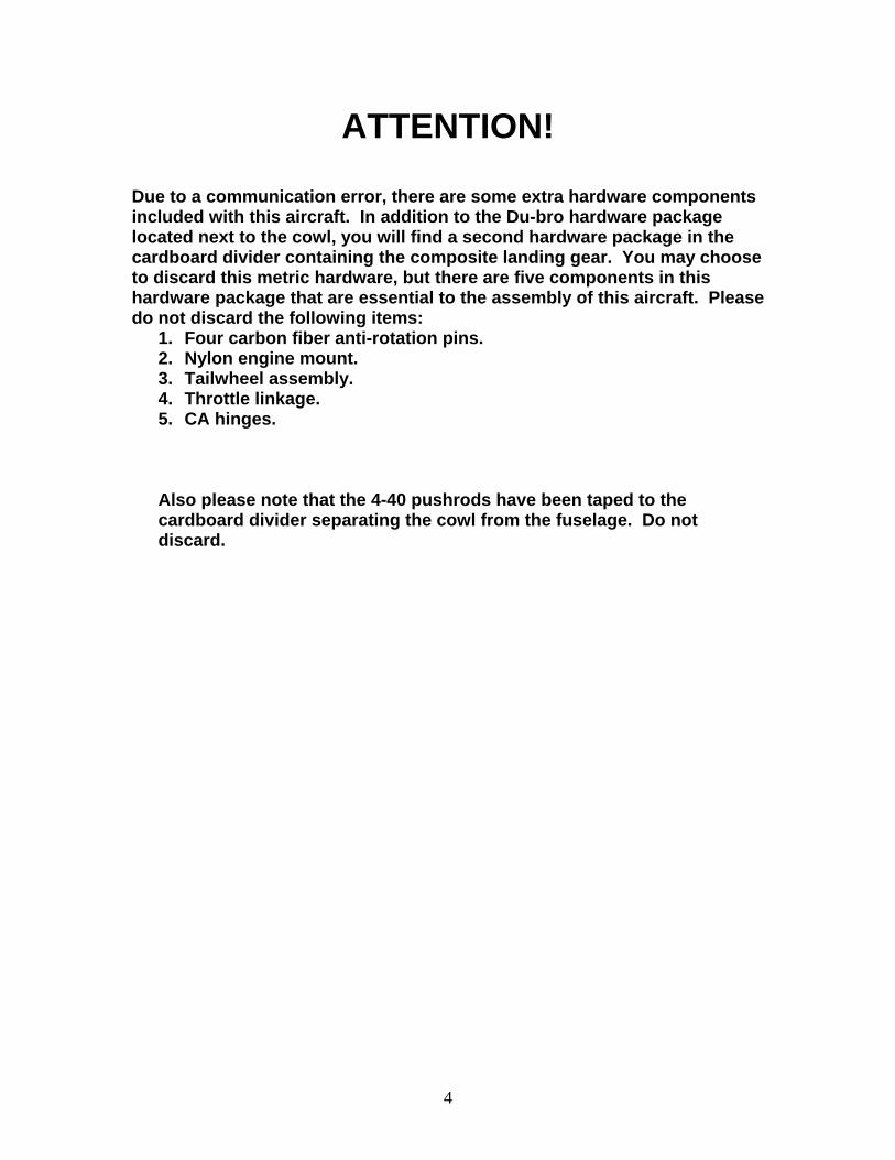
This is an optional Dubro #207 switch mount. It is located just behind the left wing. A charge switch such as the JRPA004 or Maxx products unit works well in this application.
This shows the inside of the switch mount. You will need to remove some foam to accommodate most switches. Figure 29
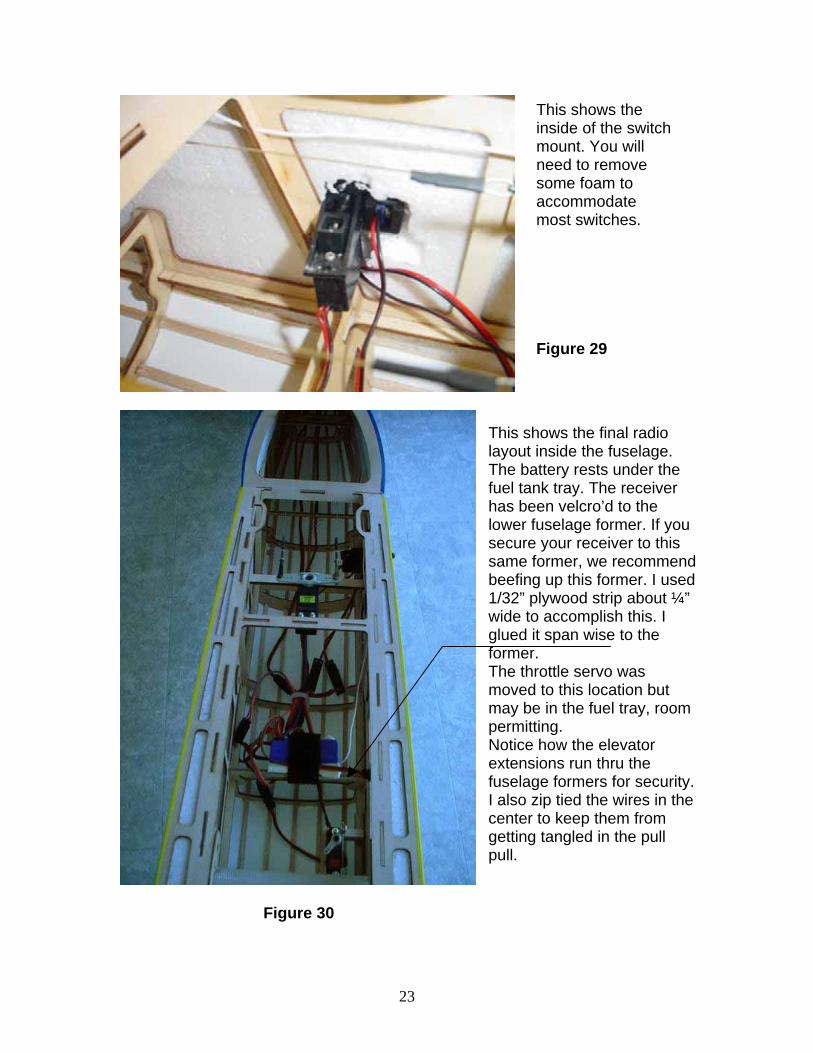
This shows the final radio layout inside the fuselage. The battery rests under the fuel tank tray. The receiver has been velcro’d to the lower fuselage former. If you secure your receiver to this same former, we recommend beefing up this former. I used 1/32” plywood strip about ¼” wide to accomplish this. I glued it span wise to the former. The throttle servo was moved to this location but may be in the fuel tray, room permitting. Notice how the elevator extensions run thru the fuselage formers for security. I also zip tied the wires in the center to keep them from getting tangled in the pull pull.
Figure 30
23

A few words about set-up and trimming Proper set-up and trimming is absolutely essential to achieve optimum performance from your aircraft. In addition to balancing your aircraft at the recommended CG position, we highly recommend that you balance the aircraft laterally. Use stick-on lead weight under the wing tip to achieve proper lateral balance.
We recommend the following control surface throws: Elevator: Low rate: 8 degress both directions High rate: At least 45 degrees both directions Ailerons: Low rate: 15 degrees both directions High rate: 35-45 degrees both directions Rudder: Low rate: 15 degrees both directions High rate: As much as possible
Depending on your personal preferences, you will probably want to use a fair amount of exponential to soften the feel of the aircraft around center stick position on high rates. The rudder on the Yak is extremely powerful. If you experience severe coupling in high alpha knife edge, you probably need to reduce your high rate rudder setting. The Yak is capable of very slow high alpha knife edge with minimal coupling. Experiment to find the setting that works best for you. If you are new to 3D or are having trouble locking in to high alpha flight, you may wish to mix a small amount of spoileron in with up elevator input. This will cause the ailerons to raise with up elevator input and will help to stabilize the aircraft in high alpha attitudes. Also experiment with your CG to find the best position for a locked in feel. Our favorite position is a half- inch behind the main spar. Again, this is personal preference. The Yak-54 has very large control surfaces. It is very important that you exercise throttle management at all times when flying this aircraft. Full throttle should be reserved for vertical lines only. The engine should be at idle when the aircraft is pointed down. Take your time and devote the first several flights to properly trimming your aircraft and you will be rewarded with an incredible flying machine. Thanks again for your purchase of the Extreme Flight RC 68” Yak-54. See you at the flying field!
24