4036-31x service manual
DESCRIPTION
Lexmark 6500e and MX6500eMachine Type 4036-310, -311Service ManualTRANSCRIPT

Lexmark 6500e and MX6500e
Machine Type 4036-310, -311
Service Manual
• Start diagnostics
• Maintenance
• Safety and notices
• Index
July 22, 2013 www.lexmark.com
P/N 12G0476
Product information
Product name:Lexmark 6500e/MX6500e
Machine type:4036
Model(s):310, 311
Edition notice
July 22, 2013
The following paragraph does not apply to any country where such provisions are inconsistent with local law: LEXMARK INTERNATIONAL,INC., PROVIDES THIS PUBLICATION “AS IS” WITHOUT WARRANTY OF ANY KIND, EITHER EXPRESS OR IMPLIED, INCLUDING, BUT NOT LIMITEDTO, THE IMPLIED WARRANTIES OF MERCHANTABILITY OR FITNESS FOR A PARTICULAR PURPOSE. Some states do not allow disclaimer ofexpress or implied warranties in certain transactions; therefore, this statement may not apply to you.
This publication could include technical inaccuracies or typographical errors. Changes are periodically made to the information herein; thesechanges will be incorporated in later editions. Improvements or changes in the products or the programs described may be made at anytime.
References in this publication to products, programs, or services do not imply that the manufacturer intends to make these available in allcountries in which it operates. Any reference to a product, program, or service is not intended to state or imply that only that product,program, or service may be used. Any functionally equivalent product, program, or service that does not infringe any existing intellectualproperty right may be used instead. Evaluation and verification of operation in conjunction with other products, programs, or services,except those expressly designated by the manufacturer, are the user’s responsibility.
TrademarksLexmark and Lexmark with diamond design are trademarks of Lexmark International, Inc., registered in the United States and/or othercountries.PCL® is a registered trademark of the Hewlett-Packard Company.All other trademarks are the property of their respective owners.
© 2013 Lexmark International, Inc.All rights reserved.
P/N 12G0476
4036
Table of contents
Product information.....................................................................................2
Edition notice...............................................................................................2
Notices and safety information....................................................................9Safety information.....................................................................................................................................9
Preface.......................................................................................................13Service manual conventions....................................................................................................................13
Change history.........................................................................................................................................13
General information...................................................................................15Overview.................................................................................................................................................15
Understanding the ADF and scanner glass..............................................................................................15
Tools required for service........................................................................................................................16
Diagnostic information...............................................................................17Power-On Self Test (POST) sequence......................................................................................................18
Symptom tables.......................................................................................................................................18
Error codes and messages.......................................................................................................................18
Paper jam error codes.............................................................................................................................19
Frequent paper jam, multifeed, or skew.................................................................................................20
False multifeed........................................................................................................................................21
The power does not come on..................................................................................................................22
ADF cover open.......................................................................................................................................23
ADF paper present..................................................................................................................................23
Image blank or distorted (ADF—back side of scanned page)..................................................................24
Image blank or distorted (ADF—front side of scanned page).................................................................25
Strange sound generated (ADF)..............................................................................................................26
Flatbed cover open..................................................................................................................................26
Image blank or distorted (flatbed)..........................................................................................................27
Strange sound generated (flatbed).........................................................................................................28
Flatbed scanner home position...............................................................................................................28
Voided line in scanned image (ADF or flatbed).......................................................................................29
900.xx system software error..................................................................................................................29
4036
Table of contents
3

Service menus............................................................................................35Understanding the control panel and menus.........................................................................................35
Understanding the home screen ......................................................................................................................35
Using the touch-screen buttons..............................................................................................................36
Understanding the scanner control panel...............................................................................................39
Power On Reset (POR) sequence............................................................................................................40
Administrative menus.............................................................................................................................40
Accessing the service menus...................................................................................................................41
Configuration menu................................................................................................................................42USB Scan to Local..............................................................................................................................................42Print Quality Pages............................................................................................................................................42Reports .............................................................................................................................................................42SIZE SENSING ....................................................................................................................................................43Panel Menus .....................................................................................................................................................43PPDS Emulation ................................................................................................................................................43Factory Defaults................................................................................................................................................43Energy Conserve ...............................................................................................................................................43Fax Low Power Support ....................................................................................................................................43Min Copy Memory ............................................................................................................................................43NumPad Job Assist............................................................................................................................................44Format Fax Storage...........................................................................................................................................44Fax Storage Location.........................................................................................................................................44ADF Edge Erase .................................................................................................................................................44FB Edge Erase....................................................................................................................................................44Scanner Manual Registration............................................................................................................................44Disable Scanner ................................................................................................................................................45Paper prompts ..................................................................................................................................................45Envelope prompts.............................................................................................................................................45Action for prompts............................................................................................................................................45Jobs On Disk......................................................................................................................................................45Disk Encryption .................................................................................................................................................45Erase All Information on Disk............................................................................................................................45Font Sharpening................................................................................................................................................46Require Standby................................................................................................................................................46UI Automation ..................................................................................................................................................46Key Repeat Initial Delay ....................................................................................................................................46Key Repeat Rate................................................................................................................................................46Clear Custom Status..........................................................................................................................................46USB Speed.........................................................................................................................................................46USB PnP ............................................................................................................................................................46Automatically Display Error Screens .................................................................................................................47Exit Config Menu...............................................................................................................................................47
4036
Table of contents
4
Diagnostics mode menu..........................................................................................................................47SCANNER CALIBRATION....................................................................................................................................47PRINT TESTS ......................................................................................................................................................47HARDWARE TESTS ............................................................................................................................................48DEVICE TESTS ....................................................................................................................................................51Input Tray Tests ................................................................................................................................................51PRINTER SETUP .................................................................................................................................................51REPORTS ...........................................................................................................................................................53EVENT LOG........................................................................................................................................................53SCANNER TESTS ................................................................................................................................................53EXIT DIAGNOSTICS ............................................................................................................................................54
Adjustments............................................................................................................................................55Calibrating the scanner.....................................................................................................................................55Calibrating the multifeed sensor ......................................................................................................................58
Repair information.....................................................................................59Removal precautions...............................................................................................................................59
Handling ESD‑sensitive parts ............................................................................................................................59Service guidelines .............................................................................................................................................59
Removal procedures...............................................................................................................................60
ADF and scanner removals......................................................................................................................60Pick roller removal ............................................................................................................................................60Separator pad removal .....................................................................................................................................65Front control panel cover removal ...................................................................................................................66Left side control panel cover removal ..............................................................................................................67Right side control panel cover removal ............................................................................................................69User interface controller card (UICC) access cover removal ............................................................................71Control panel assembly removal ......................................................................................................................72UICC card removal ............................................................................................................................................74Touch screen removal.......................................................................................................................................75Main control panel cover with key buttons removal........................................................................................77Control panel speaker removal.........................................................................................................................77Flatbed document cover cushion removal .......................................................................................................79Complete flatbed document cover removal.....................................................................................................81Controller cage fans removal............................................................................................................................83ADF top cover removal .....................................................................................................................................85ADF latch handle removal.................................................................................................................................87ADF output bin removal....................................................................................................................................88Upper ADF scanner module removal................................................................................................................89ADF entry idle roller removal............................................................................................................................91Multifeed sensor removal.................................................................................................................................92ADF paper present sensor removal ..................................................................................................................98ADF front and rear entry guides removal .........................................................................................................99
4036
Table of contents
5
Flatbed cover removal ....................................................................................................................................100Flatbed scanner module removal ...................................................................................................................103Flatbed home position sensor removal ..........................................................................................................106Controller board removal ...............................................................................................................................109CPU cooling fan removal.................................................................................................................................112Flatbed scanner cables removal .....................................................................................................................113Power supply removal ....................................................................................................................................117Engine board removal.....................................................................................................................................120Complete ADF scanner assembly removal......................................................................................................122Power supply cooling fan removal..................................................................................................................126ADF feed roller drive belts removal ................................................................................................................128Lower ADF scanner module removal..............................................................................................................131Feed roller motor removal..............................................................................................................................135Pick roller motor removal ...............................................................................................................................136Media sensor removal ....................................................................................................................................138Paper jam sensor removal ..............................................................................................................................140Feed rollers removal .......................................................................................................................................142ADF cover open sensor removal .....................................................................................................................148
Connector locations.................................................................................153Scanner mechanism overview and locations........................................................................................153
External view ..................................................................................................................................................153Card reader view.............................................................................................................................................154Cable locations................................................................................................................................................154ADF Paper path ...............................................................................................................................................155
Connections...........................................................................................................................................156Scanner controller board connectors .............................................................................................................156Engine board connectors ................................................................................................................................166Power supply board connectors .....................................................................................................................170
Maintenance............................................................................................171Safety inspection guide.........................................................................................................................171
Scheduled maintenance........................................................................................................................171
Preventive maintenance.......................................................................................................................171
Lubrication specification.......................................................................................................................172
Parts catalog............................................................................................174Legend...................................................................................................................................................174
Assembly 1: Covers................................................................................................................................175
Assembly 2: Control panel and flatbed.................................................................................................177
Assembly 3: Automatic document feeder (ADF)...................................................................................179
Assembly 4: Electronics.........................................................................................................................181
4036
Table of contents
6

Appendix A: Acronyms.............................................................................183Acronyms...............................................................................................................................................183
Index........................................................................................................184
Part number index...................................................................................187
Part name index.......................................................................................191
4036
Table of contents
7

4036
Table of contents
8
Notices and safety information
Safety information
Safety information• The safety of this product is based on testing and approvals of the original design and specific components. The
manufacturer is not responsible for safety in the event of use of unauthorized replacement parts.
• The maintenance information for this product has been prepared for use by a professional service person and isnot intended to be used by others.
• There may be an increased risk of electric shock and personal injury during disassembly and servicing of this product.Professional service personnel should understand this and take necessary precautions.
CAUTION—POTENTIAL INJURY
The lithium battery in this product is not intended to be replaced. There is a danger of explosion if a lithiumbattery is incorrectly replaced. Do not recharge, disassemble, or incinerate a lithium battery. Discard usedlithium batteries according to the manufacturer's instructions and local regulations.
Consignes de sécurité• La sécurité de ce produit repose sur des tests et des agréations portant sur sa conception d'origine et sur des
composants particuliers. Le fabricant n'assume aucune responsabilité concernant la sécurité en cas d'utilisation depièces de rechange non agréées.
• Les consignes d'entretien et de réparation de ce produit s'adressent uniquement à un personnel de maintenancequalifié.
• Le démontage et l'entretien de ce produit pouvant présenter certains risques électriques, le personnel d'entretienqualifié devra prendre toutes les précautions nécessaires.
AVERTISSEMENT—RISQUE DE BLESSURE
La batterie lithium de ce produit n'est pas destinée à être remplacée. Il existe un risque d'explosion si unebatterie lithium est placée de façon incorrecte. Ne rechargez pas, ne démontez pas et n’incinérez pas unebatterie lithium. Mettez les batteries lithium usagées au rebut selon les instructions du fabricant et lesréglementations locales.
Norme di sicurezza• La sicurezza del prodotto si basa sui test e sull'approvazione del progetto originale e dei componenti specifici. Il
produttore non è responsabile per la sicurezza in caso di sostituzione non autorizzata delle parti.
• Le informazioni riguardanti la manutenzione di questo prodotto sono indirizzate soltanto al personale di assistenzaautorizzato.
• Durante lo smontaggio e la manutenzione di questo prodotto, il rischio di subire scosse elettriche e danni allapersona è più elevato. Il personale di assistenza autorizzato deve, quindi, adottare le precauzioni necessarie.
ATTENZIONE — PERICOLO DI LESIONI
La batteria al litio presente del prodotto non deve essere sostituita. In caso di sostituzione errata dellabatteria al litio, potrebbe verificarsi un'esplosione. Non ricaricare, smontare o bruciare batterie al litio.Smaltire le batterie al litio usate seguendo le istruzioni del produttore e le norme locali.
4036
Notices and safety information
9
Sicherheitshinweise• Die Sicherheit dieses Produkts basiert auf Tests und Zulassungen des ursprünglichen Modells und bestimmter
Bauteile. Bei Verwendung nicht genehmigter Ersatzteile wird vom Hersteller keine Verantwortung oder Haftungfür die Sicherheit übernommen.
• Die Wartungsinformationen für dieses Produkt sind ausschließlich für die Verwendung durch einenWartungsfachmann bestimmt.
• Während des Auseinandernehmens und der Wartung des Geräts besteht ein zusätzliches Risiko eines elektrischenSchlags und körperlicher Verletzung. Das zuständige Fachpersonal sollte entsprechende Vorsichtsmaßnahmentreffen.
VORSICHT - VERLETZUNGSGEFAHR
Die Lithiumbatterie in diesem Produkt darf nicht ausgetauscht werden. Wird eine Lithiumbatterie nichtordnungsgemäß ausgetauscht, besteht Explosionsgefahr. Lithiumbatterien dürfen auf keinen Fall wiederaufgeladen, auseinander genommen oder verbrannt werden. Befolgen Sie zum Entsorgen verbrauchterLithiumbatterien die Anweisungen des Herstellers und die örtlichen Bestimmungen.
Pautas de Seguridad• La seguridad de este producto se basa en pruebas y aprobaciones del diseño original y componentes específicos.
El fabricante no es responsable de la seguridad en caso de uso de piezas de repuesto no autorizadas.
• La información sobre el mantenimiento de este producto está dirigida exclusivamente al personal cualificado demantenimiento.
• Existe mayor riesgo de descarga eléctrica y de daños personales durante el desmontaje y la reparación de la máquina.El personal cualificado debe ser consciente de este peligro y tomar las precauciones necesarias.
PRECAUCIÓN: POSIBLES DAÑOS PERSONALES
La batería de litio de este producto no debe reemplazarse. Existe riesgo de explosión si se sustituyeincorrectamente una batería de litio. No recargue, desmonte ni incinere una batería de litio. Deseche lasbaterías de litio según las instrucciones del fabricante y las normativas locales.
Informações de Segurança• A segurança deste produto baseia-se em testes e aprovações do modelo original e de componentes específicos. O
fabricante não é responsável pela segunrança, no caso de uso de peças de substituição não autorizadas.
• As informações de segurança relativas a este produto destinam-se a profissionais destes serviços e não devem serutilizadas por outras pessoas.
• Risco de choques eléctricos e ferimentos graves durante a desmontagem e manutenção deste produto. Osprofissionais destes serviços devem estar avisados deste facto e tomar os cuidados necessários.
ATENÇÃO — RISCO DE FERIMENTO
A bateria de lítio neste produto não deve ser substituída. Existe o risco de explosão se uma bateria de lítiofor substituída incorretamente. Não recarregue, desmonte ou incinere uma bateria de lítio. Descarte asbaterias de lítio usadas de acordo com as instruções do fabricante e regulamentos locais.
Informació de Seguretat• La seguretat d'aquest producte es basa en l'avaluació i aprovació del disseny original i els components específics.
El fabricant no es fa responsable de les qüestions de seguretat si s'utilitzen peces de recanvi no autoritzades.
• La informació pel manteniment d’aquest producte està orientada exclusivament a professionals i no està destinadaa ningú que no ho sigui.
4036
Notices and safety information
10
• El risc de xoc elèctric i de danys personals pot augmentar durant el procés de desmuntatge i de servei d’aquestproducte. El personal professional ha d’estar-ne assabentat i prendre les mesures convenients.
ATENCIÓ
La bateria de liti d'aquest producte no ha estat dissenyada perquè es substitueixi. Hi ha perill d’explosió sino es substitueix correctament la bateria de liti. No recarregueu, desmunteu o incinereu una bateria deliti. Desfeu-vos de les bateries de liti usades d’acord amb les instruccions del fabricant i les regulacionslocals.
안전 사항• 본 제품은 원래 설계및특정 구성에 대한 테스트 결과로 안정 성이 입증된 것입니다. 따라서 무허가 교체부품을 사용하는 경 우 에는 제조업체에서 안전에 대한 책임을 지지 않습니다.
• 본 제품에 관한 유지 보수 설명 서는 전문 서비스 기술자 용으로 작성된 것이므로, 비 전문가는 사용할 수 없습니다.
• 본 제품을 해체하거나 정비할 경우, 전 기전 인 충 경 을 받거나 상 처를 입을 위험이 커집니다. 전문 서비스기술자는 이 사실을 숙지하고, 필요한 예방조치를 취하도록 하십시오.
주의—부상 위험
이 제품에 들어 있는 리튬 배터리는 교체할 수 없습니다. 리튬 배터리를 잘못 교체하면 폭발할 위험이 있습니다. 리튬 배터리를 재충전하거나, 분해하거나, 태우지 마십시오. 제조업체의 지침과 지역규정에 따라 다 쓴 리튬 배터리를 폐기하십시오.
安全信息• 本产品的安全性以原来设计和特定产品的测试结果和认证为基础。万一使用来经许可的替换部件,制造商不对安全性负责。
• 本产品的维护信息仅供专业服务人员使用,并不打算证其他人使用。
• 本产品在拆卸、维修时,遭受电击或人员受伤的危险性会增高,专业服务人员对这点必须有所了触,并采取必要的预防措施。
当心一可能的伤害:
本产品中的锂电池不可更换。如果不正确更换锂电池,可能会有爆炸危险。不要再 充电、拆解或焚烧锂电池。丢弃旧的锂电池时应按照制造商的指导及当地法规进行处理。
4036
Notices and safety information
11

4036
12
PrefaceThis manual contains maintenance procedures for service personnel.
It is divided into the following chapters:
• General information contains a general description of the printer. Special tools and test equipment are discussed.
• Diagnostic information contains diagnostic aids you can use to isolate failing field replaceable units. Thesediagnostic aids include error code tables, symptom tables, and service checks.
• Service menus contains descriptions of the printer interface, the user and service menus, and the basic theory ofprinter operation.
• Repair information provides instructions for making printer adjustments and removing and installing FRUs.
• Component locations uses illustrations to identify the connector locations.
• Maintenance contains the lubrication specifications and recommendations to prevent problems.
• Parts catalog contains illustrations and part numbers for individual FRUs.
Service manual conventionsNote: A note provides additional information.
Warning—Potential Damage: A warning identifies something that might damage the product hardware or software.
This service manual uses several different types of caution statements:
CAUTION—POTENTIAL INJURY: A caution identifies something that might cause the service technician harm.
CAUTION—SHOCK HAZARD: This type of caution indicates a danger from hazardous voltage in the area of theproduct where you are working. Unplug the product before you start working, or use caution if the productmust receive power to perform the task.
CAUTION—HOT SURFACE: This type of caution indicates a hot surface.
CAUTION—TIPPING HAZARD: This type of caution indicates a tipping hazard.
Change history
July 22, 2013• Fixed pre‑removal procedures in the Repair information chapter.
4036
Preface
13

4036
14
General information
OverviewThe LexmarkTM 6500e/MX6500e option is a multifunction solution that offers integrated print, copy, fax, and network-scanning capabilities for large workgroups. The Lexmark 6500e/MX6500e option enables a user to make quick copies,to change the settings on the touch screen to perform specific copy jobs, to send faxes to multiple fax destinations atthe same time, to scan documents to send to an e-mail address, computer, a USB flash memory drive, or FTP destination,and to scan documents and send them to another printer (PDF by way of FTP). When the printer is converted into amultifunction device, all printer messages will appear on the Lexmark 6500e/MX6500e option touch screen.
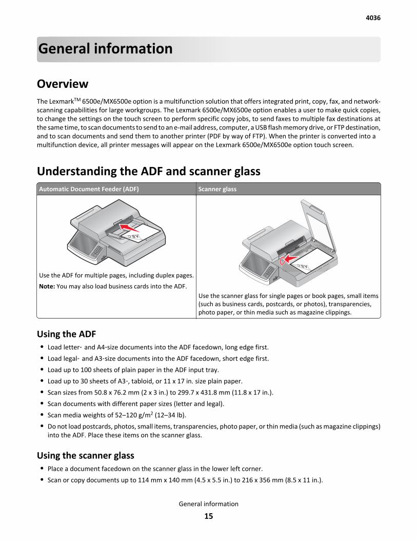
Understanding the ADF and scanner glassAutomatic Document Feeder (ADF) Scanner glass
Use the ADF for multiple pages, including duplex pages.
Note: You may also load business cards into the ADF.Use the scanner glass for single pages or book pages, small items(such as business cards, postcards, or photos), transparencies,photo paper, or thin media such as magazine clippings.
Using the ADF• Load letter‑ and A4‑size documents into the ADF facedown, long edge first.
• Load legal‑ and A3‑size documents into the ADF facedown, short edge first.
• Load up to 100 sheets of plain paper in the ADF input tray.
• Load up to 30 sheets of A3‑, tabloid, or 11 x 17 in. size plain paper.
• Scan sizes from 50.8 x 76.2 mm (2 x 3 in.) to 299.7 x 431.8 mm (11.8 x 17 in.).
• Scan documents with different paper sizes (letter and legal).
• Scan media weights of 52–120 g/m2 (12–34 lb).
• Do not load postcards, photos, small items, transparencies, photo paper, or thin media (such as magazine clippings)into the ADF. Place these items on the scanner glass.
Using the scanner glass• Place a document facedown on the scanner glass in the lower left corner.
• Scan or copy documents up to 114 mm x 140 mm (4.5 x 5.5 in.) to 216 x 356 mm (8.5 x 11 in.).
4036
General information
15

• Copy books with the book spine on the lower right corner of the scanner glass.
Tools required for serviceFlat-head screwdrivers, various sizes#1 Phillips screwdriver, magnetic#2 Phillips screwdriver, magnetic#2 Phillips screwdriver, magnetic short-bladeTorx screwdriversNeedle‑nose pliersDiagonal side cuttersSpring hookFeeler gaugesAnalog or digital multimeterFlashlight (optional)
4036
General information
16
Diagnostic information• “Power-On Self Test (POST) sequence” on page 18
• “Symptom tables” on page 18
• “Error codes and messages” on page 18
• “Paper jam error codes” on page 19
• “Frequent paper jam, multifeed, or skew” on page 20
• “False multifeed” on page 21
• “The power does not come on” on page 22
• “ADF cover open” on page 23
• “ADF paper present” on page 23
• “Image blank or distorted (ADF—back side of scanned page)” on page 24
• “Image blank or distorted (ADF—front side of scanned page)” on page 25
• “Strange sound generated (ADF)” on page 26
• “Flatbed cover open” on page 26
• “Image blank or distorted (flatbed)” on page 27
• “Strange sound generated (flatbed)” on page 28
• “Flatbed scanner home position” on page 28
• “Voided line in scanned image (ADF or flatbed)” on page 29
• “900.xx system software error” on page 29
CAUTION—SHOCK HAZARD: Remove the power cord from the electrical outlet before you connect ordisconnect any cable or electronic card or assembly for personal safety and to prevent damage to the printer.Disconnect any connections between the printer and PCs/peripherals.
This chapter describes two methods to solve the operational problems. The first relies on the scanner internaldiagnostics to report error codes. The second uses troubleshooting techniques to isolate the problem. In many cases,the internal error codes will help you to locate the source of the problem quickly. If no error codes are reported, or ifthe error codes do not locate the source of the problem, refer to the Symptom Tables.
• If you have an error message or user message, check the following:
– “Error codes and messages” on page 18
– “Paper jam error codes” on page 19
– “900.xx system software error” on page 29
• Does the POR stop? Check the “Power-On Self Test (POST) sequence” on page 18.
• Do you have a symptom, rather than an error message? Check the “Symptom tables” on page 18.
• Additional information can be found at the following locations:
– “Understanding the home screen” on page 35
– “Accessing the service menus” on page 41
Note: There may be scanner error messages that are not contained in this service manual. Call your next level ofsupport for assistance.
4036
Diagnostic information
17
Power-On Self Test (POST) sequenceWhen you turn the printer and scanner on, it performs a Power-On Self Test. Check for correct POST functioning byobserving the following:
1 The printer LED (green light) turns on.
2 The control panel turns on.
3 The control panel displays counting the memory.
4 The control panel displays a progression bar with the Lexmark splash logo.
5 You can hear the scanner doing a scanner calibration.
6 You can hear the printer starting up. It takes the printer longer to start up from a cold start rather than from a warmstart.
Symptom tablesThe tables in this section provide detailed troubleshooting information.
Frequent paper jam, multifeed, or skew See “Frequent paper jam, multifeed, or skew” on page 20.
False multifeed See “False multifeed” on page 21.
The power does not come on, or communication lost See “The power does not come on” on page 22.
Voided line in scanned image (ADF or flatbed) See “Voided line in scanned image (ADF or flatbed)” on page 29.
Image blank or distorted (flatbed) See “Image blank or distorted (flatbed)” on page 27.
Image blank or distorted (ADF—front side of scannedpage)
See “Image blank or distorted (ADF—front side of scanned page)”on page 25.
Image blank or distorted (ADF—back side of scannedpage)
See “Image blank or distorted (ADF—back side of scanned page)”on page 24.
Strange sound generated (ADF) See “Strange sound generated (ADF)” on page 26.
Strange sound generated (flatbed) See “Strange sound generated (flatbed)” on page 28.
Error codes and messagesNote: For information on error codes 910-999, refer to the printer’s service manual.
Error code Description Action
840.01 The scanner has been manuallydisabled.
Enter the configuration menu to re-enable thescanner.
840.02 The scanner has automaticallybeen disabled by the controller.
Enter the configuration menu to re-enable thescanner.
4036
Diagnostic information
18
Error code Description Action
841.XX The scanner image ASIC has failed. 1 Check all connections on the scanner engineboard.
2 Replace the scanner engine board assemblyif problem remains. See “Engine boardremoval” on page 120.
3 Replace the controller board. See “Controllerboard removal” on page 109.
842.XX The controller board has lostcommunication with the scannerengine board.
1 Check all connections on the scanner engineboard.
2 Replace the scanner engine board assemblyif problem remains. See “Engine boardremoval” on page 120.
3 Replace the controller board. See “Controllerboard removal” on page 109.
843.XX The scanner carriage home positiondetection failed.
1 Turn the machine off/on.
2 See the home position service check.
845.02 Lower scanner module cable hasfailed.
Replace the lower scanner module cable.
845.03 Upper scanner module cable hasfailed.
Replace the upper scanner module cable.
900.00-900.99
(except for 900.05)
An unrecoverable controller boardsoftware error occurred while anunknown process was running.
See “900.xx system software error” on page 29.
955.XX The Code ROM or NAND flash failedthe Cyclic Redundancy Check (CRC),or the NAND experienced anuncorrectable multibit failure.
Replace the controller board. See “Controllerboard removal” on page 109.
Paper jam error codesNote: For information on error codes 200-279, refer to the printer’s service manual.
Error code Description Action
280.06 Paper is missing from the ADF inputtray when the scanner expected tosee it.
See “ADF paper present” on page 23.
282.05 Paper reached the media sensorbut is late leaving or does not clearit within the specified time.
See “Frequent paper jam, multifeed, or skew” onpage 20.
283.01 Paper remains on the media sensorduring the warm-up sequence or atPOR.
See “Frequent paper jam, multifeed, or skew” onpage 20.
283.03 Paper does not reach or is latearriving at the media sensor withinthe specified time.
See “Frequent paper jam, multifeed, or skew” onpage 20.
4036
Diagnostic information
19
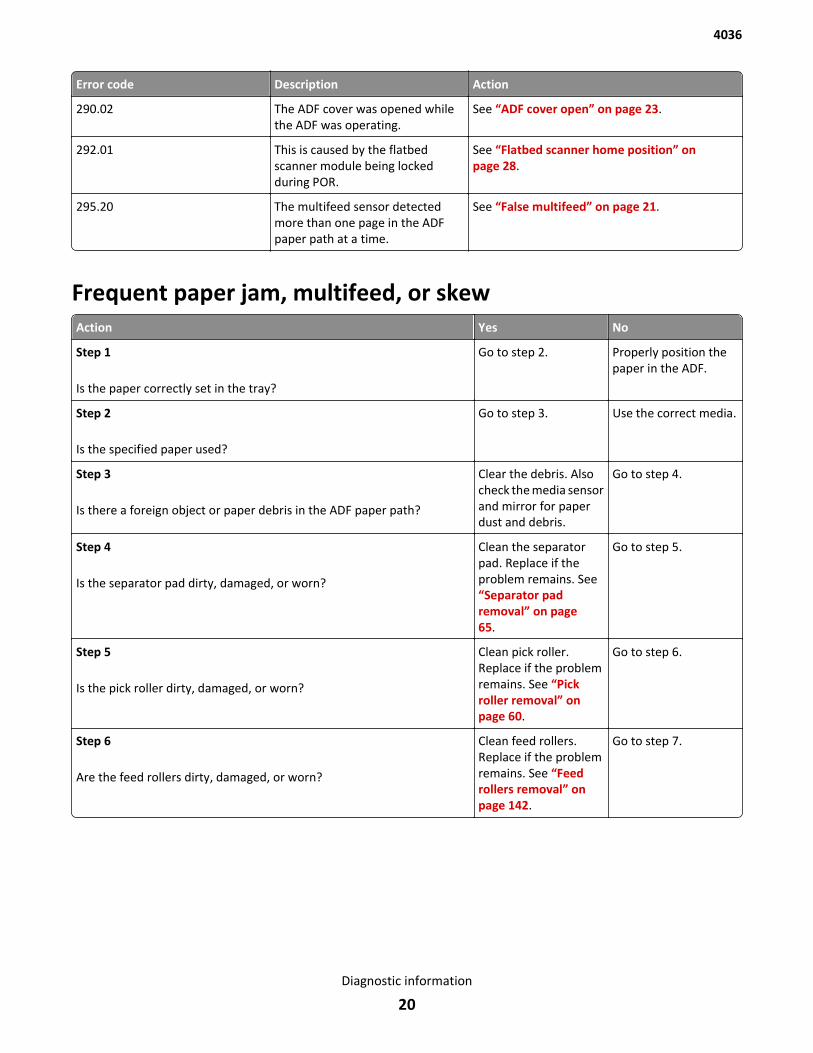
Error code Description Action
290.02 The ADF cover was opened whilethe ADF was operating.
See “ADF cover open” on page 23.
292.01 This is caused by the flatbedscanner module being lockedduring POR.
See “Flatbed scanner home position” onpage 28.
295.20 The multifeed sensor detectedmore than one page in the ADFpaper path at a time.
See “False multifeed” on page 21.
Frequent paper jam, multifeed, or skewAction Yes No
Step 1
Is the paper correctly set in the tray?
Go to step 2. Properly position thepaper in the ADF.
Step 2
Is the specified paper used?
Go to step 3. Use the correct media.
Step 3
Is there a foreign object or paper debris in the ADF paper path?
Clear the debris. Alsocheck the media sensorand mirror for paperdust and debris.
Go to step 4.
Step 4
Is the separator pad dirty, damaged, or worn?
Clean the separatorpad. Replace if theproblem remains. See“Separator padremoval” on page 65.
Go to step 5.
Step 5
Is the pick roller dirty, damaged, or worn?
Clean pick roller.Replace if the problemremains. See “Pickroller removal” onpage 60.
Go to step 6.
Step 6
Are the feed rollers dirty, damaged, or worn?
Clean feed rollers.Replace if the problemremains. See “Feedrollers removal” onpage 142.
Go to step 7.
4036
Diagnostic information
20
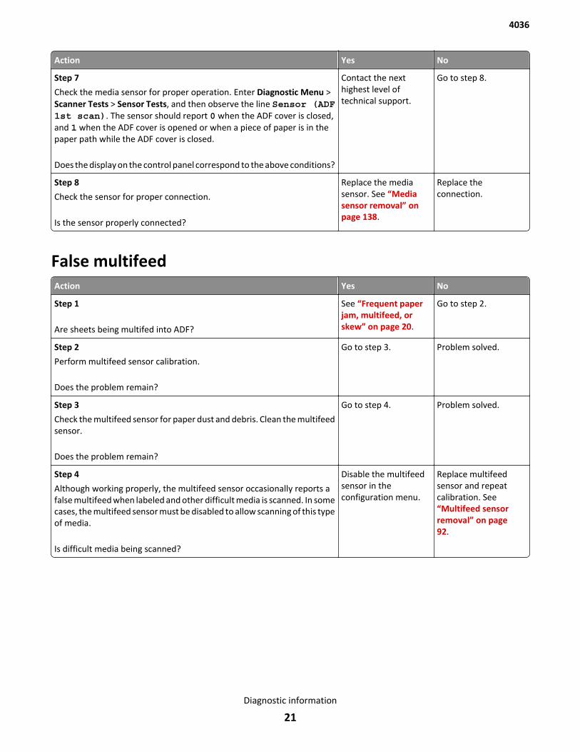
Action Yes No
Step 7
Check the media sensor for proper operation. Enter Diagnostic Menu >Scanner Tests > Sensor Tests, and then observe the line Sensor (ADF1st scan). The sensor should report 0 when the ADF cover is closed,and 1 when the ADF cover is opened or when a piece of paper is in thepaper path while the ADF cover is closed.
Does the display on the control panel correspond to the above conditions?
Contact the nexthighest level oftechnical support.
Go to step 8.
Step 8
Check the sensor for proper connection.
Is the sensor properly connected?
Replace the mediasensor. See “Mediasensor removal” onpage 138.
Replace theconnection.
False multifeedAction Yes No
Step 1
Are sheets being multifed into ADF?
See “Frequent paperjam, multifeed, orskew” on page 20.
Go to step 2.
Step 2
Perform multifeed sensor calibration.
Does the problem remain?
Go to step 3. Problem solved.
Step 3
Check the multifeed sensor for paper dust and debris. Clean the multifeedsensor.
Does the problem remain?
Go to step 4. Problem solved.
Step 4
Although working properly, the multifeed sensor occasionally reports afalse multifeed when labeled and other difficult media is scanned. In somecases, the multifeed sensor must be disabled to allow scanning of this typeof media.
Is difficult media being scanned?
Disable the multifeedsensor in theconfiguration menu.
Replace multifeedsensor and repeatcalibration. See“Multifeed sensorremoval” on page 92.
4036
Diagnostic information
21
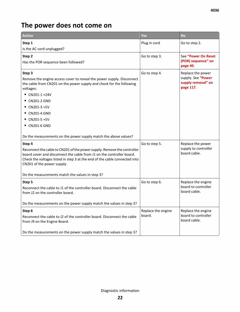
The power does not come onAction Yes No
Step 1
Is the AC cord unplugged?
Plug in cord Go to step 2.
Step 2
Has the POR sequence been followed?
Go to step 3. See “Power On Reset(POR) sequence” onpage 40.
Step 3
Remove the engine access cover to reveal the power supply. Disconnectthe cable from CN201 on the power supply and check for the followingvoltages:
• CN201-1 +24V
• CN201-2 GND
• CN201-3 +5V
• CN201-4 GND
• CN201-5 +5V
• CN201-6 GND
Do the measurements on the power supply match the above values?
Go to step 4. Replace the powersupply. See “Powersupply removal” onpage 117.
Step 4
Reconnect the cable to CN201 of the power supply. Remove the controllerboard cover and disconnect the cable from J1 on the controller board.Check the voltages listed in step 3 at the end of the cable connected intoCN201 of the power supply.
Do the measurements match the values in step 3?
Go to step 5. Replace the powersupply to controllerboard cable.
Step 5
Reconnect the cable to J1 of the controller board. Disconnect the cablefrom J2 on the controller board.
Do the measurements on the power supply match the values in step 3?
Go to step 6. Replace the engineboard to controllerboard cable.
Step 6
Reconnect the cable to J2 of the controller board. Disconnect the cablefrom J9 on the Engine Board.
Do the measurements on the power supply match the values in step 3?
Replace the engineboard.
Replace the engineboard to controllerboard cable.
4036
Diagnostic information
22
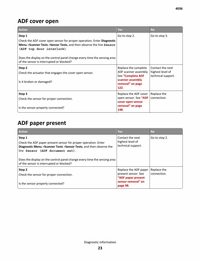
ADF cover openAction Yes No
Step 1
Check the ADF cover open sensor for proper operation. Enter DiagnosticMenu >Scanner Tests >Sensor Tests, and then observe the line Sensor(ADF top door interlock).
Does the display on the control panel change every time the sensing areaof the sensor is interrupted or blocked?
Go to step 2. Go to step 3.
Step 2
Check the actuator that engages the cover open sensor.
Is it broken or damaged?
Replace the completeADF scanner assembly.See “Complete ADFscanner assemblyremoval” on page 122.
Contact the nexthighest level oftechnical support.
Step 3
Check the sensor for proper connection.
Is the sensor properly connected?
Replace the ADF coveropen sensor. See “ADFcover open sensorremoval” on page 148.
Replace theconnection.
ADF paper presentAction Yes No
Step 1
Check the ADF paper present sensor for proper operation. EnterDiagnostic Menu >Scanner Tests >Sensor Tests, and then observe theline Sensor (ADF document set).
Does the display on the control panel change every time the sensing areaof the sensor is interrupted or blocked?
Contact the nexthighest level oftechnical support.
Go to step 2.
Step 2
Check the sensor for proper connection.
Is the sensor properly connected?
Replace the ADF paperpresent sensor. See“ADF paper presentsensor removal” onpage 98.
Replace theconnection.
4036
Diagnostic information
23

Image blank or distorted (ADF—back side of scanned page)Action Yes No
Step 1
Is the separator pad dirty, damaged, or worn?
Clean separator pad.Replace if problemremains. See“Separator padremoval” on page 65.
Go to step 2.
Step 2
Is the pick roller dirty, damaged, or worn?
Clean pick roller.Replace if problemremains. See “Pickroller removal” onpage 60.
Go to step 3.
Step 3
Are the feed rollers dirty, damaged, or worn?
Clean feed rollers.Replace if problemremains. See “Feedrollers removal” onpage 142.
Go to step 4.
Step 4
Check the cable connection between the upper ADF scanner module andJ6 on the controller board.
Is the cable properly seated and free from damage?
Go to step 5. Reconnect or replacethe cable.
Step 5
Check the following voltages on J6 of the Controller Board:
• J6-1 GND
• J6-4 GND
• J6-7 GND
• J6-10 GND
• J6-13 GND
• J6-16 GND
• J6-18 GND
• J6-26 GND
• J6-27 +24V
• J6-28 +24V
• J6-30 GND
• J6-31 GND
• J6-32 GND
Do the measurements on the controller board match the above values?
Replace the upper ADFscanner module. See“Upper ADF scannermodule removal” onpage 89.
Replace the controllerboard. See “Controllerboard removal” onpage 109.
4036
Diagnostic information
24
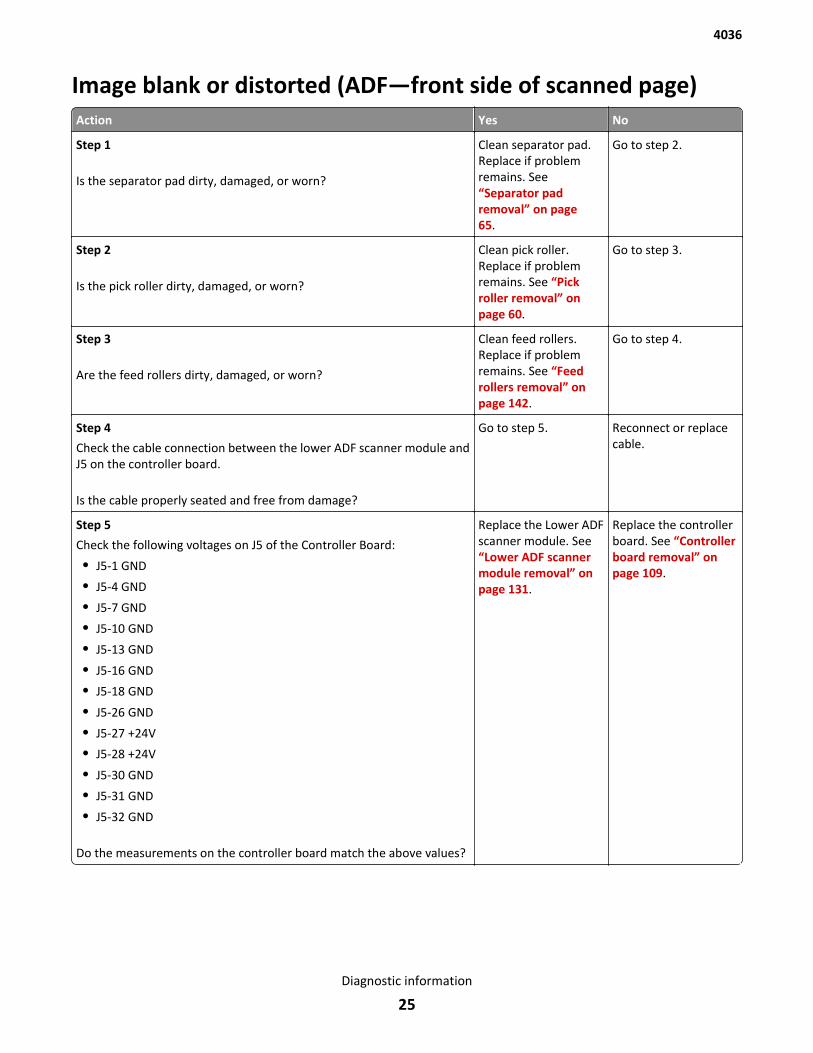
Image blank or distorted (ADF—front side of scanned page)Action Yes No
Step 1
Is the separator pad dirty, damaged, or worn?
Clean separator pad.Replace if problemremains. See“Separator padremoval” on page 65.
Go to step 2.
Step 2
Is the pick roller dirty, damaged, or worn?
Clean pick roller.Replace if problemremains. See “Pickroller removal” onpage 60.
Go to step 3.
Step 3
Are the feed rollers dirty, damaged, or worn?
Clean feed rollers.Replace if problemremains. See “Feedrollers removal” onpage 142.
Go to step 4.
Step 4
Check the cable connection between the lower ADF scanner module andJ5 on the controller board.
Is the cable properly seated and free from damage?
Go to step 5. Reconnect or replacecable.
Step 5
Check the following voltages on J5 of the Controller Board:
• J5-1 GND
• J5-4 GND
• J5-7 GND
• J5-10 GND
• J5-13 GND
• J5-16 GND
• J5-18 GND
• J5-26 GND
• J5-27 +24V
• J5-28 +24V
• J5-30 GND
• J5-31 GND
• J5-32 GND
Do the measurements on the controller board match the above values?
Replace the Lower ADFscanner module. See“Lower ADF scannermodule removal” onpage 131.
Replace the controllerboard. See “Controllerboard removal” onpage 109.
4036
Diagnostic information
25
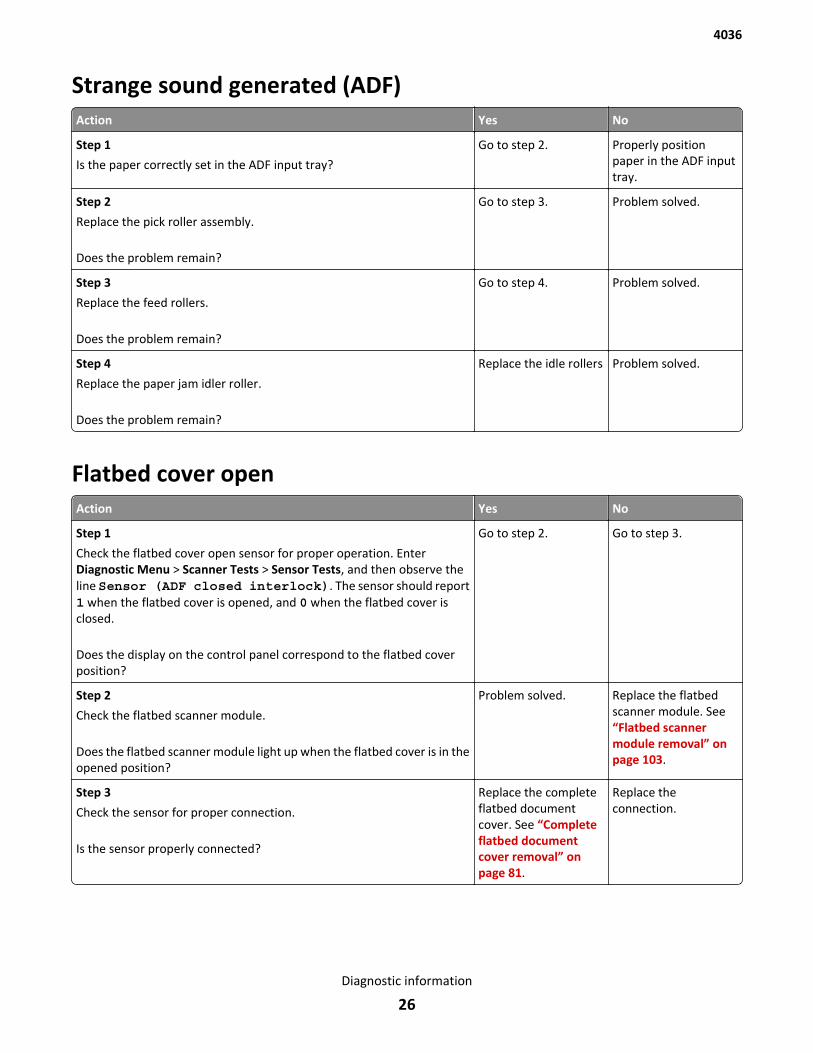
Strange sound generated (ADF)Action Yes No
Step 1
Is the paper correctly set in the ADF input tray?
Go to step 2. Properly positionpaper in the ADF inputtray.
Step 2
Replace the pick roller assembly.
Does the problem remain?
Go to step 3. Problem solved.
Step 3
Replace the feed rollers.
Does the problem remain?
Go to step 4. Problem solved.
Step 4
Replace the paper jam idler roller.
Does the problem remain?
Replace the idle rollers Problem solved.
Flatbed cover openAction Yes No
Step 1
Check the flatbed cover open sensor for proper operation. EnterDiagnostic Menu > Scanner Tests > Sensor Tests, and then observe theline Sensor (ADF closed interlock). The sensor should report1 when the flatbed cover is opened, and 0 when the flatbed cover isclosed.
Does the display on the control panel correspond to the flatbed coverposition?
Go to step 2. Go to step 3.
Step 2
Check the flatbed scanner module.
Does the flatbed scanner module light up when the flatbed cover is in theopened position?
Problem solved. Replace the flatbedscanner module. See“Flatbed scannermodule removal” onpage 103.
Step 3
Check the sensor for proper connection.
Is the sensor properly connected?
Replace the completeflatbed documentcover. See “Completeflatbed documentcover removal” onpage 81.
Replace theconnection.
4036
Diagnostic information
26
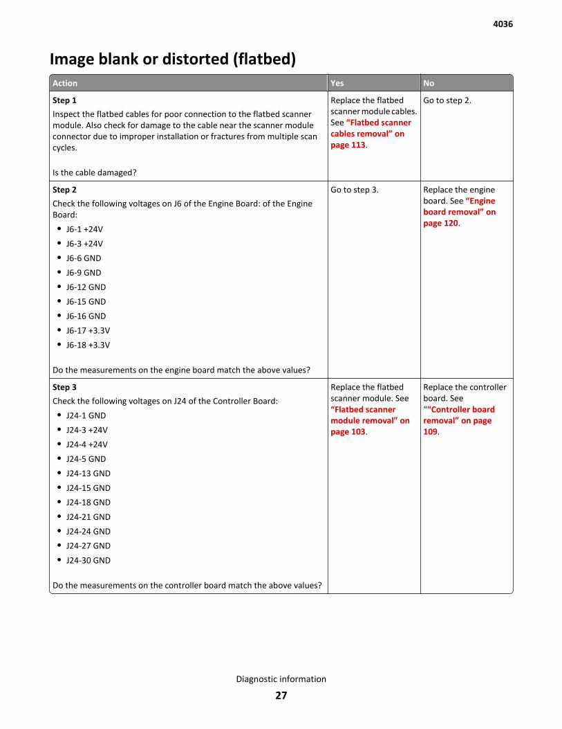
Image blank or distorted (flatbed)Action Yes No
Step 1
Inspect the flatbed cables for poor connection to the flatbed scannermodule. Also check for damage to the cable near the scanner moduleconnector due to improper installation or fractures from multiple scancycles.
Is the cable damaged?
Replace the flatbedscanner module cables.See “Flatbed scannercables removal” onpage 113.
Go to step 2.
Step 2
Check the following voltages on J6 of the Engine Board: of the EngineBoard:
• J6-1 +24V
• J6-3 +24V
• J6-6 GND
• J6-9 GND
• J6-12 GND
• J6-15 GND
• J6-16 GND
• J6-17 +3.3V
• J6-18 +3.3V
Do the measurements on the engine board match the above values?
Go to step 3. Replace the engineboard. See “Engineboard removal” onpage 120.
Step 3
Check the following voltages on J24 of the Controller Board:
• J24-1 GND
• J24-3 +24V
• J24-4 +24V
• J24-5 GND
• J24-13 GND
• J24-15 GND
• J24-18 GND
• J24-21 GND
• J24-24 GND
• J24-27 GND
• J24-30 GND
Do the measurements on the controller board match the above values?
Replace the flatbedscanner module. See“Flatbed scannermodule removal” onpage 103.
Replace the controllerboard. See““Controller boardremoval” on page 109.
4036
Diagnostic information
27
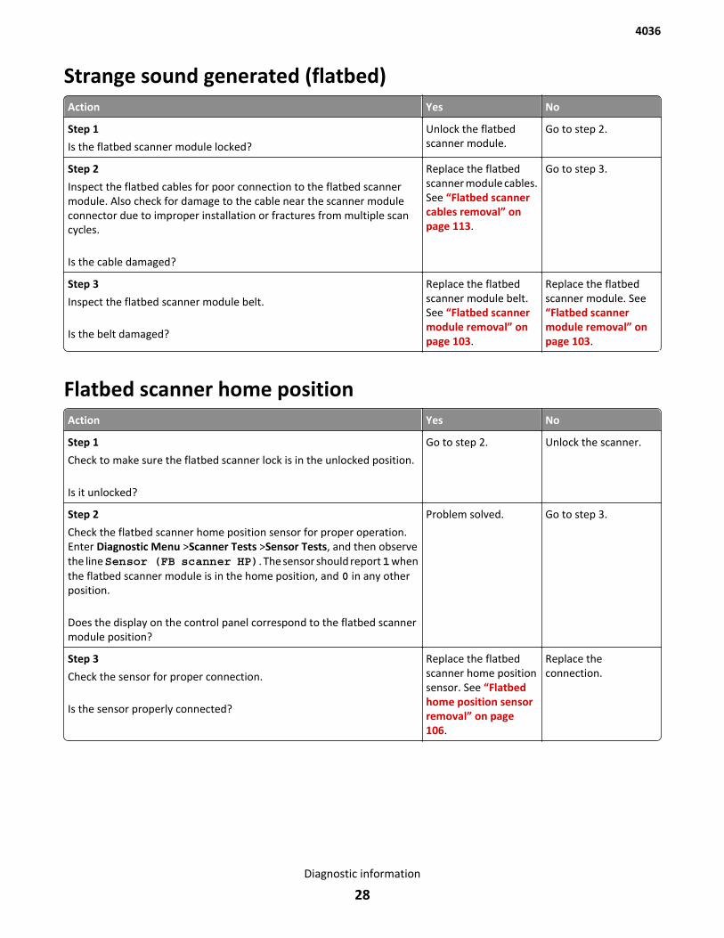
Strange sound generated (flatbed)Action Yes No
Step 1
Is the flatbed scanner module locked?
Unlock the flatbedscanner module.
Go to step 2.
Step 2
Inspect the flatbed cables for poor connection to the flatbed scannermodule. Also check for damage to the cable near the scanner moduleconnector due to improper installation or fractures from multiple scancycles.
Is the cable damaged?
Replace the flatbedscanner module cables.See “Flatbed scannercables removal” onpage 113.
Go to step 3.
Step 3
Inspect the flatbed scanner module belt.
Is the belt damaged?
Replace the flatbedscanner module belt.See “Flatbed scannermodule removal” onpage 103.
Replace the flatbedscanner module. See“Flatbed scannermodule removal” onpage 103.
Flatbed scanner home positionAction Yes No
Step 1
Check to make sure the flatbed scanner lock is in the unlocked position.
Is it unlocked?
Go to step 2. Unlock the scanner.
Step 2
Check the flatbed scanner home position sensor for proper operation.Enter Diagnostic Menu >Scanner Tests >Sensor Tests, and then observethe line Sensor (FB scanner HP). The sensor should report 1 whenthe flatbed scanner module is in the home position, and 0 in any otherposition.
Does the display on the control panel correspond to the flatbed scannermodule position?
Problem solved. Go to step 3.
Step 3
Check the sensor for proper connection.
Is the sensor properly connected?
Replace the flatbedscanner home positionsensor. See “Flatbedhome position sensorremoval” on page 106.
Replace theconnection.
4036
Diagnostic information
28
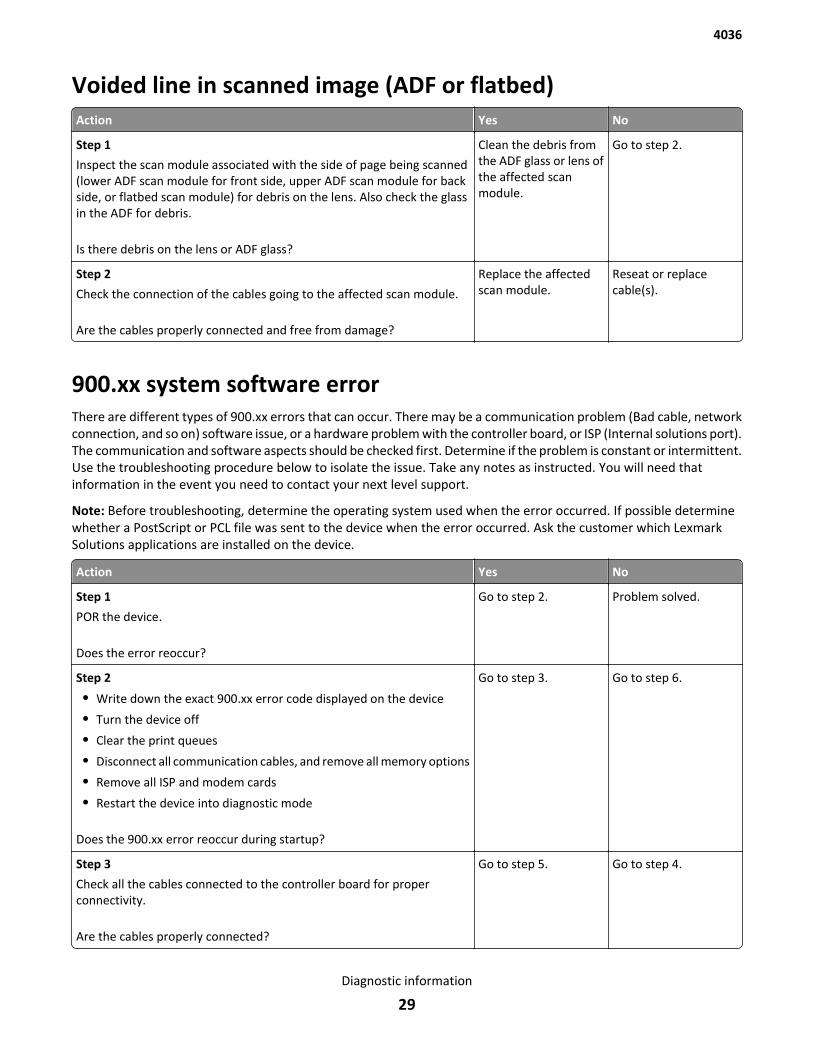
Voided line in scanned image (ADF or flatbed)Action Yes No
Step 1
Inspect the scan module associated with the side of page being scanned(lower ADF scan module for front side, upper ADF scan module for backside, or flatbed scan module) for debris on the lens. Also check the glassin the ADF for debris.
Is there debris on the lens or ADF glass?
Clean the debris fromthe ADF glass or lens ofthe affected scanmodule.
Go to step 2.
Step 2
Check the connection of the cables going to the affected scan module.
Are the cables properly connected and free from damage?
Replace the affectedscan module.
Reseat or replacecable(s).
900.xx system software errorThere are different types of 900.xx errors that can occur. There may be a communication problem (Bad cable, networkconnection, and so on) software issue, or a hardware problem with the controller board, or ISP (Internal solutions port).The communication and software aspects should be checked first. Determine if the problem is constant or intermittent.Use the troubleshooting procedure below to isolate the issue. Take any notes as instructed. You will need thatinformation in the event you need to contact your next level support.
Note: Before troubleshooting, determine the operating system used when the error occurred. If possible determinewhether a PostScript or PCL file was sent to the device when the error occurred. Ask the customer which LexmarkSolutions applications are installed on the device.
Action Yes No
Step 1
POR the device.
Does the error reoccur?
Go to step 2. Problem solved.
Step 2
• Write down the exact 900.xx error code displayed on the device
• Turn the device off
• Clear the print queues
• Disconnect all communication cables, and remove all memory options
• Remove all ISP and modem cards
• Restart the device into diagnostic mode
Does the 900.xx error reoccur during startup?
Go to step 3. Go to step 6.
Step 3
Check all the cables connected to the controller board for properconnectivity.
Are the cables properly connected?
Go to step 5. Go to step 4.
4036
Diagnostic information
29
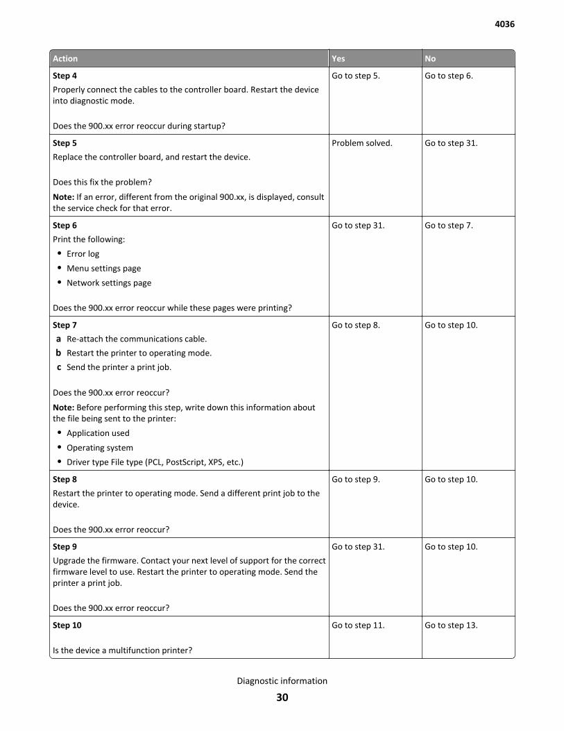
Action Yes No
Step 4
Properly connect the cables to the controller board. Restart the deviceinto diagnostic mode.
Does the 900.xx error reoccur during startup?
Go to step 5. Go to step 6.
Step 5
Replace the controller board, and restart the device.
Does this fix the problem?
Note: If an error, different from the original 900.xx, is displayed, consultthe service check for that error.
Problem solved. Go to step 31.
Step 6
Print the following:
• Error log
• Menu settings page
• Network settings page
Does the 900.xx error reoccur while these pages were printing?
Go to step 31. Go to step 7.
Step 7
a Re-attach the communications cable.
b Restart the printer to operating mode.
c Send the printer a print job.
Does the 900.xx error reoccur?
Note: Before performing this step, write down this information aboutthe file being sent to the printer:
• Application used
• Operating system
• Driver type File type (PCL, PostScript, XPS, etc.)
Go to step 8. Go to step 10.
Step 8
Restart the printer to operating mode. Send a different print job to thedevice.
Does the 900.xx error reoccur?
Go to step 9. Go to step 10.
Step 9
Upgrade the firmware. Contact your next level of support for the correctfirmware level to use. Restart the printer to operating mode. Send theprinter a print job.
Does the 900.xx error reoccur?
Go to step 31. Go to step 10.
Step 10
Is the device a multifunction printer?
Go to step 11. Go to step 13.
4036
Diagnostic information
30
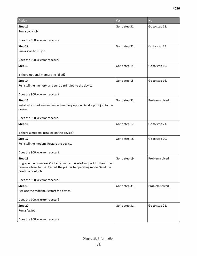
Action Yes No
Step 11
Run a copy job.
Does the 900.xx error reoccur?
Go to step 31. Go to step 12.
Step 12
Run a scan to PC job.
Does the 900.xx error reoccur?
Go to step 31. Go to step 13.
Step 13
Is there optional memory installed?
Go to step 14. Go to step 16.
Step 14
Reinstall the memory, and send a print job to the device.
Does the 900.xx error reoccur?
Go to step 15. Go to step 16.
Step 15
Install a Lexmark recommended memory option. Send a print job to thedevice.
Does the 900.xx error reoccur?
Go to step 31. Problem solved.
Step 16
Is there a modem installed on the device?
Go to step 17. Go to step 21.
Step 17
Reinstall the modem. Restart the device.
Does the 900.xx error reoccur?
Go to step 18. Go to step 20.
Step 18
Upgrade the firmware. Contact your next level of support for the correctfirmware level to use. Restart the printer to operating mode. Send theprinter a print job.
Does the 900.xx error reoccur?
Go to step 19. Problem solved.
Step 19
Replace the modem. Restart the device.
Does the 900.xx error reoccur?
Go to step 31. Problem solved.
Step 20
Run a fax job.
Does the 900.xx error reoccur?
Go to step 31. Go to step 21.
4036
Diagnostic information
31
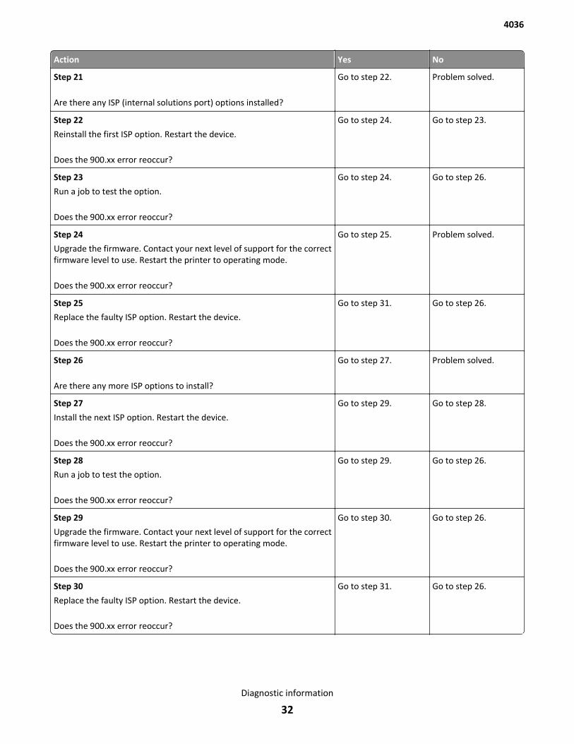
Action Yes No
Step 21
Are there any ISP (internal solutions port) options installed?
Go to step 22. Problem solved.
Step 22
Reinstall the first ISP option. Restart the device.
Does the 900.xx error reoccur?
Go to step 24. Go to step 23.
Step 23
Run a job to test the option.
Does the 900.xx error reoccur?
Go to step 24. Go to step 26.
Step 24
Upgrade the firmware. Contact your next level of support for the correctfirmware level to use. Restart the printer to operating mode.
Does the 900.xx error reoccur?
Go to step 25. Problem solved.
Step 25
Replace the faulty ISP option. Restart the device.
Does the 900.xx error reoccur?
Go to step 31. Go to step 26.
Step 26
Are there any more ISP options to install?
Go to step 27. Problem solved.
Step 27
Install the next ISP option. Restart the device.
Does the 900.xx error reoccur?
Go to step 29. Go to step 28.
Step 28
Run a job to test the option.
Does the 900.xx error reoccur?
Go to step 29. Go to step 26.
Step 29
Upgrade the firmware. Contact your next level of support for the correctfirmware level to use. Restart the printer to operating mode.
Does the 900.xx error reoccur?
Go to step 30. Go to step 26.
Step 30
Replace the faulty ISP option. Restart the device.
Does the 900.xx error reoccur?
Go to step 31. Go to step 26.
4036
Diagnostic information
32
Action Yes No
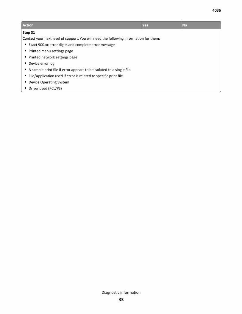
Step 31
Contact your next level of support. You will need the following information for them:
• Exact 900.xx error digits and complete error message
• Printed menu settings page
• Printed network settings page
• Device error log
• A sample print file if error appears to be isolated to a single file
• File/Application used if error is related to specific print file
• Device Operating System
• Driver used (PCL/PS)
4036
Diagnostic information
33

4036
34
Service menus
Understanding the control panel and menus
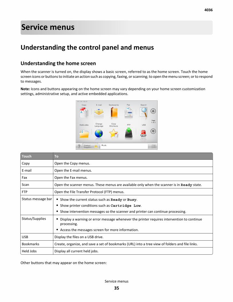
Understanding the home screenWhen the scanner is turned on, the display shows a basic screen, referred to as the home screen. Touch the homescreen icons or buttons to initiate an action such as copying, faxing, or scanning; to open the menu screen; or to respondto messages.
Note: Icons and buttons appearing on the home screen may vary depending on your home screen customizationsettings, administrative setup, and active embedded applications.
Touch To
Copy Open the Copy menus.
E-mail Open the E-mail menus.
Fax Open the Fax menus.
Scan Open the scanner menus. These menus are available only when the scanner is in Ready state.
FTP Open the File Transfer Protocol (FTP) menus.
Status message bar • Show the current status such as Ready or Busy.
• Show printer conditions such as Cartridge Low.
• Show intervention messages so the scanner and printer can continue processing.
Status/Supplies • Display a warning or error message whenever the printer requires intervention to continueprocessing.
• Access the messages screen for more information.
USB Display the files on a USB drive.
Bookmarks Create, organize, and save a set of bookmarks (URL) into a tree view of folders and file links.
Held Jobs Display all current held jobs.
Other buttons that may appear on the home screen:
4036
Service menus
35
Touch this To
Release Held Fax Access the list of held faxes.
This button appears only when there are scheduled held faxes.
Lock Device Enter the correct password to lock the scanner control panel.
This button appears when the scanner is unlocked and password hasbeen set.
Unlock Device Enter the correct password to unlock the scanner control panel.
This button appears when the scanner is locked.
Cancel Jobs Open the Cancel Jobs screen. The Cancel Jobs screen shows threeheadings: Print, Fax, and Network.
The following options are available under the Print, Fax, and Networkheadings:
• Print job
• Copy job
• Fax profile
• FTP
• E-mail send
Each heading has a list of jobs shown in a column under it which canshow only three jobs per screen. If more than three jobs exist in acolumn, then an arrow appears enabling you to scroll through the jobs.
Change Language Launch the Change Language pop‑up window that allows you to changethe primary language of the scanner.
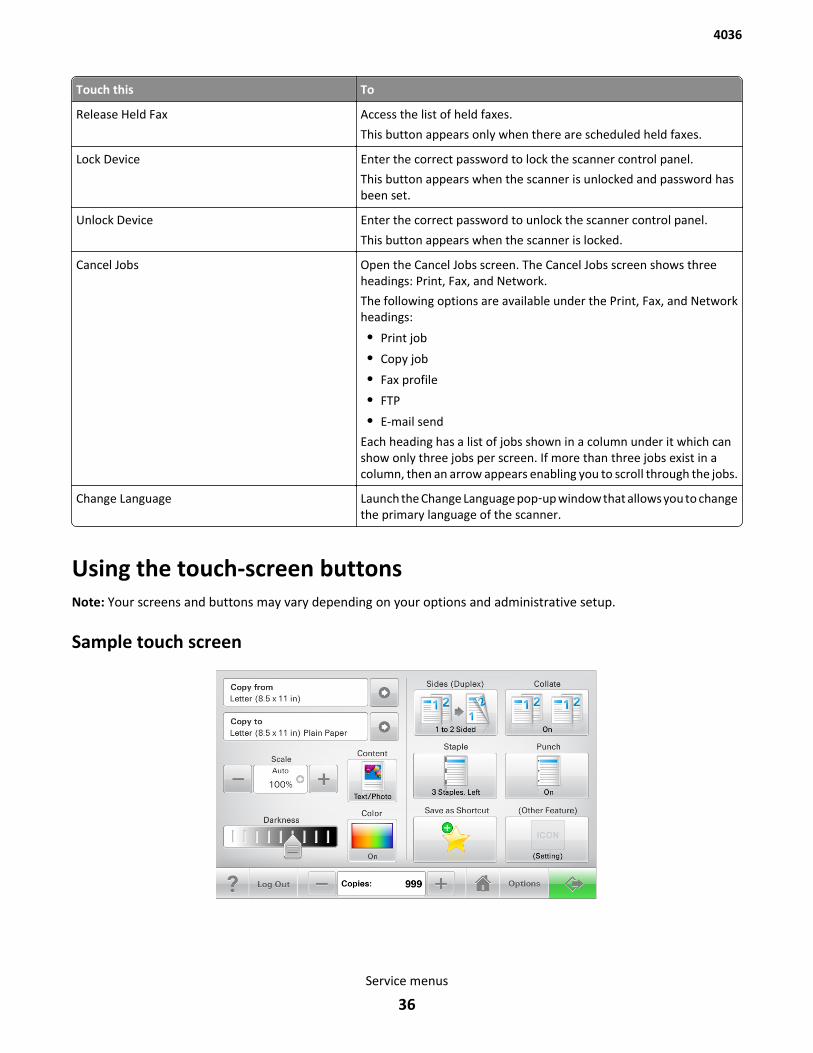
Using the touch-screen buttonsNote: Your screens and buttons may vary depending on your options and administrative setup.
Sample touch screen
4036
Service menus
36
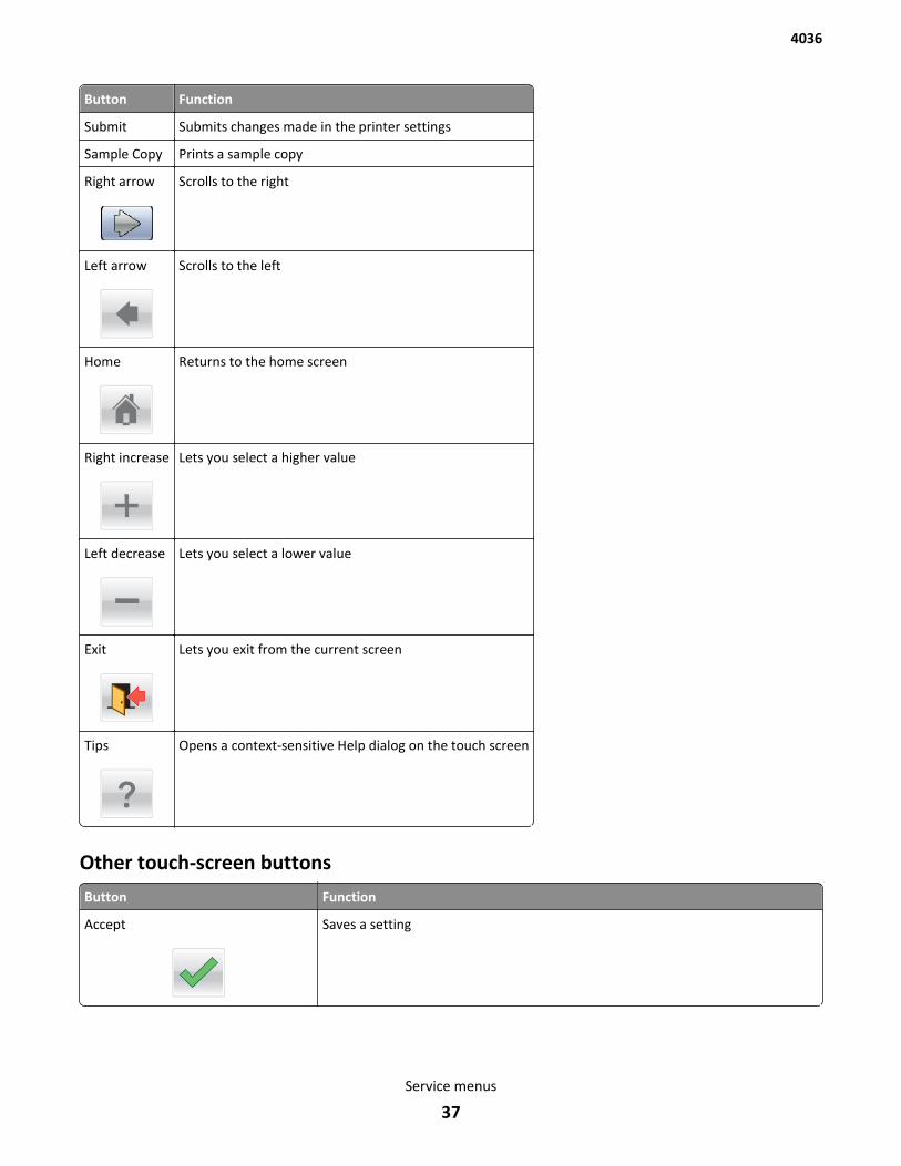
Button Function
Submit Submits changes made in the printer settings
Sample Copy Prints a sample copy
Right arrow Scrolls to the right
Left arrow Scrolls to the left
Home Returns to the home screen
Right increase Lets you select a higher value
Left decrease Lets you select a lower value
Exit Lets you exit from the current screen
Tips Opens a context-sensitive Help dialog on the touch screen
Other touch-screen buttons
Button Function
Accept Saves a setting
4036
Service menus
37
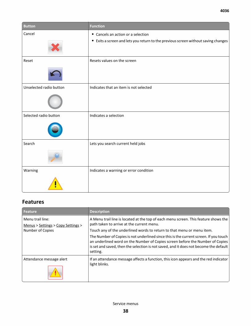
Button Function
Cancel • Cancels an action or a selection
• Exits a screen and lets you return to the previous screen without saving changes
Reset Resets values on the screen
Unselected radio button Indicates that an item is not selected
Selected radio button Indicates a selection
Search Lets you search current held jobs
Warning Indicates a warning or error condition
Features
Feature Description
Menu trail line:
Menus > Settings > Copy Settings >Number of Copies
A Menu trail line is located at the top of each menu screen. This feature shows thepath taken to arrive at the current menu.
Touch any of the underlined words to return to that menu or menu item.
The Number of Copies is not underlined since this is the current screen. If you touchan underlined word on the Number of Copies screen before the Number of Copiesis set and saved, then the selection is not saved, and it does not become the defaultsetting.
Attendance message alert If an attendance message affects a function, this icon appears and the red indicatorlight blinks.
4036
Service menus
38
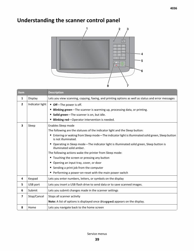
Understanding the scanner control panel
2ABC 3DEF
5JKL 6MNO4GHI
7PQRS 8TUV 9WXYZ
#0
1@!.
3
4
6
78
2
5
1
Item Description
1 Display Lets you view scanning, copying, faxing, and printing options as well as status and error messages
2 Indicator light • Off—The power is off.
• Blinking green—The scanner is warming up, processing data, or printing.
• Solid green—The scanner is on, but idle.
• Blinking red—Operator intervention is needed.
3 Sleep Enables Sleep mode
The following are the statuses of the indicator light and the Sleep button:
• Entering or waking from Sleep mode—The indicator light is illuminated solid green, Sleep buttonis not illuminated.
• Operating in Sleep mode—The indicator light is illuminated solid green, Sleep button isilluminated solid amber.
The following actions wake the printer from Sleep mode:
• Touching the screen or pressing any button
• Opening an input tray, cover, or door
• Sending a print job from the computer
• Performing a power‑on‑reset with the main power switch
4 Keypad Lets you enter numbers, letters, or symbols on the display
5 USB port Lets you insert a USB flash drive to send data or to save scanned images.
6 Submit Lets you submit changes made in the scanner settings
7 Stop/Cancel Stops all scanner activity
Note: A list of options is displayed once Stopped appears on the display.
8 Home Lets you navigate back to the home screen
4036
Service menus
39
Power On Reset (POR) sequenceThe POR sequence must be followed in order for the printer and scanner to properly power up and establishcommunications with each other and the network. Follow one of the two POR sequences:
Printer and scanner1 With both the printer and scanner previously turned off, turn on the printer.
2 Press and hold button pattern for desired service menu, or no buttons for user mode.
3 Turn on the scanner within 20 seconds of turning on the printer.
4 Release the buttons when the splash screen appears.
Scanner onlyNote: The scanner only POR applies only to a printer/scanner that was already powered up prior to the POR. (This isuseful for a service technician who needs to power in and out of service menus).
1 Turn off the scanner.
2 Press and hold button pattern for desired service menu, or no buttons for the user mode.
3 Turn on the scanner within 20 seconds of turning off the scanner.
4 Release the buttons when the splash screen appears.
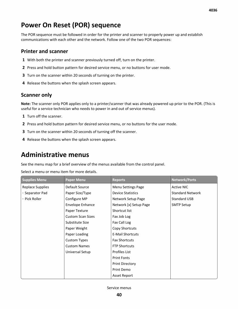
Administrative menusSee the menu map for a brief overview of the menus available from the control panel.
Select a menu or menu item for more details.
Supplies Menu Paper Menu Reports Network/Ports
Replace Supplies
‑ Separator Pad
‑ Pick Roller
Default Source
Paper Size/Type
Configure MP
Envelope Enhance
Paper Texture
Custom Scan Sizes
Substitute Size
Paper Weight
Paper Loading
Custom Types
Custom Names
Universal Setup
Menu Settings Page
Device Statistics
Network Setup Page
Network [x] Setup Page
Shortcut list
Fax Job Log
Fax Call Log
Copy Shortcuts
E-Mail Shortcuts
Fax Shortcuts
FTP Shortcuts
Profiles List
Print Fonts
Print Directory
Print Demo
Asset Report
Active NIC
Standard Network
Standard USB
SMTP Setup
4036
Service menus
40
Security Setting Manage Shortcuts Help Lock Scanner Head
Miscellaneous
Security Settings
Confidential Print
Disk Wiping
Security Audit Log
Set Date and Time
General Settings
Copy Settings
Fax Settings
E-Mail Settings
Flash Drive Menu
Print Settings
Image Menu
FTP Settings
Fax Shortcuts Security
E-mail Shortcuts
FTP Shortcuts
Copy Shortcuts
Profile Shortcuts
Print All Guides
Copy Guide
E-mail Guide
Fax Guide
FTP Guide
Print Defects Guide
Information Guide
Supplies Guide
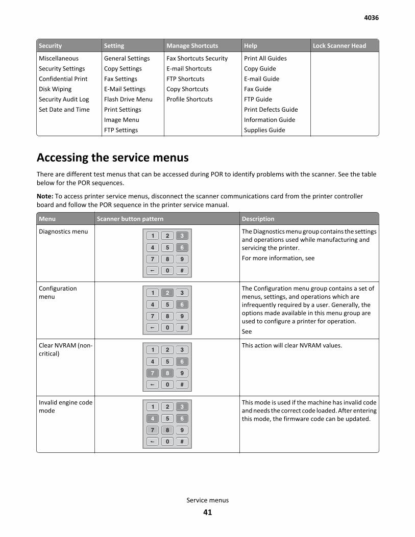
Accessing the service menusThere are different test menus that can be accessed during POR to identify problems with the scanner. See the tablebelow for the POR sequences.
Note: To access printer service menus, disconnect the scanner communications card from the printer controllerboard and follow the POR sequence in the printer service manual.
Menu Scanner button pattern Description
Diagnostics menu The Diagnostics menu group contains the settingsand operations used while manufacturing andservicing the printer.
For more information, see
Configurationmenu
The Configuration menu group contains a set ofmenus, settings, and operations which areinfrequently required by a user. Generally, theoptions made available in this menu group areused to configure a printer for operation.
See
Clear NVRAM (non-critical)
This action will clear NVRAM values.
Invalid engine codemode
This mode is used if the machine has invalid codeand needs the correct code loaded. After enteringthis mode, the firmware code can be updated.
4036
Service menus
41
Menu Scanner button pattern Description
Bypass firmwarecard
Submit button Holding this button during POR will cause thescanner to boot with code soldered on thecontroller board and bypass an installed firmwarecard.
SE menu At the scanner, perform the following steps:
1 From the Admin menu, navigate to the homescreen.
2 Press the button sequence: * * 4 1 1
3 The SE Menu appears.
This enables the SE menu.
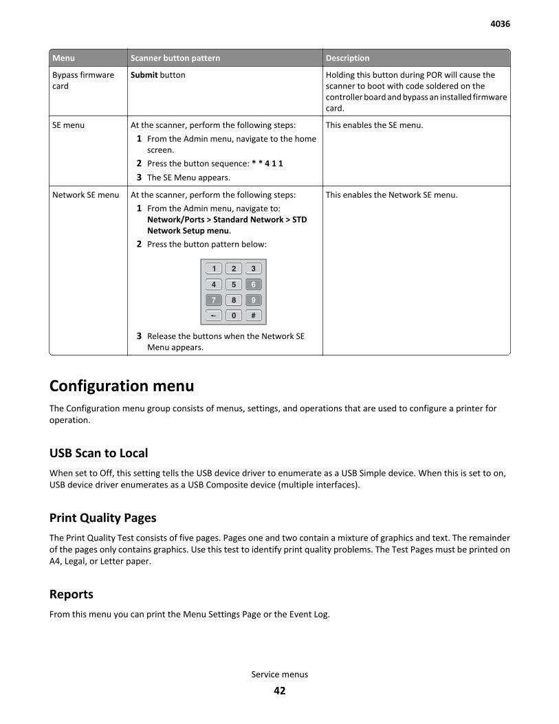
Network SE menu At the scanner, perform the following steps:
1 From the Admin menu, navigate to:Network/Ports > Standard Network > STDNetwork Setup menu.
2 Press the button pattern below:
3 Release the buttons when the Network SEMenu appears.
This enables the Network SE menu.
Configuration menuThe Configuration menu group consists of menus, settings, and operations that are used to configure a printer foroperation.
USB Scan to LocalWhen set to Off, this setting tells the USB device driver to enumerate as a USB Simple device. When this is set to on,USB device driver enumerates as a USB Composite device (multiple interfaces).
Print Quality PagesThe Print Quality Test consists of five pages. Pages one and two contain a mixture of graphics and text. The remainderof the pages only contains graphics. Use this test to identify print quality problems. The Test Pages must be printed onA4, Legal, or Letter paper.
ReportsFrom this menu you can print the Menu Settings Page or the Event Log.
4036
Service menus
42
SIZE SENSINGAutomatic size sensing can be disabled or enabled in this menu. Only paper sources that support Auto Size Sensing aredisplayed.
1 Select SIZE SENSING from the Configuration menu.
2 Select a tray. Only those trays with size sensing appear. Select Auto to turn size sensing on for that tray, or selectOff to disable size sensing.
3 Touch Back to exit.
Panel MenusDisabling Panel Menus prohibits users from modifying any setting or executing any operation available in the ReadyMenu group.
PPDS EmulationThis appears only if the PPDS interpreter is available.
Factory DefaultsThe customer can restore either the network settings or the base printer settings to their factory default values. WhenRestore Base is selected, non-critical base printer NVRAM settings are restored. When Restore STD Net is selected, allnetwork NVRAM settings are restored to their factory default settings. This option is available only on models with anintegrated network adapter. When Restore LES is selected, all non-standard applications are removed and all frameworkand standard application settings are reset to factory default settings.
Energy ConserveWhen Energy Conserve is on, the customer does not have access to disable the Sleep Mode function. When EnergyConserve is off, Disable appears as an additional menu item in the Sleep Mode menu. This setting only affects the valuesthat are displayed in the Sleep Mode menu.
Fax Low Power SupportThis menu has the following settings:
• Auto—The printer checks the Caller ID Pattern setting to determine if the fax chip should enter low power.
• Permit Sleep—The fax chip enters low power mode when needed, regardless of the Caller ID Patter setting.
• Disable Sleep—The fax chip never enters low power mode.
Min Copy MemoryThis menu lets you select the amount of memory dedicated to storing copy jobs. The values may be 25 MB, 35 MB, 50MB, 80 MB, and 100 MB. The default is 80 MB. Values will be displayed only if the amount of installed DRAM is at leasttwice the amount of the value. For example, at least 200 MB of installed DRAM is required to display the 100 MBselection.
4036
Service menus
43
NumPad Job AssistWhen this setting is set to On, a user can initiate scanner-related jobs, and enter values for a limited number of settingsrelated to those jobs, using the keypad.
Touch Back to exit without changing the setting.
Format Fax StorageThis setting enables you to format the non-volatile storage used for storing faxes.
Note: If an advanced password has been established, you must enter this password in order to change the setting.
Fax Storage LocationThis menu allows you to select either NAND or the printer hard disk (Disk) as the fax storage location. If the printerhard disk is removed, then this menu no longer appears.
1 In the Color Alignment sub menu, select A.
2 Look at item A on the sheet.
3 Look for the numerical value where the color lie is aligned with the two black lines on each end.
Note: In the example above, 10 would be the value to enter.
4 Using the arrows on the touch screen, scroll to the value that matches the correct value on the printout.
5 Touch the check mark.
6 Repeat steps 3 through 6 for each alpha value on the printout.
ADF Edge EraseThe ADF Edge Erase setting specifies, in millimeters, the size of a border around the scanned image that will be erased.For copies, the printed page will always have at least a 2-mm no-print border. The larger of the 2-mm no-print borderand the Edge Erase setting will be used in this situation.
FB Edge EraseThe FB Edge Erase setting specifies, in millimeters, the size of a border around the scanned image that will be erased.For copies, the printed page will always have a at least a 2-mm no-print border. The larger of the 2-mm no-print borderand the Edge Erase setting will be used in this situation.
Scanner Manual RegistrationUse this menu to adjust the scanner margins after you replace any of the following parts:
• Flatbed scanner assembly
• Front ADF scanner assembly
• Back ADF scanner assembly
Note: The Scanner Manual Registration menu does not appear if Disable Scanner is set to Auto Disabled.
4036
Service menus
44
Disable ScannerUse this setting to enable or disable the flatbed scanner and ADF.
Note: Auto Disabled can only be saved by the printer in response to failed scanner operation. Users cannot save thissetting.
Paper promptsSetting Paper Prompts controls which tray a change prompt is directed to when paper is sensed to be the wrong size.
Envelope promptsEnv Prompts controls which tray a change prompt is directed to when the envelopes are sensed to be the wrong.
Action for promptsThis setting enables users to have the printer resolve media change prompt situations automatically. Such promptsoccur when the selected media for the job is not available when the job prints. This setting applies only to jobs thatcannot be parked.
• Prompt user (default setting)—The user must respond to the prompt and choose one of the following options eachtime.
• Continue—The job prints on the closest available media, and the printer preserves the requested size and typespecifications (Example: Bond or Transparency). If the available media is smaller than the requested size, the printercrops the print image as needed.
• Use Current—The job prints on the media currently available and uses the size and type specifications of theavailable media instead of the original job. If the media is smaller than the requested size, the printer crops theprint image as needed.
Jobs On DiskThis setting appears only if a hard disk is installed. Jobs can be deleted from the hard disk. Settings are Delete and DoNot Delete (default). The Delete setting does not affect Print and Hold or parked jobs.
Disk EncryptionThis setting appears only if a hard disk is installed, the disk is not read only, and Disk Encryption is enabled.
Warning—Potential Damage: When the settings are changed, all data on the hard disk is deleted.
Erase All Information on DiskThis setting performs a wipe of the printer hard disk, erasing all data.
Warning—Potential Damage: Wipe Disk deletes all data on the printer hard disk, including downloaded fonts,macros, and held jobs. Do not initiate a disk wipe if you have information on the printer that you want to save.
4036
Service menus
45
• Wipe disk (fast)—This is a single-pass wipe that overwrites all data and the file system. This wipe is faster but lesssecure since it is possible to retrieve the deleted data with forensic data retrieval techniques.
• Wipe disk (secure)—This multiple-pass wipe overwrites all data without rewriting the file system. This wipe is DoD5220.22-M compliant since the deleted data is irretrievable.
Font SharpeningFont Sharpening allows the user to adjust the value of the high frequency screens used for font data. For example, ifthe value is 24, all fonts 24 points and less use the high frequency screens. The default value is 24.
This feature works only in PostScript emulation.
Require StandbyIf set to Off, this setting disables Standby Mode in the General Settings menu.
UI AutomationOnce enabled, this setting creates an “ENABLE_UI_AUTOMATION” file in the shared directory. As long as this file exists,the printer permits external developers to test the stability of their applications against the printer to ensure that theirapplications have an appropriate level of stability. Disabling this setting deletes the file.
Key Repeat Initial DelayThis setting determines the length of delay before a repeating key starts repeating. The default setting is 1 second. Youcan adjust the setting by .25 second increments.
Key Repeat RateThis setting indicates the number of presses per second for repeating keys. The default setting is 15 presses per second.
Clear Custom StatusThis setting erases any custom messages the user has created for the Default or Alternate custom messages.
USB SpeedThis setting determines the speed at which the USB port reads and writes data from flash drives. Auto is the defaultsetting. Setting the USB Speed to Full disables the hi-speed capabilities of the port.
USB PnPIn some cases, the device’s USB device port (on the back of the device) may be incompatible with the chipset in a user’sPC. This setting enables the user to change the USB driver’s mode in order to improve its compatibility with these PCs.
4036
Service menus
46
Automatically Display Error ScreensWhen “On,” the panel automatically displays any existing printer- or scanner-related intervention‑required messageafter the device remains inactive on the Home screen for a length of time equal to the Screen Timeout setting.
Exit Config MenuPress Select to exit the Configuration menu and reboot the printer.
Diagnostics mode menuThe Diagnostics menu group contains the settings and operations used while manufacturing and servicing the printer.
SCANNER CALIBRATION
Adjust Calibration Values
This menu is used to manually adjust the scanner black levels to optimize printed text and images from scanned orcopied originals. Use this menu to adjust the levels after you replace any of the following parts:
• Controller board
• Flatbed scanner assembly
• Front ADF scanner assembly
• Back ADF scanner assembly
For more information, see “Calibrating the scanner” on page 3-25.
Reset Flatbed Calibration Values
This resets the scanner black levels to factory default settings. These values must be reset after you replace any of thefollowing parts:
• Controller board
• Flatbed scanner assembly
• Front ADF scanner assembly
• Back ADF scanner assembly
PRINT TESTS
Print Tests (input sources)
This test determines if the printer can print on media from any of the paper input sources. Each of the installed sourcesis available within the Print Tests menu.
4036
Service menus
47
The content of the test page varies depending on the media installed in the selected input source.
• If a source is selected that contains paper, then a page similar to the Quick Test Page is printed and does not containthe Print Registration diamonds.
• If a source is selected which contains envelopes, then an Envelope Print Test pattern is printed. This pattern containsonly text, which consists of continuous prints of each character in the selected symbol set.
• If Continuous is selected, then the same page prints continuously from the selected source until you press Stop. IfContinuous is selected from a source which contains envelopes, then the envelope print test pattern is printed onthe first envelope, and the rest are blank.
The Print Test page always prints single-sided, regardless of the Duplex setting or the presence of the Duplex option.
To run the Print Test:
1 From the Diagnostics menu, touch PRINT TESTS.
2 Select the paper source.
3 Select either Single or Continuous.
Note: If Single is selected, no buttons are active while the Print Test Page is printing. If Continuous is selected,Stop can be pressed to cancel the test.
4 At the end of the test, the printer returns to the PRINT TESTS menu.
Print Quality Pages
The print quality test consists of five pages. Pages one and two contain a mixture of graphics and text. The remainderof the pages contains only graphics.
This test may be printed from either Configuration menu or the Diagnostics menu. To run the print quality pages fromthe Diagnostics menu, select PRINT TESTS and Print Quality Pages from the menu. Once the test is started it cannotbe cancelled. After the test pages print, the printer returns to the PRINT TESTS menu.
HARDWARE TESTS
Panel Test
This test verifies the control panel display function.
To run the Panel Test:
1 From the Diagnostics menu, navigate to HARDWARE TESTS > Panel Test.
The Panel test continually executes.
2 Press Stop to cancel the test.
Button Test
This test verifies the control panel button function.
4036
Service menus
48
To run the Button Test:
1 From the Diagnostics menu, navigate to HARDWARE TESTS > Button Test.
With no buttons pressed, an image the control panel buttons is displayed. Press each control panel button one ata time, and the button in the illustration turns blue.
2 Press Stop or touch Back to exit the test.
DRAM Test
This test checks the validity of DRAM, both standard and optional. The test repeatedly writes patterns of data to DRAMto verify that each bit in memory can be set and read correctly.
To run the DRAM Test:
1 From the Diagnostics menu, navigate to HARDWARE TESTS > DRAM Test.
DRAM Test Testing… appears on the screen, followed by Resetting the Printer.
2 After the printer resets, the results of the test appear: DRAM Test (x)MB P:###### F:######.
(x) represents the size of the installed DRAM.
P:###### represents the number of times the memory test has passed and finished successfully, with the maximumpass count being 999,999.
F:##### represents the number of times the memory test has failed and finished with errors, with the maximumfail count being 999,999.
Once the maximum pass count or fail count is reached, or once all the DRAM has been tested, the test stops and thefinal results appear.
Serial Wrap Test
Use this test to check the operation of the Serial Port Hardware using a wrap plug. Each signal is tested.
Note: This test is listed only if the serial option ISP card is installed.
To run the Serial Wrap Test:
1 Disconnect the serial interface cable, and install the wrap plug.
2 From the Diagnostics menu, navigate to HARDWARE TESTS > Serial Wrap Test.
3 Select the appropriate Serial Wrap Test from the list. Values may include Serial Wrap, Serial 1 Wrap, Serial 2Wrap, or Serial 3 Wrap. Each time the test finishes, the screen updates with the result. P and F represent the samenumbers for DRAM. If the test passes, the Pass Count increases by 1. However, if the test fails, one of the followingfailure messages appears for approximately three seconds, and the Fail Count increases by 1:
• Receive Status Interrupt Error
• Status Error
• Receive Data Interrupt Error
• Transmit Data Interrupt Error
• Transmit Empty Error
• Threshold Error
• Receive Data Ready Error
• Break Interrupt Error
4036
Service menus
49
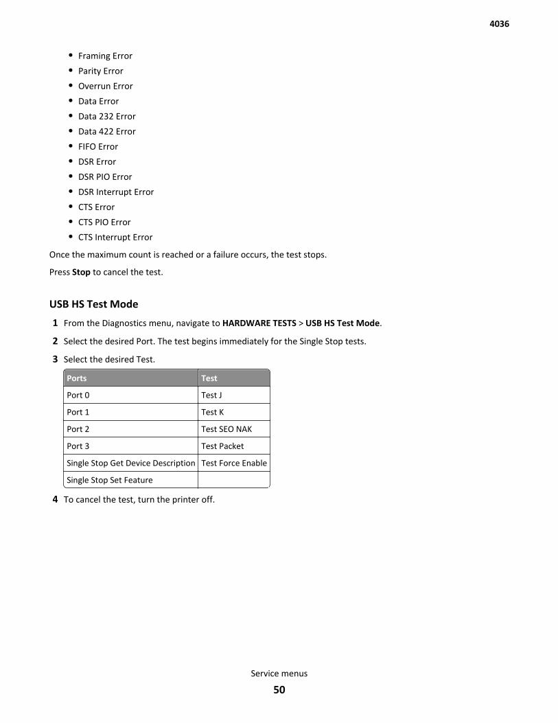
• Framing Error
• Parity Error
• Overrun Error
• Data Error
• Data 232 Error
• Data 422 Error
• FIFO Error
• DSR Error
• DSR PIO Error
• DSR Interrupt Error
• CTS Error
• CTS PIO Error
• CTS Interrupt Error
Once the maximum count is reached or a failure occurs, the test stops.
Press Stop to cancel the test.
USB HS Test Mode
1 From the Diagnostics menu, navigate to HARDWARE TESTS > USB HS Test Mode.
2 Select the desired Port. The test begins immediately for the Single Stop tests.
3 Select the desired Test.
Ports Test
Port 0 Test J
Port 1 Test K
Port 2 Test SEO NAK
Port 3 Test Packet
Single Stop Get Device Description Test Force Enable
Single Stop Set Feature
4 To cancel the test, turn the printer off.
4036
Service menus
50
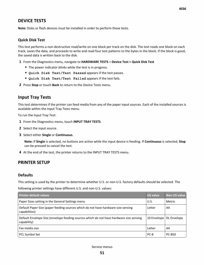
DEVICE TESTSNote: Disks or flash devices must be installed in order to perform these tests.
Quick Disk Test
This test performs a non-destructive read/write on one block per track on the disk. The test reads one block on eachtrack, saves the data, and proceeds to write and read four test patterns to the bytes in the block. If the block is good,the saved data is written back to the disk.
1 From the Diagnostics menu, navigate to HARDWARE TESTS > Device Test > Quick Disk Test
• The power indicator blinks while the test is in progress.
• Quick Disk Test/Test Passed appears if the test passes.
• Quick Disk Test/Test Failed appears if the test fails.
2 Press Stop or touch Back to return to the Device Tests menu.
Input Tray TestsThis test determines if the printer can feed media from any of the paper input sources. Each of the installed sources isavailable within the Input Tray Tests menu.
To run the Input Tray Test:
1 From the Diagnostics menu, touch INPUT TRAY TESTS.
2 Select the input source.
3 Select either Single or Continuous.
Note: If Single is selected, no buttons are active while the input device is feeding. If Continuous is selected, Stopcan be pressed to cancel the test.
4 At the end of the test, the printer returns to the INPUT TRAY TESTS menu.
PRINTER SETUP
Defaults
This setting is used by the printer to determine whether U.S. or non-U.S. factory defaults should be selected. The
following printer settings have different U.S. and non-U.S. values:
Printer default values US value Non‑US value
Paper Sizes setting in the General Settings menu U.S. Metric
Default Paper Size (paper feeding sources which do not have hardware size sensingcapabilities)
Letter A4
Default Envelope Size (envelope feeding sources which do not have hardware size sensingcapability)
10 Envelope DL Envelope
Fax media size Letter A4
PCL Symbol Set PC-8 PC-850
4036
Service menus
51

Printer default values US value Non‑US value
PPDS Code Page 437 850
Universal Units of Measure Inches Millimeters
Modification of the printer setting Defaults causes the NVRAM space to be restored to the printer’s factory settings.
PERM PAGE COUNTS
This menu lets you view the total page counts of the printer or the page counts broken down into color and mono pagesprinted. Unlike in previous printers, none of these values can be changed.
Touch Back to return to the Diagnostics menu.
Serial Number
You can view the serial number.
Engine Setting (1-16)
Warning—Potential Damage: The engine setting should not be changed without specific instructions from the nextlevel of support.
Model Name
You can view the model name.
Configuration ID
The two configuration IDs are used to communicate information about certain areas of the printer that cannot bedetermined using hardware sensors. The configuration IDs are originally set at the factory when the printer ismanufactured. However, you may need to reset Configuration ID 1 or Configuration ID 2 whenever you replace thecontroller board. The IDs consist of eight hexadecimal characters, including 0 through 9 and A through F.
Note: When the printer detects a Configuration ID that is not defined or invalid, the following occur:
• The default standard model Configuration ID is used instead.
• Configuration ID is the only function available in DIAGNOSTICS.
• Unless the menu is in DIAGNOSTICS, Check Config ID appears.
To set the configuration ID:
1 From the Diagnostics menu, navigate to: Printer Setup > Configuration ID
2 Enter the Configuration ID 1.
3 Touch the Configuration ID 2 value to select it, and then enter the new Configuration ID 2.
4 Touch Submit to save and validate the new IDs.
If either ID is invalid, then the printer discards the changes and returns to the original IDs.
If both IDs are valid, then the printer returns to the Diagnostics menu.
4036
Service menus
52
REPORTSFrom this menu you can print the Menu Settings Page or the Event Log.
EVENT LOG
Display Log
Display Log shows the message that appeared on the control panel for each event in the log, starting with the mostrecent. Use the touch-screen arrows to scroll through the log entries. To see more in-depth information about eachevent, print the event log using the Print Log menu item.
Touch Back to return to the EVENT LOG menu.
Print Log
The Print Log menu item prints a detailed report of each event in the log. The first page of the event log contains aPrinter Information section similar to what is printed on a Menu Setting Page. Printed at the top of each page is themodel name and serial number to assist in tracking each page of a report to a specific printer. The printout of the logcontains the following information for each error in the log:
• Page count when the error occurred (except for 900 service controller board software errors).
• Code versions of all packages when error occurred.
• Panel message when error occurred (except for 900 service controller board software errors).
• Debug information and secondary error codes, depending on the error.
The Clear Log operation clears out the errors that print in this report. The errors listed in the Display Log operation donot necessarily match in number or in order with the errors from the printer log.
Note: This log can be printed from configuration menu, but the debug and secondary error codes are not printed onthis log.
Clear Log
This menu item deletes the event log. Once the event log is deleted, the only item remaining on the log is the “ClearLog” event.
Touch Back to return to the EVENT LOG menu.
SCANNER TESTS
Scanner Calibration Reset
This option resets the scanner calibration values to factory default settings. This should be done after you replace theflatbed scanner unit.
Note: Be sure the scanner glass and backing material are clean before performing this test.
ASIC Test
This test initiates a scan of the scanner ASIC memory. This is a pass/fail test.
4036
Service menus
53
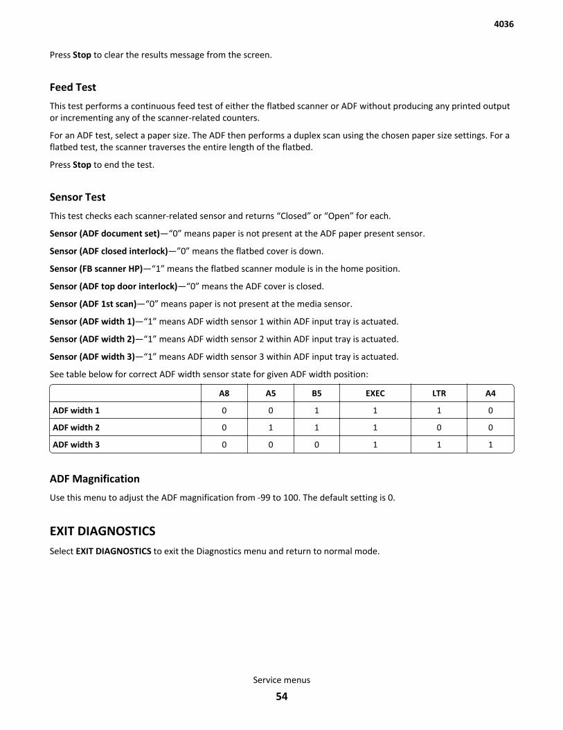
Press Stop to clear the results message from the screen.
Feed Test
This test performs a continuous feed test of either the flatbed scanner or ADF without producing any printed outputor incrementing any of the scanner-related counters.
For an ADF test, select a paper size. The ADF then performs a duplex scan using the chosen paper size settings. For aflatbed test, the scanner traverses the entire length of the flatbed.
Press Stop to end the test.
Sensor Test
This test checks each scanner-related sensor and returns “Closed” or “Open” for each.
Sensor (ADF document set)—“0” means paper is not present at the ADF paper present sensor.
Sensor (ADF closed interlock)—”0” means the flatbed cover is down.
Sensor (FB scanner HP)—“1” means the flatbed scanner module is in the home position.
Sensor (ADF top door interlock)—“0” means the ADF cover is closed.
Sensor (ADF 1st scan)—“0” means paper is not present at the media sensor.
Sensor (ADF width 1)—“1” means ADF width sensor 1 within ADF input tray is actuated.
Sensor (ADF width 2)—“1” means ADF width sensor 2 within ADF input tray is actuated.
Sensor (ADF width 3)—“1” means ADF width sensor 3 within ADF input tray is actuated.
See table below for correct ADF width sensor state for given ADF width position:
A8 A5 B5 EXEC LTR A4
ADF width 1 0 0 1 1 1 0
ADF width 2 0 1 1 1 0 0
ADF width 3 0 0 0 1 1 1
ADF Magnification
Use this menu to adjust the ADF magnification from -99 to 100. The default setting is 0.
EXIT DIAGNOSTICSSelect EXIT DIAGNOSTICS to exit the Diagnostics menu and return to normal mode.
4036
Service menus
54
Adjustments
Calibrating the scannerAfter replacing any of the following components, you must reset the relevant scanner calibration values and check theblack levels of the scanner:
• Flatbed scanner module assembly
• Front ADF scanner module assembly
• Back ADF scanner module assembly
• Controller board
Resetting the calibration values
Note: If the scanner menus do not match the following instructions, then contact your next level of support.
1 Enter the Diagnostic mode: press and hold 3 and 6, turn on the printer, and release the buttons when the splashscreen appears.
2 From the Diagnostics menu, navigate to: Scanner Calibration > Reset (relevant assembly) Calibration Values.
Adjusting the scanner black and white levels
Notes:
• If the scanner menus do not match the following instructions, then contact your next level of support.
• For best results, use media with a minimum weight of 24lb and minimum brightness of 92 for the followingprocedures.
1 From the Diagnostic menu, navigate to: Scanner Calibration > Print Testcase.
4036
Service menus
55
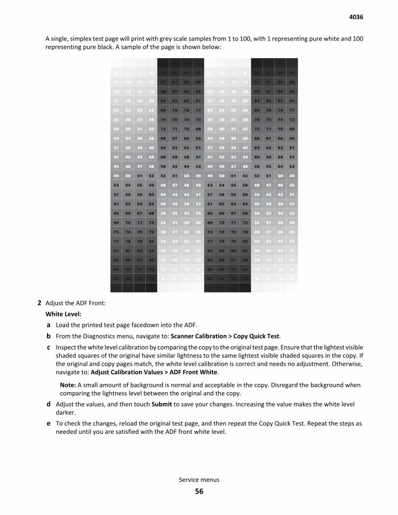
A single, simplex test page will print with grey scale samples from 1 to 100, with 1 representing pure white and 100representing pure black. A sample of the page is shown below:
2 Adjust the ADF Front:
White Level:
a Load the printed test page facedown into the ADF.
b From the Diagnostics menu, navigate to: Scanner Calibration > Copy Quick Test.
c Inspect the white level calibration by comparing the copy to the original test page. Ensure that the lightest visibleshaded squares of the original have similar lightness to the same lightest visible shaded squares in the copy. Ifthe original and copy pages match, the white level calibration is correct and needs no adjustment. Otherwise,navigate to: Adjust Calibration Values > ADF Front White.
Note: A small amount of background is normal and acceptable in the copy. Disregard the background whencomparing the lightness level between the original and the copy.
d Adjust the values, and then touch Submit to save your changes. Increasing the value makes the white leveldarker.
e To check the changes, reload the original test page, and then repeat the Copy Quick Test. Repeat the steps asneeded until you are satisfied with the ADF front white level.
4036
Service menus
56
Black Level:
a Load the printed test page facedown into the ADF.
b From the Diagnostics menu, navigate to: Scanner Calibration > Copy Quick Test.
c Inspect the black level calibration by assessing the toner saturation of the darkest square of the copy. Theobjective of the black level calibration is to find the minimum numeric setting that provides the maximum tonersaturation of the darkest square. Too high of a setting will cause other dark squares to become fully black. Toolow of a setting will result in the darkest square not being as dark as possible.
d Navigate to: Adjust Calibration Values > ADF Front Black. If the darkest square of the copy page does not appearfully saturated, then increase the value. If several of the darkest squares look equally saturated, then decreasethe value. Select Submit to save your changes, reload the original test page, and repeat the Copy Quick Test.Inspect the copy page again and repeat this step until the single darkest square is fully saturated, and none ofthe other dark squares are as dark as the darkest square.
3 Adjust the ADF Back:
White Level:
a Load the printed test page faceup into the ADF.
b From the Diagnostics menu, navigate to: Scanner Calibration > Copy Quick Test.
c Inspect the white level calibration by comparing the copy to the original test page. Ensure that the lightest visibleshaded squares of the original have similar lightness to the same lightest visible shaded squares in the copy. Ifthe original and copy pages match, then the white level calibration is correct and needs no adjustment.Otherwise, navigate to: Adjust Calibration Values > ADF Back White.
Note: A small amount of background is normal and acceptable in the copy. Disregard the background whencomparing the lightness level between the original and the copy.
d Adjust the values, and then touch Submit to save your changes. Increasing the value makes the white leveldarker.
e To check the changes, reload the original test page, and then repeat the Copy Quick Test. Repeat the steps asneeded until you are satisfied with the ADF back white level.
Black Level:
a Load the printed test page faceup into the ADF.
b From the Diagnostics menu, navigate to: Scanner Calibration > Copy Quick Test.
c Inspect the black level calibration by assessing the toner saturation of the darkest square of the copy. Theobjective of the black level calibration is to find the minimum numeric setting that provides the maximum tonersaturation of the darkest square. Too high of a setting will cause other dark squares to become fully black. Toolow of a setting will result in the darkest square not being as dark as possible.
d Navigate to: Adjust Calibration Values > ADF Back Black. If the darkest square of the copy page does not appearfully saturated, then increase the value. If several of the darkest squares look equally saturated, then decreasethe value. Select Submit to save your changes, reload the original test page, and repeat the Copy Quick Test.Inspect the copy page again and repeat this step until the single darkest square is fully saturated, and none ofthe other dark squares are as dark as the darkest square.
4 Adjust the Flatbed:
White Level:
a Remove all pages from the ADF, then load the printed test page facedown onto the flatbed.
b From the Diagnostics menu, navigate to: Scanner Calibration > Copy Quick Test.
4036
Service menus
57
c Inspect the white level calibration by comparing the copy to the original test page. Ensure that the lightest visibleshaded squares of the original have similar lightness to the same lightest visible shaded squares in the copy. Ifthe original and copy pages match, the white level calibration is correct and needs no adjustment. Otherwise,navigate to: Adjust Calibration Values > Flatbed White.
Note: A small amount of background is normal and acceptable in the copy. Disregard the background whencomparing the lightness level between the original and the copy.
d Adjust the values, and then touch Submit to save your changes. Increasing the value makes the white leveldarker.
e To check the changes, reload the original test page, and then repeat the Copy Quick Test. Repeat the steps asneeded until you are satisfied with the flatbed white level.
Black Level:
a Remove all pages from the ADF, then load the printed test page facedown onto the flatbed.
b From the Diagnostics menu, navigate to: Scanner Calibration > Copy Quick Test.
c Inspect the black level calibration by assessing the toner saturation of the darkest square of the copy. Theobjective of the black level calibration is to find the minimum numeric setting that provides the maximum tonersaturation of the darkest square. Too high of a setting will cause other dark squares to become fully black. Toolow of a setting will result in the darkest square not being as dark as possible.
Note: A small amount of background is normal and acceptable in the copy. Disregard the background whencomparing the lightness level between the original and the copy.
d Navigate to: Adjust Calibration Values > Flatbed Black. If the darkest square of the copy page does not appearfully saturated, then increase the value. If several of the darkest squares look equally saturated, then decreasethe value. Select Submit to save your changes, reload the original test page, and repeat the Copy Quick Test.Inspect the copy page again and repeat this step until the single darkest square is fully saturated, and none ofthe other dark squares are as dark as the darkest square.
Calibrating the multifeed sensorIn order for the multifeed sensor to function properly and to detect the presence of multifeed media, the sensor mustbe properly calibrated. Any time a new multifeed sensor is replaced, this procedure must be followed:
1 Open the ADF, and remove the separator pad. Close the ADF.
2 Obtain a multifeed sensor calibration sheet (included with the multifeed sensor FRU), and fold it in half such thatthe short edges overlap each other.
3 Load the multifeed sensor calibration sheet into the ADF with the folded edge first.
4 Enter the Diagnostic Mode and select Scanner Tests > Ultrasonic Multifeed Sensor Calibration.
5 Press the Submit button to begin the calibration procedure. The calibration sheet will be fed into the ADF.
The test will report if the calibration procedure passed or failed. If the test reports “Passed,” then the calibration processis successfully complete. If the test reports “Failed,” then the calibration process failed to complete. If the calibrationtest fails, then check the following:
• Make sure the separator pad is removed.
• Make sure the calibration page is folded over and feeding into the ADF as two sheets.
• If the problem continues, then make sure the multifeed sensor is properly installed and the cables are connected.if the problem continues, then replace the multifeed sensor. See “Multifeed sensor removal” on page 92.
4036
Service menus
58
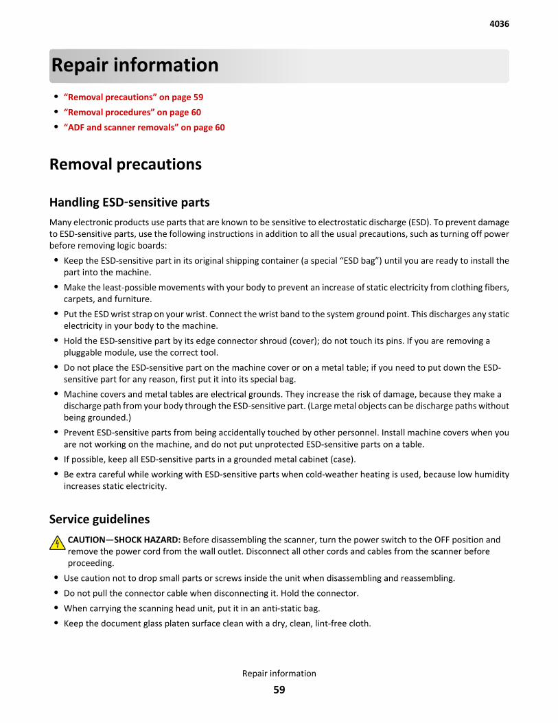
Repair information• “Removal precautions” on page 59
• “Removal procedures” on page 60
• “ADF and scanner removals” on page 60
Removal precautions
Handling ESD‑sensitive partsMany electronic products use parts that are known to be sensitive to electrostatic discharge (ESD). To prevent damageto ESD-sensitive parts, use the following instructions in addition to all the usual precautions, such as turning off powerbefore removing logic boards:
• Keep the ESD-sensitive part in its original shipping container (a special “ESD bag”) until you are ready to install thepart into the machine.
• Make the least-possible movements with your body to prevent an increase of static electricity from clothing fibers,carpets, and furniture.
• Put the ESD wrist strap on your wrist. Connect the wrist band to the system ground point. This discharges any staticelectricity in your body to the machine.
• Hold the ESD-sensitive part by its edge connector shroud (cover); do not touch its pins. If you are removing apluggable module, use the correct tool.
• Do not place the ESD-sensitive part on the machine cover or on a metal table; if you need to put down the ESD-sensitive part for any reason, first put it into its special bag.
• Machine covers and metal tables are electrical grounds. They increase the risk of damage, because they make adischarge path from your body through the ESD-sensitive part. (Large metal objects can be discharge paths withoutbeing grounded.)
• Prevent ESD-sensitive parts from being accidentally touched by other personnel. Install machine covers when youare not working on the machine, and do not put unprotected ESD-sensitive parts on a table.
• If possible, keep all ESD-sensitive parts in a grounded metal cabinet (case).
• Be extra careful while working with ESD-sensitive parts when cold-weather heating is used, because low humidityincreases static electricity.
Service guidelinesCAUTION—SHOCK HAZARD: Before disassembling the scanner, turn the power switch to the OFF position andremove the power cord from the wall outlet. Disconnect all other cords and cables from the scanner beforeproceeding.
• Use caution not to drop small parts or screws inside the unit when disassembling and reassembling.
• Do not pull the connector cable when disconnecting it. Hold the connector.
• When carrying the scanning head unit, put it in an anti-static bag.
• Keep the document glass platen surface clean with a dry, clean, lint-free cloth.
4036
Repair information
59
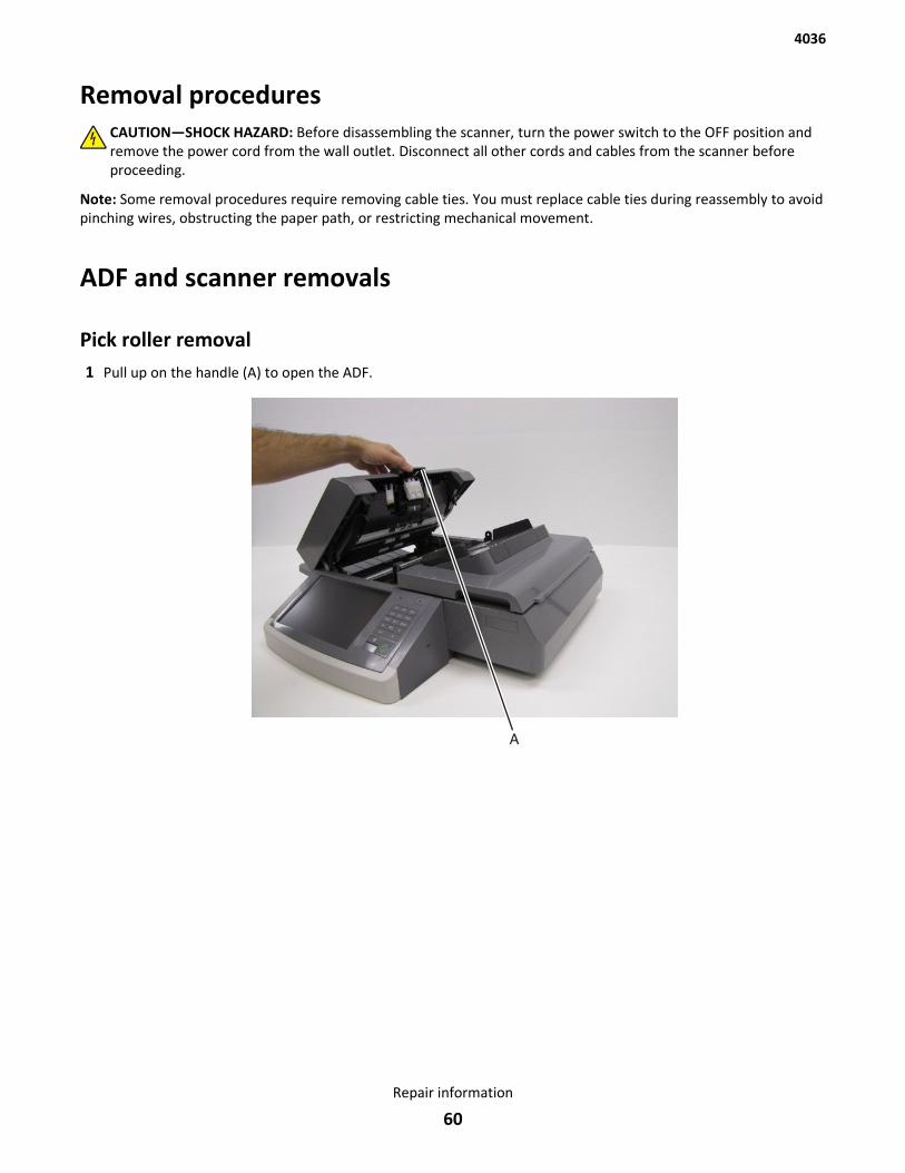
Removal proceduresCAUTION—SHOCK HAZARD: Before disassembling the scanner, turn the power switch to the OFF position andremove the power cord from the wall outlet. Disconnect all other cords and cables from the scanner beforeproceeding.
Note: Some removal procedures require removing cable ties. You must replace cable ties during reassembly to avoidpinching wires, obstructing the paper path, or restricting mechanical movement.
ADF and scanner removals
Pick roller removal1 Pull up on the handle (A) to open the ADF.
4036
Repair information
60
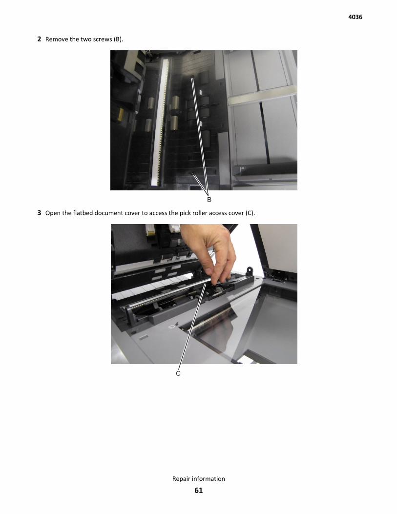
2 Remove the two screws (B).
3 Open the flatbed document cover to access the pick roller access cover (C).
4036
Repair information
61
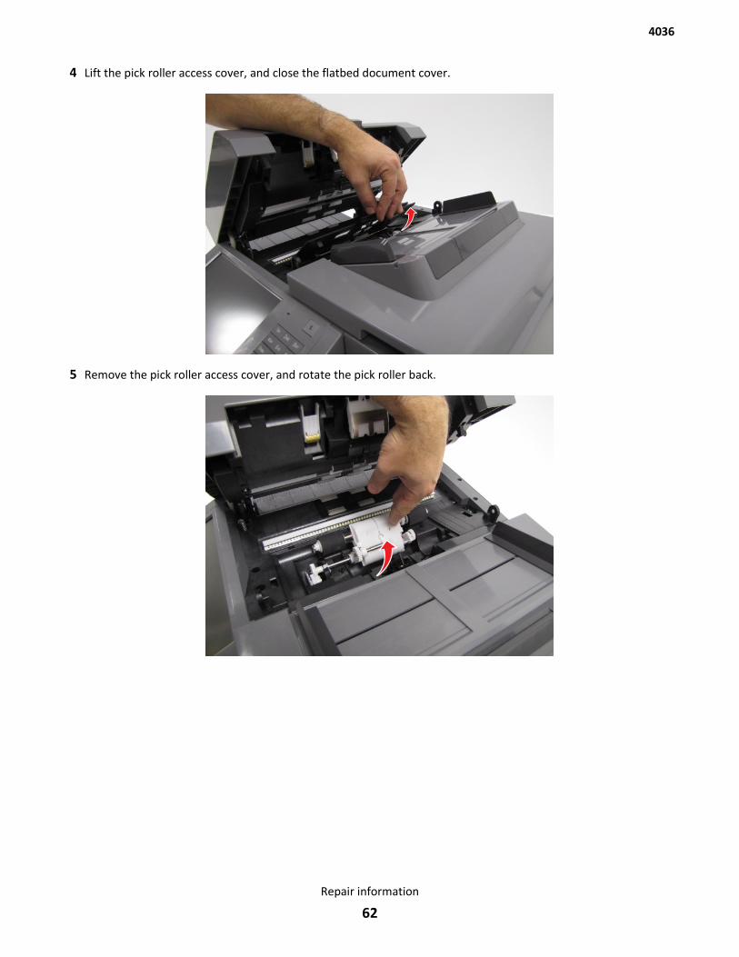
4 Lift the pick roller access cover, and close the flatbed document cover.
5 Remove the pick roller access cover, and rotate the pick roller back.
4036
Repair information
62
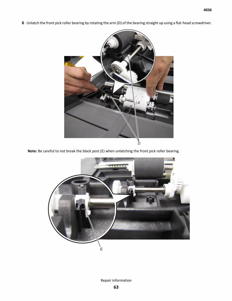
6 Unlatch the front pick roller bearing by rotating the arm (D) of the bearing straight up using a flat‑head screwdriver.
Note: Be careful to not break the black post (E) when unlatching the front pick roller bearing.
4036
Repair information
63
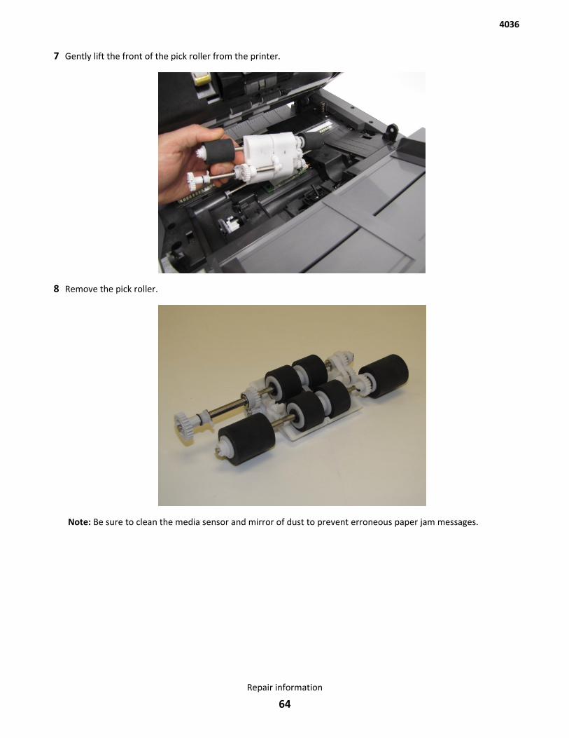
7 Gently lift the front of the pick roller from the printer.
8 Remove the pick roller.
Note: Be sure to clean the media sensor and mirror of dust to prevent erroneous paper jam messages.
4036
Repair information
64
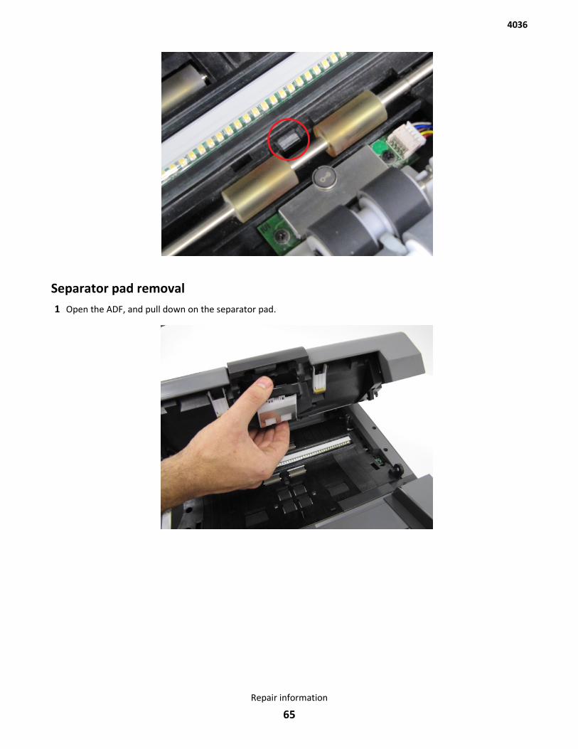
Separator pad removal1 Open the ADF, and pull down on the separator pad.
4036
Repair information
65
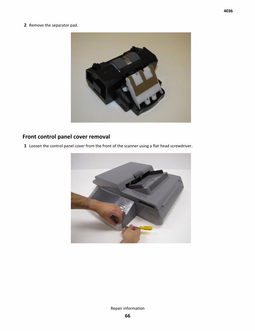
2 Remove the separator pad.
Front control panel cover removal1 Loosen the control panel cover from the front of the scanner using a flat‑head screwdriver.
4036
Repair information
66
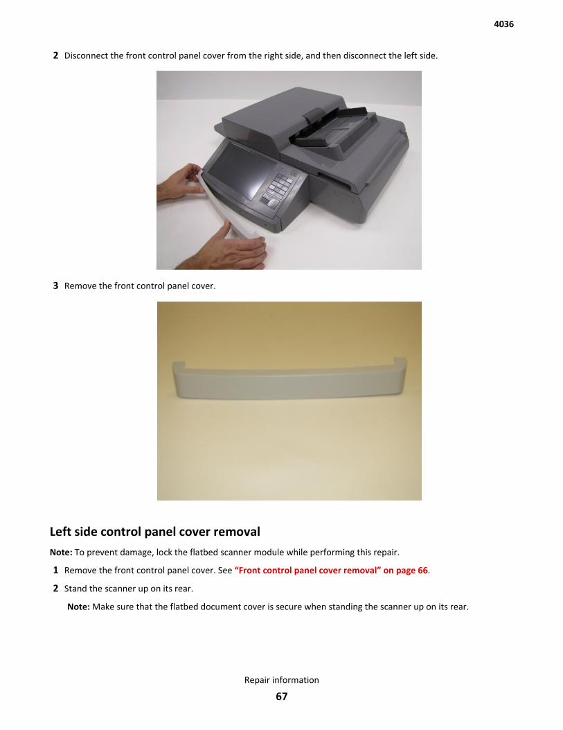
2 Disconnect the front control panel cover from the right side, and then disconnect the left side.
3 Remove the front control panel cover.
Left side control panel cover removalNote: To prevent damage, lock the flatbed scanner module while performing this repair.
1 Remove the front control panel cover. See “Front control panel cover removal” on page 66.
2 Stand the scanner up on its rear.
Note: Make sure that the flatbed document cover is secure when standing the scanner up on its rear.
4036
Repair information
67
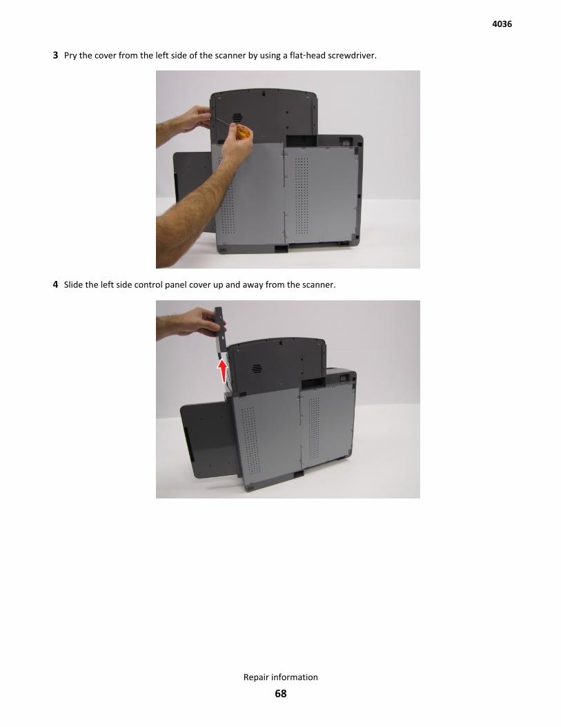
3 Pry the cover from the left side of the scanner by using a flat‑head screwdriver.
4 Slide the left side control panel cover up and away from the scanner.
4036
Repair information
68
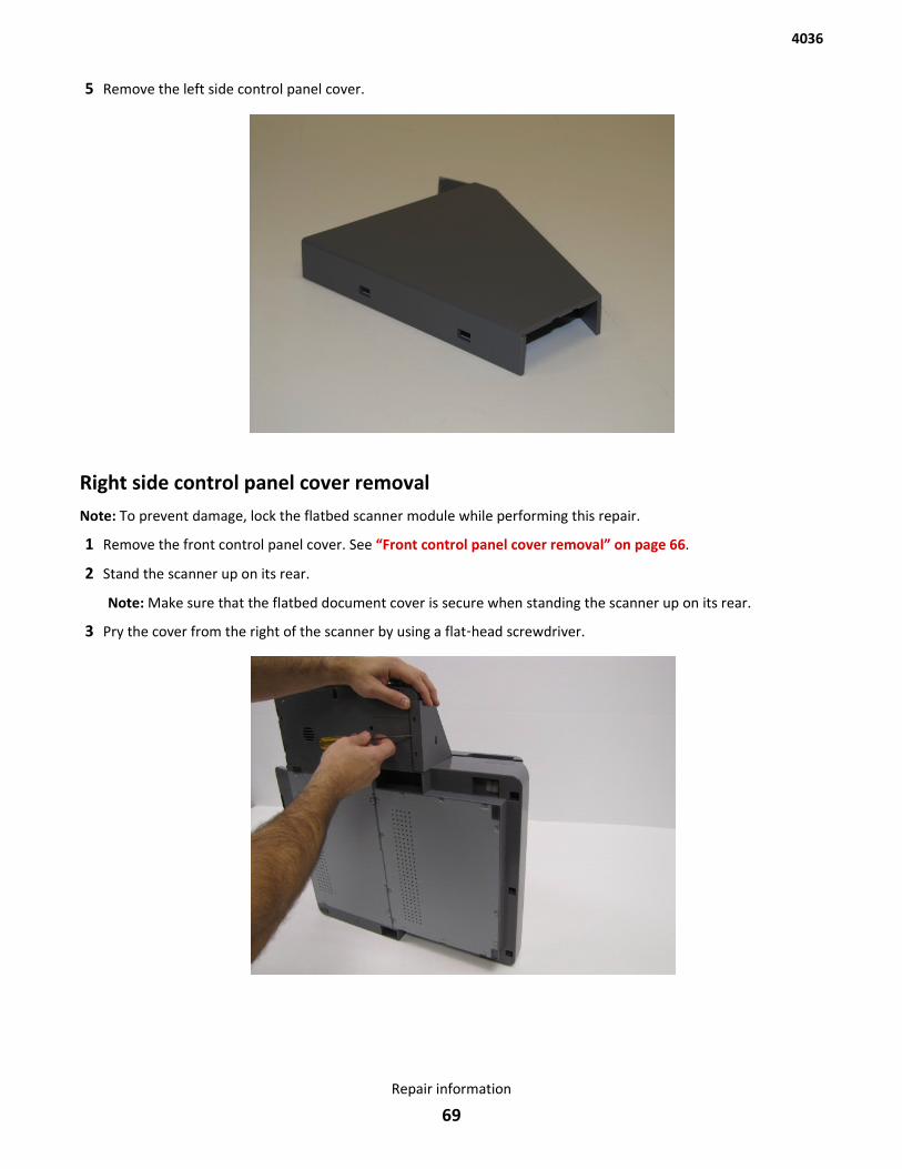
5 Remove the left side control panel cover.
Right side control panel cover removalNote: To prevent damage, lock the flatbed scanner module while performing this repair.
1 Remove the front control panel cover. See “Front control panel cover removal” on page 66.
2 Stand the scanner up on its rear.
Note: Make sure that the flatbed document cover is secure when standing the scanner up on its rear.
3 Pry the cover from the right of the scanner by using a flat‑head screwdriver.
4036
Repair information
69
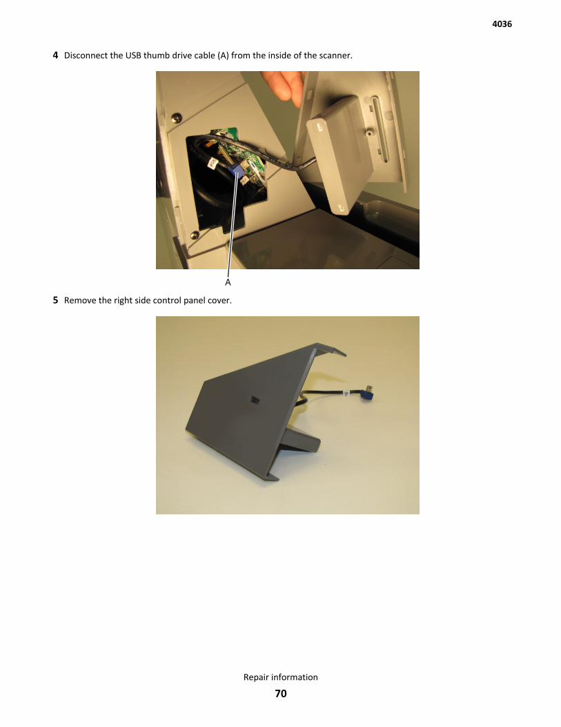
4 Disconnect the USB thumb drive cable (A) from the inside of the scanner.
5 Remove the right side control panel cover.
4036
Repair information
70
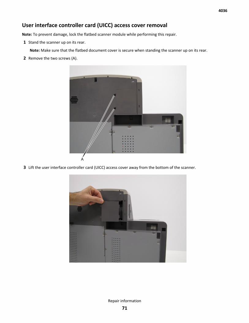
User interface controller card (UICC) access cover removalNote: To prevent damage, lock the flatbed scanner module while performing this repair.
1 Stand the scanner up on its rear.
Note: Make sure that the flatbed document cover is secure when standing the scanner up on its rear.
2 Remove the two screws (A).
3 Lift the user interface controller card (UICC) access cover away from the bottom of the scanner.
4036
Repair information
71

4 Remove the user interface controller card (UICC) access cover.
Control panel assembly removalNote: To prevent damage, lock the flatbed scanner module while performing this repair.
1 Remove the front control panel cover. See “Front control panel cover removal” on page 66.
2 Remove the left side control panel cover. See “Left side control panel cover removal” on page 67.
3 Remove the right side control panel cover. See “Right side control panel cover removal” on page 69.
4 Remove the one screw (A) from the bottom of the scanner.
5 Remove the two screws (B) from the left side of the scanner and the two screws (C) from the right side of thescanner.
4036
Repair information
72
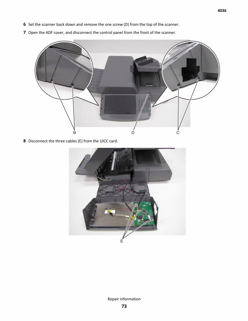
6 Set the scanner back down and remove the one screw (D) from the top of the scanner.
7 Open the ADF cover, and disconnect the control panel from the front of the scanner.
8 Disconnect the three cables (E) from the UICC card.
4036
Repair information
73
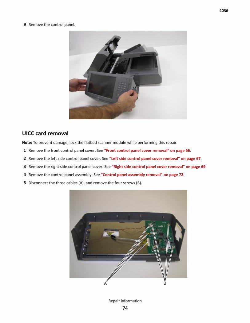
9 Remove the control panel.
UICC card removalNote: To prevent damage, lock the flatbed scanner module while performing this repair.
1 Remove the front control panel cover. See “Front control panel cover removal” on page 66.
2 Remove the left side control panel cover. See “Left side control panel cover removal” on page 67.
3 Remove the right side control panel cover. See “Right side control panel cover removal” on page 69.
4 Remove the control panel assembly. See “Control panel assembly removal” on page 72.
5 Disconnect the three cables (A), and remove the four screws (B).
4036
Repair information
74
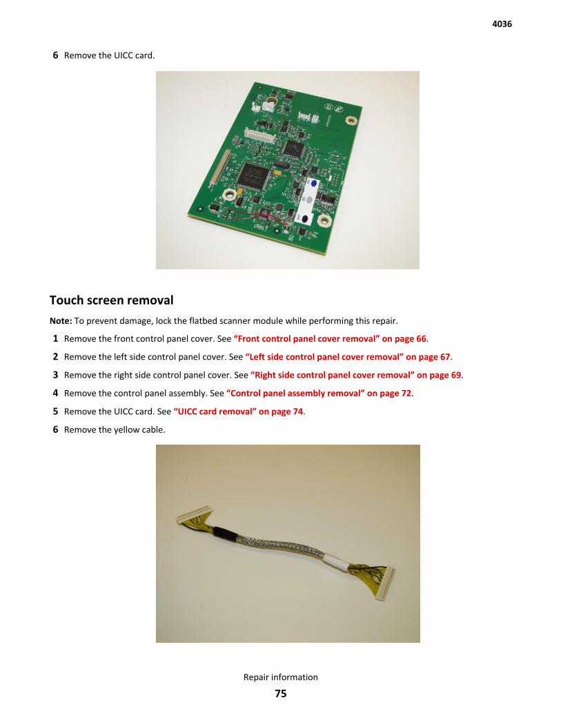
6 Remove the UICC card.
Touch screen removalNote: To prevent damage, lock the flatbed scanner module while performing this repair.
1 Remove the front control panel cover. See “Front control panel cover removal” on page 66.
2 Remove the left side control panel cover. See “Left side control panel cover removal” on page 67.
3 Remove the right side control panel cover. See “Right side control panel cover removal” on page 69.
4 Remove the control panel assembly. See “Control panel assembly removal” on page 72.
5 Remove the UICC card. See “UICC card removal” on page 74.
6 Remove the yellow cable.
4036
Repair information
75
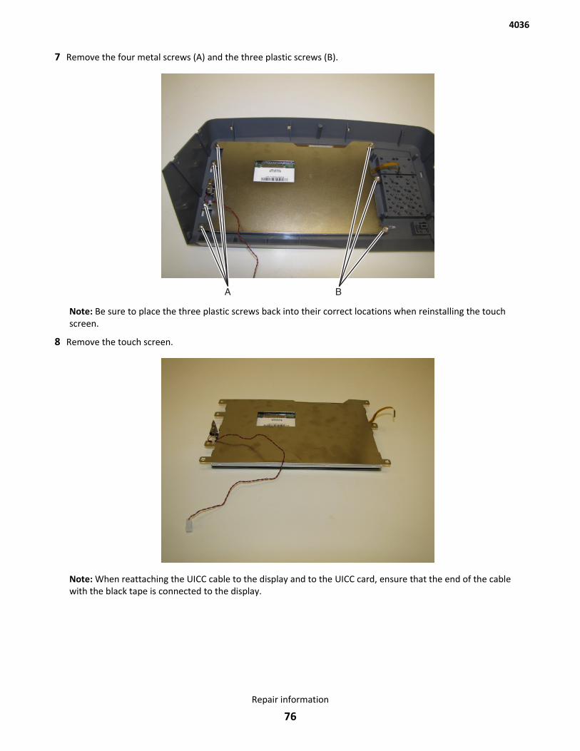
7 Remove the four metal screws (A) and the three plastic screws (B).
Note: Be sure to place the three plastic screws back into their correct locations when reinstalling the touchscreen.
8 Remove the touch screen.
Note: When reattaching the UICC cable to the display and to the UICC card, ensure that the end of the cablewith the black tape is connected to the display.
4036
Repair information
76
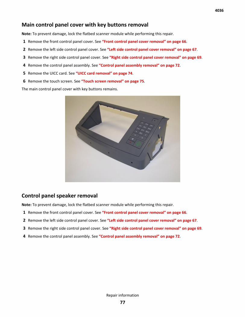
Main control panel cover with key buttons removalNote: To prevent damage, lock the flatbed scanner module while performing this repair.
1 Remove the front control panel cover. See “Front control panel cover removal” on page 66.
2 Remove the left side control panel cover. See “Left side control panel cover removal” on page 67.
3 Remove the right side control panel cover. See “Right side control panel cover removal” on page 69.
4 Remove the control panel assembly. See “Control panel assembly removal” on page 72.
5 Remove the UICC card. See “UICC card removal” on page 74.
6 Remove the touch screen. See “Touch screen removal” on page 75.
The main control panel cover with key buttons remains.
Control panel speaker removalNote: To prevent damage, lock the flatbed scanner module while performing this repair.
1 Remove the front control panel cover. See “Front control panel cover removal” on page 66.
2 Remove the left side control panel cover. See “Left side control panel cover removal” on page 67.
3 Remove the right side control panel cover. See “Right side control panel cover removal” on page 69.
4 Remove the control panel assembly. See “Control panel assembly removal” on page 72.
4036
Repair information
77
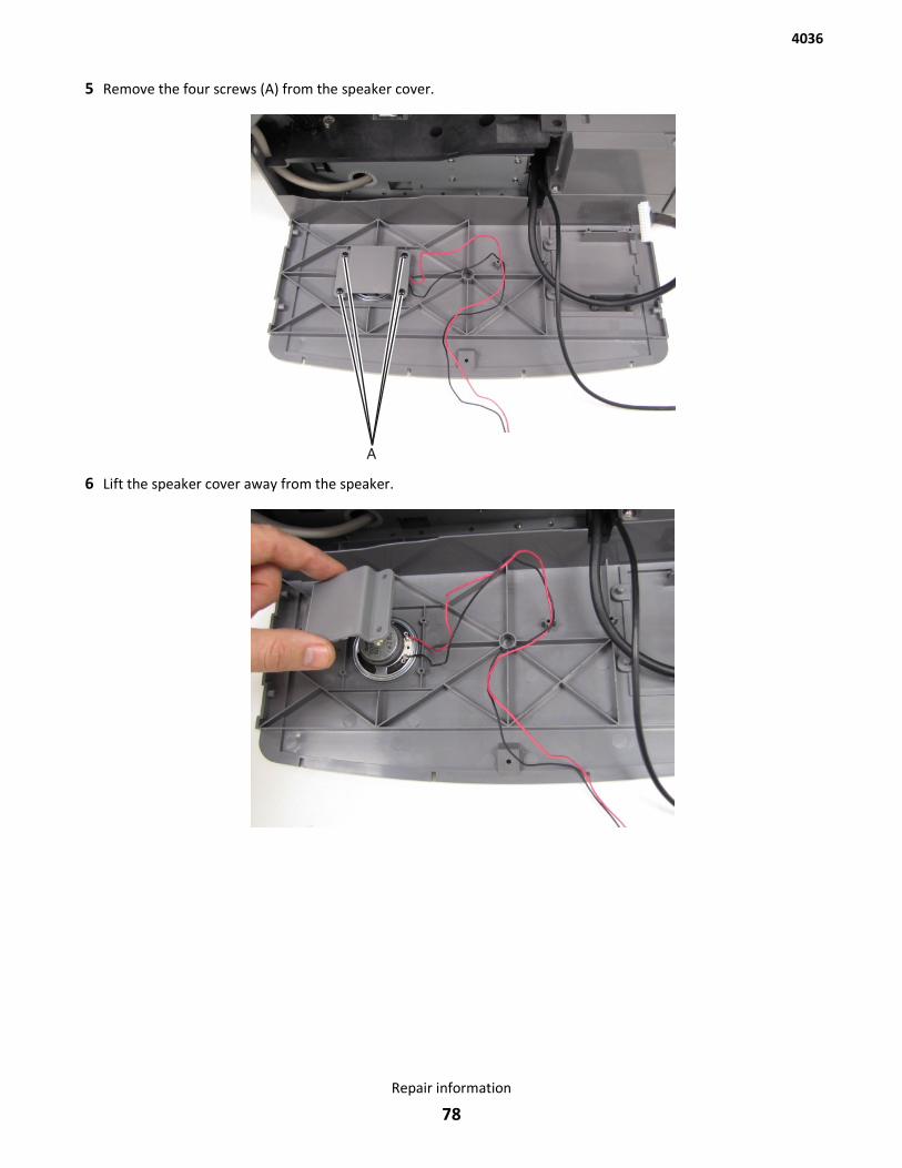
5 Remove the four screws (A) from the speaker cover.
6 Lift the speaker cover away from the speaker.
4036
Repair information
78
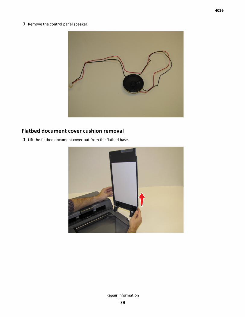
7 Remove the control panel speaker.
Flatbed document cover cushion removal1 Lift the flatbed document cover out from the flatbed base.
4036
Repair information
79
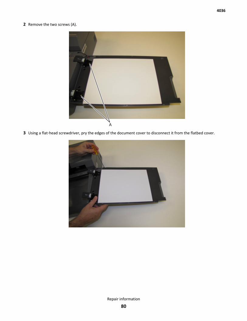
2 Remove the two screws (A).
3 Using a flat‑head screwdriver, pry the edges of the document cover to disconnect it from the flatbed cover.
4036
Repair information
80
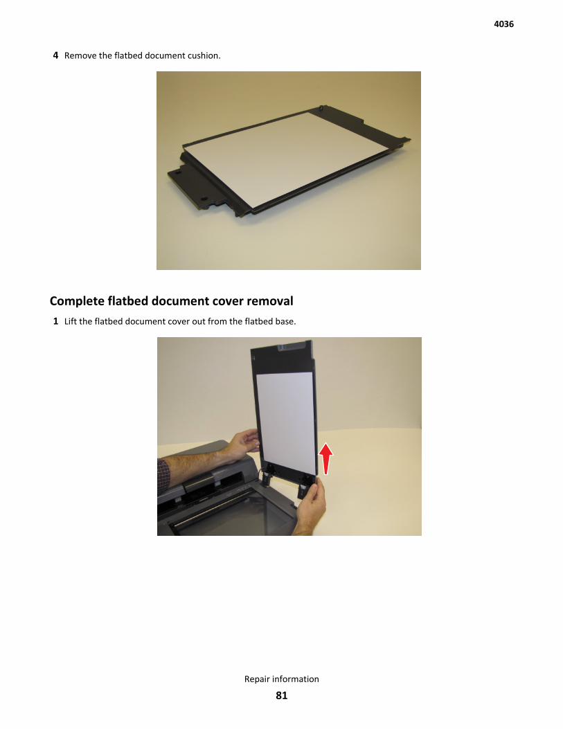
4 Remove the flatbed document cushion.
Complete flatbed document cover removal1 Lift the flatbed document cover out from the flatbed base.
4036
Repair information
81
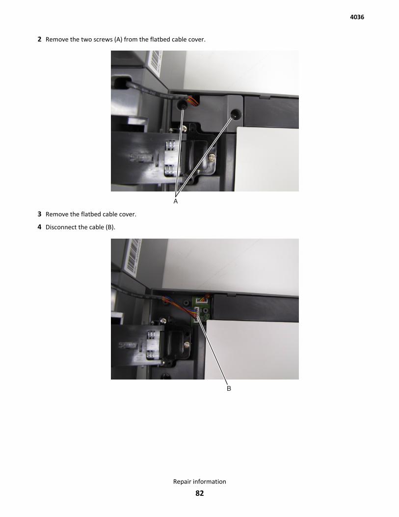
2 Remove the two screws (A) from the flatbed cable cover.
3 Remove the flatbed cable cover.
4 Disconnect the cable (B).
4036
Repair information
82
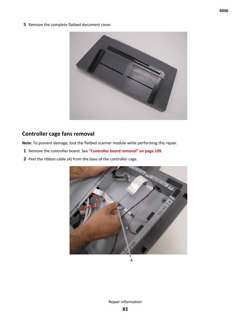
5 Remove the complete flatbed document cover.
Controller cage fans removalNote: To prevent damage, lock the flatbed scanner module while performing this repair.
1 Remove the controller board. See “Controller board removal” on page 109.
2 Peel the ribbon cable (A) from the base of the controller cage.
4036
Repair information
83
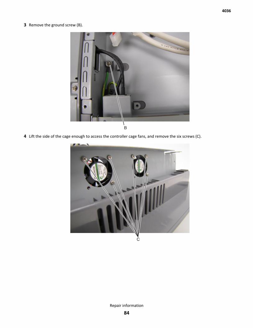
3 Remove the ground screw (B).
4 Lift the side of the cage enough to access the controller cage fans, and remove the six screws (C).
4036
Repair information
84
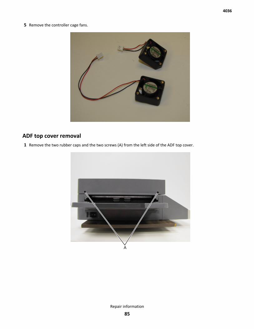
5 Remove the controller cage fans.
ADF top cover removal1 Remove the two rubber caps and the two screws (A) from the left side of the ADF top cover.
4036
Repair information
85
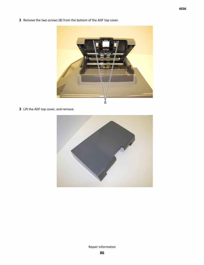
2 Remove the two screws (B) from the bottom of the ADF top cover.
3 Lift the ADF top cover, and remove.
4036
Repair information
86
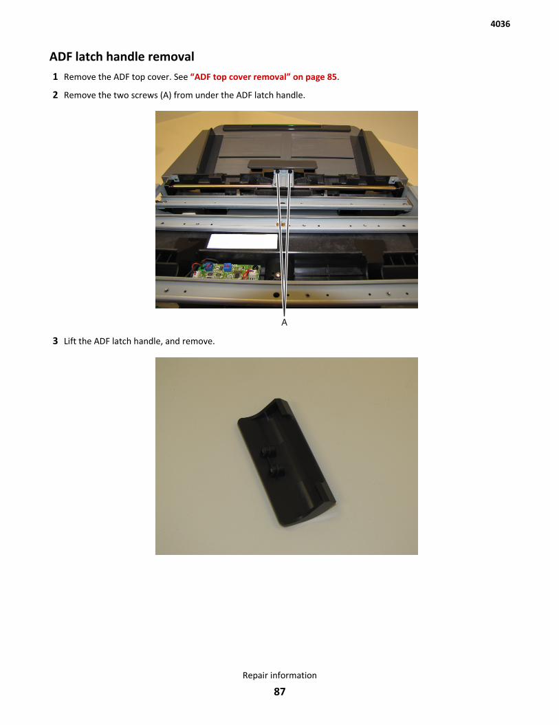
ADF latch handle removal1 Remove the ADF top cover. See “ADF top cover removal” on page 85.
2 Remove the two screws (A) from under the ADF latch handle.
3 Lift the ADF latch handle, and remove.
4036
Repair information
87
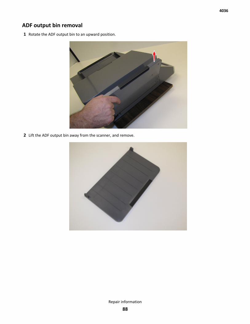
ADF output bin removal1 Rotate the ADF output bin to an upward position.
2 Lift the ADF output bin away from the scanner, and remove.
4036
Repair information
88
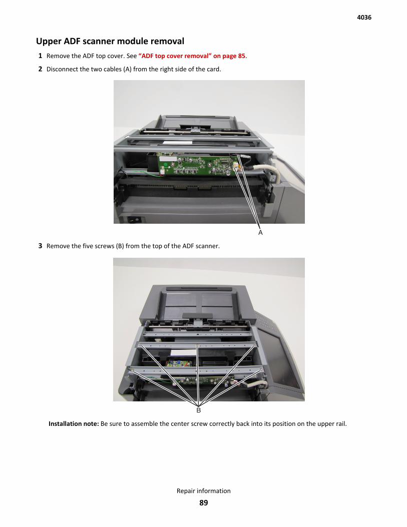
Upper ADF scanner module removal1 Remove the ADF top cover. See “ADF top cover removal” on page 85.
2 Disconnect the two cables (A) from the right side of the card.
3 Remove the five screws (B) from the top of the ADF scanner.
Installation note: Be sure to assemble the center screw correctly back into its position on the upper rail.
4036
Repair information
89
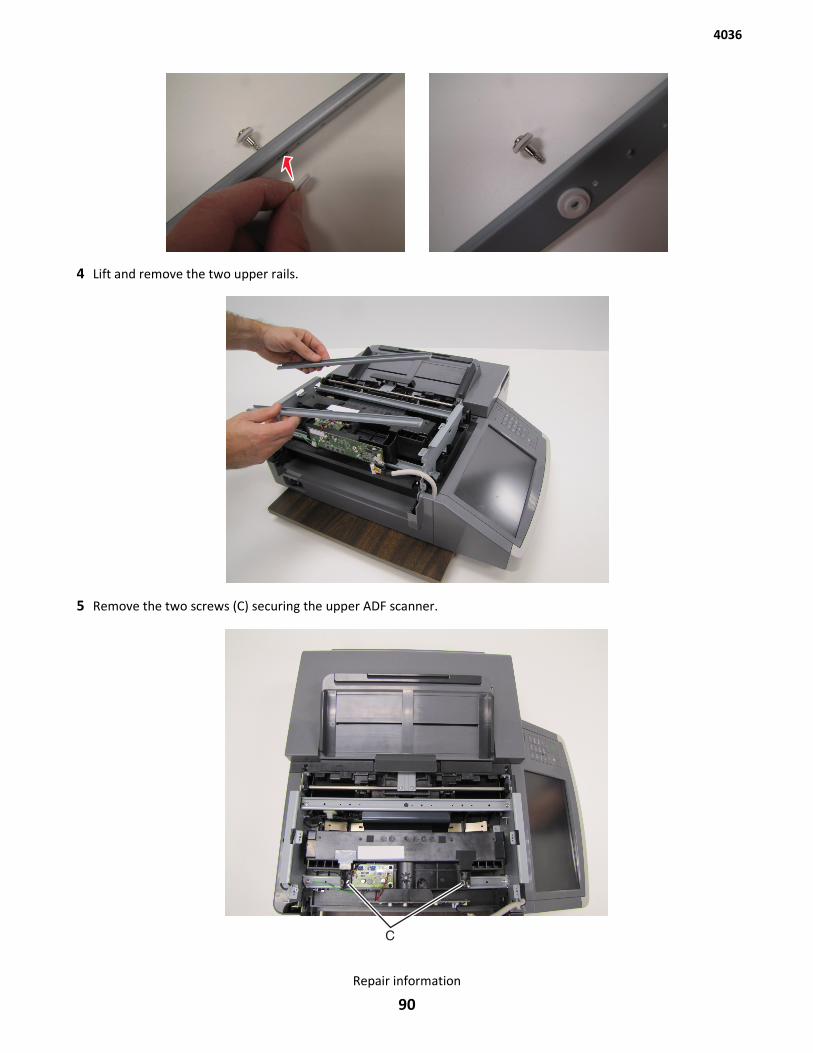
4 Lift and remove the two upper rails.
5 Remove the two screws (C) securing the upper ADF scanner.
4036
Repair information
90
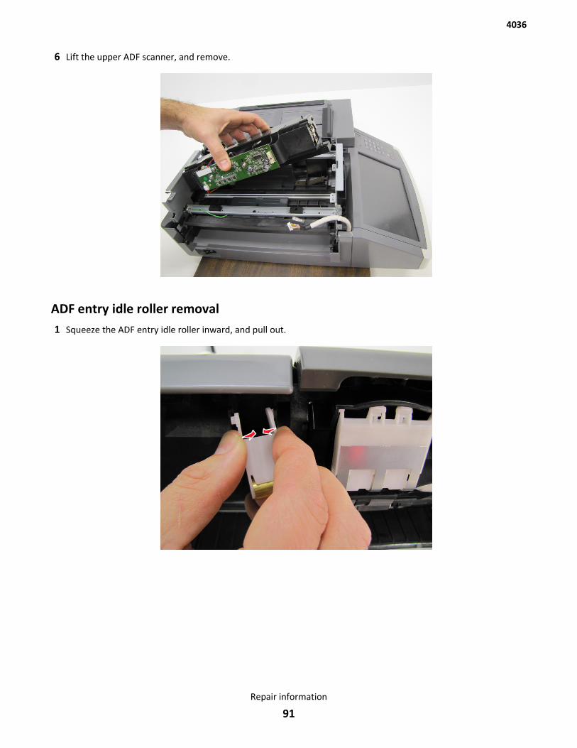
6 Lift the upper ADF scanner, and remove.
ADF entry idle roller removal1 Squeeze the ADF entry idle roller inward, and pull out.
4036
Repair information
91
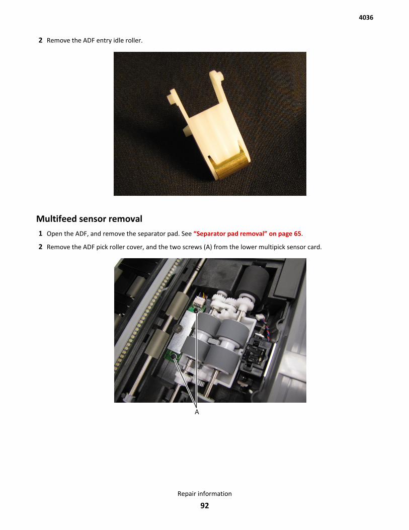
2 Remove the ADF entry idle roller.
Multifeed sensor removal1 Open the ADF, and remove the separator pad. See “Separator pad removal” on page 65.
2 Remove the ADF pick roller cover, and the two screws (A) from the lower multipick sensor card.
4036
Repair information
92
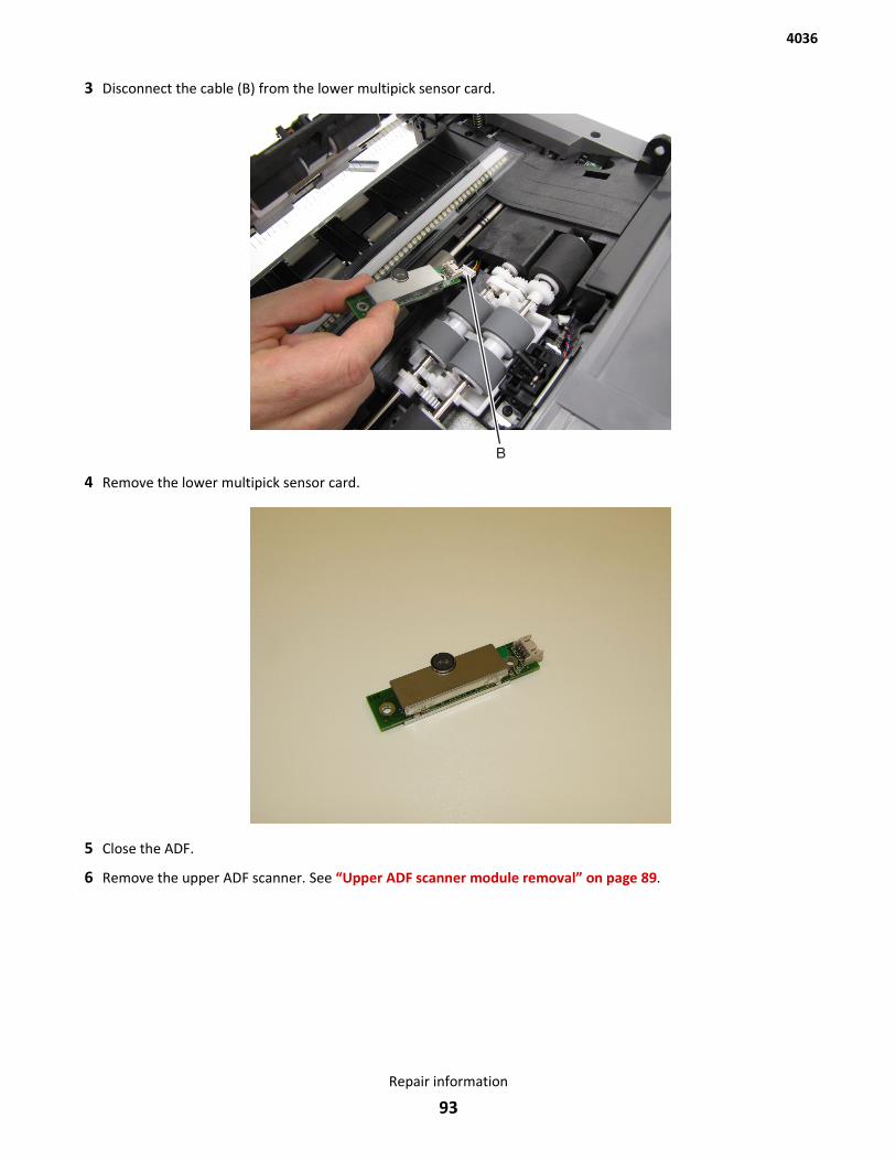
3 Disconnect the cable (B) from the lower multipick sensor card.
4 Remove the lower multipick sensor card.
5 Close the ADF.
6 Remove the upper ADF scanner. See “Upper ADF scanner module removal” on page 89.
4036
Repair information
93
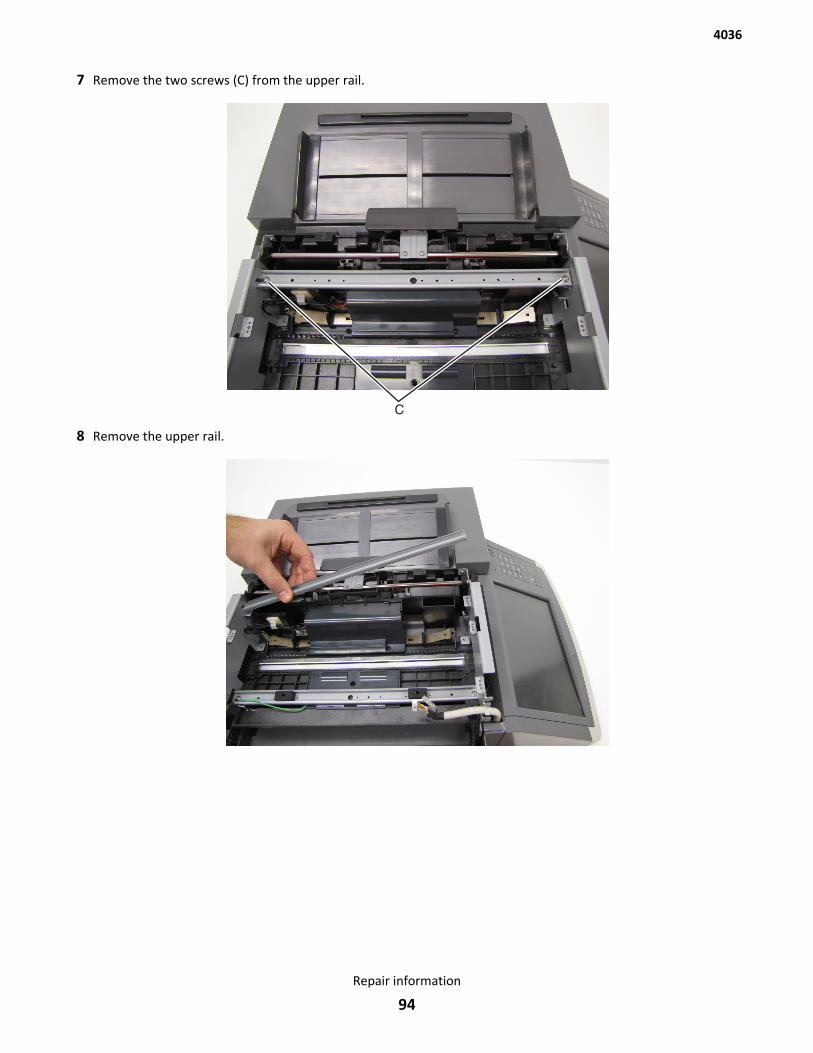
7 Remove the two screws (C) from the upper rail.
8 Remove the upper rail.
4036
Repair information
94
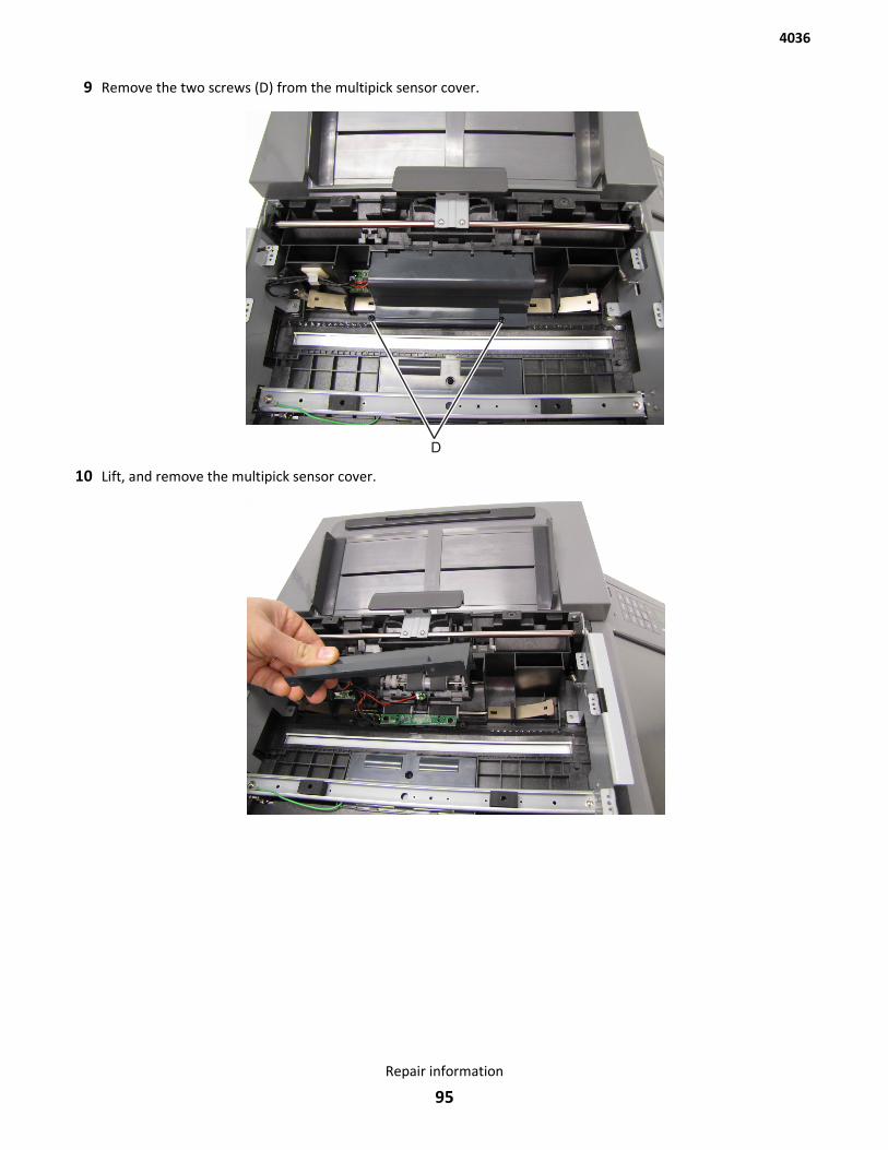
9 Remove the two screws (D) from the multipick sensor cover.
10 Lift, and remove the multipick sensor cover.
4036
Repair information
95
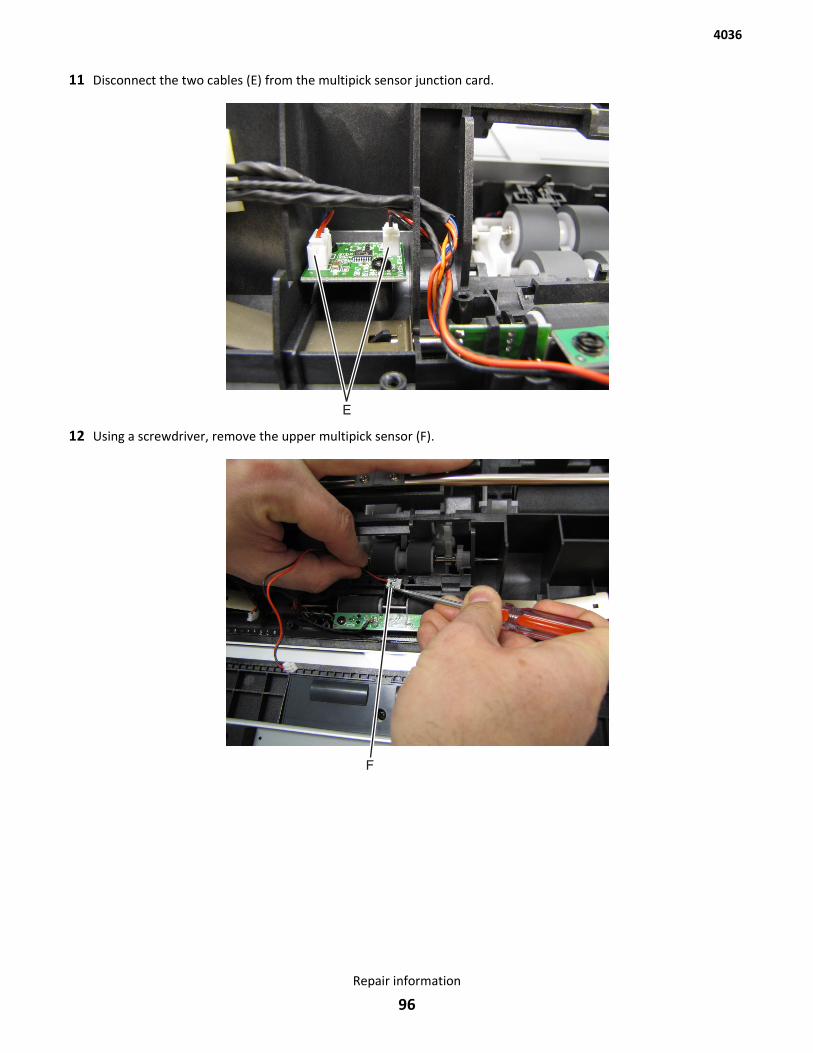
11 Disconnect the two cables (E) from the multipick sensor junction card.
12 Using a screwdriver, remove the upper multipick sensor (F).
4036
Repair information
96
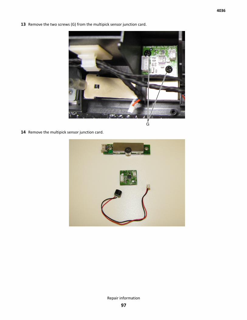
13 Remove the two screws (G) from the multipick sensor junction card.
14 Remove the multipick sensor junction card.
4036
Repair information
97
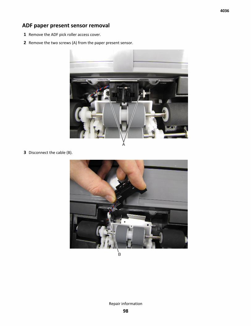
ADF paper present sensor removal1 Remove the ADF pick roller access cover.
2 Remove the two screws (A) from the paper present sensor.
3 Disconnect the cable (B).
4036
Repair information
98
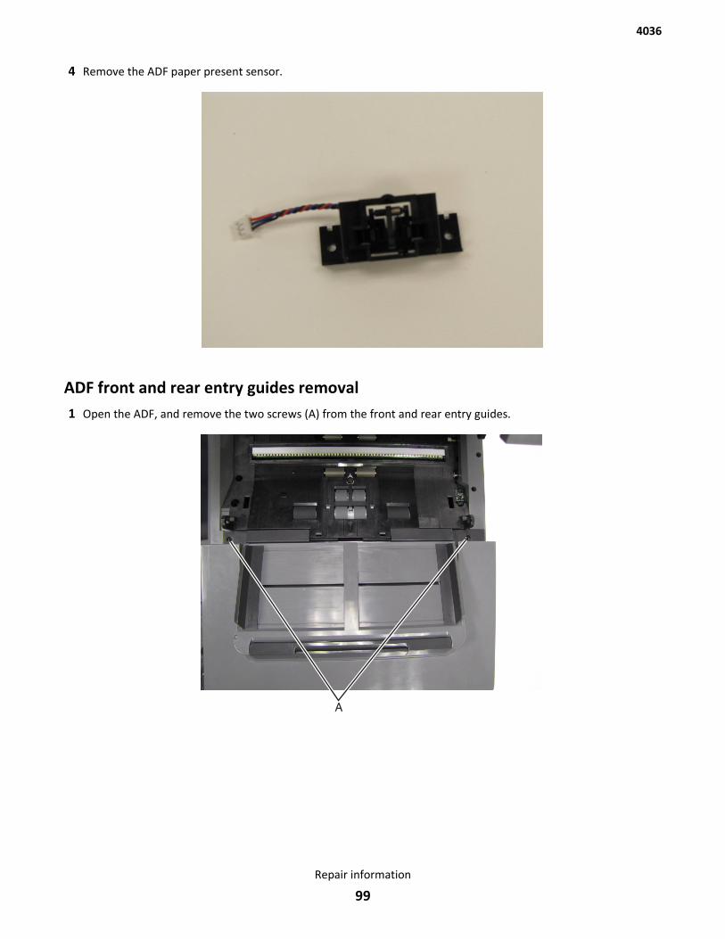
4 Remove the ADF paper present sensor.
ADF front and rear entry guides removal1 Open the ADF, and remove the two screws (A) from the front and rear entry guides.
4036
Repair information
99
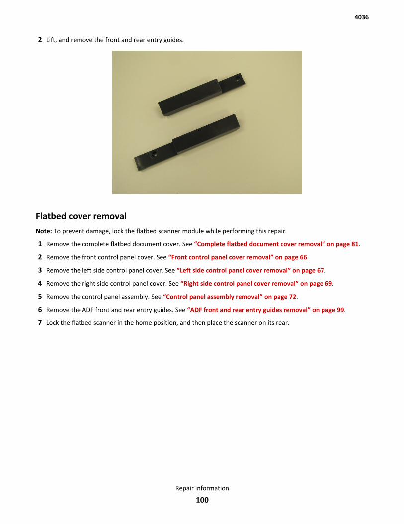
2 Lift, and remove the front and rear entry guides.
Flatbed cover removalNote: To prevent damage, lock the flatbed scanner module while performing this repair.
1 Remove the complete flatbed document cover. See “Complete flatbed document cover removal” on page 81.
2 Remove the front control panel cover. See “Front control panel cover removal” on page 66.
3 Remove the left side control panel cover. See “Left side control panel cover removal” on page 67.
4 Remove the right side control panel cover. See “Right side control panel cover removal” on page 69.
5 Remove the control panel assembly. See “Control panel assembly removal” on page 72.
6 Remove the ADF front and rear entry guides. See “ADF front and rear entry guides removal” on page 99.
7 Lock the flatbed scanner in the home position, and then place the scanner on its rear.
4036
Repair information
100
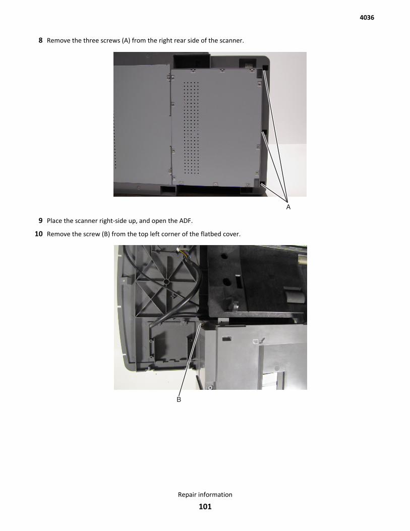
8 Remove the three screws (A) from the right rear side of the scanner.
9 Place the scanner right-side up, and open the ADF.
10 Remove the screw (B) from the top left corner of the flatbed cover.
4036
Repair information
101
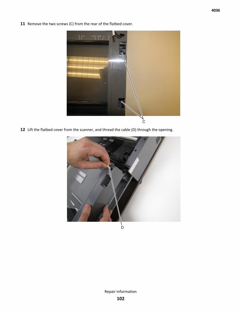
11 Remove the two screws (C) from the rear of the flatbed cover.
12 Lift the flatbed cover from the scanner, and thread the cable (D) through the opening.
4036
Repair information
102
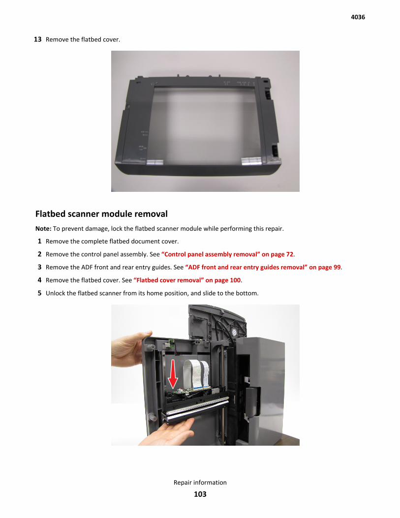
13 Remove the flatbed cover.
Flatbed scanner module removalNote: To prevent damage, lock the flatbed scanner module while performing this repair.
1 Remove the complete flatbed document cover.
2 Remove the control panel assembly. See “Control panel assembly removal” on page 72.
3 Remove the ADF front and rear entry guides. See “ADF front and rear entry guides removal” on page 99.
4 Remove the flatbed cover. See “Flatbed cover removal” on page 100.
5 Unlock the flatbed scanner from its home position, and slide to the bottom.
4036
Repair information
103
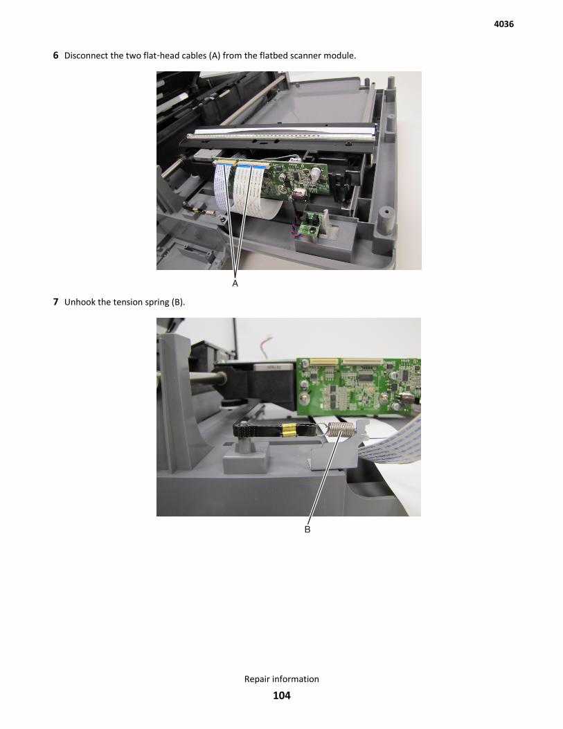
6 Disconnect the two flat‑head cables (A) from the flatbed scanner module.
7 Unhook the tension spring (B).
4036
Repair information
104
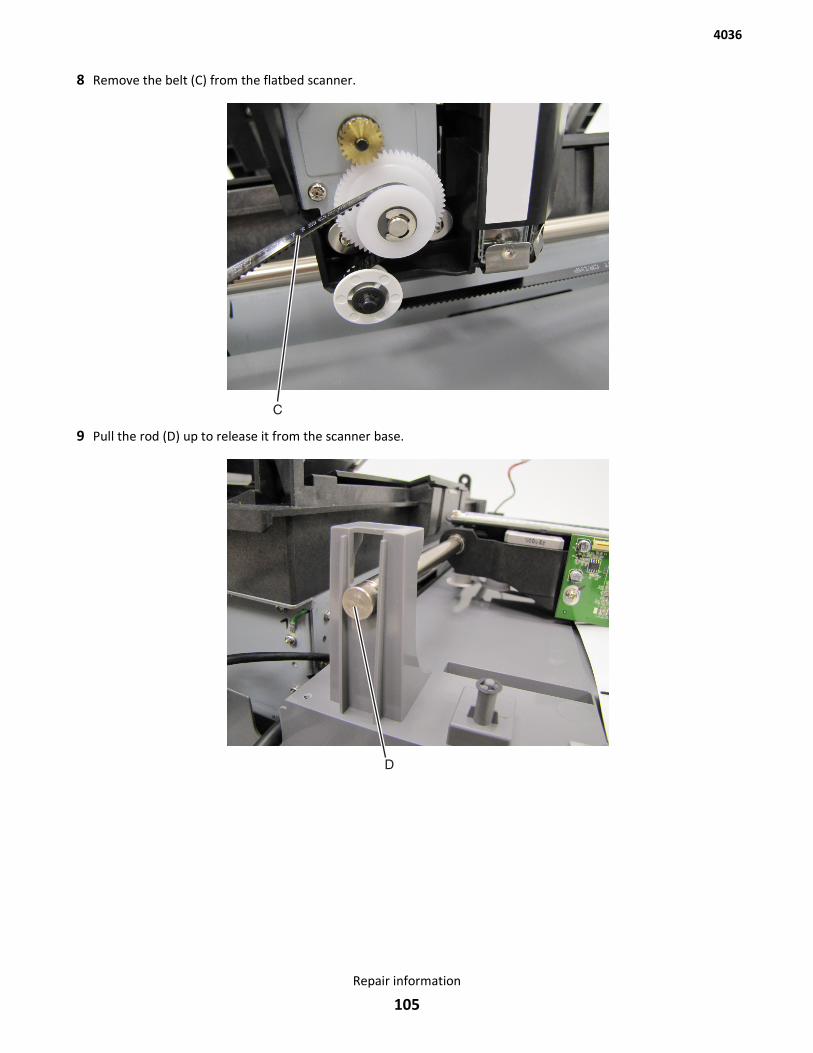
8 Remove the belt (C) from the flatbed scanner.
9 Pull the rod (D) up to release it from the scanner base.
4036
Repair information
105
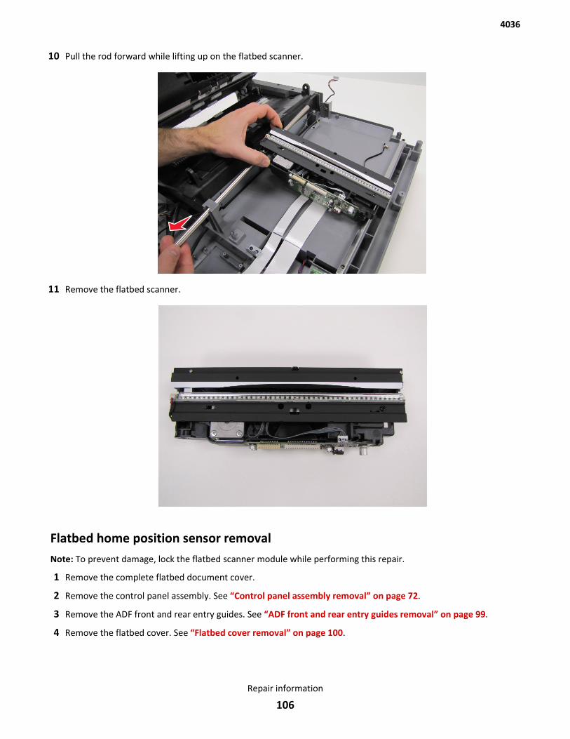
10 Pull the rod forward while lifting up on the flatbed scanner.
11 Remove the flatbed scanner.
Flatbed home position sensor removalNote: To prevent damage, lock the flatbed scanner module while performing this repair.
1 Remove the complete flatbed document cover.
2 Remove the control panel assembly. See “Control panel assembly removal” on page 72.
3 Remove the ADF front and rear entry guides. See “ADF front and rear entry guides removal” on page 99.
4 Remove the flatbed cover. See “Flatbed cover removal” on page 100.
4036
Repair information
106

5 Unlock the flatbed scanner from its home position, and slide to the bottom.
6 Place the scanner up on its rear, and remove the thirteen screws (A) from the controller access cover.
7 Remove the four screws (B) from the engine access cover.
CAUTION—SHOCK HAZARD:
4036
Repair information
107
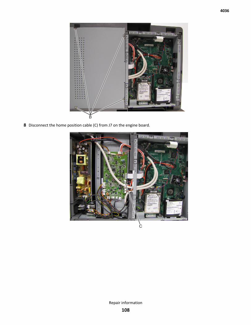
8 Disconnect the home position cable (C) from J7 on the engine board.
4036
Repair information
108
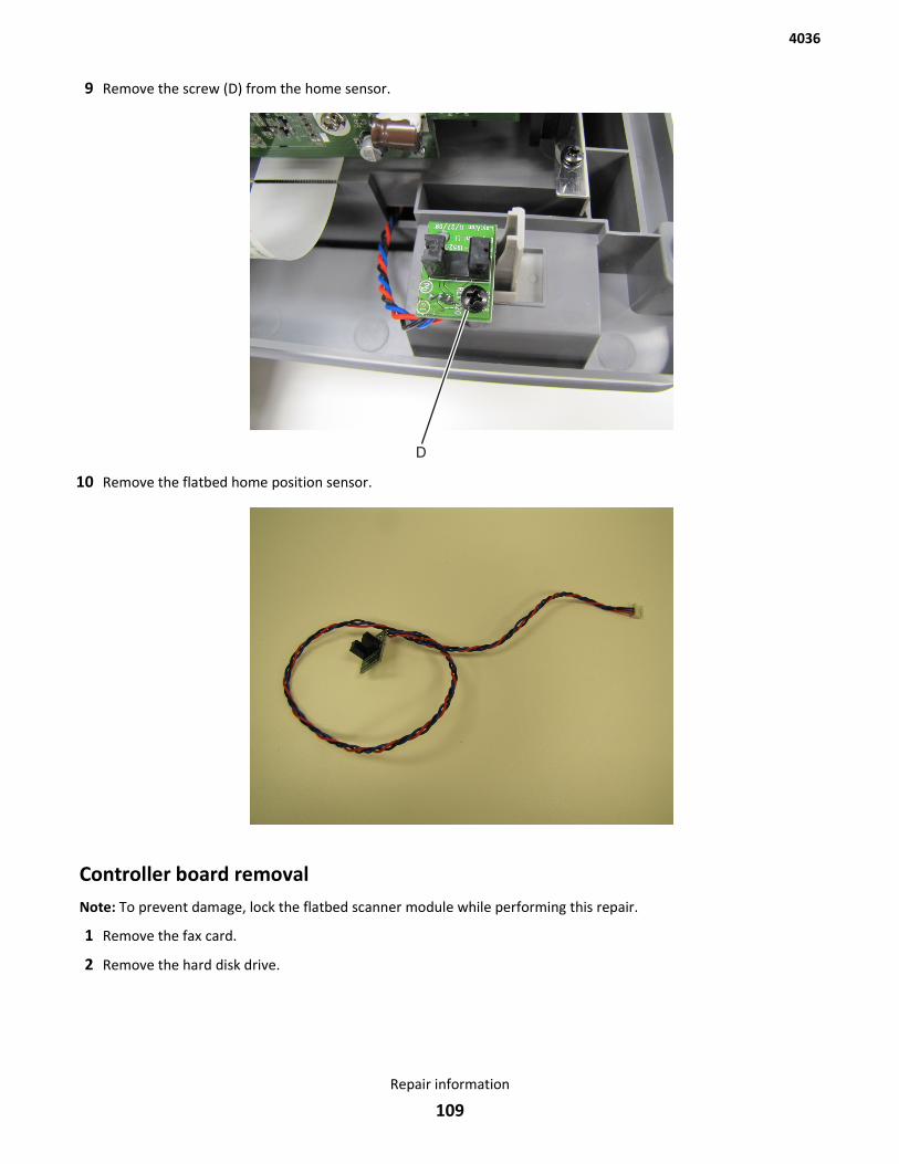
9 Remove the screw (D) from the home sensor.
10 Remove the flatbed home position sensor.
Controller board removalNote: To prevent damage, lock the flatbed scanner module while performing this repair.
1 Remove the fax card.
2 Remove the hard disk drive.
4036
Repair information
109
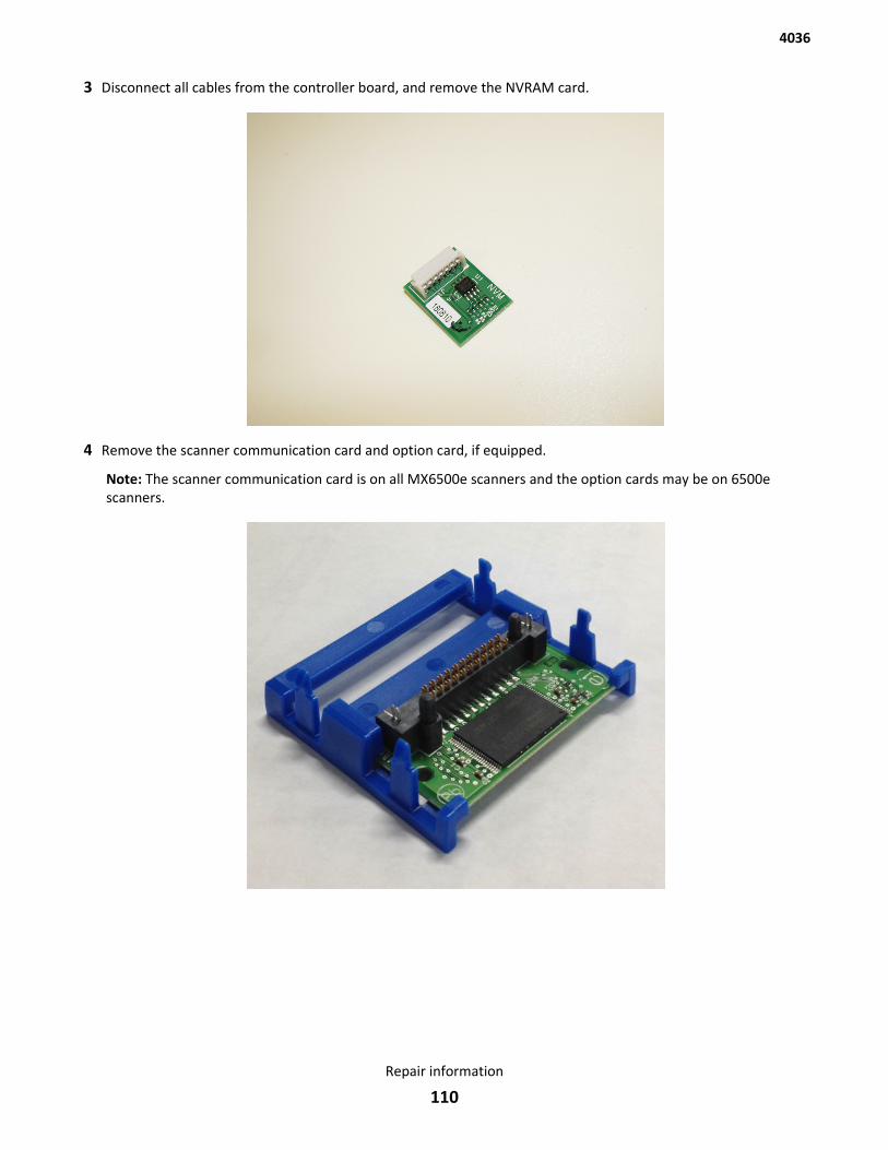
3 Disconnect all cables from the controller board, and remove the NVRAM card.
4 Remove the scanner communication card and option card, if equipped.
Note: The scanner communication card is on all MX6500e scanners and the option cards may be on 6500escanners.
4036
Repair information
110
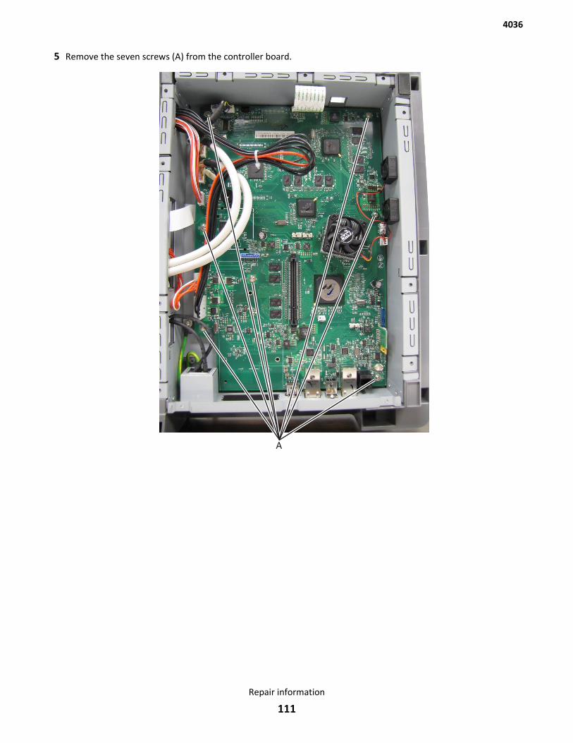
5 Remove the seven screws (A) from the controller board.
4036
Repair information
111
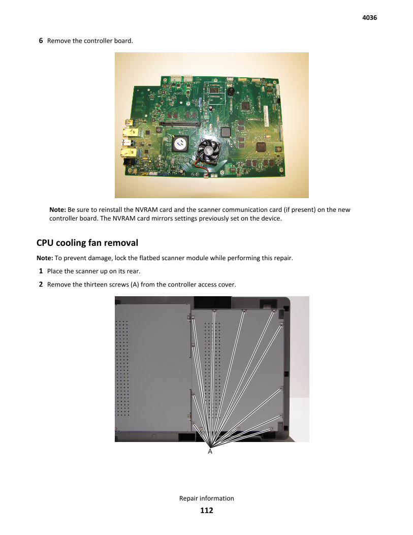
6 Remove the controller board.
Note: Be sure to reinstall the NVRAM card and the scanner communication card (if present) on the newcontroller board. The NVRAM card mirrors settings previously set on the device.
CPU cooling fan removalNote: To prevent damage, lock the flatbed scanner module while performing this repair.
1 Place the scanner up on its rear.
2 Remove the thirteen screws (A) from the controller access cover.
4036
Repair information
112
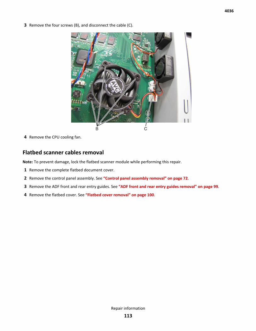
3 Remove the four screws (B), and disconnect the cable (C).
4 Remove the CPU cooling fan.
Flatbed scanner cables removalNote: To prevent damage, lock the flatbed scanner module while performing this repair.
1 Remove the complete flatbed document cover.
2 Remove the control panel assembly. See “Control panel assembly removal” on page 72.
3 Remove the ADF front and rear entry guides. See “ADF front and rear entry guides removal” on page 99.
4 Remove the flatbed cover. See “Flatbed cover removal” on page 100.
4036
Repair information
113
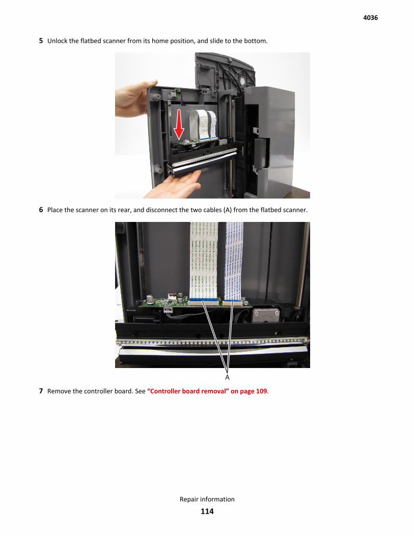
5 Unlock the flatbed scanner from its home position, and slide to the bottom.
6 Place the scanner on its rear, and disconnect the two cables (A) from the flatbed scanner.
7 Remove the controller board. See “Controller board removal” on page 109.
4036
Repair information
114
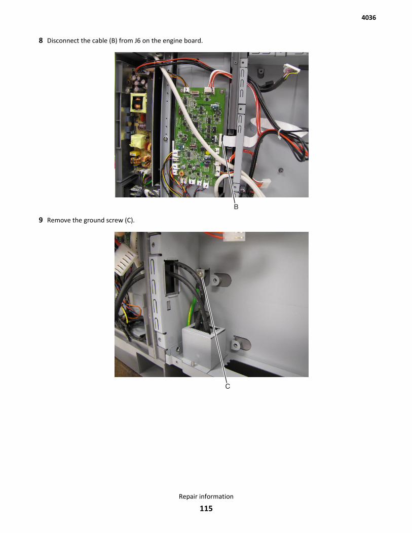
8 Disconnect the cable (B) from J6 on the engine board.
9 Remove the ground screw (C).
4036
Repair information
115
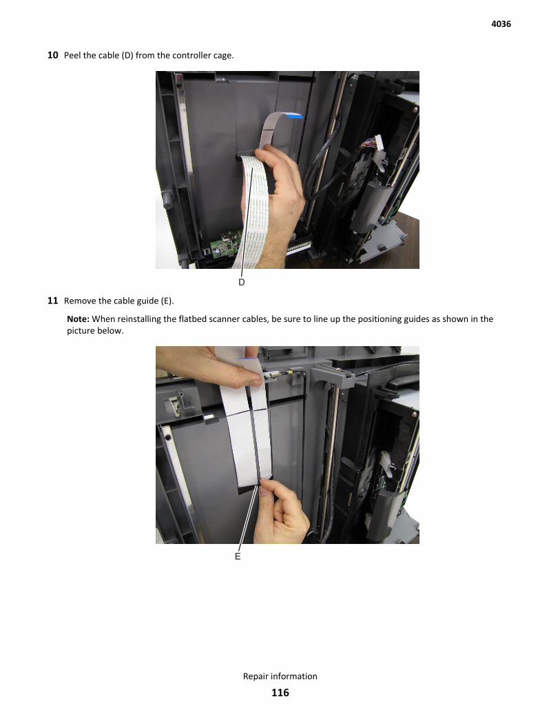
10 Peel the cable (D) from the controller cage.
11 Remove the cable guide (E).
Note: When reinstalling the flatbed scanner cables, be sure to line up the positioning guides as shown in thepicture below.
4036
Repair information
116
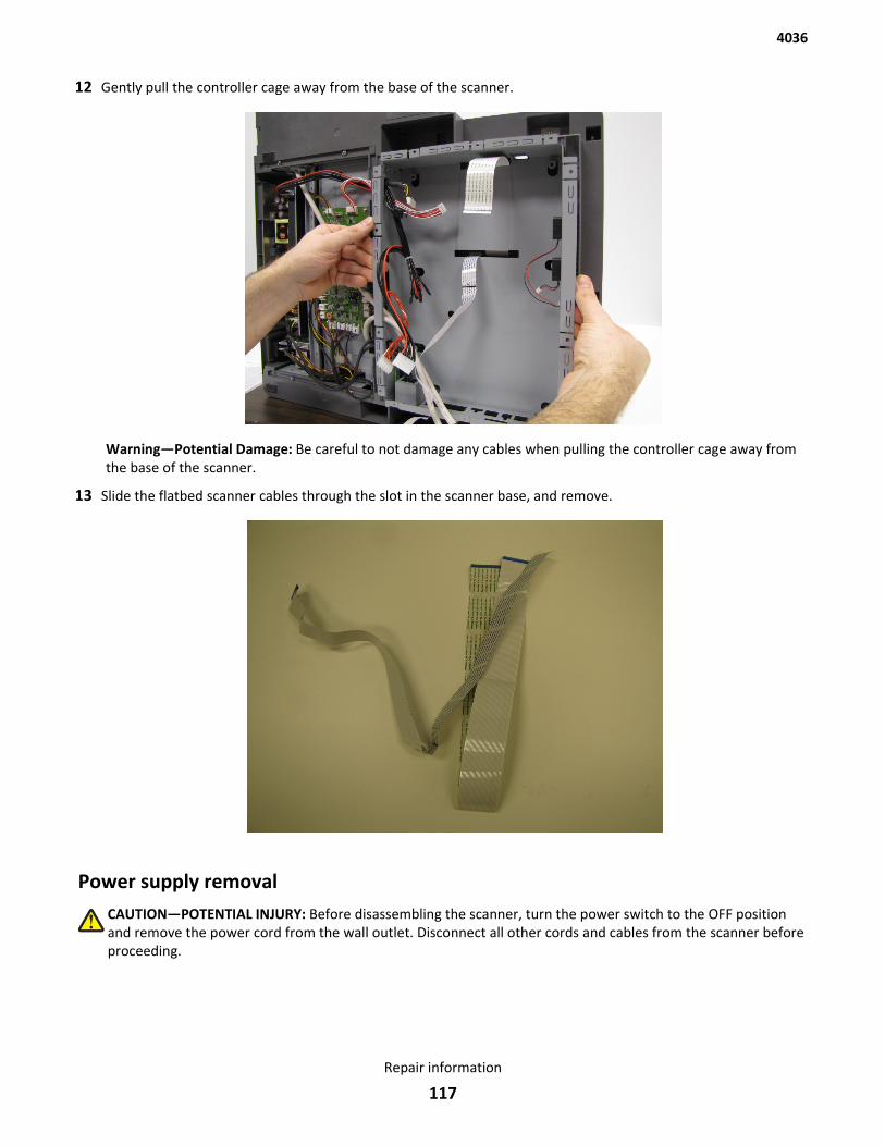
12 Gently pull the controller cage away from the base of the scanner.
Warning—Potential Damage: Be careful to not damage any cables when pulling the controller cage away fromthe base of the scanner.
13 Slide the flatbed scanner cables through the slot in the scanner base, and remove.
Power supply removalCAUTION—POTENTIAL INJURY: Before disassembling the scanner, turn the power switch to the OFF positionand remove the power cord from the wall outlet. Disconnect all other cords and cables from the scanner beforeproceeding.
4036
Repair information
117
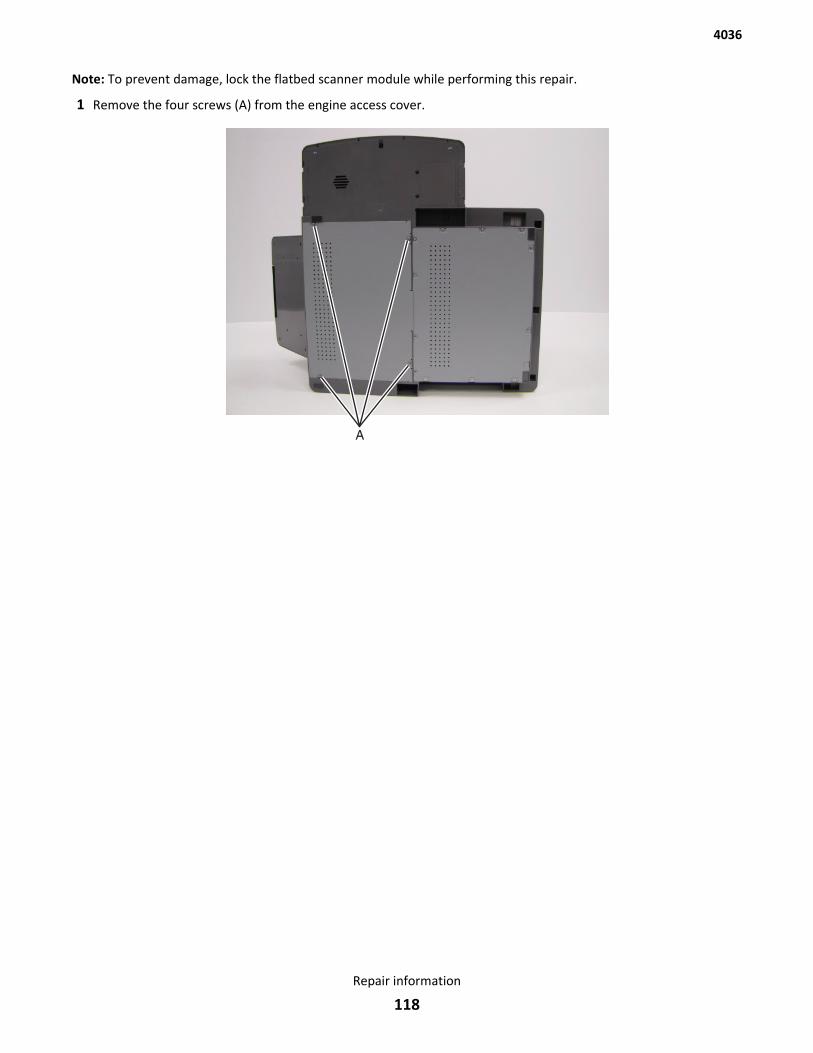
Note: To prevent damage, lock the flatbed scanner module while performing this repair.
1 Remove the four screws (A) from the engine access cover.
4036
Repair information
118
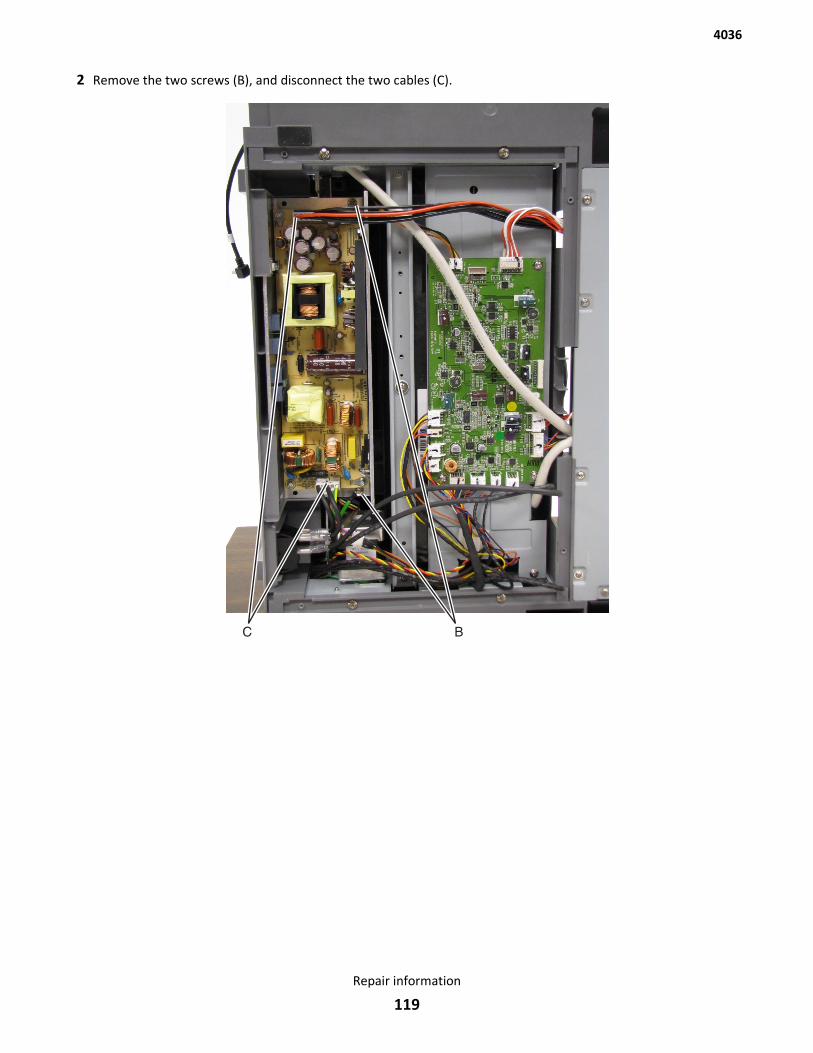
2 Remove the two screws (B), and disconnect the two cables (C).
4036
Repair information
119
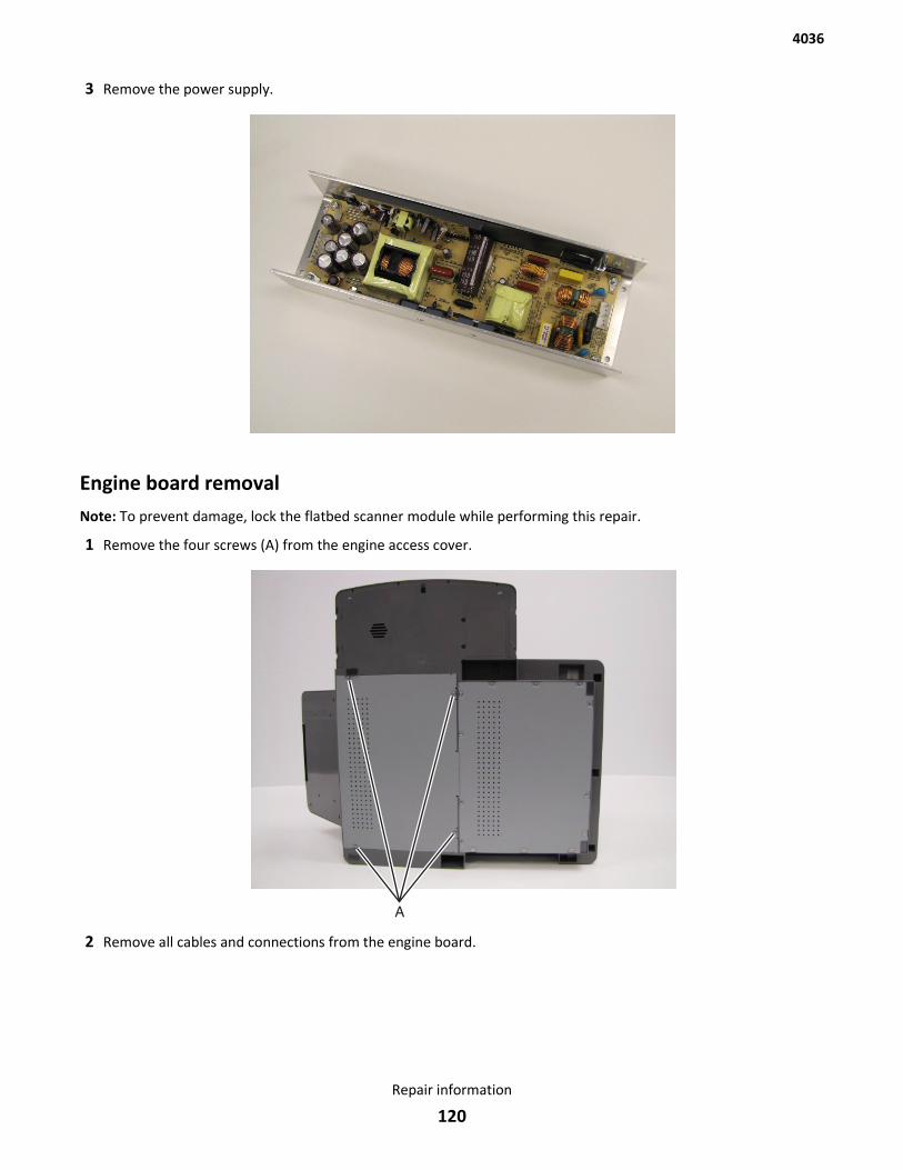
3 Remove the power supply.
Engine board removalNote: To prevent damage, lock the flatbed scanner module while performing this repair.
1 Remove the four screws (A) from the engine access cover.
2 Remove all cables and connections from the engine board.
4036
Repair information
120
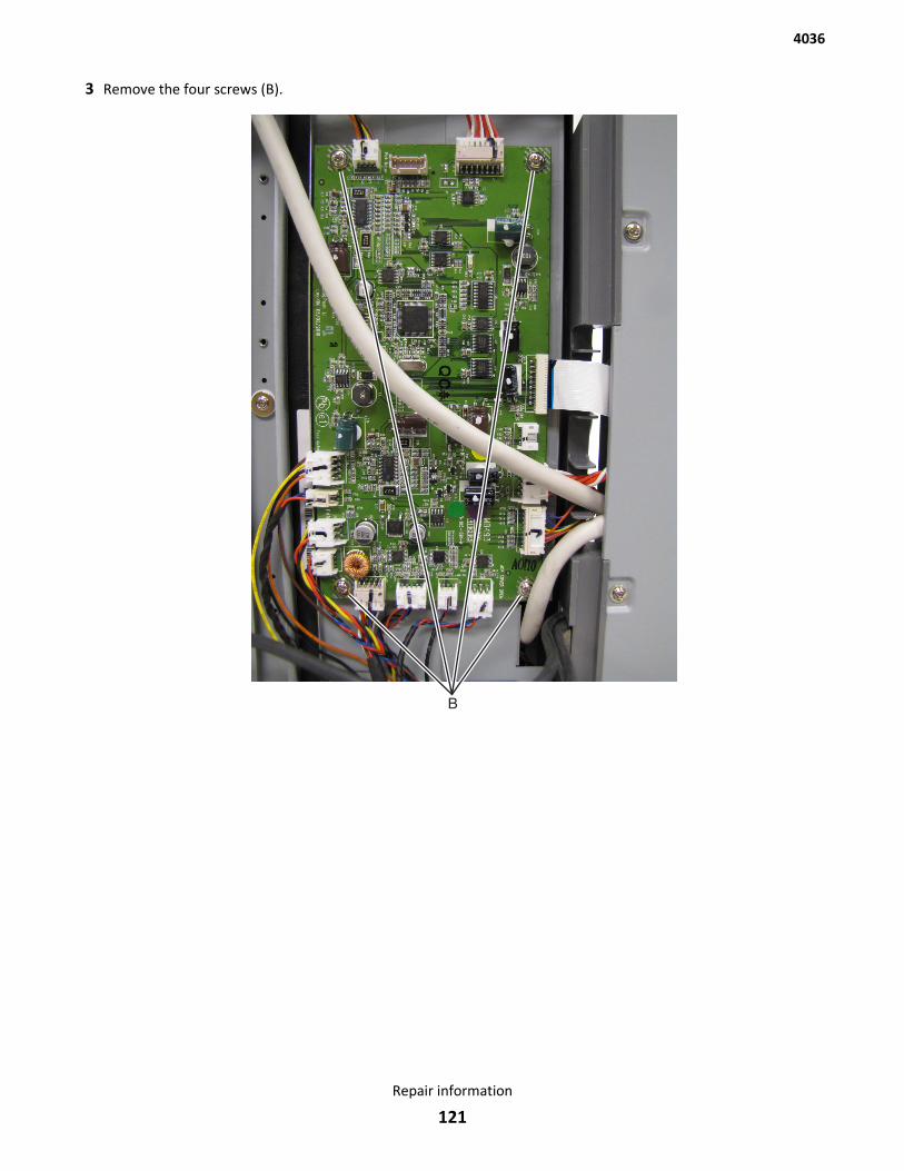
3 Remove the four screws (B).
4036
Repair information
121
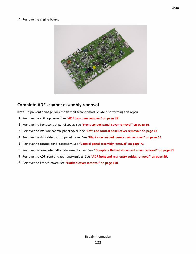
4 Remove the engine board.
Complete ADF scanner assembly removalNote: To prevent damage, lock the flatbed scanner module while performing this repair.
1 Remove the ADF top cover. See “ADF top cover removal” on page 85.
2 Remove the front control panel cover. See “Front control panel cover removal” on page 66.
3 Remove the left side control panel cover. See “Left side control panel cover removal” on page 67.
4 Remove the right side control panel cover. See “Right side control panel cover removal” on page 69.
5 Remove the control panel assembly. See “Control panel assembly removal” on page 72.
6 Remove the complete flatbed document cover. See “Complete flatbed document cover removal” on page 81.
7 Remove the ADF front and rear entry guides. See “ADF front and rear entry guides removal” on page 99.
8 Remove the flatbed cover. See “Flatbed cover removal” on page 100.
4036
Repair information
122
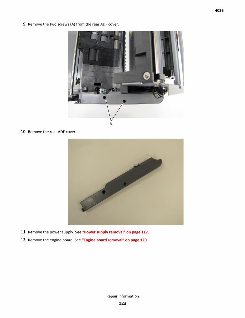
9 Remove the two screws (A) from the rear ADF cover.
10 Remove the rear ADF cover.
11 Remove the power supply. See “Power supply removal” on page 117.
12 Remove the engine board. See “Engine board removal” on page 120.
4036
Repair information
123
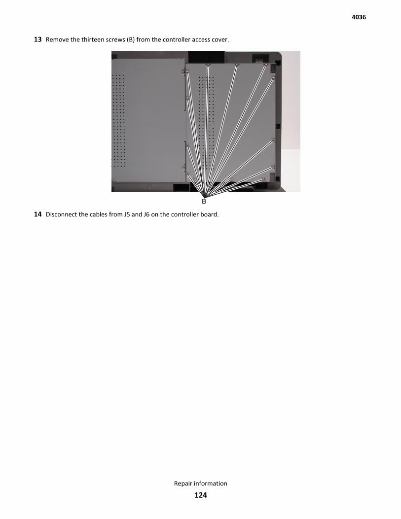
13 Remove the thirteen screws (B) from the controller access cover.
14 Disconnect the cables from J5 and J6 on the controller board.
4036
Repair information
124
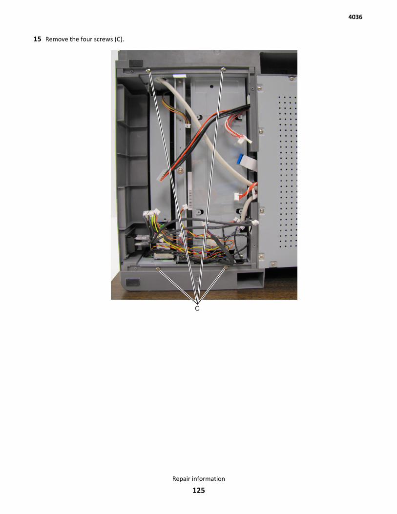
15 Remove the four screws (C).
4036
Repair information
125
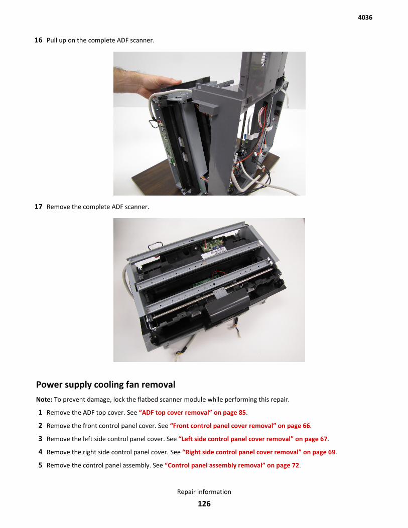
16 Pull up on the complete ADF scanner.
17 Remove the complete ADF scanner.
Power supply cooling fan removalNote: To prevent damage, lock the flatbed scanner module while performing this repair.
1 Remove the ADF top cover. See “ADF top cover removal” on page 85.
2 Remove the front control panel cover. See “Front control panel cover removal” on page 66.
3 Remove the left side control panel cover. See “Left side control panel cover removal” on page 67.
4 Remove the right side control panel cover. See “Right side control panel cover removal” on page 69.
5 Remove the control panel assembly. See “Control panel assembly removal” on page 72.
4036
Repair information
126
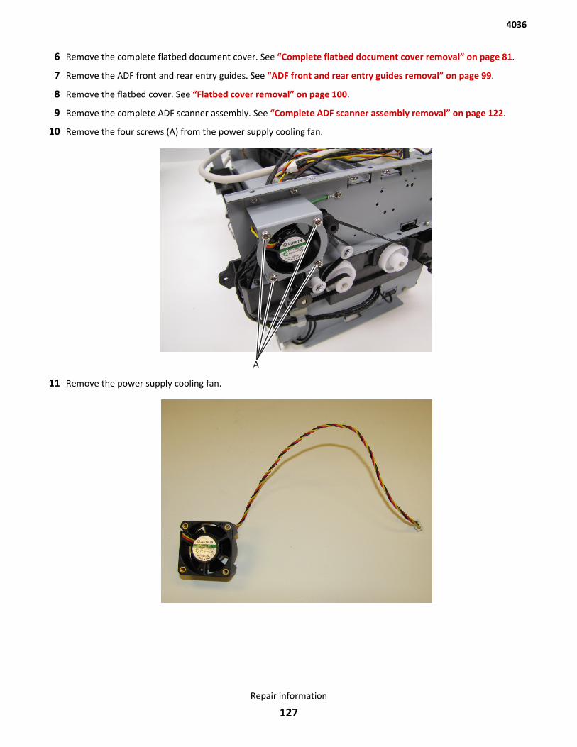
6 Remove the complete flatbed document cover. See “Complete flatbed document cover removal” on page 81.
7 Remove the ADF front and rear entry guides. See “ADF front and rear entry guides removal” on page 99.
8 Remove the flatbed cover. See “Flatbed cover removal” on page 100.
9 Remove the complete ADF scanner assembly. See “Complete ADF scanner assembly removal” on page 122.
10 Remove the four screws (A) from the power supply cooling fan.
11 Remove the power supply cooling fan.
4036
Repair information
127
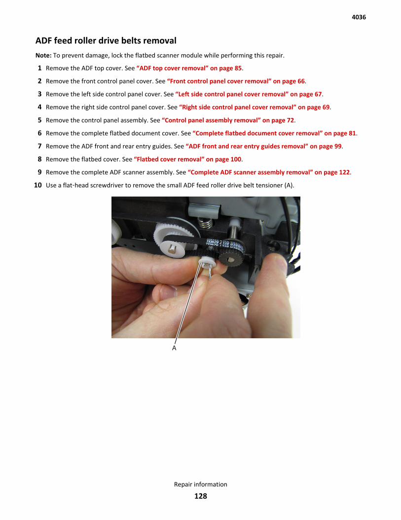
ADF feed roller drive belts removalNote: To prevent damage, lock the flatbed scanner module while performing this repair.
1 Remove the ADF top cover. See “ADF top cover removal” on page 85.
2 Remove the front control panel cover. See “Front control panel cover removal” on page 66.
3 Remove the left side control panel cover. See “Left side control panel cover removal” on page 67.
4 Remove the right side control panel cover. See “Right side control panel cover removal” on page 69.
5 Remove the control panel assembly. See “Control panel assembly removal” on page 72.
6 Remove the complete flatbed document cover. See “Complete flatbed document cover removal” on page 81.
7 Remove the ADF front and rear entry guides. See “ADF front and rear entry guides removal” on page 99.
8 Remove the flatbed cover. See “Flatbed cover removal” on page 100.
9 Remove the complete ADF scanner assembly. See “Complete ADF scanner assembly removal” on page 122.
10 Use a flat‑head screwdriver to remove the small ADF feed roller drive belt tensioner (A).
4036
Repair information
128
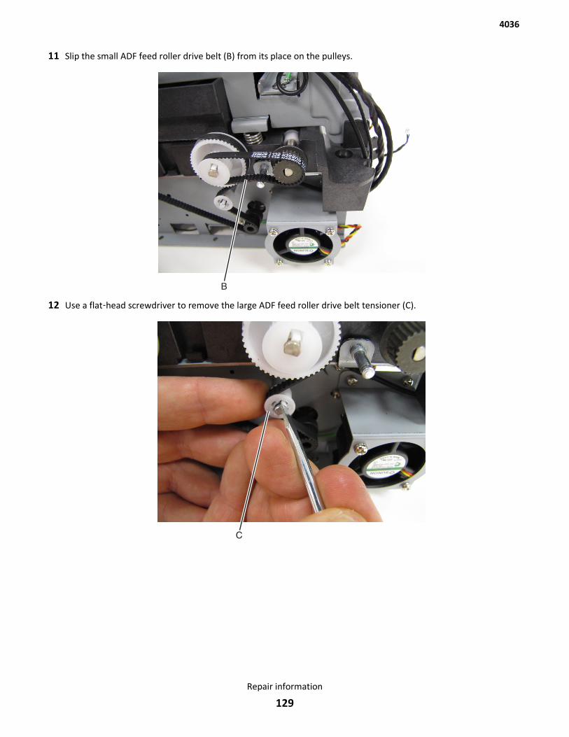
11 Slip the small ADF feed roller drive belt (B) from its place on the pulleys.
12 Use a flat‑head screwdriver to remove the large ADF feed roller drive belt tensioner (C).
4036
Repair information
129
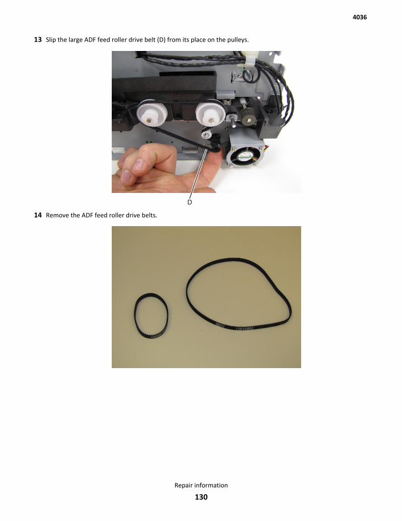
13 Slip the large ADF feed roller drive belt (D) from its place on the pulleys.
14 Remove the ADF feed roller drive belts.
4036
Repair information
130
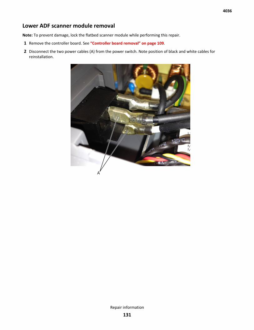
Lower ADF scanner module removalNote: To prevent damage, lock the flatbed scanner module while performing this repair.
1 Remove the controller board. See “Controller board removal” on page 109.
2 Disconnect the two power cables (A) from the power switch. Note position of black and white cables forreinstallation.
A
4036
Repair information
131
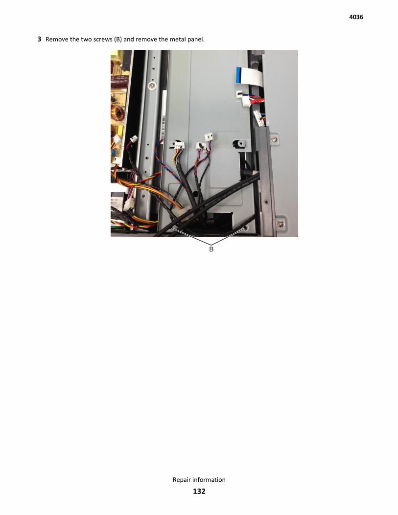
3 Remove the two screws (B) and remove the metal panel.
B
4036
Repair information
132
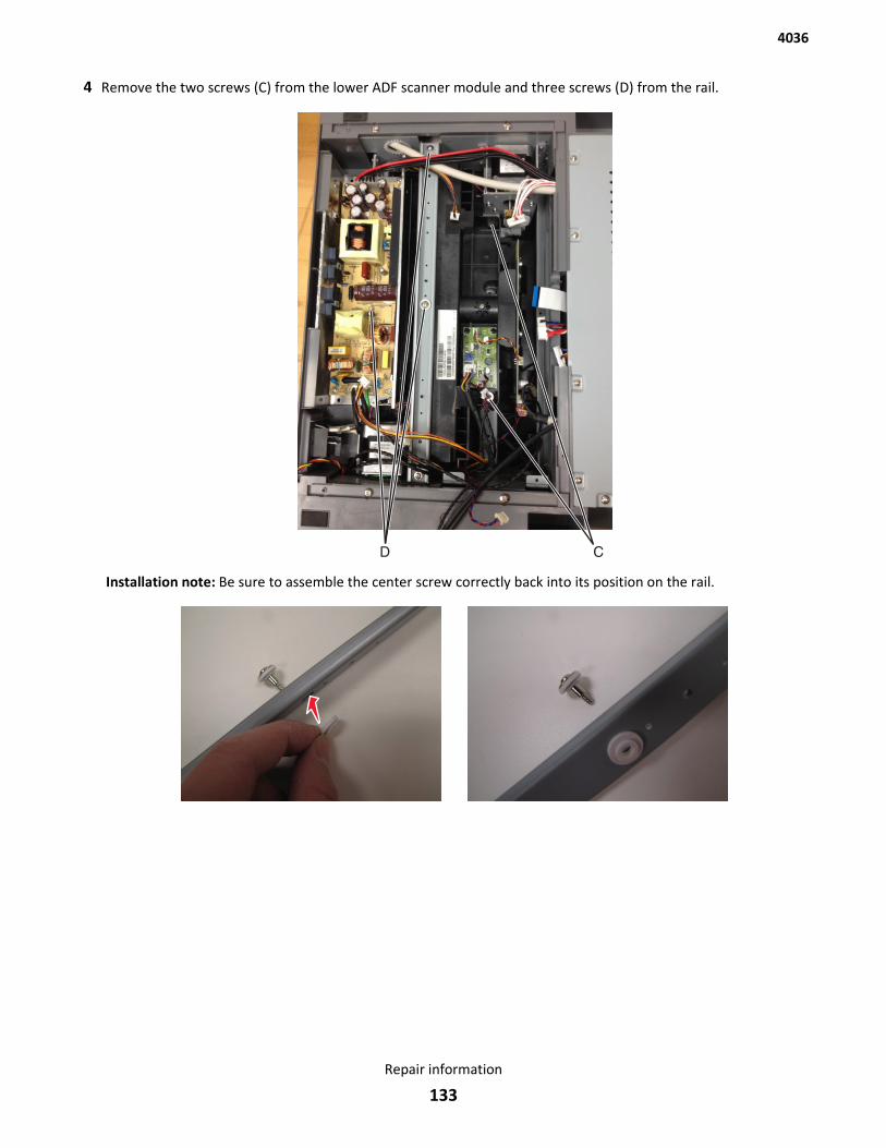
4 Remove the two screws (C) from the lower ADF scanner module and three screws (D) from the rail.
CD
Installation note: Be sure to assemble the center screw correctly back into its position on the rail.
4036
Repair information
133
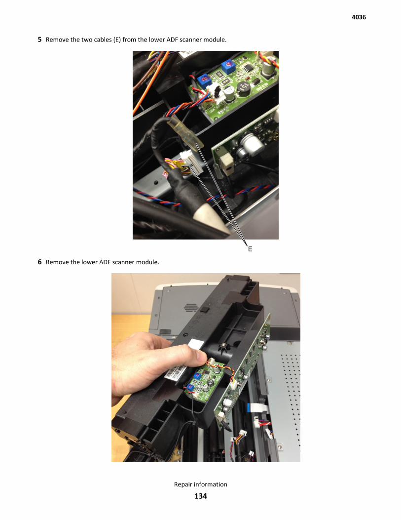
5 Remove the two cables (E) from the lower ADF scanner module.
E
6 Remove the lower ADF scanner module.
4036
Repair information
134
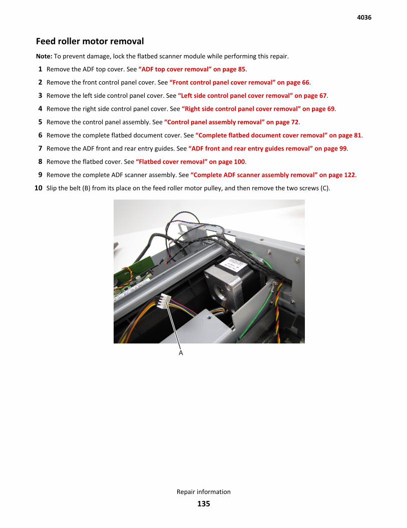
Feed roller motor removalNote: To prevent damage, lock the flatbed scanner module while performing this repair.
1 Remove the ADF top cover. See “ADF top cover removal” on page 85.
2 Remove the front control panel cover. See “Front control panel cover removal” on page 66.
3 Remove the left side control panel cover. See “Left side control panel cover removal” on page 67.
4 Remove the right side control panel cover. See “Right side control panel cover removal” on page 69.
5 Remove the control panel assembly. See “Control panel assembly removal” on page 72.
6 Remove the complete flatbed document cover. See “Complete flatbed document cover removal” on page 81.
7 Remove the ADF front and rear entry guides. See “ADF front and rear entry guides removal” on page 99.
8 Remove the flatbed cover. See “Flatbed cover removal” on page 100.
9 Remove the complete ADF scanner assembly. See “Complete ADF scanner assembly removal” on page 122.
10 Slip the belt (B) from its place on the feed roller motor pulley, and then remove the two screws (C).
4036
Repair information
135
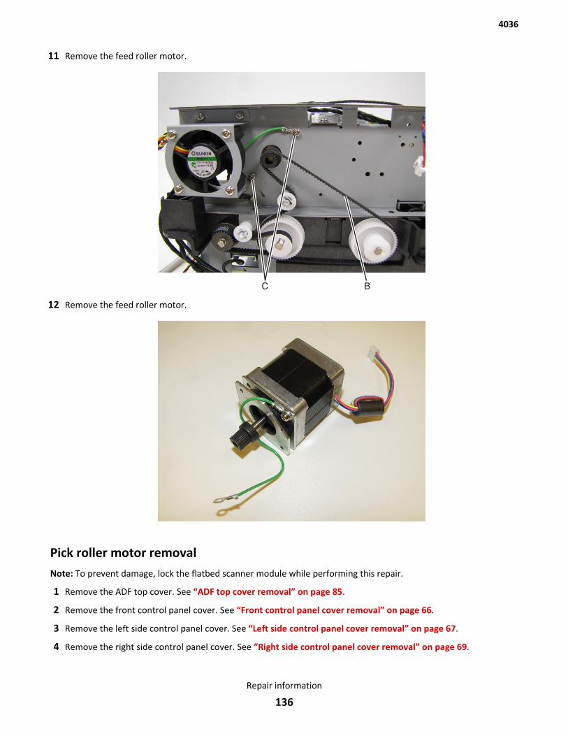
11 Remove the feed roller motor.
12 Remove the feed roller motor.
Pick roller motor removalNote: To prevent damage, lock the flatbed scanner module while performing this repair.
1 Remove the ADF top cover. See “ADF top cover removal” on page 85.
2 Remove the front control panel cover. See “Front control panel cover removal” on page 66.
3 Remove the left side control panel cover. See “Left side control panel cover removal” on page 67.
4 Remove the right side control panel cover. See “Right side control panel cover removal” on page 69.
4036
Repair information
136
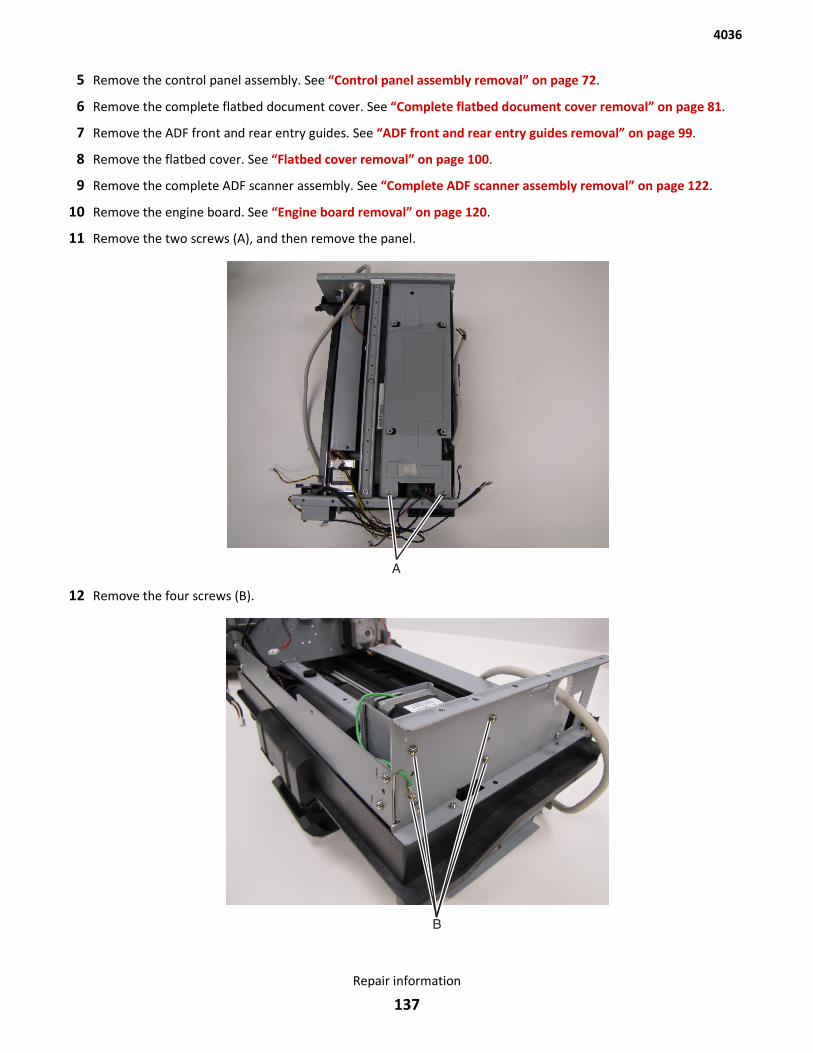
5 Remove the control panel assembly. See “Control panel assembly removal” on page 72.
6 Remove the complete flatbed document cover. See “Complete flatbed document cover removal” on page 81.
7 Remove the ADF front and rear entry guides. See “ADF front and rear entry guides removal” on page 99.
8 Remove the flatbed cover. See “Flatbed cover removal” on page 100.
9 Remove the complete ADF scanner assembly. See “Complete ADF scanner assembly removal” on page 122.
10 Remove the engine board. See “Engine board removal” on page 120.
11 Remove the two screws (A), and then remove the panel.
12 Remove the four screws (B).
4036
Repair information
137
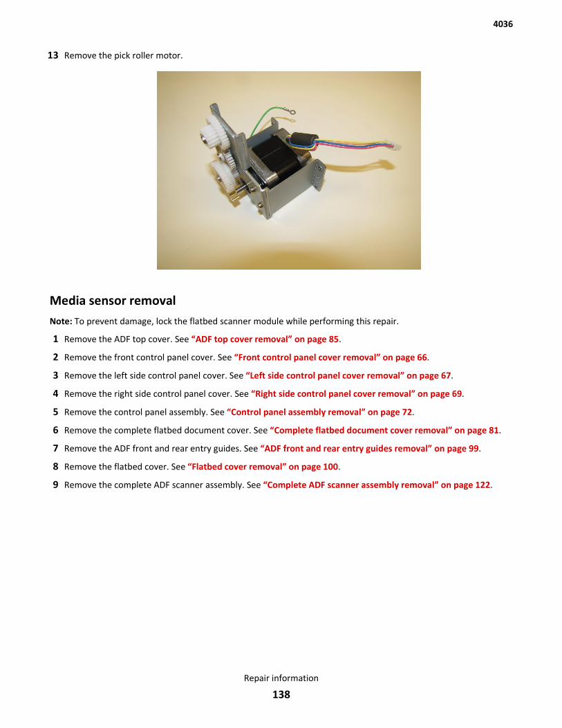
13 Remove the pick roller motor.
Media sensor removalNote: To prevent damage, lock the flatbed scanner module while performing this repair.
1 Remove the ADF top cover. See “ADF top cover removal” on page 85.
2 Remove the front control panel cover. See “Front control panel cover removal” on page 66.
3 Remove the left side control panel cover. See “Left side control panel cover removal” on page 67.
4 Remove the right side control panel cover. See “Right side control panel cover removal” on page 69.
5 Remove the control panel assembly. See “Control panel assembly removal” on page 72.
6 Remove the complete flatbed document cover. See “Complete flatbed document cover removal” on page 81.
7 Remove the ADF front and rear entry guides. See “ADF front and rear entry guides removal” on page 99.
8 Remove the flatbed cover. See “Flatbed cover removal” on page 100.
9 Remove the complete ADF scanner assembly. See “Complete ADF scanner assembly removal” on page 122.
4036
Repair information
138
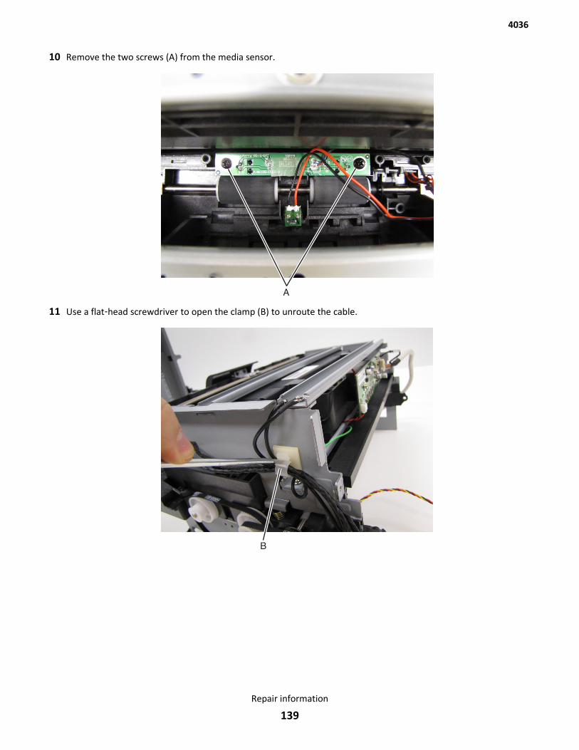
10 Remove the two screws (A) from the media sensor.
11 Use a flat‑head screwdriver to open the clamp (B) to unroute the cable.
4036
Repair information
139
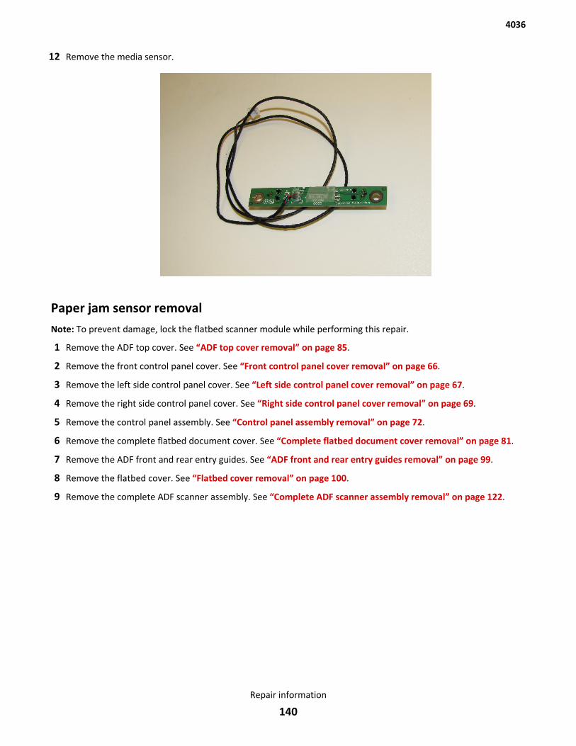
12 Remove the media sensor.
Paper jam sensor removalNote: To prevent damage, lock the flatbed scanner module while performing this repair.
1 Remove the ADF top cover. See “ADF top cover removal” on page 85.
2 Remove the front control panel cover. See “Front control panel cover removal” on page 66.
3 Remove the left side control panel cover. See “Left side control panel cover removal” on page 67.
4 Remove the right side control panel cover. See “Right side control panel cover removal” on page 69.
5 Remove the control panel assembly. See “Control panel assembly removal” on page 72.
6 Remove the complete flatbed document cover. See “Complete flatbed document cover removal” on page 81.
7 Remove the ADF front and rear entry guides. See “ADF front and rear entry guides removal” on page 99.
8 Remove the flatbed cover. See “Flatbed cover removal” on page 100.
9 Remove the complete ADF scanner assembly. See “Complete ADF scanner assembly removal” on page 122.
4036
Repair information
140
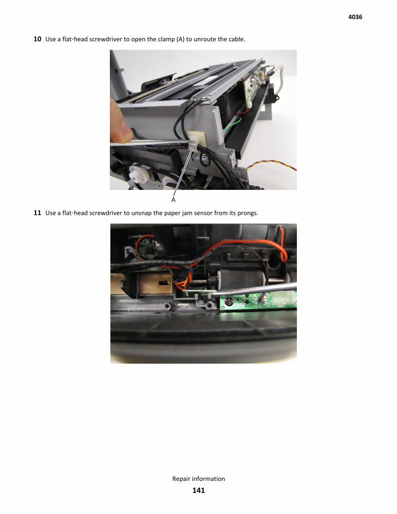
10 Use a flat‑head screwdriver to open the clamp (A) to unroute the cable.
11 Use a flat‑head screwdriver to unsnap the paper jam sensor from its prongs.
4036
Repair information
141
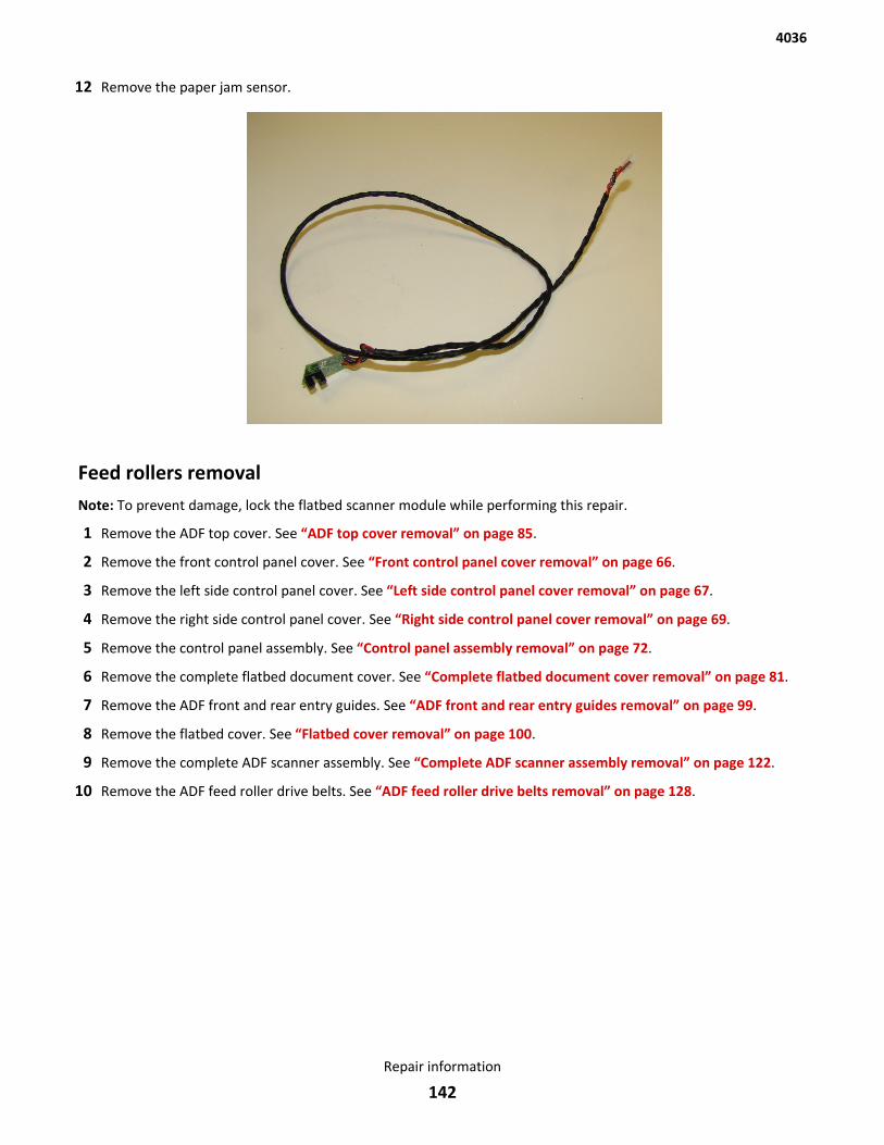
12 Remove the paper jam sensor.
Feed rollers removalNote: To prevent damage, lock the flatbed scanner module while performing this repair.
1 Remove the ADF top cover. See “ADF top cover removal” on page 85.
2 Remove the front control panel cover. See “Front control panel cover removal” on page 66.
3 Remove the left side control panel cover. See “Left side control panel cover removal” on page 67.
4 Remove the right side control panel cover. See “Right side control panel cover removal” on page 69.
5 Remove the control panel assembly. See “Control panel assembly removal” on page 72.
6 Remove the complete flatbed document cover. See “Complete flatbed document cover removal” on page 81.
7 Remove the ADF front and rear entry guides. See “ADF front and rear entry guides removal” on page 99.
8 Remove the flatbed cover. See “Flatbed cover removal” on page 100.
9 Remove the complete ADF scanner assembly. See “Complete ADF scanner assembly removal” on page 122.
10 Remove the ADF feed roller drive belts. See “ADF feed roller drive belts removal” on page 128.
4036
Repair information
142
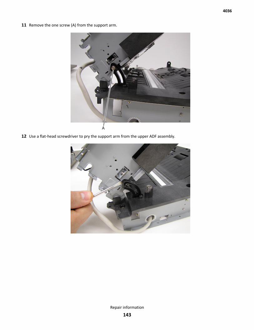
11 Remove the one screw (A) from the support arm.
12 Use a flat‑head screwdriver to pry the support arm from the upper ADF assembly.
4036
Repair information
143

13 Lift, and rotate the upper ADF assembly from the lower ADF assembly.
14 Remove the one screw (B).
4036
Repair information
144
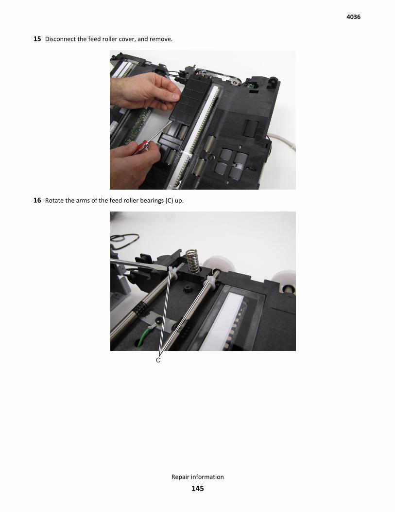
15 Disconnect the feed roller cover, and remove.
16 Rotate the arms of the feed roller bearings (C) up.
4036
Repair information
145
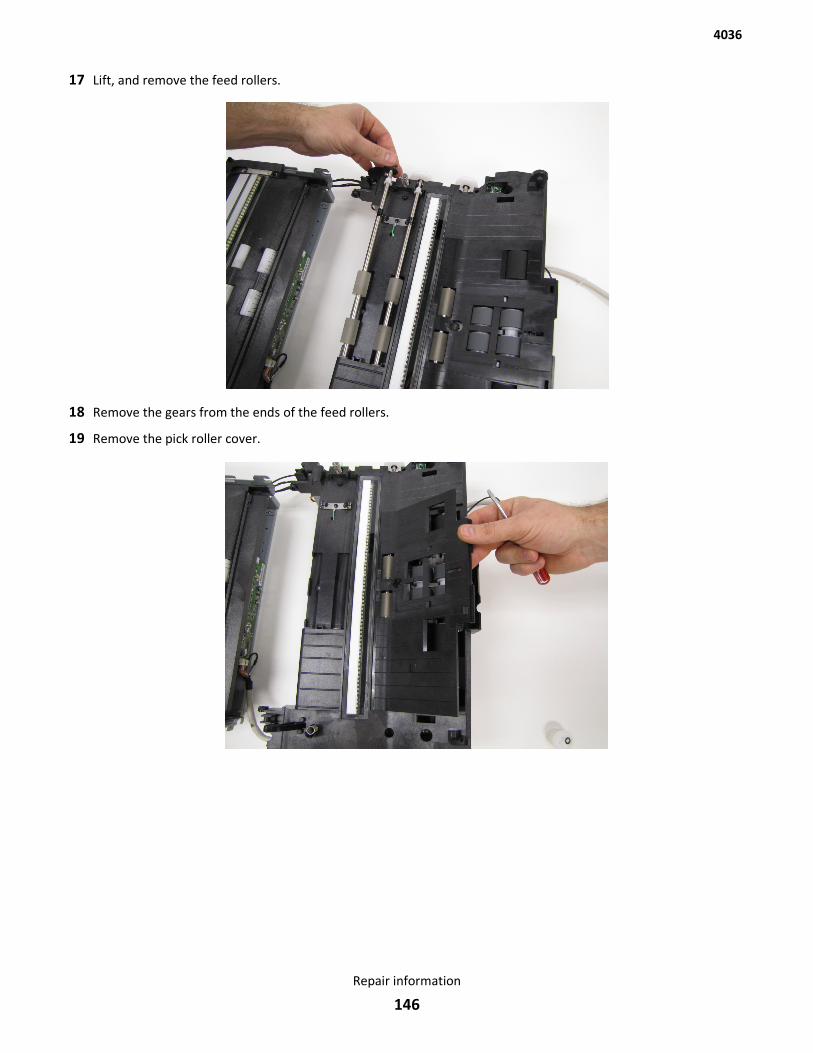
17 Lift, and remove the feed rollers.
18 Remove the gears from the ends of the feed rollers.
19 Remove the pick roller cover.
4036
Repair information
146
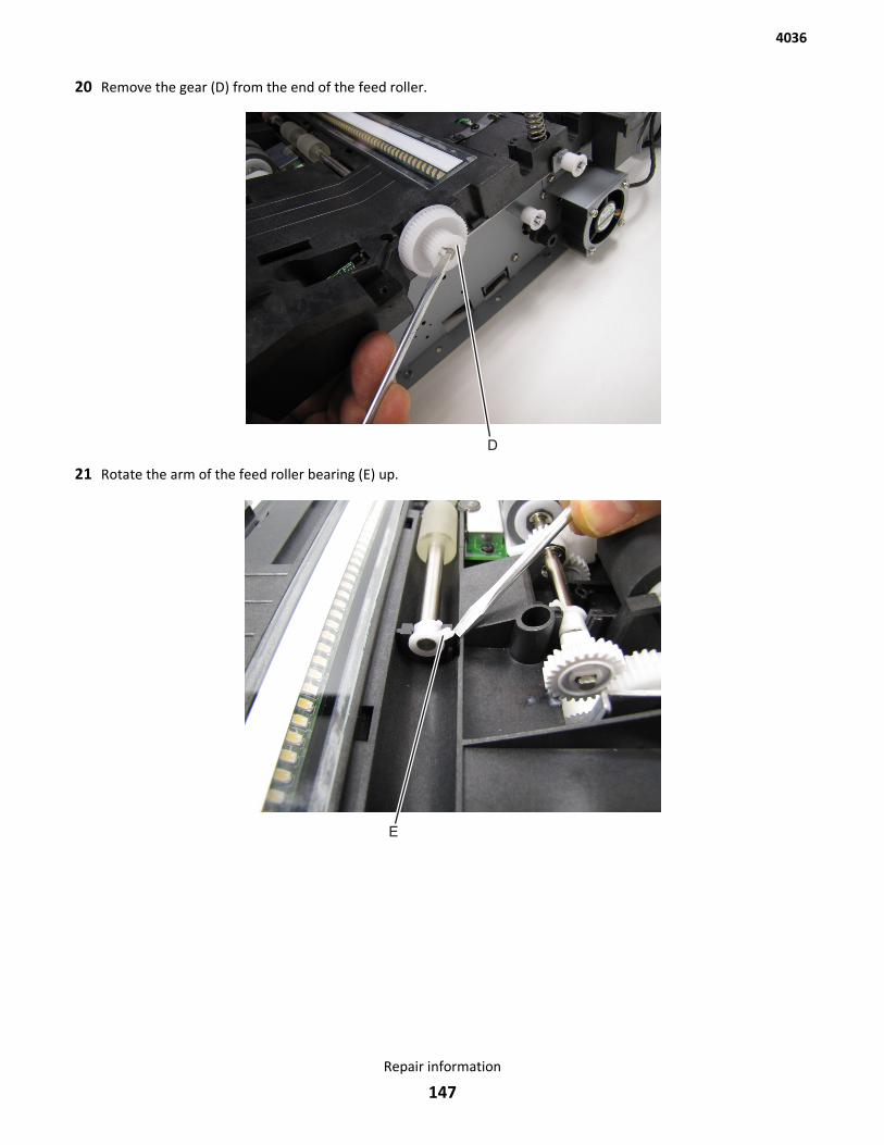
20 Remove the gear (D) from the end of the feed roller.
21 Rotate the arm of the feed roller bearing (E) up.
4036
Repair information
147
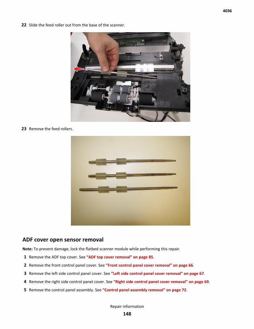
22 Slide the feed roller out from the base of the scanner.
23 Remove the feed rollers.
ADF cover open sensor removalNote: To prevent damage, lock the flatbed scanner module while performing this repair.
1 Remove the ADF top cover. See “ADF top cover removal” on page 85.
2 Remove the front control panel cover. See “Front control panel cover removal” on page 66.
3 Remove the left side control panel cover. See “Left side control panel cover removal” on page 67.
4 Remove the right side control panel cover. See “Right side control panel cover removal” on page 69.
5 Remove the control panel assembly. See “Control panel assembly removal” on page 72.
4036
Repair information
148
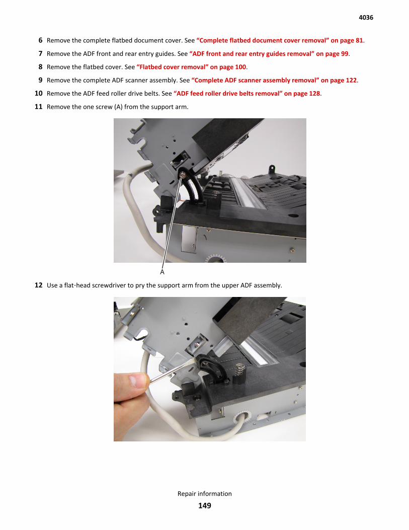
6 Remove the complete flatbed document cover. See “Complete flatbed document cover removal” on page 81.
7 Remove the ADF front and rear entry guides. See “ADF front and rear entry guides removal” on page 99.
8 Remove the flatbed cover. See “Flatbed cover removal” on page 100.
9 Remove the complete ADF scanner assembly. See “Complete ADF scanner assembly removal” on page 122.
10 Remove the ADF feed roller drive belts. See “ADF feed roller drive belts removal” on page 128.
11 Remove the one screw (A) from the support arm.
12 Use a flat‑head screwdriver to pry the support arm from the upper ADF assembly.
4036
Repair information
149
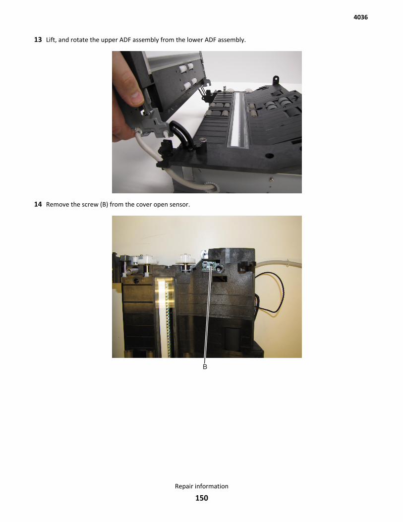
13 Lift, and rotate the upper ADF assembly from the lower ADF assembly.
14 Remove the screw (B) from the cover open sensor.
4036
Repair information
150
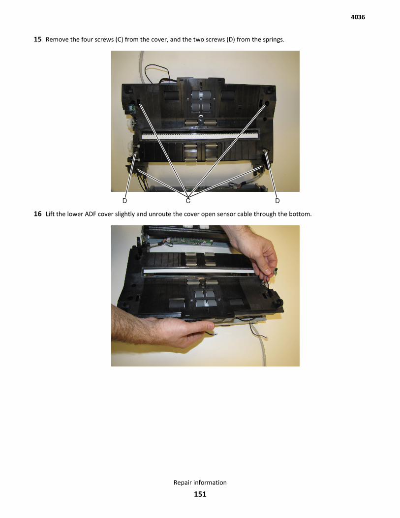
15 Remove the four screws (C) from the cover, and the two screws (D) from the springs.
16 Lift the lower ADF cover slightly and unroute the cover open sensor cable through the bottom.
4036
Repair information
151

17 Remove the cover open sensor.
4036
Repair information
152
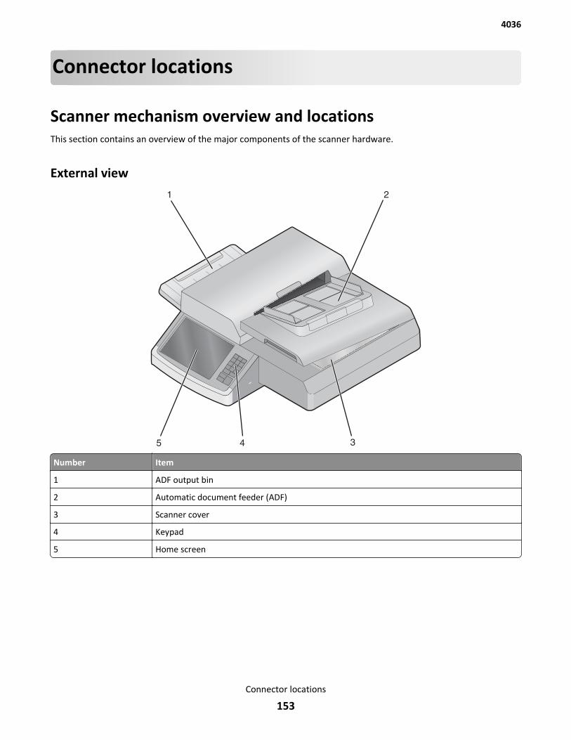
Connector locations
Scanner mechanism overview and locationsThis section contains an overview of the major components of the scanner hardware.
External view
Number Item
1 ADF output bin
2 Automatic document feeder (ADF)
3 Scanner cover
4 Keypad
5 Home screen
4036
Connector locations
153
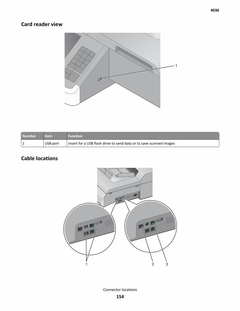
Card reader view
Number Item Function
1 USB port Insert for a USB flash drive to send data or to save scanned images
Cable locations
4036
Connector locations
154
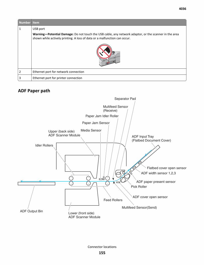
Number Item
1 USB port
Warning—Potential Damage: Do not touch the USB cable, any network adaptor, or the scanner in the areashown while actively printing. A loss of data or a malfunction can occur.
2 Ethernet port for network connection
3 Ethernet port for printer connection
ADF Paper path
4036
Connector locations
155
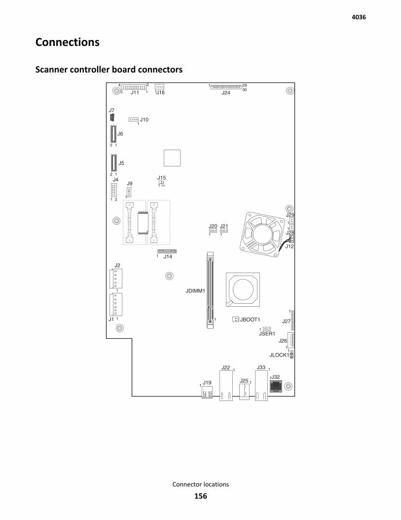
Connections
Scanner controller board connectors
4036
Connector locations
156
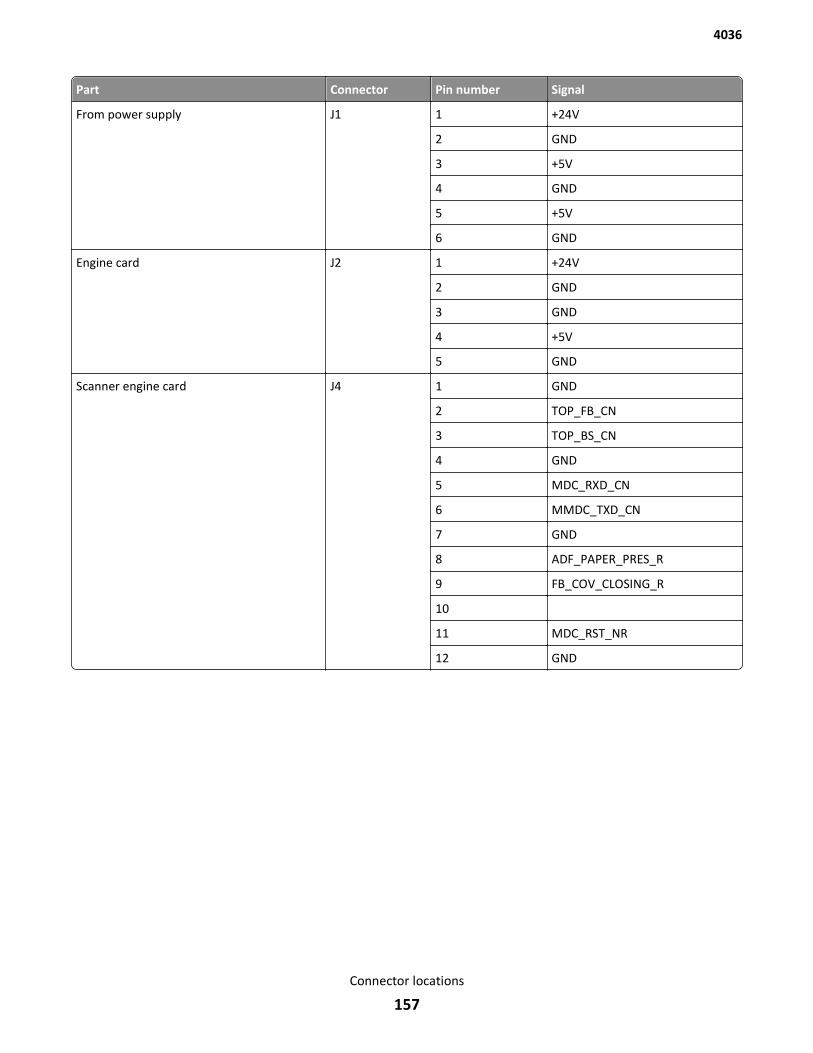
Part Connector Pin number Signal
From power supply J1 1 +24V
2 GND
3 +5V
4 GND
5 +5V
6 GND
Engine card J2 1 +24V
2 GND
3 GND
4 +5V
5 GND
Scanner engine card J4 1 GND
2 TOP_FB_CN
3 TOP_BS_CN
4 GND
5 MDC_RXD_CN
6 MMDC_TXD_CN
7 GND
8 ADF_PAPER_PRES_R
9 FB_COV_CLOSING_R
10
11 MDC_RST_NR
12 GND
4036
Connector locations
157
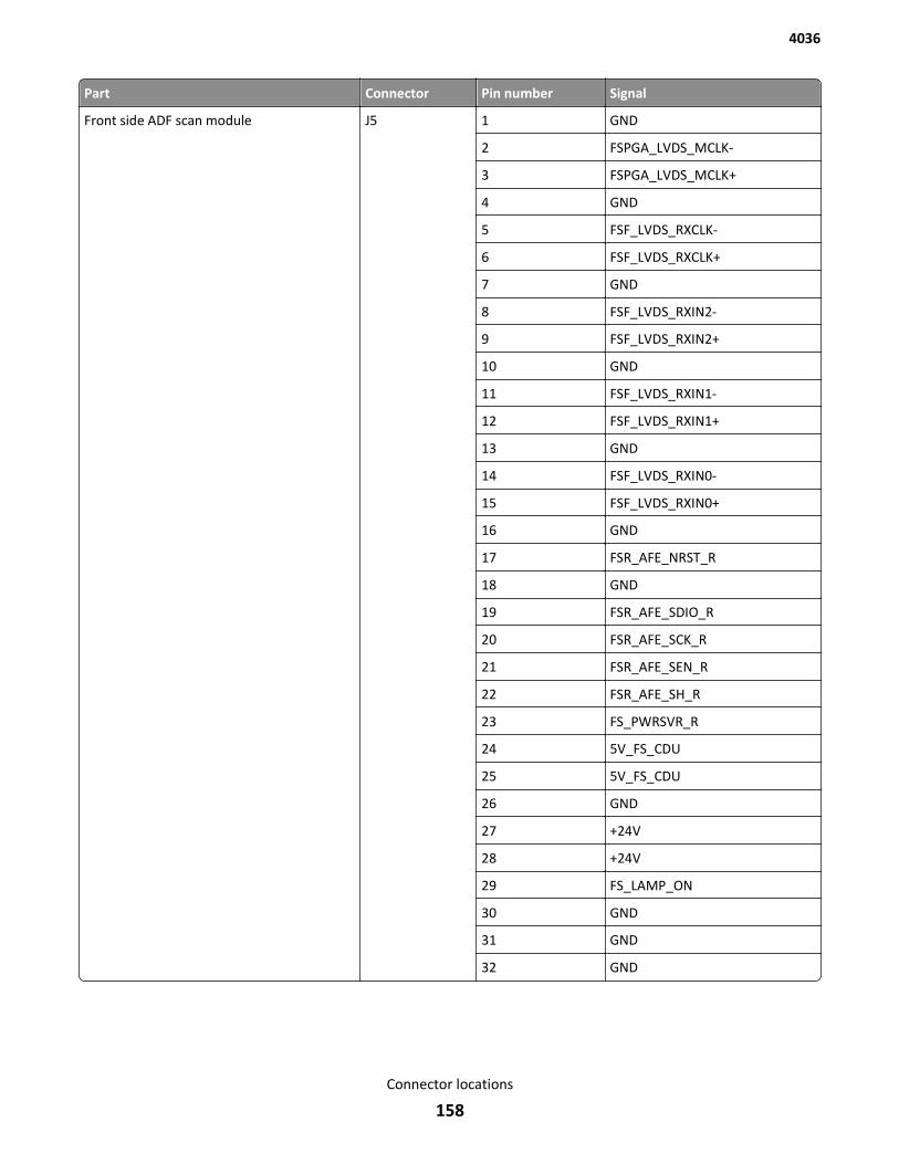
Part Connector Pin number Signal
Front side ADF scan module J5 1 GND
2 FSPGA_LVDS_MCLK-
3 FSPGA_LVDS_MCLK+
4 GND
5 FSF_LVDS_RXCLK-
6 FSF_LVDS_RXCLK+
7 GND
8 FSF_LVDS_RXIN2-
9 FSF_LVDS_RXIN2+
10 GND
11 FSF_LVDS_RXIN1-
12 FSF_LVDS_RXIN1+
13 GND
14 FSF_LVDS_RXIN0-
15 FSF_LVDS_RXIN0+
16 GND
17 FSR_AFE_NRST_R
18 GND
19 FSR_AFE_SDIO_R
20 FSR_AFE_SCK_R
21 FSR_AFE_SEN_R
22 FSR_AFE_SH_R
23 FS_PWRSVR_R
24 5V_FS_CDU
25 5V_FS_CDU
26 GND
27 +24V
28 +24V
29 FS_LAMP_ON
30 GND
31 GND
32 GND
4036
Connector locations
158

Part Connector Pin number Signal
Back side ADF scan module J6 1 GND
2 BSPGA_LVDS_MCLK-
3 FSPGA_LVDS_MCLK+
4 GND
5 BSF_LVDS_RXCLK-
6 BSF_LVDS_RXCLK+
7 GND
8 BSF_LVDS_RXIN2-
9 BSF_LVDS_RXIN2+
10 GND
11 BSF_LVDS_RXIN1-
12 BSF_LVDS_RXIN1+
13 GND
14 BSF_LVDS_RXIN0-
15 BSF_LVDS_RXIN0+
16 GND
17 BSR_AFE_NRST_R
18 GND
19 BSR_AFE_SDIO_R
20 BSR_AFE_SCK_R
21 BSR_AFE_SEN_R
22 BSR_AFE_SH_R
23 BS_PWRSVR_R
24 5V_BS_CDU
25 5V_BS_CDU
26 GND
27 +24V
28 +24V
29 BS_LAMP_ON_R
30 GND
31 GND
32 GND
4036
Connector locations
159
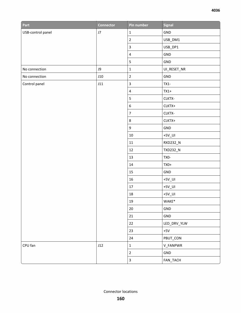
Part Connector Pin number Signal
USB-control panel J7 1 GND
2 USB_DM1
3 USB_DP1
4 GND
5 GND
No connection J9 1 UI_RESET_NR
No connection J10 2 GND
Control panel J11 3 TX1-
4 TX1+
5 CLKTX-
6 CLKTX+
7 CLKTX-
8 CLKTX+
9 GND
10 +5V_UI
11 RXD232_N
12 TXD232_N
13 TX0-
14 TX0+
15 GND
16 +5V_UI
17 +5V_UI
18 +5V_UI
19 WAKE*
20 GND
21 GND
22 LED_DRV_YLW
23 +5V
24 PBUT_CON
CPU fan J12 1 V_FANPWR
2 GND
3 FAN_TACH
4036
Connector locations
160
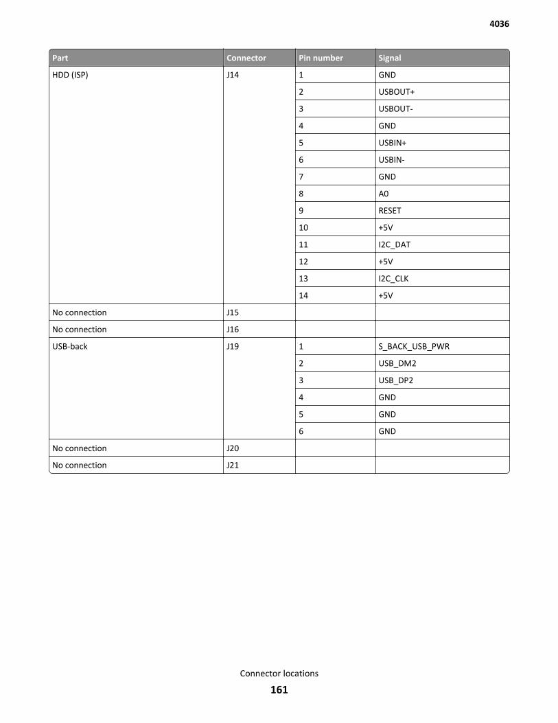
Part Connector Pin number Signal
HDD (ISP) J14 1 GND
2 USBOUT+
3 USBOUT-
4 GND
5 USBIN+
6 USBIN-
7 GND
8 A0
9 RESET
10 +5V
11 I2C_DAT
12 +5V
13 I2C_CLK
14 +5V
No connection J15
No connection J16
USB-back J19 1 S_BACK_USB_PWR
2 USB_DM2
3 USB_DP2
4 GND
5 GND
6 GND
No connection J20
No connection J21
4036
Connector locations
161
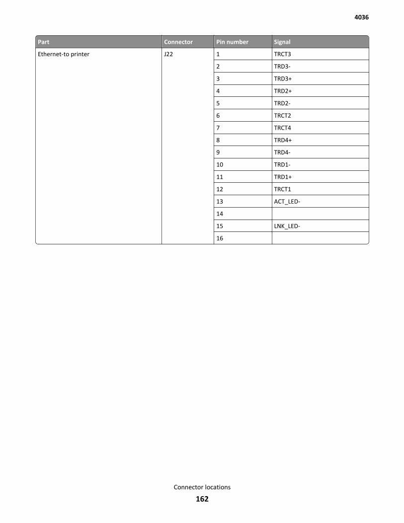
Part Connector Pin number Signal
Ethernet-to printer J22 1 TRCT3
2 TRD3-
3 TRD3+
4 TRD2+
5 TRD2-
6 TRCT2
7 TRCT4
8 TRD4+
9 TRD4-
10 TRD1-
11 TRD1+
12 TRCT1
13 ACT_LED-
14
15 LNK_LED-
16
4036
Connector locations
162
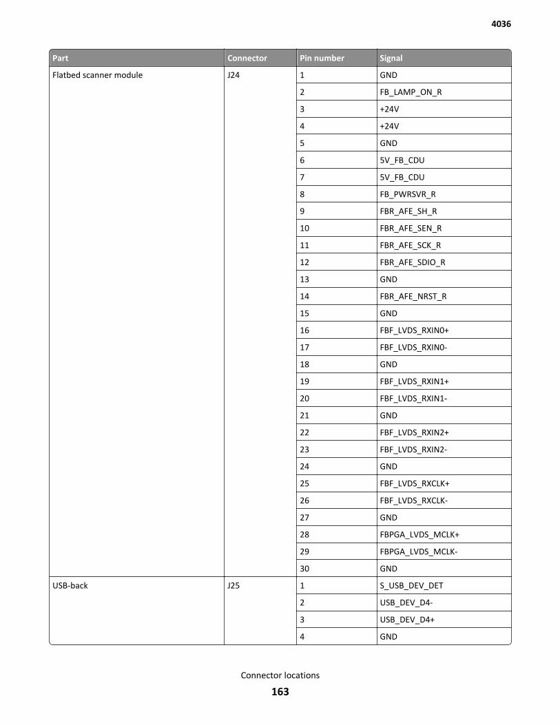
Part Connector Pin number Signal
Flatbed scanner module J24 1 GND
2 FB_LAMP_ON_R
3 +24V
4 +24V
5 GND
6 5V_FB_CDU
7 5V_FB_CDU
8 FB_PWRSVR_R
9 FBR_AFE_SH_R
10 FBR_AFE_SEN_R
11 FBR_AFE_SCK_R
12 FBR_AFE_SDIO_R
13 GND
14 FBR_AFE_NRST_R
15 GND
16 FBF_LVDS_RXIN0+
17 FBF_LVDS_RXIN0-
18 GND
19 FBF_LVDS_RXIN1+
20 FBF_LVDS_RXIN1-
21 GND
22 FBF_LVDS_RXIN2+
23 FBF_LVDS_RXIN2-
24 GND
25 FBF_LVDS_RXCLK+
26 FBF_LVDS_RXCLK-
27 GND
28 FBPGA_LVDS_MCLK+
29 FBPGA_LVDS_MCLK-
30 GND
USB-back J25 1 S_USB_DEV_DET
2 USB_DEV_D4-
3 USB_DEV_D4+
4 GND
4036
Connector locations
163
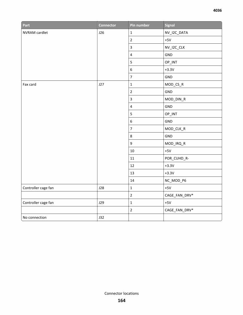
Part Connector Pin number Signal
NVRAM cardlet J26 1 NV_I2C_DATA
2 +5V
3 NV_I2C_CLK
4 GND
5 OP_INT
6 +3.3V
7 GND
Fax card J27 1 MOD_CS_R
2 GND
3 MOD_DIN_R
4 GND
5 OP_INT
6 GND
7 MOD_CLK_R
8 GND
9 MOD_IRQ_R
10 +5V
11 POR_CUHD_R-
12 +3.3V
13 +3.3V
14 NC_MOD_P6
Controller cage fan J28 1 +5V
2 CAGE_FAN_DRV*
Controller cage fan J29 1 +5V
2 CAGE_FAN_DRV*
No connection J32
4036
Connector locations
164
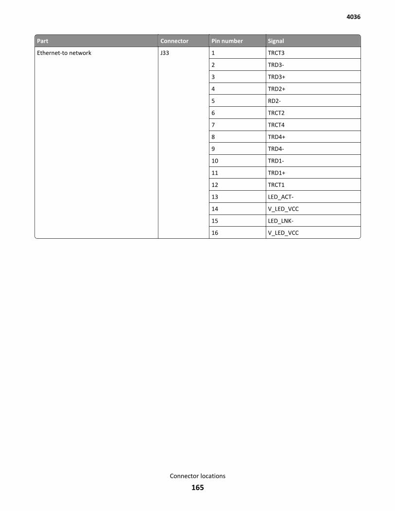
Part Connector Pin number Signal
Ethernet-to network J33 1 TRCT3
2 TRD3-
3 TRD3+
4 TRD2+
5 RD2-
6 TRCT2
7 TRCT4
8 TRD4+
9 TRD4-
10 TRD1-
11 TRD1+
12 TRCT1
13 LED_ACT-
14 V_LED_VCC
15 LED_LNK-
16 V_LED_VCC
4036
Connector locations
165
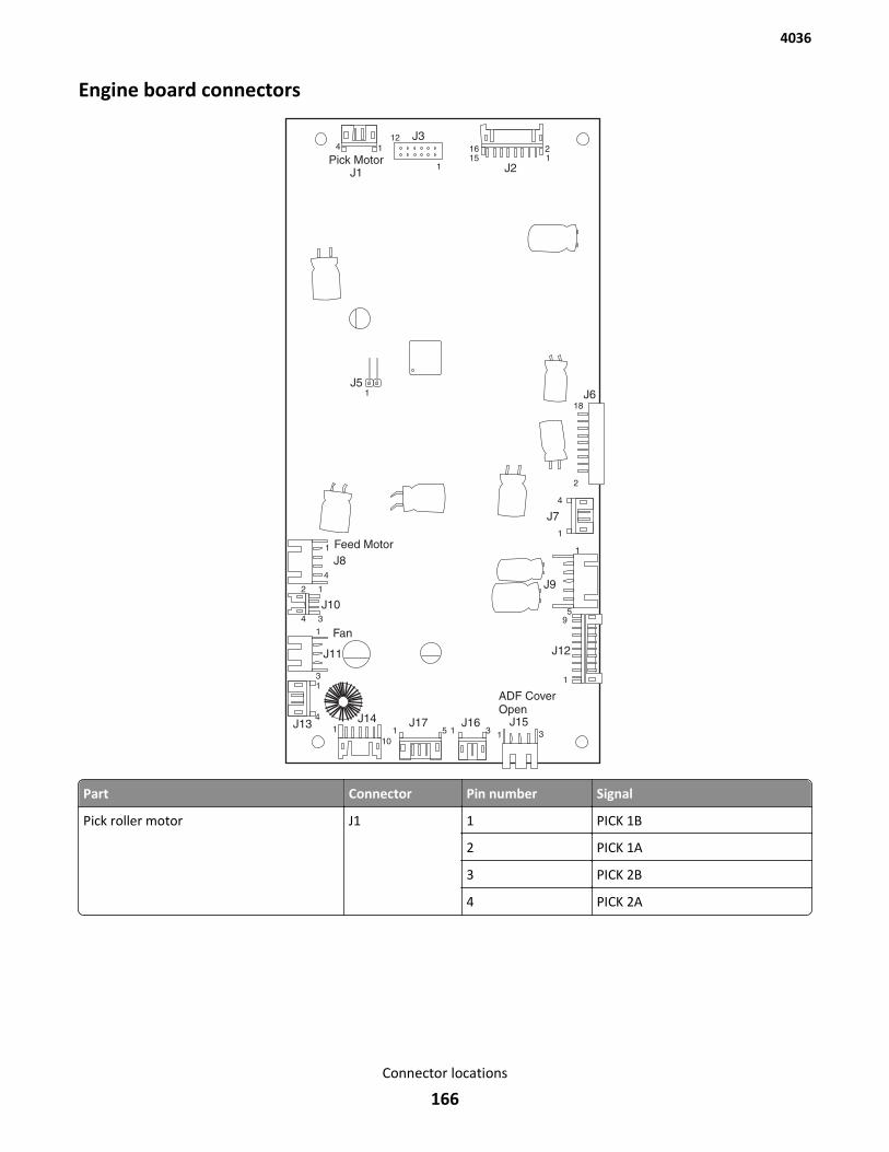
Engine board connectors
Part Connector Pin number Signal
Pick roller motor J1 1 PICK 1B
2 PICK 1A
3 PICK 2B
4 PICK 2A
4036
Connector locations
166
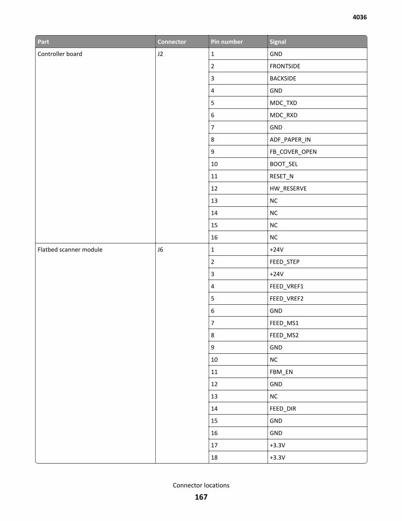
Part Connector Pin number Signal
Controller board J2 1 GND
2 FRONTSIDE
3 BACKSIDE
4 GND
5 MDC_TXD
6 MDC_RXD
7 GND
8 ADF_PAPER_IN
9 FB_COVER_OPEN
10 BOOT_SEL
11 RESET_N
12 HW_RESERVE
13 NC
14 NC
15 NC
16 NC
Flatbed scanner module J6 1 +24V
2 FEED_STEP
3 +24V
4 FEED_VREF1
5 FEED_VREF2
6 GND
7 FEED_MS1
8 FEED_MS2
9 GND
10 NC
11 FBM_EN
12 GND
13 NC
14 FEED_DIR
15 GND
16 GND
17 +3.3V
18 +3.3V
4036
Connector locations
167
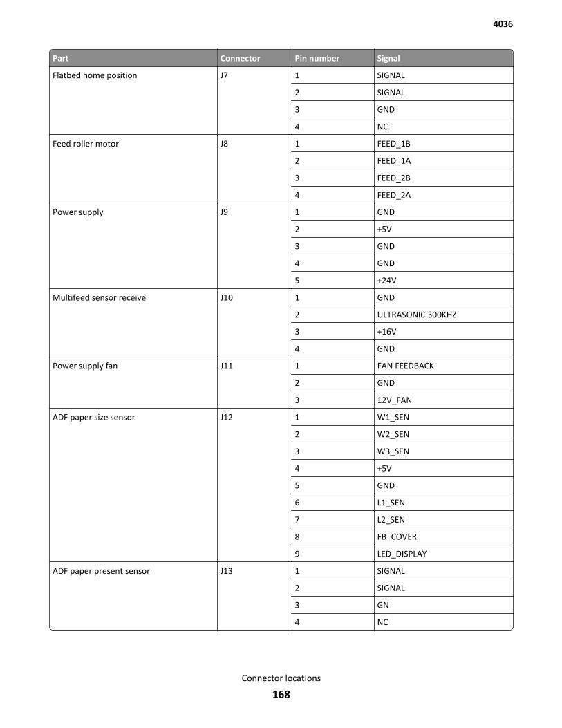
Part Connector Pin number Signal
Flatbed home position J7 1 SIGNAL
2 SIGNAL
3 GND
4 NC
Feed roller motor J8 1 FEED_1B
2 FEED_1A
3 FEED_2B
4 FEED_2A
Power supply J9 1 GND
2 +5V
3 GND
4 GND
5 +24V
Multifeed sensor receive J10 1 GND
2 ULTRASONIC 300KHZ
3 +16V
4 GND
Power supply fan J11 1 FAN FEEDBACK
2 GND
3 12V_FAN
ADF paper size sensor J12 1 W1_SEN
2 W2_SEN
3 W3_SEN
4 +5V
5 GND
6 L1_SEN
7 L2_SEN
8 FB_COVER
9 LED_DISPLAY
ADF paper present sensor J13 1 SIGNAL
2 SIGNAL
3 GN
4 NC
4036
Connector locations
168
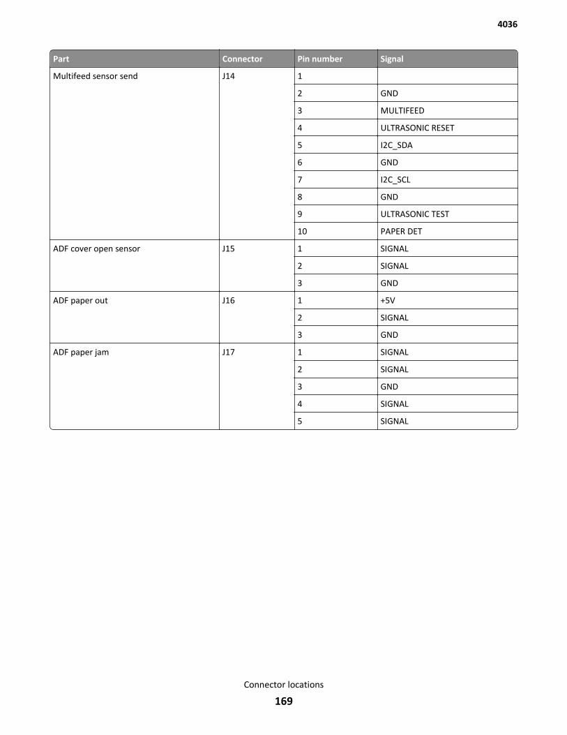
Part Connector Pin number Signal
Multifeed sensor send J14 1
2 GND
3 MULTIFEED
4 ULTRASONIC RESET
5 I2C_SDA
6 GND
7 I2C_SCL
8 GND
9 ULTRASONIC TEST
10 PAPER DET
ADF cover open sensor J15 1 SIGNAL
2 SIGNAL
3 GND
ADF paper out J16 1 +5V
2 SIGNAL
3 GND
ADF paper jam J17 1 SIGNAL
2 SIGNAL
3 GND
4 SIGNAL
5 SIGNAL
4036
Connector locations
169
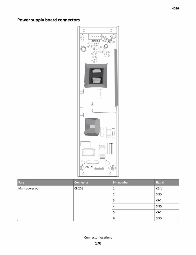
Power supply board connectors
Part Connector Pin number Signal
Main power out CN201 1 +24V
2 GND
3 +5V
4 GND
5 +5V
6 GND
4036
Connector locations
170
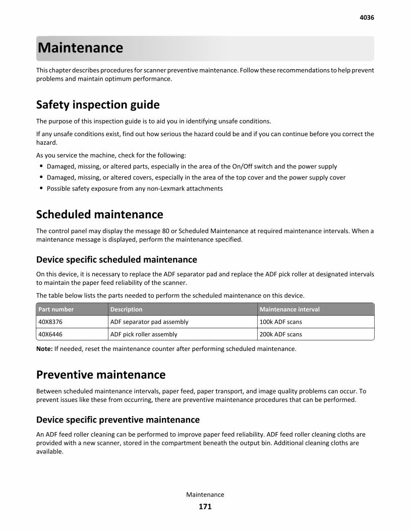
MaintenanceThis chapter describes procedures for scanner preventive maintenance. Follow these recommendations to help preventproblems and maintain optimum performance.
Safety inspection guideThe purpose of this inspection guide is to aid you in identifying unsafe conditions.
If any unsafe conditions exist, find out how serious the hazard could be and if you can continue before you correct thehazard.
As you service the machine, check for the following:
• Damaged, missing, or altered parts, especially in the area of the On/Off switch and the power supply
• Damaged, missing, or altered covers, especially in the area of the top cover and the power supply cover
• Possible safety exposure from any non-Lexmark attachments
Scheduled maintenanceThe control panel may display the message 80 or Scheduled Maintenance at required maintenance intervals. When amaintenance message is displayed, perform the maintenance specified.
Device specific scheduled maintenanceOn this device, it is necessary to replace the ADF separator pad and replace the ADF pick roller at designated intervalsto maintain the paper feed reliability of the scanner.
The table below lists the parts needed to perform the scheduled maintenance on this device.
Part number Description Maintenance interval
40X8376 ADF separator pad assembly 100k ADF scans
40X6446 ADF pick roller assembly 200k ADF scans
Note: If needed, reset the maintenance counter after performing scheduled maintenance.
Preventive maintenanceBetween scheduled maintenance intervals, paper feed, paper transport, and image quality problems can occur. Toprevent issues like these from occurring, there are preventive maintenance procedures that can be performed.
Device specific preventive maintenanceAn ADF feed roller cleaning can be performed to improve paper feed reliability. ADF feed roller cleaning cloths areprovided with a new scanner, stored in the compartment beneath the output bin. Additional cleaning cloths areavailable.
4036
Maintenance
171
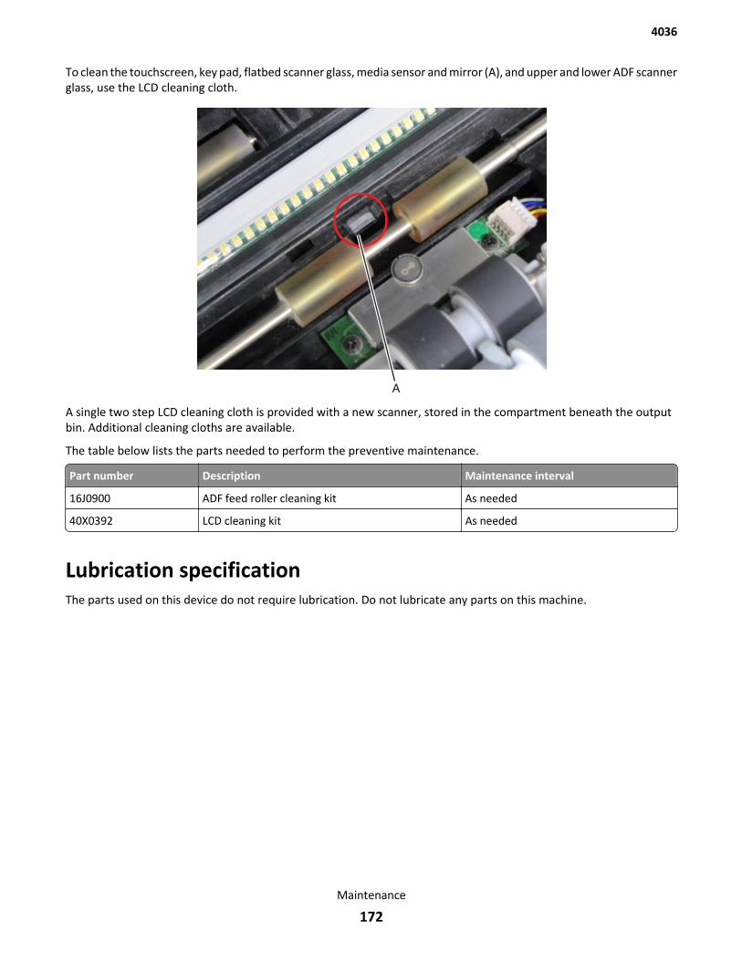
To clean the touchscreen, key pad, flatbed scanner glass, media sensor and mirror (A), and upper and lower ADF scannerglass, use the LCD cleaning cloth.
A single two step LCD cleaning cloth is provided with a new scanner, stored in the compartment beneath the outputbin. Additional cleaning cloths are available.
The table below lists the parts needed to perform the preventive maintenance.
Part number Description Maintenance interval
16J0900 ADF feed roller cleaning kit As needed
40X0392 LCD cleaning kit As needed
Lubrication specificationThe parts used on this device do not require lubrication. Do not lubricate any parts on this machine.
4036
Maintenance
172

4036
173
Parts catalog
LegendThe following column headings are used in the parts catalog:
• Asm‑index—Identifies the assembly and the item in the diagram. For example, 3‑1 indicates Assembly 3 and item1 in the table.
• Part number—Identifies the unique number that correlates with the part.
• Units/mach—Refers to the number of units actually used in the base machine or product.
• Units/option—Refers to the number of units in a particular option.
• Description—A brief description of the part.
The following abbreviations are used in the parts catalog:
• NS (not shown) in the Asm‑index column indicates that the part is procurable but is not pictured in the illustration.
• PP (parts packet) in the Description column indicates that the part is contained in a parts packet.
4036
Parts catalog
174
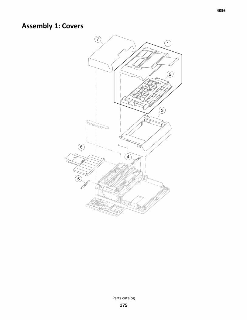
Assembly 1: Covers
4036
Parts catalog
175
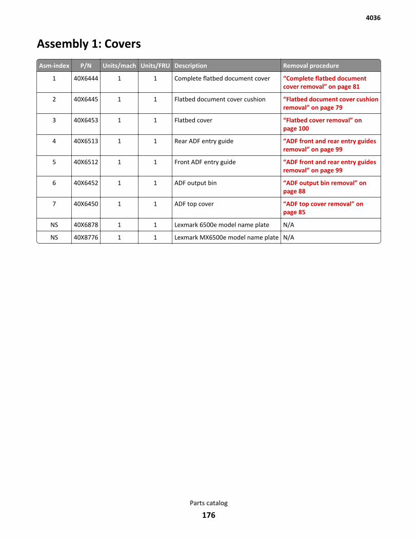
Assembly 1: Covers
Asm-index P/N Units/mach Units/FRU Description Removal procedure
1 40X6444 1 1 Complete flatbed document cover “Complete flatbed documentcover removal” on page 81
2 40X6445 1 1 Flatbed document cover cushion “Flatbed document cover cushionremoval” on page 79
3 40X6453 1 1 Flatbed cover “Flatbed cover removal” onpage 100
4 40X6513 1 1 Rear ADF entry guide “ADF front and rear entry guidesremoval” on page 99
5 40X6512 1 1 Front ADF entry guide “ADF front and rear entry guidesremoval” on page 99
6 40X6452 1 1 ADF output bin “ADF output bin removal” onpage 88
7 40X6450 1 1 ADF top cover “ADF top cover removal” onpage 85
NS 40X6878 1 1 Lexmark 6500e model name plate N/A
NS 40X8776 1 1 Lexmark MX6500e model name plate N/A
4036
Parts catalog
176
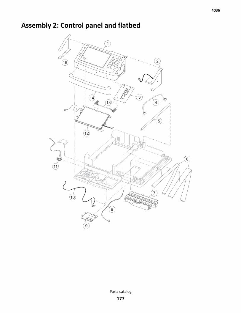
Assembly 2: Control panel and flatbed
4036
Parts catalog
177
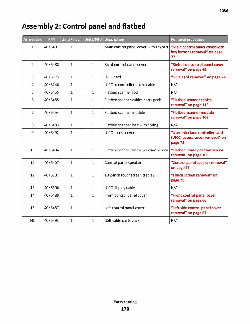
Assembly 2: Control panel and flatbed
Asm-index P/N Units/mach Units/FRU Description Removal procedure
1 40X6491 1 1 Main control panel cover with keypad “Main control panel cover withkey buttons removal” on page 77
2 40X6488 1 1 Right control panel cover “Right side control panel coverremoval” on page 69
3 40X6973 1 1 UICC card “UICC card removal” on page 74
4 40X8746 1 1 UICC to controller board cable N/A
5 40X6455 1 1 Flatbed scanner rod N/A
6 40X6485 1 1 Flatbed scanner cables parts pack “Flatbed scanner cablesremoval” on page 113
7 40X6454 1 1 Flatbed scanner module “Flatbed scanner moduleremoval” on page 103
8 40X6483 1 1 Flatbed scanner belt with spring N/A
9 40X6492 1 1 UICC access cover “User interface controller card(UICC) access cover removal” onpage 71
10 40X6484 1 1 Flatbed scanner home position sensor “Flatbed home position sensorremoval” on page 106
11 40X6407 1 1 Control panel speaker “Control panel speaker removal”on page 77
12 40X6307 1 1 10.2-inch touchscreen display “Touch screen removal” onpage 75
13 40X6306 1 1 UICC display cable N/A
14 40X6489 1 1 Front control panel cover “Front control panel coverremoval” on page 66
15 40X6487 1 1 Left control panel cover “Left side control panel coverremoval” on page 67
NS 40X6493 1 1 USB cable parts pack N/A
4036
Parts catalog
178
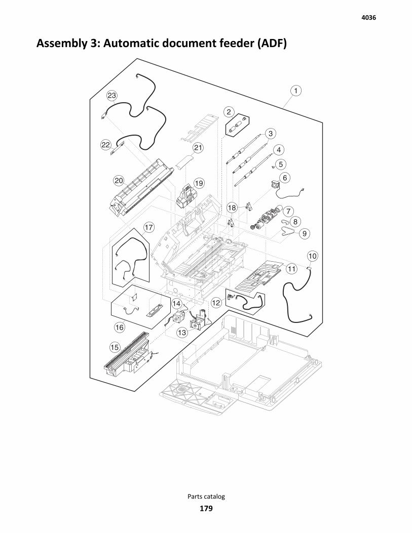
Assembly 3: Automatic document feeder (ADF)
4036
Parts catalog
179
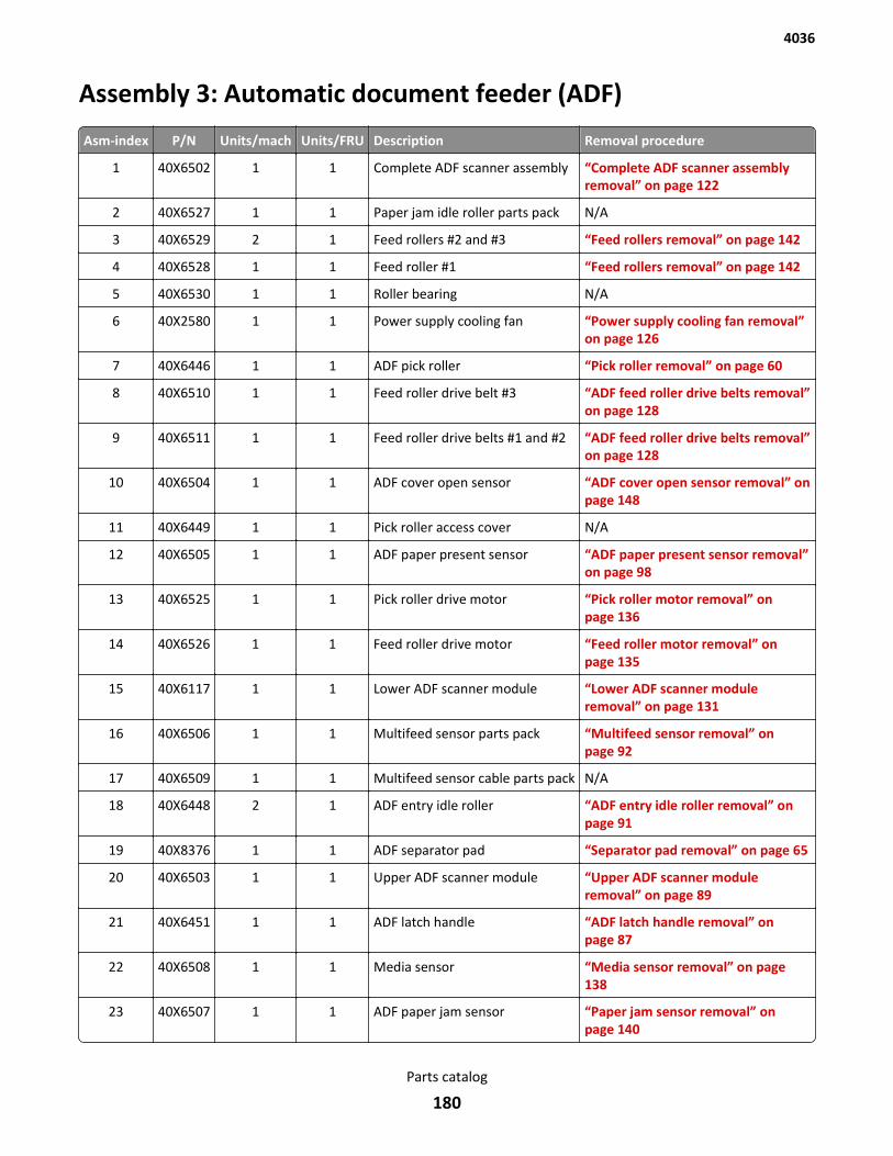
Assembly 3: Automatic document feeder (ADF)
Asm-index P/N Units/mach Units/FRU Description Removal procedure
1 40X6502 1 1 Complete ADF scanner assembly “Complete ADF scanner assemblyremoval” on page 122
2 40X6527 1 1 Paper jam idle roller parts pack N/A
3 40X6529 2 1 Feed rollers #2 and #3 “Feed rollers removal” on page 142
4 40X6528 1 1 Feed roller #1 “Feed rollers removal” on page 142
5 40X6530 1 1 Roller bearing N/A
6 40X2580 1 1 Power supply cooling fan “Power supply cooling fan removal”on page 126
7 40X6446 1 1 ADF pick roller “Pick roller removal” on page 60
8 40X6510 1 1 Feed roller drive belt #3 “ADF feed roller drive belts removal”on page 128
9 40X6511 1 1 Feed roller drive belts #1 and #2 “ADF feed roller drive belts removal”on page 128
10 40X6504 1 1 ADF cover open sensor “ADF cover open sensor removal” onpage 148
11 40X6449 1 1 Pick roller access cover N/A
12 40X6505 1 1 ADF paper present sensor “ADF paper present sensor removal”on page 98
13 40X6525 1 1 Pick roller drive motor “Pick roller motor removal” onpage 136
14 40X6526 1 1 Feed roller drive motor “Feed roller motor removal” onpage 135
15 40X6117 1 1 Lower ADF scanner module “Lower ADF scanner moduleremoval” on page 131
16 40X6506 1 1 Multifeed sensor parts pack “Multifeed sensor removal” onpage 92
17 40X6509 1 1 Multifeed sensor cable parts pack N/A
18 40X6448 2 1 ADF entry idle roller “ADF entry idle roller removal” onpage 91
19 40X8376 1 1 ADF separator pad “Separator pad removal” on page 65
20 40X6503 1 1 Upper ADF scanner module “Upper ADF scanner moduleremoval” on page 89
21 40X6451 1 1 ADF latch handle “ADF latch handle removal” onpage 87
22 40X6508 1 1 Media sensor “Media sensor removal” on page 138
23 40X6507 1 1 ADF paper jam sensor “Paper jam sensor removal” onpage 140
4036
Parts catalog
180
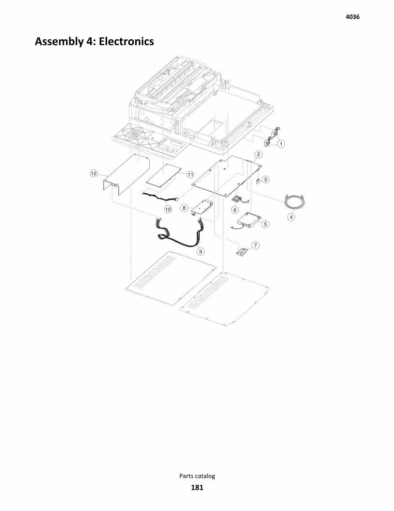
Assembly 4: Electronics
4036
Parts catalog
181
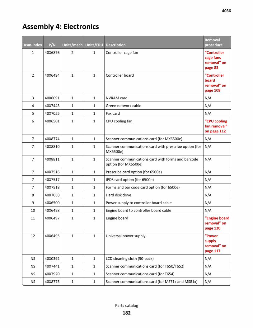
Assembly 4: Electronics
Asm-index P/N Units/mach Units/FRU DescriptionRemovalprocedure
1 40X6876 2 1 Controller cage fan “Controllercage fansremoval” onpage 83
2 40X6494 1 1 Controller board “Controllerboardremoval” onpage 109
3 40X6091 1 1 NVRAM card N/A
4 40X7443 1 1 Green network cable N/A
5 40X7055 1 1 Fax card N/A
6 40X6501 1 1 CPU cooling fan “CPU coolingfan removal”on page 112
7 40X8774 1 1 Scanner communications card (for MX6500e) N/A
7 40X8810 1 1 Scanner communications card with prescribe option (forMX6500e)
N/A
7 40X8811 1 1 Scanner communications card with forms and barcodeoption (for MX6500e)
N/A
7 40X7516 1 1 Prescribe card option (for 6500e) N/A
7 40X7517 1 1 IPDS card option (for 6500e) N/A
7 40X7518 1 1 Forms and bar code card option (for 6500e) N/A
8 40X7058 1 1 Hard disk drive N/A
9 40X6500 1 1 Power supply to controller board cable N/A
10 40X6498 1 1 Engine board to controller board cable N/A
11 40X6497 1 1 Engine board “Engine boardremoval” onpage 120
12 40X6495 1 1 Universal power supply “Powersupplyremoval” onpage 117
NS 40X0392 1 1 LCD cleaning cloth (50-pack) N/A
NS 40X7441 1 1 Scanner communications card (for T650/T652) N/A
NS 40X7920 1 1 Scanner communications card (for T654) N/A
NS 40X8775 1 1 Scanner communications card (for MS71x and MS81x) N/A
4036
Parts catalog
182

Appendix A: Acronyms
AcronymsADF Automatic Document Feeder
CCD Charge‑coupled Device
CCFL Cold Cathode Fluorescent Lamp
CDB Command Descriptor Blocks
CRU Customer Replaceable Unit
ESD Electrostatic Discharge
FRU Field Replaceable Unit
HV High Voltage
LCM Liquid Crystal Module
LED Light-Emitting Diode
LV Low Voltage
MFD Multifunction Device
PCBA Printed Circuit Board Assembly
PPM Page per minute
SPM Sides per minute
V ac Volts alternating current
V dc Volts direct current
4036
Appendix A: Acronyms
183
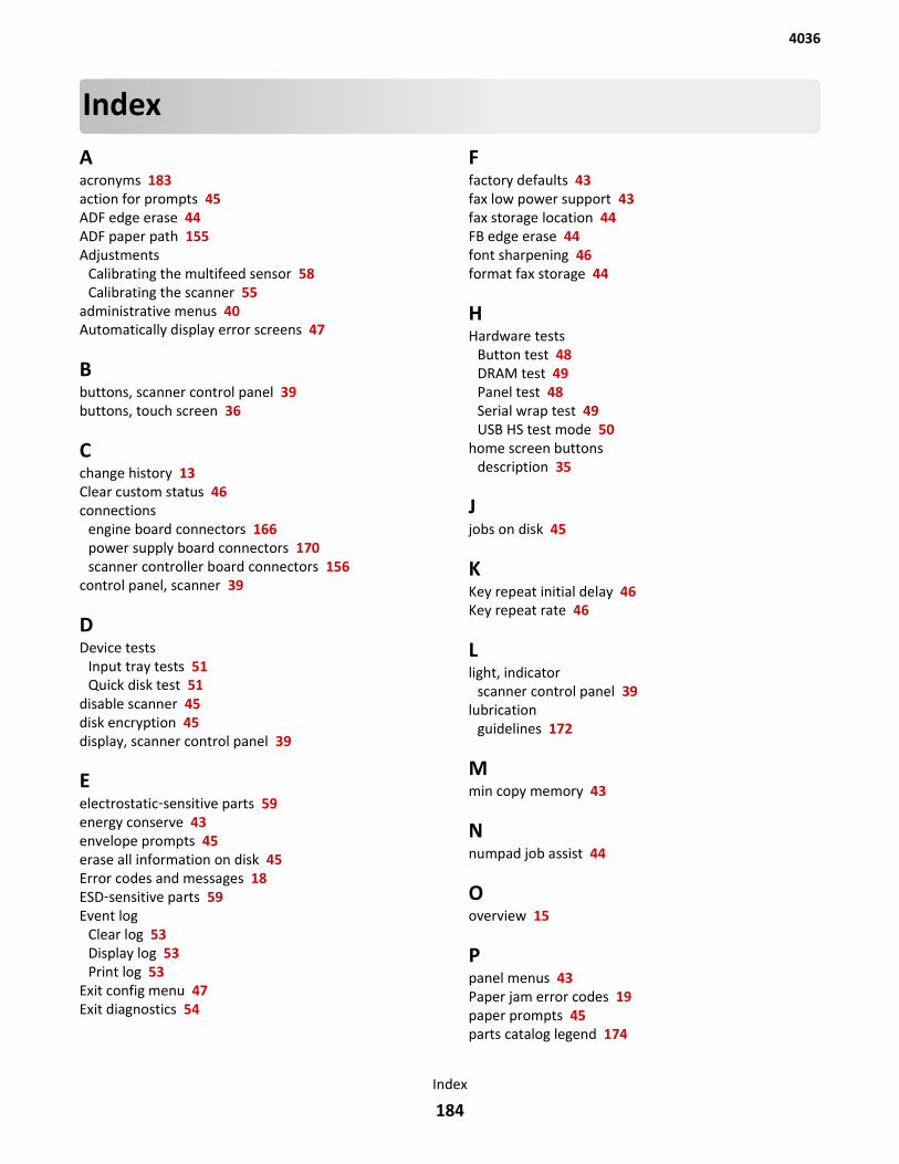
IndexAacronyms 183action for prompts 45ADF edge erase 44ADF paper path 155Adjustments
Calibrating the multifeed sensor 58Calibrating the scanner 55
administrative menus 40Automatically display error screens 47
Bbuttons, scanner control panel 39buttons, touch screen 36
Cchange history 13Clear custom status 46connections
engine board connectors 166power supply board connectors 170scanner controller board connectors 156
control panel, scanner 39
DDevice tests
Input tray tests 51Quick disk test 51
disable scanner 45disk encryption 45display, scanner control panel 39
Eelectrostatic‑sensitive parts 59energy conserve 43envelope prompts 45erase all information on disk 45Error codes and messages 18ESD‑sensitive parts 59Event log
Clear log 53Display log 53Print log 53
Exit config menu 47Exit diagnostics 54
Ffactory defaults 43fax low power support 43fax storage location 44FB edge erase 44font sharpening 46format fax storage 44
HHardware tests
Button test 48DRAM test 49Panel test 48Serial wrap test 49USB HS test mode 50
home screen buttons description 35
Jjobs on disk 45
KKey repeat initial delay 46Key repeat rate 46
Llight, indicator
scanner control panel 39lubrication
guidelines 172
Mmin copy memory 43
Nnumpad job assist 44
Ooverview 15
Ppanel menus 43Paper jam error codes 19paper prompts 45parts catalog legend 174
4036
Index
184
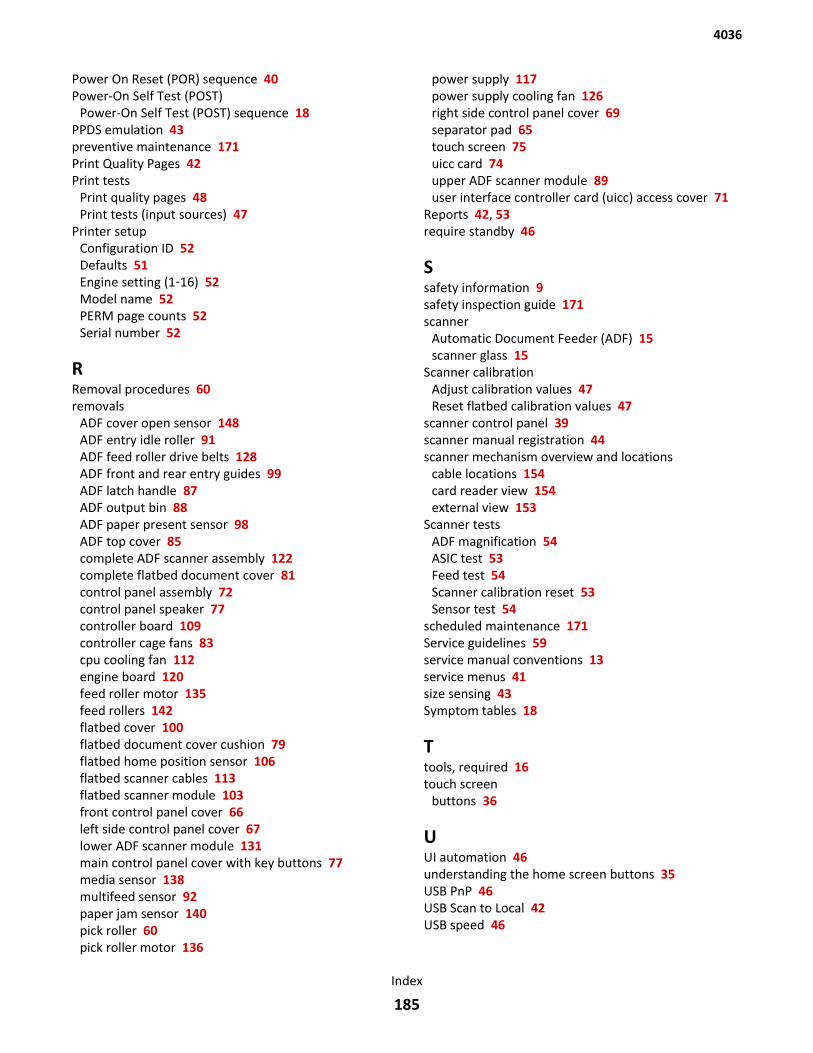
Power On Reset (POR) sequence 40Power-On Self Test (POST)
Power-On Self Test (POST) sequence 18PPDS emulation 43preventive maintenance 171Print Quality Pages 42Print tests
Print quality pages 48Print tests (input sources) 47
Printer setup Configuration ID 52Defaults 51Engine setting (1‑16) 52Model name 52PERM page counts 52Serial number 52
RRemoval procedures 60removals
ADF cover open sensor 148ADF entry idle roller 91ADF feed roller drive belts 128ADF front and rear entry guides 99ADF latch handle 87ADF output bin 88ADF paper present sensor 98ADF top cover 85complete ADF scanner assembly 122complete flatbed document cover 81control panel assembly 72control panel speaker 77controller board 109controller cage fans 83cpu cooling fan 112engine board 120feed roller motor 135feed rollers 142flatbed cover 100flatbed document cover cushion 79flatbed home position sensor 106flatbed scanner cables 113flatbed scanner module 103front control panel cover 66left side control panel cover 67lower ADF scanner module 131main control panel cover with key buttons 77media sensor 138multifeed sensor 92paper jam sensor 140pick roller 60pick roller motor 136
power supply 117power supply cooling fan 126right side control panel cover 69separator pad 65touch screen 75uicc card 74upper ADF scanner module 89user interface controller card (uicc) access cover 71
Reports 42, 53require standby 46
Ssafety information 9safety inspection guide 171scanner
Automatic Document Feeder (ADF) 15scanner glass 15
Scanner calibration Adjust calibration values 47Reset flatbed calibration values 47
scanner control panel 39scanner manual registration 44scanner mechanism overview and locations
cable locations 154card reader view 154external view 153
Scanner tests ADF magnification 54ASIC test 53Feed test 54Scanner calibration reset 53Sensor test 54
scheduled maintenance 171Service guidelines 59service manual conventions 13service menus 41size sensing 43Symptom tables 18
Ttools, required 16touch screen
buttons 36
UUI automation 46understanding the home screen buttons 35USB PnP 46USB Scan to Local 42USB speed 46
4036
Index
185

4036
Index
186
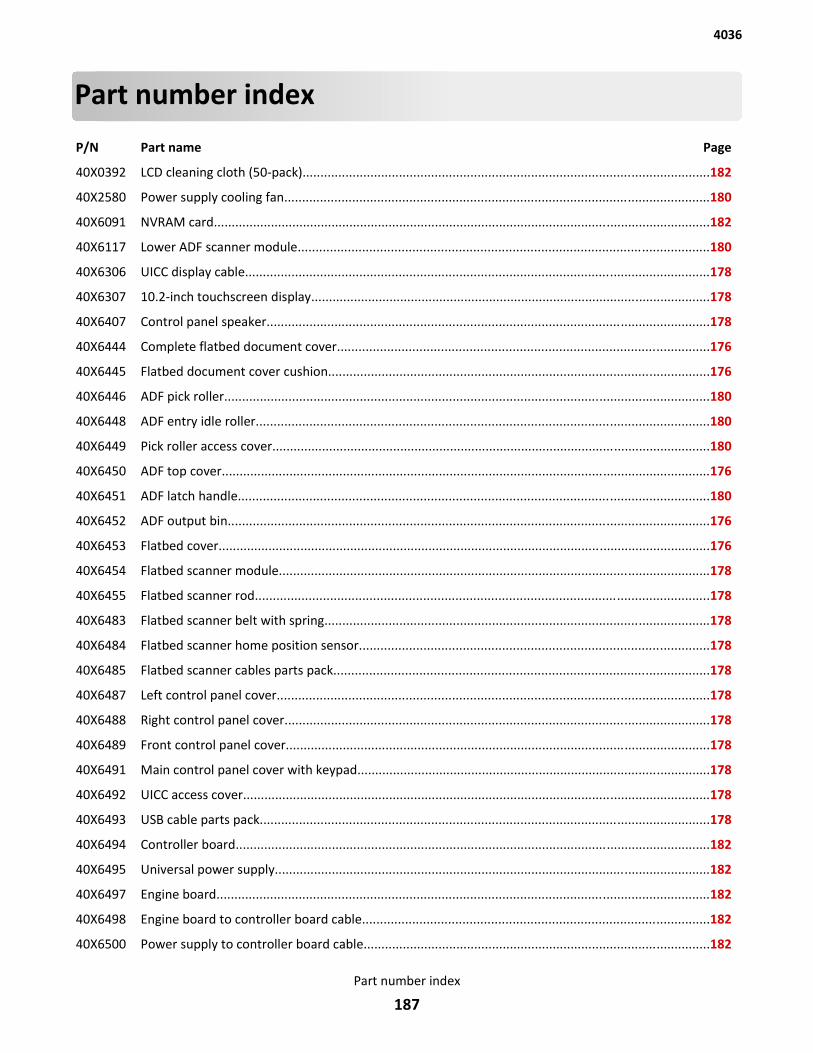
Part number index
P/N Part name Page
40X0392 LCD cleaning cloth (50-pack)..................................................................................................................182
40X2580 Power supply cooling fan.......................................................................................................................180
40X6091 NVRAM card...........................................................................................................................................182
40X6117 Lower ADF scanner module...................................................................................................................180
40X6306 UICC display cable..................................................................................................................................178
40X6307 10.2-inch touchscreen display................................................................................................................178
40X6407 Control panel speaker............................................................................................................................178
40X6444 Complete flatbed document cover........................................................................................................176
40X6445 Flatbed document cover cushion...........................................................................................................176
40X6446 ADF pick roller........................................................................................................................................180
40X6448 ADF entry idle roller...............................................................................................................................180
40X6449 Pick roller access cover...........................................................................................................................180
40X6450 ADF top cover.........................................................................................................................................176
40X6451 ADF latch handle....................................................................................................................................180
40X6452 ADF output bin.......................................................................................................................................176
40X6453 Flatbed cover..........................................................................................................................................176
40X6454 Flatbed scanner module.........................................................................................................................178
40X6455 Flatbed scanner rod...............................................................................................................................178
40X6483 Flatbed scanner belt with spring............................................................................................................178
40X6484 Flatbed scanner home position sensor..................................................................................................178
40X6485 Flatbed scanner cables parts pack.........................................................................................................178
40X6487 Left control panel cover.........................................................................................................................178
40X6488 Right control panel cover.......................................................................................................................178
40X6489 Front control panel cover.......................................................................................................................178
40X6491 Main control panel cover with keypad...................................................................................................178
40X6492 UICC access cover...................................................................................................................................178
40X6493 USB cable parts pack..............................................................................................................................178
40X6494 Controller board.....................................................................................................................................182
40X6495 Universal power supply..........................................................................................................................182
40X6497 Engine board..........................................................................................................................................182
40X6498 Engine board to controller board cable.................................................................................................182
40X6500 Power supply to controller board cable.................................................................................................182
4036
Part number index
187
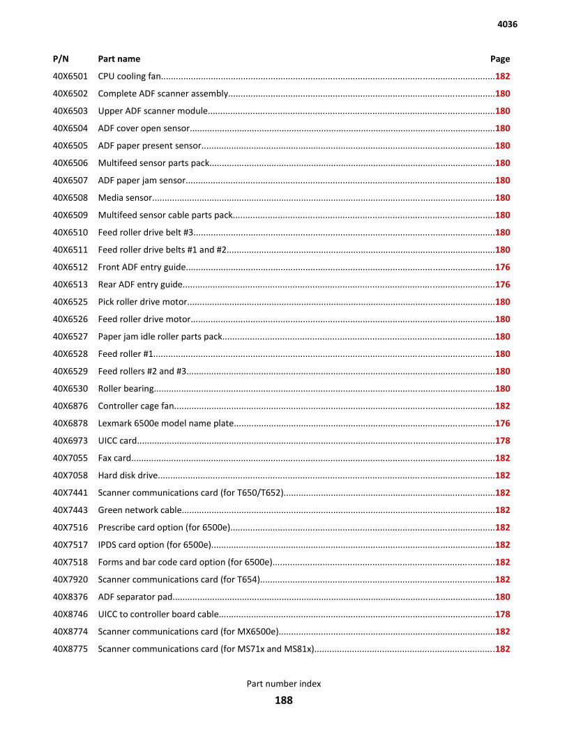
P/N Part name Page
40X6501 CPU cooling fan......................................................................................................................................182
40X6502 Complete ADF scanner assembly...........................................................................................................180
40X6503 Upper ADF scanner module...................................................................................................................180
40X6504 ADF cover open sensor...........................................................................................................................180
40X6505 ADF paper present sensor......................................................................................................................180
40X6506 Multifeed sensor parts pack...................................................................................................................180
40X6507 ADF paper jam sensor............................................................................................................................180
40X6508 Media sensor..........................................................................................................................................180
40X6509 Multifeed sensor cable parts pack.........................................................................................................180
40X6510 Feed roller drive belt #3.........................................................................................................................180
40X6511 Feed roller drive belts #1 and #2............................................................................................................180
40X6512 Front ADF entry guide............................................................................................................................176
40X6513 Rear ADF entry guide.............................................................................................................................176
40X6525 Pick roller drive motor............................................................................................................................180
40X6526 Feed roller drive motor..........................................................................................................................180
40X6527 Paper jam idle roller parts pack.............................................................................................................180
40X6528 Feed roller #1.........................................................................................................................................180
40X6529 Feed rollers #2 and #3............................................................................................................................180
40X6530 Roller bearing.........................................................................................................................................180
40X6876 Controller cage fan.................................................................................................................................182
40X6878 Lexmark 6500e model name plate.........................................................................................................176
40X6973 UICC card................................................................................................................................................178
40X7055 Fax card..................................................................................................................................................182
40X7058 Hard disk drive.......................................................................................................................................182
40X7441 Scanner communications card (for T650/T652).....................................................................................182
40X7443 Green network cable..............................................................................................................................182
40X7516 Prescribe card option (for 6500e)..........................................................................................................182
40X7517 IPDS card option (for 6500e)..................................................................................................................182
40X7518 Forms and bar code card option (for 6500e).........................................................................................182
40X7920 Scanner communications card (for T654)..............................................................................................182
40X8376 ADF separator pad..................................................................................................................................180
40X8746 UICC to controller board cable...............................................................................................................178
40X8774 Scanner communications card (for MX6500e).......................................................................................182
40X8775 Scanner communications card (for MS71x and MS81x)........................................................................182
4036
Part number index
188

P/N Part name Page
40X8776 Lexmark MX6500e model name plate...................................................................................................176
40X8810 Scanner communications card with prescribe option (for MX6500e)...................................................182
40X8811 Scanner communications card with forms and barcode option (for MX6500e)....................................182
4036
Part number index
189

4036
Part number index
190
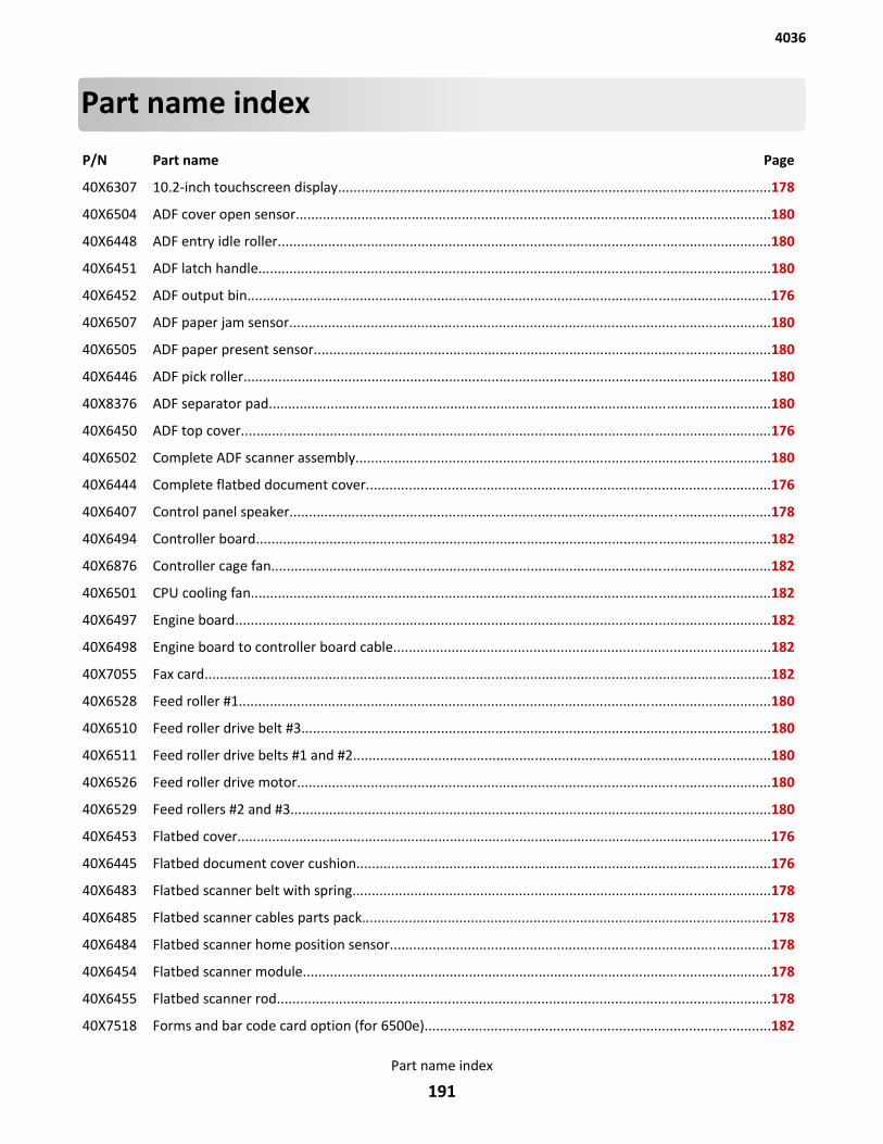
Part name index
P/N Part name Page
40X6307 10.2-inch touchscreen display................................................................................................................178
40X6504 ADF cover open sensor...........................................................................................................................180
40X6448 ADF entry idle roller...............................................................................................................................180
40X6451 ADF latch handle....................................................................................................................................180
40X6452 ADF output bin.......................................................................................................................................176
40X6507 ADF paper jam sensor............................................................................................................................180
40X6505 ADF paper present sensor......................................................................................................................180
40X6446 ADF pick roller........................................................................................................................................180
40X8376 ADF separator pad..................................................................................................................................180
40X6450 ADF top cover.........................................................................................................................................176
40X6502 Complete ADF scanner assembly...........................................................................................................180
40X6444 Complete flatbed document cover........................................................................................................176
40X6407 Control panel speaker............................................................................................................................178
40X6494 Controller board.....................................................................................................................................182
40X6876 Controller cage fan.................................................................................................................................182
40X6501 CPU cooling fan......................................................................................................................................182
40X6497 Engine board..........................................................................................................................................182
40X6498 Engine board to controller board cable.................................................................................................182
40X7055 Fax card..................................................................................................................................................182
40X6528 Feed roller #1.........................................................................................................................................180
40X6510 Feed roller drive belt #3.........................................................................................................................180
40X6511 Feed roller drive belts #1 and #2............................................................................................................180
40X6526 Feed roller drive motor..........................................................................................................................180
40X6529 Feed rollers #2 and #3............................................................................................................................180
40X6453 Flatbed cover..........................................................................................................................................176
40X6445 Flatbed document cover cushion...........................................................................................................176
40X6483 Flatbed scanner belt with spring............................................................................................................178
40X6485 Flatbed scanner cables parts pack.........................................................................................................178
40X6484 Flatbed scanner home position sensor..................................................................................................178
40X6454 Flatbed scanner module.........................................................................................................................178
40X6455 Flatbed scanner rod...............................................................................................................................178
40X7518 Forms and bar code card option (for 6500e).........................................................................................182
4036
Part name index
191
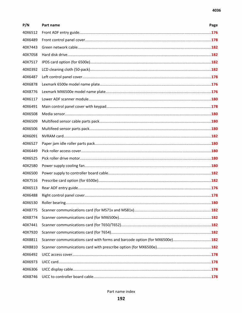
P/N Part name Page
40X6512 Front ADF entry guide............................................................................................................................176
40X6489 Front control panel cover.......................................................................................................................178
40X7443 Green network cable..............................................................................................................................182
40X7058 Hard disk drive.......................................................................................................................................182
40X7517 IPDS card option (for 6500e)..................................................................................................................182
40X0392 LCD cleaning cloth (50-pack)..................................................................................................................182
40X6487 Left control panel cover.........................................................................................................................178
40X6878 Lexmark 6500e model name plate.........................................................................................................176
40X8776 Lexmark MX6500e model name plate...................................................................................................176
40X6117 Lower ADF scanner module...................................................................................................................180
40X6491 Main control panel cover with keypad...................................................................................................178
40X6508 Media sensor..........................................................................................................................................180
40X6509 Multifeed sensor cable parts pack.........................................................................................................180
40X6506 Multifeed sensor parts pack...................................................................................................................180
40X6091 NVRAM card...........................................................................................................................................182
40X6527 Paper jam idle roller parts pack.............................................................................................................180
40X6449 Pick roller access cover...........................................................................................................................180
40X6525 Pick roller drive motor............................................................................................................................180
40X2580 Power supply cooling fan.......................................................................................................................180
40X6500 Power supply to controller board cable.................................................................................................182
40X7516 Prescribe card option (for 6500e)..........................................................................................................182
40X6513 Rear ADF entry guide.............................................................................................................................176
40X6488 Right control panel cover.......................................................................................................................178
40X6530 Roller bearing.........................................................................................................................................180
40X8775 Scanner communications card (for MS71x and MS81x)........................................................................182
40X8774 Scanner communications card (for MX6500e).......................................................................................182
40X7441 Scanner communications card (for T650/T652).....................................................................................182
40X7920 Scanner communications card (for T654)..............................................................................................182
40X8811 Scanner communications card with forms and barcode option (for MX6500e)....................................182
40X8810 Scanner communications card with prescribe option (for MX6500e)...................................................182
40X6492 UICC access cover...................................................................................................................................178
40X6973 UICC card................................................................................................................................................178
40X6306 UICC display cable..................................................................................................................................178
40X8746 UICC to controller board cable...............................................................................................................178
4036
Part name index
192

P/N Part name Page
40X6495 Universal power supply..........................................................................................................................182
40X6503 Upper ADF scanner module...................................................................................................................180
40X6493 USB cable parts pack..............................................................................................................................178
4036
Part name index
193

4036
Part name index
194