3g 05 oveview of wcdma
DESCRIPTION
wcdma conceptTRANSCRIPT
Wireless Information Transmission System Lab.
National Sun Yat-sen UniversityInstitute of Communications Engineering
WCDMA System Overview

2
Background and Standardization of WCDMA
WCDMA System Architecture
UTRAN (UMTS Terrestrial Radio Access Network) Architecture
3GPP TS 25.401
Table of Contents

Wireless Information Transmission System Lab.
National Sun Yat-sen UniversityInstitute of Communications Engineering
Background and Standardization of WCDMA

4
Since 1985, ITU (International Telecommunications Union) has been developing IMT-2000, previously termed Future Public Land Mobile Telephone System (FPLMTS).In 1992, the World Administrative Radio Conference (WARC) of the ITU identified the frequencies around 2 GHz for future 3rd generation mobile systems, both terrestrial and satellite.Within the ITU, the 3rd generation systems are called International Mobile Telephony 2000 (IMT-2000). In Europe, it is called UMTS (Universal Mobile Telephone Service).Original target: a single common global IMT-2000 air interface.Specification has been created in 3GPP (the 3rd Generation Partnership Project), which is the joint standardisation project of the standardisation bodies from Europe, Japan, Korea, the USA and China.
Air Interfaces for 3rd Generation Systems

5
Within 3GPP, WCDMA is called UTRA (Universal Terrestrial Radio Access) FDD and TDD.In addition to WCDMA, the other air interfaces that can be used to provide third generation services are EDGE and cdma2000.EDGE (Enhanced Data Rates for GSM Evolution) can provide third generation services with bit rates up to 500 kbps within aGSM carrier spacing of 200 kHz.EDGE includes advanced features that are not part of GSM to improve spectrum efficiency and to support the new services.cdma2000 can be used as an upgrade solution for the existing IS-95 operators.
Air Interfaces for 3rd Generation Systems
6
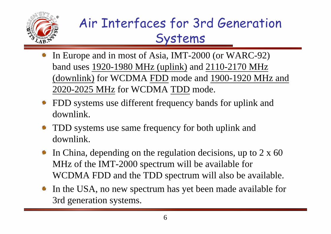
In Europe and in most of Asia, IMT-2000 (or WARC-92) band uses 1920-1980 MHz (uplink) and 2110-2170 MHz (downlink) for WCDMA FDD mode and 1900-1920 MHz and 2020-2025 MHz for WCDMA TDD mode.FDD systems use different frequency bands for uplink and downlink.TDD systems use same frequency for both uplink and downlink.In China, depending on the regulation decisions, up to 2 x 60 MHz of the IMT-2000 spectrum will be available for WCDMA FDD and the TDD spectrum will also be available.In the USA, no new spectrum has yet been made available for 3rd generation systems.
Air Interfaces for 3rd Generation Systems

7
2 GHz Band Spectrum Allocation

8
Europe
RACE I (Research of Advanced Communication Technologies in Europe) program started the basic 3rd generation research work in 1988.RACE II program develops the CDMA-based CODIT (Code Division Testbed) and TDMA-based ATDMA (Advanced TDMA Mobile Access) air interfaces during 1992-95.European research program ACTS (Advanced Communication Technologies and Services) was launched at the end of 1995 to support mobile communications research and development.Within ACTS, the FRAMES (Future Radio Wideband Multiple Access System) project was set up to define a proposal for a UMTS radio access system.
Nokia, Siemens, Ericsson, France Telecom, CSEM/Pro Telecom.

9
EuropeFRAMES wideband CDMA and wideband TDMA proposals were submitted to ETSI (European Telecommunications Standards Institute) as candidates for UMTS air interface and ITU IMT-2000 submission.After submission and presentation during 1996 and early 1997, proposals for the UMTS Terrestrial Radio Access (UTRA) air interface were grouped into five concept groups in ETSI in June 1997.
Wideband CDMA (WCDMA)Wideband TDMA (WTDMA)TDMA/CDMAOFDMAODMA
10
Europe
In January 1998, ETSI selects WCDMA as the standard for the UTRA (UMTS Terrestrial Radio Access) air interface on the paired frequency bands, i.e. for FDD (Frequency Division Duplexing) operation, and WTDMA/CDMA for operation with unpaired spectrum allocation, i.e. for TDD (Time Division Duplexing) operation.The detailed standardization of UTRA proceeded within ETSI until the work was handed over to the 3rd Generation Partnership Project (3GPP).The technical work was transferred to 3GPP with the contribution of UTRA in early 1999.
11
JapanARIB (the Association for Radio Industries and Businesses) was established in April 1993 to evaluate possible 3rd generation systems around three different main technologies based on WCDMA, WTDMA and OFDMA.The WCDMA technology in Japan was very similar to that being considered in Europe in ETSI.ARIB selected WCDMA, with both FDD and TDD modes operation, in 1997.WCDMA was chosen in ARIB before the process was completed in ETSI.ARIB contributed their WCDMA to 3GPP.

12
The United StatesMain standardization activities for wireless systems are carried out in TIA Engineering Committee TR45 and TR46, and in the T1 committee T1P1.TR45.5 is responsible for the IS-95, TR45.3 for the IS-136, and T1P1 with TR46 are jointly for GSM1900.Industry forums: UWCC for IS-136, CDMA Development Group (CDG) for IS-95, and the GSM Alliance and GSM North America for GSM.In April 1997, CDG issued the Advanced Systems initiative to develop the IS-95 based 3rd generation air interface proposal.In 1997, proposals from Hughes, Lucent, Motorola, Nokia, Nortel,Qualcomm, and Samsung, were submitted to TR45.5 for cdma2000, all backward compatible to IS-95.In March 1998, TR45.5 agreed on the basic framework for cdma2000: cdma2000 1x has same bandwidth as IS-95 (1.25 MHz) and cdma2000 3x, also called multicarrier CDMA, three times the bandwidth of IS-95.

13
KoreaTTA (Telecommunications Technology Association) adopted a two-track approach to the development of 3rd CDMA technology.ETRI established an R&D consortium to define the Korean proposal for IMT-2000 in 1997 and 1999.A wideband CDMA proposal has been developed within ETRI, which forms the basis for the TTA I scheme.SK Telecom (previously KMT, Korea Mobile Telecom) merged with other industrial proposals at the beginning of 1998 and formed the TTA II scheme.The TTA1 and TTA2 air interface proposals (later renamed Global CDMA 1 and 2) were based on synchronous and asynchronous wideband CDMA technologies respectively.Korean standardization efforts were later moved to 3GPP and 3GPP2 to contribute to WCDMA and cdma2000.
14
3GPP
3GPP (3rd Generation Partnership Project) was founded in 1998.The standardization organizations involved were ARIB (Japan), ETSI (Europe), TTA (Korea), TTC (Japan) and T1P1 (USA).The partners agreed on joint efforts for the standardization of UTRA, now standing for Universal Terrestrial Radio Access.In 1999, CWTS (the China Wireless Telecommunication Standard Group) joined 3GPP and contributed technology from TD-SCDMA, a TDD-based CDMA 3rd generation technology already submitted to ITU-R earlier.

15
3GPP
The first version of the common specification, called Release-99, was ready by the end of 1999.Within 3GPP, four different technical specification groups (TSG) were set up:
Radio Access Network (RAN) TSGCore Network TSGService and System Aspects TSGTerminals TSG
16
3GPP RAN TSG
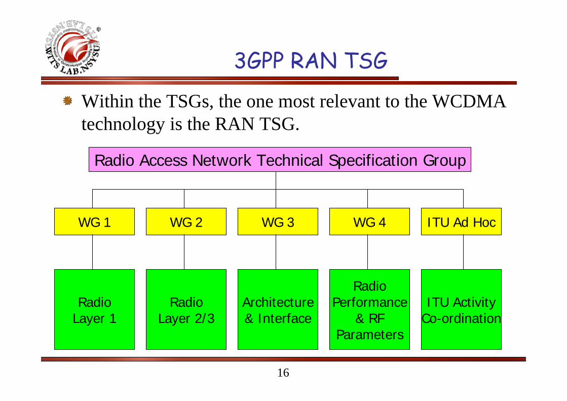
Within the TSGs, the one most relevant to the WCDMA technology is the RAN TSG.
Radio Access Network Technical Specification Group
ITU Ad HocWG 3 WG 4WG 2WG 1
RadioPerformance
& RFParameters
ITU ActivityCo-ordination
Architecture& Interface
RadioLayer 2/3
RadioLayer 1

17
3GPP2
Work done in TR45.5 and TTA was merged to form 3GPP2.Focused on cdma2000 Direct-Sequence (DS) and Multi-Carrier (MC) mode.This activity has been running in parallel with the 3GPP project, with participation from ARIB, TTC, and CWTS as member organizations.DS mode was abandoned.
18
Harmonization Phase
Manufacturers and operators agreed to adopt a harmonized global 3rd generation CDMA standard consisting of three modes: Multi-Carrier (MC) mode based on the cdma2000 multi-carrier option, Direct Spread (DS) mode on WCDMA (UTRA FDD), and the Time Division Duplex (TDD) mode on UTRA TDD.UTRA FDD and TDD mode chip rate were changed from 4.096 Mcps to 3.84 Mcps.

19
Parameters of WCDMA
Channel Bandwidth: 5 MHzDuplex Mode: FDD and TDDSpread Spectrum Technique: Direct SpreadChip Rate: 3.84 MHzFrame Length: 10 ms (38400 chips/sce)Slot Length: 15 Slots per Frame (2560 chips/slot)Spreading Modulation: Balanced QPSK (downlink) and Dual-Channel QPSK (uplink) with complex spreading circuit.Data Modulation: QPSK (downlink) and BPSK (uplink).
20
Parameters of WCDMAChannel Coding: Convolutional code, Turbo code, and no coding.Spreading Factors: 4-256 (uplink) and 4-512 (downlink).Modulation symbol rates vary from 960 k symbols/s to 15 k symbols/s (7.5 k symbols/s) for FDD uplink (downlink).Spreading (downlink): OVSF sequences for channel separation. Gold sequences 218-1 for cell and user separation (truncated cycle: 10 ms).Spreading (uplink): OVSF sequences for channel separation. Gold sequences 225-1 for user separation (truncated cycle: 10 ms).

21
WCDMA vs. GSM
Not supported by standard but can be applied
Supported for improving downlink capacity.
DL transmit diversity
Time slot based scheduling with GPRS
Load-based packet scheduling
Packet data
Frequency hopping.Multipath diversity with RAKE receiver
Frequency diversity
Network planning(frequency planning)
Radio resource management algorithm
Quality control
2 Hz or lower1.5 kHzPower control frequency
1-181Frequency reuse factor
200 kHz5 MHzCarrier spacing
GSMWCDMA

22
WCDMA vs. IS-95
Not supportedSupportedDL transmit diversity
Transmitted as short circuit-switched calls
Load-based packet scheduling
Packet data
Not needed for speech only network
Yes, provides required quality of service.
Radio resource management
Possible but not specifiedYesInter-frequency handover
Needed (typically GPS)Not neededBase station synchronization
UL: 800HzDL: slow control
1.5 kHz for both uplink and downlink.
Power control
1.2288 Mcps3.84 McpsChip rate
1.25 MHz5 MHzCarrier spacing
IS-95WCDMA

23
Core Network Relation to the 3rd Generation Air Interface Alternatives

Wireless Information Transmission System Lab.
National Sun Yat-sen UniversityInstitute of Communications Engineering
WCDMA System Architecture
25
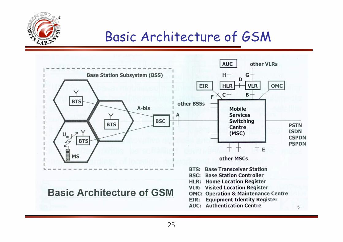
Basic Architecture of GSM

26
GSM Network Architecture
27
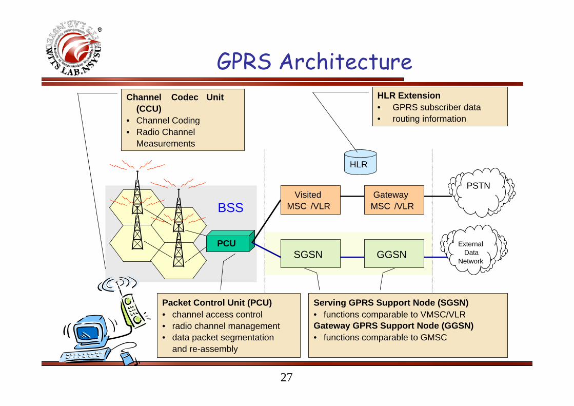
GPRS Architecture
PCU
BSS
Channel Codec Unit(CCU)
• Channel Coding• Radio Channel
Measurements
ExternalData
Network
VisitedMSC /VLR
GatewayMSC /VLR
HLR
SGSN GGSN
PSTN
HLR Extension• GPRS subscriber data• routing information
Packet Control Unit (PCU)• channel access control• radio channel management• data packet segmentation
and re-assembly
Serving GPRS Support Node (SGSN)• functions comparable to VMSC/VLRGateway GPRS Support Node (GGSN)• functions comparable to GMSC
28
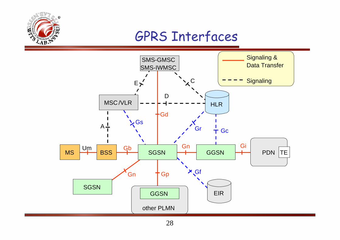
GPRS Interfaces
other PLMN
MSC /VLR HLR
EIR
SGSN
GGSN
GGSN
SGSN
PDN TE
SMS-GMSCSMS-IWMSC
MS BSSGiGn
Gn Gp
Gb
Gd
Um
GcGrGs
Gf
CE
D
A
Signaling & Data Transfer
Signaling

29
GPRS Transmission Planes
MAC
GSMRF
RLC
LLC
SNDCP
IP/X.25
MAC
GSMRF
RLC
FR
L1 bis
BSSGP
Relay
FR
L1 bis
BSSGP
LLC
SNDCP
L1
L2 L2
IP IP
UDP /TCP
UDP /TCP
GTP GTPRelay
IP/ X.25
MS BSS SGSN GGSNUm Gb Gn Gi
L1
BSSGP : BSS GPRS Protocol LLC : Logical Link Control SNDCP : SubNetwork DependentFR : Frame Relayl MAC : Medium Access Control Convergence ProtocolGTP : GPRS Tunnelling Protocol RLC : Radio Link Control TCP : Transmission Control Protocol IP : Internet Protocol UDP : User Datagram Protocol
L2‘
IP/X.25
L1‘
Relay
L2‘
IP/X.25
L1‘
L2‘
IP/X.25
L1‘
Relay
Application/ Higher level protocols
Router

30
GPRS Signaling Planes
L1
SCCPSignaling Conne -ction Control Part
TCAPTransactionCapabilities
Application Part
MAPMobile
ApplicationPart
MTP L2
MTP L3
L1
SCCP
TCAP
MAPMobile
ApplicationPart
MTP L2
MTP L3
L1
SCCP
MTP L2
MTP L3
L1
SCCP
MTP L2
MTP L3
BSSAP+BSSAP+
BSSApplication
Part +
SGSN HLR, EIR,SMS-GMSC
Gr ,f,d
SGSN MSC /VLRGsHLRGcGGSN
GPRS-specific
MAPextension
Subset ofBSSAPfunction-alities

31
UMTS Network Architecture

32
Network Elements in a WCDMA PLMNUu Iu
USIM
ME
Cu
UE
Node B
Node B
Node B
Node B
RNC
RNC
Iub Iur
UTRAN
MSC/VLR GMSC
SGSN GGSN
HLR
Core Network
PLMN, PSTNISDN, … etc.
Internet
ExternalNetworks
•PLMN: Public Land Mobile Network.•One PLMN is operated by a single operator.
33
User Equipment (UE)
The UE consists of two parts:The Mobile Equipment (ME) is the radio terminal used for radio communication over the Uu interface.The UMTS Subscriber Identity Module (USIM) is a smartcard that holds the subscriber identity, performs authentication algorithms, and stores authentication and encryption keys and some subscription information that is needed at the terminal.

34
UMTS Terrestrial Radio Access Network --UTRAN
UTRAN consists of two distinct elements:The Node B converts the data flow between the Iub and Uu interfaces. It also participates in radio resource management.The Radio Network Controller (RNC) owns and controls the radio resources in its domain (the Node Bs connected to it). RNC is the service access point for all services UTRAN provides the core network (CN).

35
WCDMA System Architecture
UMTS system utilizes the same well-known architecture that has been used by all main 2nd generation systems.The network elements are grouped into:
The Radio Access Network (RAN, UMTS Terrestrial RAN = UTRAN) that handles all radio-related functionality.The Core Network (CN) which is responsible for switching and routing calls and data connections to external networks.
Both User Equipment (UE) and UTRAN consist of completely new protocols, which is based on the new WCDMA radio technology.The definition of CN is adopted from GSM.
36
Main Elements of the GSM Core Network
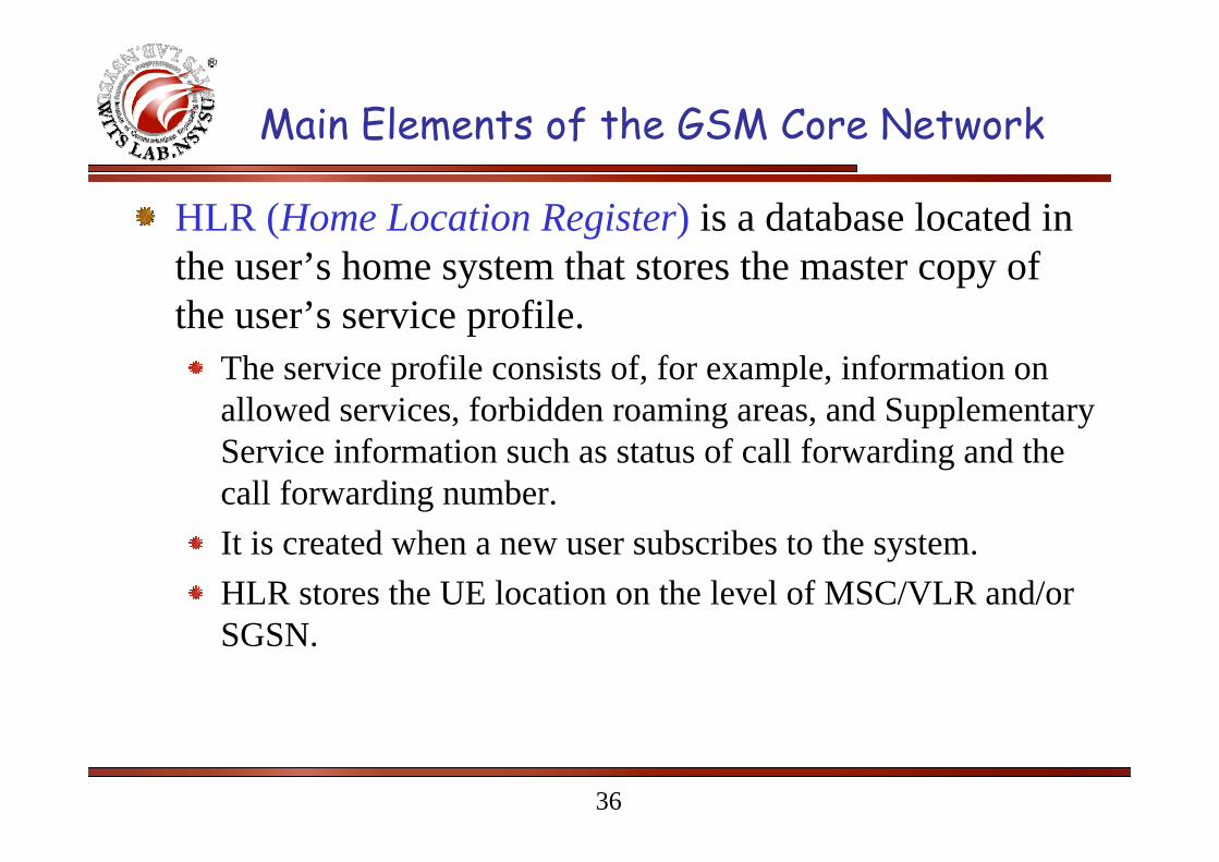
HLR (Home Location Register) is a database located in the user’s home system that stores the master copy of the user’s service profile.
The service profile consists of, for example, information on allowed services, forbidden roaming areas, and Supplementary Service information such as status of call forwarding and the call forwarding number.It is created when a new user subscribes to the system.HLR stores the UE location on the level of MSC/VLR and/or SGSN.
37
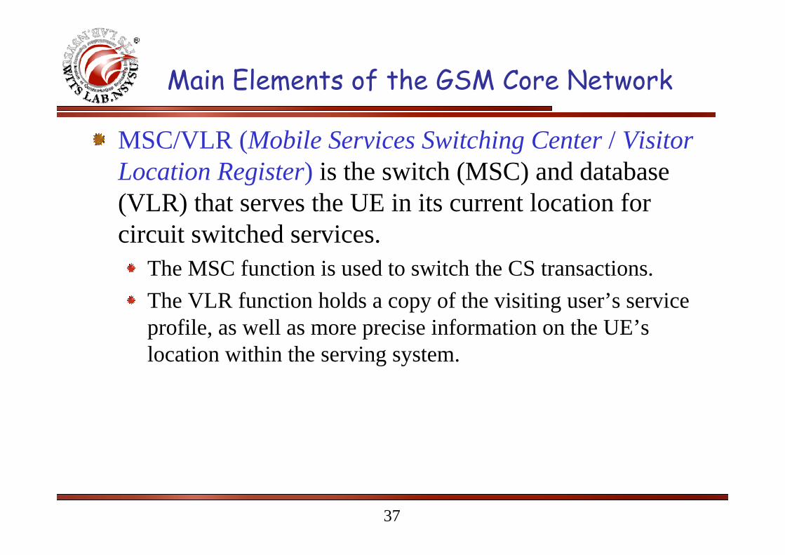
MSC/VLR (Mobile Services Switching Center / Visitor Location Register) is the switch (MSC) and database (VLR) that serves the UE in its current location for circuit switched services.
The MSC function is used to switch the CS transactions.The VLR function holds a copy of the visiting user’s service profile, as well as more precise information on the UE’slocation within the serving system.
Main Elements of the GSM Core Network

38
GMSC (Gateway MSC) is the switch at the point where UMTS PLMN is connected to external CS networks.
All incoming and outgoing circuit switched connections go through GMSC.
SGSN (Serving GPRS (General Packet Radio Service) Support Node) functionality is similar to that of MSC/VLR, but is typically used for Packet Switched (PS) services.GGSN (Gateway GPRS Support Node) functionality is close to that of GMSC but is in relation to PS services.
Main Elements of the GSM Core Network
39
InterfacesCu Interface: this is the electrical interface between the USIM smartcard and the ME. The interface follows a standard format for smartcards.Uu Interface: this is the WCDMA radio interface, which is the subject of the main part of WCDMA technology. This is also the most important open interface in UMTS.Iu Interface: this connects UTRAN to the CN.Iur Interface: the open Iur interface allows soft handover between RNCs from different manufacturers.Iub Interface: the Iub connects a Node B and an RNC. UMTS is the first commercial mobile telephony system where the Controller-Base Station interface is standardized as a fully open interface.
Wireless Information Transmission System Lab.
National Sun Yat-sen UniversityInstitute of Communications Engineering
UTRAN Overall Description
41
General Protocols Architecture
The protocols over Uu and Iu interfaces are divided into two structures:User plane protocols
These are the protocols implementing the actual radio access bearer service, i.e. carrying user data through the access stratum.
Control plane protocolsThese are the protocols for controlling the radio access bearers and the connection between the UE and the network from different aspects (including requesting the service, controlling different transmission resources, handover & streamlining etc.).

42
User PlaneThe radio access bearer service is offered from service access point (SAP) to SAP by the Access Stratum. The following figure shows the protocols on the Uu and Iu interfaces that link together to provide this radio access bearer service.
U T R A NU E C NA c c e s s S tra tu m
N o n -A c c e s s S tra tu m
R a d io(U u )
Iu
R a d iop ro to -c o ls(1 )
R a d iop ro to -c o ls(1 )
Iup ro toc o ls(2 )
Iup ro toc o ls(2 )
43
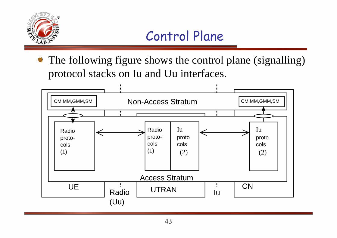
Control Plane
The following figure shows the control plane (signalling) protocol stacks on Iu and Uu interfaces.
UTRANUE CNAccess Stratum
Non-Access Stratum
Radio(Uu)
Iu
Radioproto-cols(1)
Radioproto-cols(1)
Iuprotocols(2)
Iuprotocols(2)
CM,MM,GMM,SM CM,MM,GMM,SM

44
UTRAN Architecture
RNS
RNC
RNS
RNC
Core Network
Node B Node B Node B Node B
Iu Iu
Iur
Iub IubIub Iub
UTRAN

45
UTRAN Architecture
UTRAN consists of one or more Radio Network Sub-systems (RNS), which are connected to the core network through the Iu.An RNS is a sub-network within UTRAN and consists of one Radio Network Controller (RNC) and one or more Node Bs.A Node B can support FDD mode, TDD mode, or dual-mode operation.RNCs may be connected to each other via Iur interface.

46
UTRAN Architecture
RNCs and Node Bs are connected with an Iubinterface.The RNC is responsible for the Handover decisions that require signaling to the UE.A RNC may include a combining/splitting function to support combination/splitting of information streams.Inside the UTRAN, the RNCs of the Radio Network Subsystems can be interconnected together through the Iur.

47
Main Characteristics of UTRAN
Support of UTRA and all the related functionalities.UTRAN has to support soft handover and the WCDMA-specific Radio Resource Management algorithms.
UTRA stands for UMTS Terrestrial Radio Access in ETSI and Universal Terrestrial Radio Access in 3GPP.
Maximization of the commonalities in the handling of packet-switched and circuit-switched data, with a unique air interface protocol stack.Use of the ATM transport as the main transport mechanism in UTRAN.
48
Radio Network Controller (RNC)
RNC is responsible for the control of the radio resources of UTRAN.
RNC interfaces with the core network (normally to one MSC and one SGSN).
RNC terminates the RRC (Radio Resource Control) protocol that defines the messages and procedures between the mobile and UTRAN.
RNC logically corresponds to the GSM BSC.

49
Logical Role of the RNC
Controlling RNC (CRNC): the RNC controlling a given Node B (i.e. terminating the Iub interface towards the Node B).
CRNC is responsible for the load and congestion control of its own cells.
CRNC executes the admission control and code allocation for new radio links to be established in those cells.
50
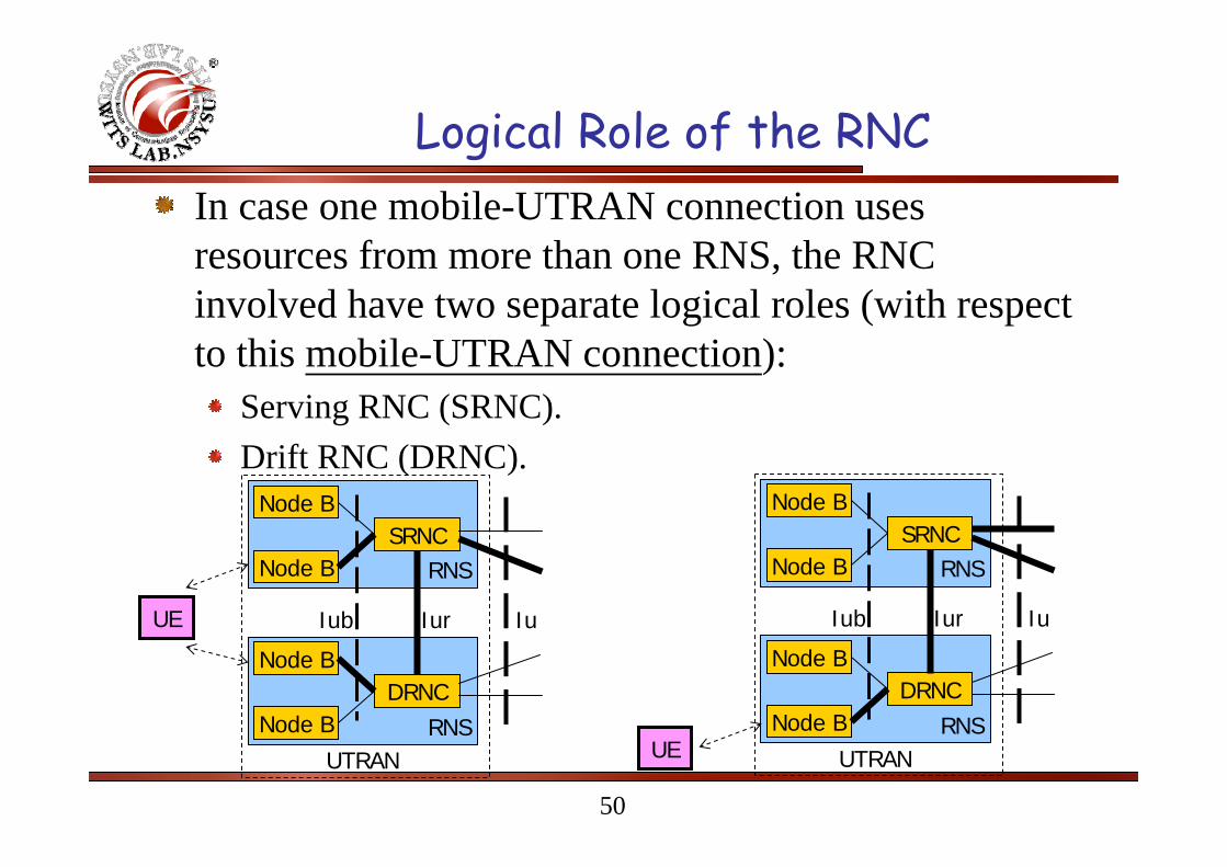
Logical Role of the RNCIn case one mobile-UTRAN connection uses resources from more than one RNS, the RNC involved have two separate logical roles (with respect to this mobile-UTRAN connection):
Serving RNC (SRNC).Drift RNC (DRNC).
Node B
Node BSRNC
Node B
Node BDRNC
Iub Iur
UTRAN
RNS
RNS
IuUE
Node B
Node BSRNC
Node B
Node BDRNC
Iub Iur
UTRAN
RNS
RNSUE
Iu
51
Serving RNC (SRNC)One UE connected to UTRAN has one and only oneSRNC.The SRNC for one mobile is the RNC that terminates both the Iu link for the transport of user data and the corresponding RANAP (RAN application part) signaling to/from the core network.SRNC also terminates the Radio Resource Control Signaling, that is the signaling protocol between the UE and UTRAN.SRNC executes basic Radio Resource Management operations, such as handover decision, outer loop power control, and the mapping of Radio Access Bearer parameters into air interface transport channel parameters.SRNC performs L2 processing of the data to/from the radio interface.

52
Drift RNC (DRNC)
One UE may have zero, one or more DRNCs.DRNC is any RNC, other than the SRNC, that controls cells used by the mobile.DRNC may perform macro-diversity combining.DRNC does not perform L2 processing of the user plane data.DRNC routes the data transparently between the Iuband Iur interface, except when the UE is using a common or shared transport channel.
53
UTRAN Functions List
Transfer of User DataRadio channel ciphering and decipheringIntegrity protection.Synchronization.Functions related to broadcast and multicast services.Overall system access control:
Admission Control.Congestion Control.System information broadcasting.

54
UTRAN Functions List
Functions related to mobility:Handover;SRNS Relocation;Paging support;Positioning.
Functions related to radio resource management and control:
Radio resource configuration and operation.Radio environment survey;Combining/splitting control.Connection set-up and release;
55
UTRAN Functions List
Functions related to radio resource management and control (continue):
Allocation and deallocation of Radio Bearers;Radio protocols function;RF power control.Radio channel coding;Channel coding control;Initial (random) access detection and handling.CN Distribution function for Non Access Stratum messages.

56
Serving RNS Relocation
SRNS
Core Network
Iu
DRNS Iur
UE
RNS
Core Network
Iu
SRNS
UE
After SRNS Relocation Before SRNS Relocation
Cells

57
Main Functions of Node B
Node B perform the air interface L1 processing (channel coding, interleaving, rate adaptation, spreading, modulation, … etc.).
Node B performs some basic Radio Resource Management operation such as inner loop power control.
Node B logically corresponds to the GSM Base Station.

58
Function Distribution Principles
For radio resource management functionality:The CRNC owns the radio resources of a cell.The SRNC handles the connection to one UE, and may borrow radio resources of a certain cell from the CRNC.Dynamical control of power for dedicated channels, within limits admitted by CRNC, is done by the SRNC.Dynamic control on smaller time-scale for some radio links of the UE connection may be done by the Node B. This "inner loop" control is controlled by an "outer loop", for which the SRNC has overall responsibility.Data scheduling for dedicated channels is done by the SRNC, while for common channels it is done by CRNC.

59
Function Distribution PrinciplesFor management of node-internal resources:
Each UTRAN node is considered a network element on its own. Theknowledge about the equipment of a network element is kept within the network element itself and its management system. The node itself always manages node-internal resources.
For transport network resource management:Management of transport network resources belong to the Transport Layer. Mechanisms relevant for the selected transport technology are used. No functional split between UTRAN nodes is specified whatregards the Transport Layer.
As a general guideline, the UTRAN protocols should be designed in such a way that they minimize the need for a DRNC to interpret the user plane frame protocol information other than for the combining/splitting purpose.

60
Mobility Management
All cell level mobility should be handled within UTRAN.The cell structure of the radio network should not necessarily be known outside the UTRAN.The UE may either have or not have a signaling connection:
When a signaling connection exists, the CN can reach the UE by the dedicated connection SAP on the CN side, and the UTRAN has a context with the UE and CN for this particular connection.When a dedicated connection does not exist, the CN must reach the UE via the Notification SAP. The message sent to the UE can be a request to the UE to establish a dedicated connection.

61
Mobility Management
When there is a signaling connection exists:Depending on the activity of a UE, the location of the UE is known either on cell level (higher activity) or in a larger areaconsisting of several cells (lower activity). This will
Minimize the number of location update messages for moving UEswith low activity.Remove the need for paging for UEs known on cell level.
The UTRAN shall handle the radio interface mobility of the UE, including procedures such as soft handover.

62
Mobility Management
Where there does not exist a dedicated connection between the UTRAN and the UE:
No UE information is needed in UTRAN.Mobility is handled directly between UE and CN outside access stratum (e.g. by means of registration procedure).When paging the UE, the CN indicates a ‘geographical area’that is translated within UTRAN to the actual cells that shall be paged.

63
Mobility Management
When a dedicated connection is released, the UE performs a new registration to the CN when needed.The UTRAN does not contain any permanent 'location registers' for the UE, but only temporary contexts for the duration of the dedicated connection.This context may typically contain location information (e.g. current cell(s) of the UE) and information about allocated radio resources and related connection references.

64
Synchronization
Different synchronization issues are identified within UTRAN:
1. Network Synchronisation;2. Node Synchronisation;3. Transport Channel synchronisation;4. Radio Interface Synchronisation;5. Time Alignment handling.

65
Synchronization Issues Model
TimeAlignmentHandling
TransportChannelSynchronisation
RadioInterfaceSynchronisation
NodeB
RNC
Vocoder
NodeB
NodeB
NodeB
NodeB
RNS
UTRAN
CN
UE 1 UE 2
RNC
Optional TDD only input &output sync ports
[TDD] RadioInterface
Sync.

66
Access Link Control Application Part: generic name for the transport signaling protocols used to set up and tear down transport bearers.
General Protocol Model for UTRAN Interface
The structure is based on the principle that the layers and planes are logicallyindependent of each other. Therefore, as and when required, the standardisationbody can easily alter protocol stacks and planes to fit future requirements.
ApplicationProtocol
DataStream(s)
ALCAP(s)
TransportNetwork
Layer
Physical Layer
SignallingBearer(s)
TransportUser
NetworkPlane
Control Plane User Plane
TransportUser
NetworkPlane
Transport NetworkControl Plane
RadioNetwork
Layer
SignallingBearer(s)
DataBearer(s)

67
The Protocol Structure consists of two main layers, Radio Network Layer, and Transport Network Layer.
All UTRAN related issues are visible only in the Radio Network Layer.
The Transport Network Layer represents standard transport technology that is selected to be used for UTRAN, but without any UTRAN specific requirements.
UTRAN Protocol Model – Horizontal Layers

68
Control Plane:The Control Plane includes the Application Protocol and the Signalling Bearer for transporting the Application Protocol messages.Among other things, the Application Protocol is used for setting up bearers for (i.e. Radio Access Bearer or Radio Link) in the Radio Network Layer. In the three plane structure the bearer parameters in the Application Protocol are not directly tied to the User Plane technology.The Signalling Bearer for the Application Protocol may or may not be of the same type as the Signalling Protocol for the ALCAP. The Signalling Bearer is always set up by O&M actions.
UTRAN Protocol Model – Vertical Planes
69
UTRAN Protocol Model – Vertical Planes
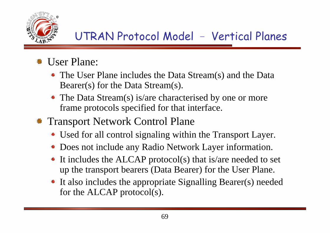
User Plane:The User Plane includes the Data Stream(s) and the Data Bearer(s) for the Data Stream(s).The Data Stream(s) is/are characterised by one or more frame protocols specified for that interface.
Transport Network Control PlaneUsed for all control signaling within the Transport Layer.Does not include any Radio Network Layer information.It includes the ALCAP protocol(s) that is/are needed to set up the transport bearers (Data Bearer) for the User Plane.It also includes the appropriate Signalling Bearer(s) needed for the ALCAP protocol(s).

70
UTRAN Protocol Model – Vertical Planes
Transport Network Control Plane: (continue)The Transport Network Control Plane is a plane that acts between the Control Plane and the User Plane.The introduction of Transport Network Control Plane makes it possible for the Application Protocol in the Radio Network Control Plane to be completely independent of the technology selected for Data Bearer in the User Plane.
71
UTRAN Protocol Model – Vertical Planes
Transport Network User PlaneThe Data Bearer(s) in the User Plane, and the Signalling Bearer(s) for Application Protocol, belong also to Transport Network User Plane.The Data Bearers in Transport Network User Plane are directly controlled by Transport Network Control Plane during real time operation, but the control actions required for setting up the Signalling Bearer(s) for Application Protocol are considered O&M actions.