3d computerized model for measuring strain and ... · brachial plexus 3d model currently can be...
TRANSCRIPT

3D Computerized Model for MeasuringStrain and Displacement of the BrachialPlexus Following Placement of Reverse
Shoulder ProsthesisTOM VAN HOOF,1* GERMANO T. GOMES,1 EMMANUEL AUDENAERT,2
KOENRAAD VERSTRAETE,3 INGRID KERCKAERT,1 AND KATHARINA D’HERDE1
1Department of Human Anatomy, Embryology, Histology and Medical Physics,University of Ghent, Ghent, Belgium
2Department of Physical Medicine and Rehabilitation,University of Ghent, Ghent, Belgium
3Department of Radiology, University of Ghent, Ghent, Belgium
ABSTRACTThe aim of the present study was to develop a method for three-
dimensional (3D) reconstruction of the brachial plexus to study its mor-phology and to calculate strain and displacement in relation to changednerve position. The brachial plexus was finely dissected and injected withcontrast medium and leaden markers were implanted into the nerves atpredefined places. A reverse shoulder prosthesis was inserted in a cadav-eric specimen what induced positional change in the upper limb nerves.Computed tomography (CT) was performed before and after this surgicalintervention. The computer assisted image processing package Mimics1
was used to reconstruct the pre- and postoperative brachial plexus in 3D.The results show that the current interactive model is a realistic anddetailed representation of the specimen used, which allows 3D study ofthe brachial plexus in different configurations. The model estimatedstrains up to 15.3% and 19.3% for the lateral and the medial root of themedian nerve as a consequence of placing a reverse shoulder prosthesis.Furthermore, the model succeeded in calculating the displacement of thebrachial plexus by tracking each implanted lead marker. The presentedbrachial plexus 3D model currently can be used in vitro for cadaver bio-mechanical analyses of nerve movement to improve diagnosis and treat-ment of peripheral neuropathies. The model can also be applied to studythe exact location of the plexus in unusual upper limb positions like dur-ing axillary radiation therapy and it is a potential tool to optimize theapproaches of brachial plexus anesthetic blocks. Anat Rec, 291:1173–1185, 2008. � 2008 Wiley-Liss, Inc.
Key words: anatomic models; brachial plexus; biomechanics;computer assisted image processing
It is generally accepted that impaired nerve movementcan lead to nerve injury (McLellan, 1975; McLellan andSwash, 1976). In the past decades, different techniques,e.g., speckle tracking and Doppler ultrasonography, weredeveloped allowing to infer tissue motion and to esti-mate strain (Hough et al., 2000; Dilley et al., 2001). Yetto investigate movement of morphological complex nervestructures, there is a need for exact three-dimensional
*Correspondence to: Tom Van Hoof, De Pintelaan 185, 4B3,B-9000 Ghent, Belgium. Fax 32-9240-3809.E-mail: [email protected]
Received 24 January 2008; Accepted 24 April 2008
DOI 10.1002/ar.20735Published online 5 June 2008 in Wiley InterScience (www.interscience.wiley.com).
� 2008 WILEY-LISS, INC.
THE ANATOMICAL RECORD 291:1173–1185 (2008)

(3D) approaches and computer simulation (Lien et al.,2005). With modern radiographical 2D techniques, itremains difficult to depict detailed anatomy of the brach-ial plexus and there is few information concerning thetopography of the plexus in extraordinary postures ofthe upper limb. Advanced 3D visualization and measure-ment techniques are needed to clarify problems in regionswith complex anatomic organization. In this study, wepresent a method to create a 3D model of the cadavericbrachial plexus allowing detailed study of its morphologyand its biomechanical behavior after the surgical proce-dure of placing a reverse shoulder prosthesis.Abnormal nerve movement can cause peripheral neu-
rological disorders such as thoracic outlet syndrome(TOS) and carpal tunnel syndrome (CTS). Reducedtransverse movement of the median nerve has beenobserved in both subjects with CTS (Nakamichi andTachibana, 1995; Allmann et al., 1997; Hough et al.,2007) and nonspecific arm pain (Greening et al., 1999,2001). Julius et al. (2004) found by means of ultrasoundmeasurements, that shoulder protraction restricts me-dian nerve sliding through the shoulder region up to60%. They conclude that sustained shoulder protractionmay place the median nerve at enhanced risk of injuryand possibly can cause a neurovascular compromise.Nevertheless, they were unable to establish or visualizethe precise cause of the entrapment because of therestrictions of ultrasound measurement techniqueswhen applied to a movement in a complex joint withmany different interplaying hard and soft tissues.Another example is the field of TOS and particularly
these forms that are strongly related to poor postureand predisposing morphotype in the absence of anatomi-cal anomalies. Demondion et al. (2000) stated that acomplete understanding of the normal relationshipbetween the components of the thoracic outlet and theneurovascular bundle is essential for interpreting signsof compression in TOS. They reported on compressionand dynamic modifications of the thoracic outlet in asso-ciation with postural manoeuvres by means of magneticresonance imaging (MRI) and color duplex ultrasonogra-phy (Demondion et al., 2003, 2006). Patients with TOShad a smaller costoclavicular distance around the brach-ial plexus after hyperabduction. They also concludedthat ultrasonography should not be used solely but as asupplementary technique to computed tomography (CT)or MRI because it does not allow an accurate overviewof the thoracic outlet region (Demondion et al., 2003,2006). The disadvantage of planar CT or MRI is that 2Dimages only allow interpretation in one plane at thetime. Consequently, these studies of Demondion et al.,(2000, 2003, 2006) were mainly focused on compression,when stretch (strain) of the brachial plexus may playanother important role in the etiology of TOS.Swift and Nichols (1984) reported on patients with
TOS presenting with a droopy shoulder syndrome andsuggested that their symptoms resulted from stretchingof the brachial plexus. Ide et al. (2003) distinguished twomain categories of TOS. They found that 92% of the 150patients examined, had neuroradiographic evidence ofcompression of the brachial plexus in the costoclavicularspace and 82% had neuroradiographic evidence of stretch-ing the brachial plexus. Even though it concerned aradiologic study, no details were obtained about amountand exact location of the neural stretch in the plexus.
Detailed anatomical descriptions and imaging studiesof the brachial plexus with the upper limb and/or cervi-cal spine in an unusual non-neutral posture are scarce.These are of clinical interest for radiotherapists who aremainly concerned about the exact location of the brach-ial plexus in the ‘‘arms up over the head’’ positionrequired for axillary radiation, in an attempt to increasetissue selectivity and minimize the hazard of radiation-induced brachial plexopathy (Cash et al., 2005). Theexact topography of the plexus and its displacement as aconsequence of positioning the patient is also of interestto anesthesiologists in search of a safer and more accu-rate approach for plexus block anesthesia.It is generally known that 3D models serve better for
anatomical perception of complex structures, when com-pared with classic plane views. In 2D radiological sectionsit is up to the viewer to mentally reconstruct the struc-tures; the quality of this process depends on the power ofthe observer’s imagination (Tomandl et al., 2001; Naraghiet al., 2004; Spinner et al., 2006). Therefore, there is needfor 3D models which should allow quantitative interpreta-tion of anatomical and biomechanical aspects of the entireplexus in all three dimensions. The purpose of the pres-ent research is to develop a method for 3D reconstructionof the brachial plexus to study its morphology in differentpostures and to measure strain (elongation) and displace-ment of the plexus caused by procedures influencing theupper limb nerve position, in this study realized by plac-ing a reverse shoulder prosthesis.
METHODS
Subjects
Initially, we used a specimen (male, 69 years)embalmed according to the Thiel method (Thiel, 1992)because it preserves the cadaver without stiffeningwhich represents a major advantage in a biomechanicalstudy. However, tissue solidity proved to be insufficientto sustain properly the surgical procedure of prosthesisinsertion. Therefore the only remaining purpose of thatcadaver was to elaborate the methodology: we tested theprocedure of identifying the different components of theplexus on CT scans after subepineural injection of con-trast medium and the feasibility to mark fixed points ofthe plexus by grafting of lead markers.A second cadaver (female, 94 years; time between
embalming and use: 3 months) embalmed according toour routine procedure (De Maeseneer et al., 2003) wasthen used for the complete process of brachial plexuspreparation, segmentation, 3D reconstruction, prosthesisplacement, and measurement.
Procedure
The brachial plexus was carefully dissected from itspassage through the interscalene triangle up to theproximal part of the peripheral nerves and local topogra-phy was maintained as much as possible. Dissection wascontinued until all parts were accessible with an injec-tion needle. The clavicle and pectoralis minor musclewere preserved, the pectoralis major muscle was sec-tioned at its tendon of insertion and later on reinsertedbefore skin closure.The brachial plexus was injected with a mixture
iodium contrast (Visipaque1) with 33% glycerin and
1174 VAN HOOF ET AL.

0.075% toluidine blue (Pfirrmann et al., 2001; Feiglet al., 2006). Glycerin increases the viscosity of the mix-ture (Pfirrmann et al., 2001), the addition of the tolui-dine blue allows a visual control over dispersion andpossible leakage of the mixture. The needle (Terumo1
needle 0.45 3 23 mm) was inserted under the epineu-rium (Demondion et al., 2005) of the nervous tissue, andthe solution was injected with mild pressure until leak-age occurred at the injection site or at spots furtheraway along the nerve segment. The injection sites weredistributed along the entire course of the brachial plexuswith a mean intermediate distance of approximately3 cm, depending on the absorbing capacity of the regard-ing segment.Subsequently 16 lead beads (lead [Pb] fishing weights,
Dinsmores1 3 mm) were implanted into the nerves atpredefined places; start of the divisions (3), start of thecords (2), start of the peripheral nerves (4), peripheralnerves at mid-humeral level (3), peripheral nerves atelbow level (3), and one at the end of the axillary nerve.After the first session of CT scanning (see below) the
specimen returned to the cadaver lab and a plastic rep-lica of a reverse shoulder prosthesis was insertedfollowed by re-injection of the plexus with the same so-lution. The reverse shoulder prosthesis was placedaccording to the guidelines of the American Academy ofOrthopaedic Surgeons (Matsen et al., 2007). Subse-quently, the specimen was scanned with the upper limbin a different position as a consequence of the surgicalintervention, that is, insertion of the reverse shoulderprosthesis, further referred to as postoperative. The ini-tial CT scans taken before the surgical interventionand the results originating from it, will be referred toas preoperative.It should be stressed that this study was not focused
on the shoulder prosthesis itself: Rather the initial con-cept of measuring alterations in nerve position was sub-jected to a clinically relevant situation, that is, surgicalprocedure of placing a reverse shoulder prosthesis to de-velop a generally applicable 3D model for estimating dis-placement and strain of the brachial plexus.
CT Scanning
The preoperative and postoperative specimens werestudied by a helical CT scan (Siemens/ volume zoom).Scanning parameters were 120 KV, 165 mas, slice incre-ment 1 mm, field of view 480 mm, and 512 3 512 pixels(0.938 mm pixel size).The shoulder of the specimen was positioned in adduc-
tion internal rotation and the elbow in approximately908 flexion. The cervical spine was positioned in neutralposition and both wrists were placed and strapped downon the lower abdomen.The CT images of the first and the second session
were uploaded separately into a software package thatcan import any 2D stack of images (e.g., CT and MRI)and allows 3D reconstruction. In the present studyMimics1 (Materialise N.V., Heverlee, Belgium) was usedfor visualization and segmentation of CT images and 3Drendering of the brachial plexus with a direct link to bio-mechanical analysis of nerve strain (elongation) and dis-placement.Thresholding was the first action performed to create
a segmentation mask. We selected the region of interest,
that is, brachial plexus with contrast, by defining itsspecific range of gray values. Subsequently, we per-formed a ‘‘dynamic region growing,’’ a procedure thatsegments objects based on the connectivity of gray val-ues in a certain gray value range. This procedure allowsfor segmentation of nerves in CT images. This approachwas repeated for all bones of the upper quadrant andthe lead markers implanted in the nerves. Further man-ual adjusting was performed to eliminate errors origi-nating from the semi automatic reconstruction phase.
Measurements
In Mimics, each lead marker in the 3D model wasindicated by a virtual tag by means of the ‘‘measure andanalyze’’ tool. Virtual tags were also placed on prede-fined positions of each part of the brachial plexus (Fig.1A,B). This procedure was repeated for the pre- and thepostoperative project.Thereafter the virtual tags were exported as text files
which allowed to obtain the corresponding coordinates(x,y,z) of these points, which were set relative to thecoordinate system inherent to the Mimics software pro-gram itself. The text files containing the coordinateswere then imported into Matlab1 (Mathworks, Inc.,Natick, MA) where a customized algorithm calculatedthe best fitting curve (i.e., smooth spline) in a way thatit approached the real path of the nerves as much aspossible.The distance between two successive lead markers cal-
culated along the path of the nerve produced the reallength of that particular segment. The shortest distance(i.e., straight line) between two successive lead markerswas also calculated and is referred to as vector length.In Matlab, the different coordinate system of the post-
operative brachial plexus was transformed (i.e., trans-lated and rotated) into the same coordinate system ofthe preoperative brachial plexus. To achieve that, sup-plementary virtual tags were placed at each interverte-bral foramina (C5–T1) and at the bifurcation of the xiph-oid process, identically for both the pre- and the postop-erative project. Matlab then calculated the rigid bodytransformation matrix providing the best fit, in a leastsquares sense, between these pairs of reference pointsand subsequently transformed the postoperative into thepreoperative project.This alignment was performed to allow calculation of
the displacement of each lead marker inside the brachialplexus as a result of positional change of the neural tis-sue caused by placing the reverse prosthesis. This dis-placement is calculated as the shortest distance (straightline) between the pre- and postoperative position of themarker.The transformation was also performed in Mimics to
visualize the pre- and postoperative plexus in the samecoordinate system. The reference points of two interver-tebral foramina (C5 an C8) and the xiphoid processbifurcation were incorporated in the mask of the brach-ial plexus followed by a recalculation of the 3D object.The marking of these bony reference points resulted inthe appearance of three additional points in the 3Dmodel representing these specific anatomical locations.This procedure was performed for both the pre- andpostoperative project. Then the postoperative 3D objectwas saved in the STL format (Stereolithography, simple
1175INTERACTIVE 3D MODEL OF THE BRACHIAL PLEXUS

output format of Computer Aided Design systems) andimported into the preoperative project were it becamevisible but not aligned with the preoperative plexus.Using the ‘‘point registration’’ tool in Mimics, the corre-sponding reference points were selected and aligned in amanner similar to the procedure in Matlab.
Data Collection
We measured real length of each nerve segmentbetween subsequent lead markers, and vector length asthe straight distance between the lead markers. Thereal length of each nerve segment in the preoperativeproject is assumed as the normal not-elongated referencelength. The formula (lrPost–lrPre)/lrPre 3 100% allows tocalculate strain (or shortening) of a nerve segment bysubstituting its pre- and postoperative real length(respectively, lrPre and lrPost).The amount of coiling or curve was estimated by the
ratio of vector length to real length through the formula(lv–lr)/lr 3 100% with lv as the vector length and lr asthe real length, resulting in a negative value. No coilingoccurs when both lengths equal (0%) and when forexample the vector length is 4/5 of the real length, 20%of coiling is expressed by the formula as 220%. If post-operatively the real length of the nerve segment isincreased (strain), this inevitably implicates that the coilof the neural tissue is completely taken up. If in this sit-uation still a negative ratio is obtained [(lv–lr)/lr 3100%], this means that the nerve follows a curvedcourse what is also characterized by the real lengthbeing longer that the vector length.
Finally, the absolute displacement of one and thesame lead marker between the pre- and postoperativesituation was also calculated as a vector length (shortestdistance).The mean error (error1) of placing the virtual tags in
the lead markers and the circular 95% confidence inter-val were calculated. This procedure had to be consideredtwo times because length is determined between two vir-tual markers: we used the upper limit as a critical valuefor the differences in length of the nerve segments (2error1 1 1.96 (SE2 1 SE2)1/2 5 0.87 mm). Differencessmaller than 0.87 mm were attributed to random noiseand are bellow the resolution of this method and are notconsidered for the strain calculation.To assess significant displacement of each lead marker
between the pre- and postoperative situation, a secondcritical value was calculated as the summation of thefirst error (error1) of placing the virtual tags and a sec-ond error (error2) inherent in the transformation processof the coordinate system of the postoperative plexus.This resulted in 1.89 mm (2 error1 1 error2 1 1.96 (SE1
2
1 SE12 1 SE2
2)1/2 5 1.89 mm); the distance between thepre- and postoperative position of a particular leadmarker (in the same coordinate system) has to exceedthis critical value to be determined as a significant dis-placement.
RESULTS
Figure 2A–D illustrates that the anatomical details ofthe cadaveric brachial plexus are also depicted in thereconstructed plexus. Figure 2B shows the crossing ofthe lateral root of the median nerve over the axillary ar-
Fig. 1. Illustration of the placing of virtual tags (red dots) in the lat-eral root of the median nerve. A: The preoperative plexus in purple;the blue beads represent the lead markers; this image clearly demon-strates that the initial and final virtual tags coincide respectively withthe lead markers that indicate the start and the end of the regardingnerve segment (the initial virtual tag is indicated by the black arrow;
the final virtual tag is represented by the little green dot in the bluelead marker indicating the end of the lateral root of median nerve). B:The postoperative plexus in yellow; the gray beads represent the leadmarkers; the little green dot indicates the final virtual tag coincidingwith the lead marker distally delimiting the nerve segment; the initialvirtual tag is also indicated by the black arrow.
1176 VAN HOOF ET AL.

tery and the subsequent drop posteriorly, which isclearly visible in corresponding cadaveric picture(Fig. 2A).Of interest, the cadaveric brachial plexus displays an
anatomical variant: there is a second smaller lateralroot of the median nerve—area between black lines(Fig. 2A)—that parallels the original one medially andalso crosses the axillary artery. The medial cutaneousnerves of the arm and the forearm are situated betweenboth white lines (Fig. 2A). These cutaneous nerves andthe surnummerary lateral root of the median nerve(Fig. 2A) were not injected with contrast fluid and as aconsequence were not depicted in the 3D model (Fig.2B). The fact that these noninjected nervous structures,as well as the axillary artery, appear pale blue is due todiffusion of contrast fluid. It should be noted that thisdissection, to illustrate the morphology of the plexus indetail, was performed several days after the scanningprocedure.To improve identification of the different components
of the plexus in Figure 2C, the anterior division of the
superior trunk and the lateral cord were lifted, exposingthe posterior division of the superior trunk. The dissec-tion in the axilla (Fig. 2A) could only be performed if theshoulder was slightly externally rotated and abducted ascompared to its position during scanning. The differentpositioning of the cadaver during dissection and scan-ning (shoulder slightly adducted and internally rotated)can explain the minor positional divergencies betweenthe original cadaveric and the reconstructed plexus.Notably, there is the increased curvature of the ulnarnerve and the changed orientation of the musculocuta-neous nerve (Fig. 2B).
Measurements
Figures 3 and 4 illustrate the reconstructed plexus inrelation to the cervical spine, the first rib, the bones ofthe shoulder girdle, and the subclavian/axillary artery.Figure 5A shows the distal movement of the postopera-tive humerus (light gray). The postoperative humerus isslightly flexed posteriorly (retroflexed) and externally
Fig. 2. A–D: Comparison between the dissected brachial plexus(A,C) and the 3D reconstructed plexus (B,D) shows structural confor-mity: A,B infraclavicular level and C,D level of the divisions. A,B: aa,axillary artery; lc, lateral cord; mc, medial cord; lr, lateral root of themedian nerve; mr, medial root of the median nerve; mn, median nerve;mcn, musculocutaneous nerve; rn, radial nerve; un, ulnar nerve. A:Area between yellow dots represents common trunk of the medialcord bifurcating into medial root of median nerve above double yellowline and ulnar nerve below; area between white lines representsmedial cutaneous nerve of the arm and forearm; area between black
lines represents surnummerary lateral root of median nerve. C,D: st,superior trunk; mt, middle trunk; it, inferior trunk; ads, anterior divisionof superior trunk; adm, anterior division of middle trunk; pd, posteriordivision of superior trunk; lc, lateral cord; mc, medial cord; pc, poste-rior cord; sa, subclavian artery. C: White open arrow, posterior divisionof middle trunk, white arrow, posterior division of inferior trunk. D:white arrow heads, posterior division of superior trunk; white openarrow, posterior division of middle trunk; white arrow, posterior divisionof inferior trunk. The subclavian artery is left out of the reconstructionfor illustrative reasons.
1177INTERACTIVE 3D MODEL OF THE BRACHIAL PLEXUS

rotated in comparison to the preoperative situation (Fig.5A–C).In this section, only the results concerning the distal
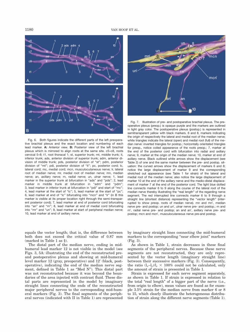
part of the plexus are described. The results for theproximal part are summarized in Table 3 and can befound in the appendix. Figure 6A,B provides an over-view of the location of the different lead markers divid-ing the brachial plexus in different nerve segments.Figures 3 and 7 show the convoluted course for both
the lateral and the medial root of the median nerve pre-operatively. This is in accordance with the correspondingratios determining 219.3% coil for the lateral and217.1% coil for the medial root as demonstrated inTable 1.
In the lateral root of the median nerve, 15.3% strainis recorded postoperatively due to the distal displace-ment of the humerus. In the medial root of the mediannerve, strain up to 19.3% is found (Table 1; Fig. 7).Accordingly, Figures 4 and 7 show that postoperativelythis convoluted course is completely straightened out.Despite this, Table 1 still indicates negative ratio values(nerve topology) for the regarding segments postopera-tively, to be precise 27.3% for the lateral and 27.5% forthe medial root. These negative values, cannot implicatecoil because the concerning parts are strained meaningthat the coil inevitably is taken up. Figure 7 illustratespostoperatively (in yellow) the curved course (represent-ing real length) of the lateral and medial root of the me-dian nerve in comparison to the straight vector lengthwhich explains these negative values. The real length ofthe lateral root of the median nerve is demonstrated bythe light blue dotted line along the curved course of thisnerve segment (extending) from marker 6 to 9 in com-parison with the interrupted red line representing thevector length as the straight distance between the samemarkers (Fig. 7).The preoperative median nerve (segment from marker
9 to 12; Fig. 3) was found to be coiled 22.2%, and afterthe surgical procedure, it was strained for 2.9% (Ta-ble 1). Postoperatively, this nerve segment is not curvedbut just follows a straight course as indicated by the 0%ratio, which is a result of the fact that the real length
Fig. 3. Preoperative: Overview of the cervical spine and posteriorpart of the first rib (gray); clavicle (cl), scapula and the semi-transpar-ent humerus (brown); brachial plexus (purple) and axillary artery (aa)(red). Preoperative markers (light gray) of the nonreconstructed periph-eral nerves at mid-humeral level: 11, marker of radial nerve behind hu-merus; 12, marker of median nerve; 13, marker of ulnar nerve and at‘‘near elbow’’ level: 14, marker of radial nerve; 15, marker of mediannerve; 16, marker of ulnar nerve behind the medial epicondyle. Mediannerve from marker 9 to 12; ulnar nerve from marker 8 to 13; radialnerve from marker 7 to 11: the nonreconstructed parts of these nerves(distal from inset) extend from the end of the visible peripheral nerve(purple) to the corresponding mid-humeral marker represented in themodel by an imaginary straight line. Median nerve II, ulnar nerve II andradial nerve II: imaginary straight lines connecting respectively markers12–15, 13–16 and 11–14 according to the segments used in Table 1.Inset shows the preoperative brachial plexus (purple) and axillary ar-tery (aa) in detail. Notice the coiled appearance of the brachial plexusdistal from the coracoid process (cp). cl, clavicle; contours of posteriorpart of first rib (dark gray) appear in the sternal facet of the semi-transparent clavicle just below aa; lr, lateral root of the median nerve:mr, medial root of the medial nerve; mn, median nerve; un, ulnarnerve; rn, radial nerve; an, axillary nerve with gray marker 10 at theend behind humerus; open white inversed triangle, lateral cord; fullwhite arrowhead, medial cord; open white arrowhead, posterior cord;6, marker at the end of lateral cord indicating bifurcation of lr and themusculocutaneous nerve (stump with craniolateral orientation); 8,marker at the end of medial cord indicating bifurcation of mr and un;9, marker indicating the start of mn; full white triangle, bicipital grooveof humerus flanked medially by the lesser tubercle and laterally by thegreater tubercle.
Fig. 4. Postoperative: Overview of the cervical spine and posteriorpart of the first rib (r1) (dark gray); clavicle (cl), scapula and humerus(light gray), brachial plexus (yellow) and axillary artery (aa) (red). Noticethe reverse shoulder prosthesis with the glenosphere (gs) inserted intoglenoid cavity and the epiphyse (ep) part inserted into the humeralshaft. Also notice the straightened out appearance of the postopera-tive brachial plexus in comparison to Figure 3 preoperatively. c5–c8,roots c5–c8; mn, median nerve; rn, radial nerve; an, axillary nerve; cp,coracoid process; ac, acromioclavicular joint; 30, marker in inferiortrunk at bifurcation of posterior division and medial cord; 40, marker atstart of lateral cord; 60, marker at the end of lateral cord indicatingbifurcation of lateral root median nerve and the musculocutaneousnerve (notice the changed orientation of the latter); 70, marker at endof posterior cord indicating bifurcation in ‘‘an’’ and ‘‘rn’’; 90, marker atstart of median nerve; 100, marker at end of axillary nerve.
1178 VAN HOOF ET AL.
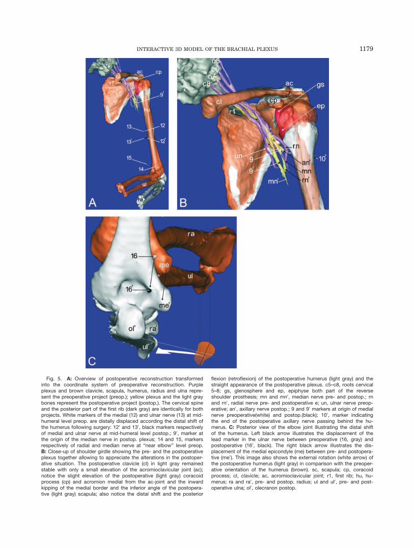
Fig. 5. A: Overview of postoperative reconstruction transformedinto the coordinate system of preoperative reconstruction. Purpleplexus and brown clavicle, scapula, humerus, radius and ulna repre-sent the preoperative project (preop.); yellow plexus and the light graybones represent the postoperative project (postop.). The cervical spineand the posterior part of the first rib (dark gray) are identically for bothprojects. White markers of the medial (12) and ulnar nerve (13) at mid-humeral level preop. are distally displaced according the distal shift ofthe humerus following surgery: 120 and 130, black markers respectivelyof medial and ulnar nerve at mid-humeral level postop.; 90, marker atthe origin of the median nerve in postop. plexus; 14 and 15, markersrespectively of radial and median nerve at ‘‘near elbow’’ level preop.B: Close-up of shoulder girdle showing the pre- and the postoperativeplexus together allowing to appreciate the alterations in the postoper-ative situation. The postoperative clavicle (cl) in light gray remainedstable with only a small elevation of the acromioclavicular joint (ac);notice the slight elevation of the postoperative (light gray) coracoidprocess (cp) and acromion medial from the ac-joint and the inwardkipping of the medial border and the inferior angle of the postopera-tive (light gray) scapula; also notice the distal shift and the posterior
flexion (retroflexion) of the postoperative humerus (light gray) and thestraight appearance of the postoperative plexus. c5–c8, roots cervical5–8; gs, glenosphere and ep, epiphyse both part of the reverseshoulder prosthesis; mn and mn0, median nerve pre- and postop.; rnand rn0, radial nerve pre- and postoperative e; un, ulnar nerve preop-erative; an0, axillary nerve postop.; 9 and 90 markers at origin of medialnerve preoperative(white) and postop.(black); 100, marker indicatingthe end of the postoperative axillary nerve passing behind the hu-merus. C: Posterior view of the elbow joint illustrating the distal shiftof the humerus. Left black arrow illustrates the displacement of thelead marker in the ulnar nerve between preoperative (16, gray) andpostoperative (160, black). The right black arrow illustrates the dis-placement of the medial epicondyle (me) between pre- and postopera-tive (me0). This image also shows the external rotation (white arrow) ofthe postoperative humerus (light gray) in comparison with the preoper-ative orientation of the humerus (brown). sc, scapula; cp, coracoidprocess; cl, clavicle; ac, acromioclavicular joint; r1, first rib; hu, hu-merus; ra and ra0, pre- and postop. radius; ul and ul0, pre- and post-operative ulna; ol0, olecranon postop.
1179INTERACTIVE 3D MODEL OF THE BRACHIAL PLEXUS
equals the vector length; that is, the difference betweenboth does not exceed the critical value of 0.87 mm(marked in Table 1 as §).The distal part of the median nerve, ending in mid-
humeral lead marker 12 is not visible in the model (seeFigs. 3, 5A: illustrating the end of the reconstructed pre-and postoperative plexus and showing at mid-humerallevel marker 12 (gray, preoperative) and 120 (black, post-operative), indicating the end of the median nerve seg-ment, defined in Table 1 as ‘‘Med N’’). This distal partwas not reconstructed because it was beyond the boun-daries of the area injected with contrast fluid. These dis-tal parts are represented in the model by imaginarystraight lines connecting the ends of the reconstructedmajor peripheral nerves to the corresponding mid-hum-eral markers (Fig. 3). The final segments of the periph-eral nerves (indicated with II in Table 1) are represented
by imaginary straight lines connecting the mid-humeralmarkers to the corresponding ‘‘near elbow joint’’ markers(Fig. 3).As shown in Table 1, strain decreases in these final
segments of the peripheral nerves. Because these nervesegments are not reconstructed, they are only repre-sented by the vector length (imaginary straight line)between their successive markers (Fig. 3). Consequently,the ratio (lv–lr)/lr 3 100% could not be calculated, onlythe amount of strain is presented in Table 1.Strain is expressed for each nerve segment separately,
as shown in Table 1. If strain is expressed in relation tothe total ‘‘real length’’ of a bigger part of the nerve (i.e.,from origin to elbow), mean values are found as for exam-ple 3.5% strain for the median nerve from marker 6 or 8to 15, which clearly illustrate the heterogeneous distribu-tion of strain along the different nerve segments (Table 1).
Fig. 6. Both figures indicate the different parts of the left preopera-tive brachial plexus and the exact location and numbering of eachlead marker. A: Anterior view. B: Posterior view of the left brachialplexus which is mirrored to align roots at the same site. c5–c8, rootscervical 5–8; t1, root thoracal 1; st, superior trunk; mt, middle trunk; it,inferior trunk; ads, anterior division of superior trunk; adm, anterior di-vision of middle trunk; pds, posterior division of ‘‘st’’; pdm, posteriordivision of ‘‘mt’’; pdi, posterior division of ‘‘it’’; pc, posterior cord; lc,lateral cord; mc, medial cord; mcn, musculocutaneous nerve; lr, lateralroot of median nerve; mr, medial root of median nerve; mn, mediannerve; an, axillary nerve; rn, radial nerve; un, ulnar nerve; 1, leadmarker in the superior trunk at bifurcation in ‘‘ads’’ and ‘‘pds’’; 2, leadmarker in middle trunk at bifurcation in ‘‘adm’’ and ‘‘pdm’’;3, lead marker in inferior trunk at bifurcation in ‘‘pdi’’ and start of ‘‘mc’’;4, lead marker at the start of ‘‘lc’’; 5, lead marker at the start of ‘‘pc’’;6, lead marker at end of ‘‘lc’’ bifurcating into ‘‘mcn’’ and ‘‘lr’’ (in B thismarker is visible at its proper location right through the semi-transpar-ent posterior cord); 7, lead marker at end of posterior cord bifurcatinginto ‘‘an’’ and ‘‘rn’’; 8, lead marker at end of medial cord bifurcatinginto ‘‘mr’’ and ‘‘un’’; 9, lead marker at start of peripheral median nerve;10, lead marker at end of axillary nerve.
Fig. 7. Illustration of pre- and postoperative brachial plexus. The pre-operative plexus (preop.) is opaque purple and the markers are outlinedin light gray color. The postoperative plexus (postop.) is represented insemitransparent yellow with black markers. 6 and 8, markers indicatingthe origin of respectively the lateral and medial root of the median nerve;white triangles indicate the lateral (open) and medial root (full) of the me-dian nerve: inverted triangles for postop.; horizontally orientated trianglesfor preop., notice coiled appearance of the roots preop.; 7, marker atthe end of the posterior cord with bifurcation into radial and axillarynerve; 9, marker at the origin of the median nerve; 10, marker at end ofaxillary nerve. Black outlined white arrows show the displacement (seeTable 2) of one and the same marker between the pre- and postop. sit-uation: the curved arrows show the displacement of markers 6 and 8;notice the large displacement of marker 9 and the correspondingstretched out appearance (see Table 1 for strain) of the lateral andmedial root of the median nerve; also notice the large displacement ofmarker 10 at the end of the axillary nerve and the medio-distal displace-ment of marker 7 at the end of the posterior cord. The light blue dottedline connects marker 6 to 9 along the course of the lateral root of themedian nerve thereby illustrating the ‘‘real length’’ of the regarding nervesegment. The red interrupted line connects marker 6 to 9 through astraight line (shortest distance) representing the ‘‘vector length’’ (inter-rupted to show preop. roots of median nerve). mn and mn0, mediannerve pre- and postop; un and un0, ulnar nerve pre- and postop.; rn andrn0, radial nerve pre- and postop; an and an0, axillary nerve pre- andpostop; mcn and mcn0, musculocutaneous nerve pre-and postop.
1180 VAN HOOF ET AL.

Finally some interesting results are found for the axil-lary nerve. Figure 8A shows clearly that the preoperativenegative ratio [(lv–lr)/lr 3 100] of 224.9%, presented inTable 1, represents a curved course (white dotted line).Postoperatively, the axillary nerve unwinds and the reallength shortens for 210.5% resulting in a coiled course(black dotted line) for almost 27% as illustrated in Figure8B (Table 1). Notwithstanding this result, the vectorlength of the axillary nerve (straight distance between 70and 100) is increased with 5.9 mm in comparison to thepreoperative vector length (Table 1; Fig. 8A,B). Also noticethe increased downward slope of the black line postopera-tive along, which the vector length is measured (Fig. 8B).
DISCUSSION
Figure 2A–D illustrates that the reconstructed brach-ial plexus is in structural conformity with the cadavericplexus. All different parts of the plexus from the rootsover the trunks and the divisions to the cords ending inthe peripheral nerves, which were injected with contrastfluid are clearly depicted in the model. The interactivesoftware allows different view angles, colorings and mag-nifications which means a considerable advantage inunraveling and describing the complex organization ofthe brachial plexus. The current 3D model provides thefirst estimates of brachial plexus nerve strain followinginsertion of a reverse shoulder prosthesis in a cadaverspecimen. In addition, the model suggests which areas ofthe plexus may be at greatest risk of strain induced
injury. Maximal postoperative strain was found in themedial root (19.3%) and the lateral root (15.3%) of themedian nerve. The most significant displacementoccurred in lead markers 9 to 16, which moved distally inharmony with the humeral shift as a consequence ofinsertion of the prosthesis (Table 2). The results of thepresent study demonstrate that the 3D model allowsdetailed study of the brachial plexus in different posturesand that the model is suitable for measuring biomechani-cal alterations of the plexus as a consequence of the sur-gical procedure of reverse shoulder prosthesis placement.Anatomical studies based on cadaver dissection only
can of course also provide detailed insight into the mor-phology of the brachial plexus (Pandey and Shukla, 2007;Singhal et al., 2007). Cadaver studies also have identifiedranges and directions of nerve movement and mechanicalstrain in nerves in different positions of the upper limb(Millesi et al., 1990; Kleinrensink et al., 1995, 2000;Wright et al., 1996). A major disadvantage of cadaverstudies is that measurements of mechanical events needto be performed on the specimen itself, which is only pos-sible after profound dissection freeing the nerve from itssurrounding attachments which in turn may affect localbiomechanics. Furthermore, that approach permits onlyto focus one structure or event at the time in contrast tothe 3D interactive models. Additional weaknesses ofcadaver studies are the limited availability of differentview angles and the fact that change of the specimen’sposture may inadvertently compromise the visibility andtopology of the structures of interest.
TABLE 1. Real length and vector length of each nerve segment, pre- and postoperatively, determinethe biomechanical features for the distal part of the brachial plexusa
Nerve segment v. Length (lv) (mm) r. Length (lr) (mm)Nerve topology(lv2lr)/lr 3 100%
Calculation of strain(lrPost2lrPre)/lrPre 3
100%
LRMN pre 29.54 36.59 219.26 Coiled 15.28 StrainedLRMN post 39.10 42.18 27.30 CurvedMRMN pre 21.68 26.15 217.11 Coiled 19.26 StrainedMRMN post 28.85 31.19 27.49 CurvedMed N pre 109.17 111.66 22.23 Coiled 2.94 StrainedMed N post 114.53 114.94 20.35§ –Rad N pre 144.49 152.75 25.41 Coiled 6.25 StrainedRad N post 160.22 162.29 21.28 CurvedUln N pre 124.19 140.62 211.68 Coiled 3.37 StrainedUln N post 142.15 145.37 22.21 CurvedAx N pre 53.20 70.91 224.97 Curved 210.51 Shortened#
Ax N post 59.10 63.46 26.87 CoiledMed N II pre 111.95 (111.95) – – 0.29§ –Med N II post 112.27 (112.27) – –Rad N II pre 119.01 (119.01) – – 0.77 StrainedRad N II post 119.92 (119.92) – –Uln N II pre 137.27 (137.27) – – 1.01 StrainedUln N II post 138.65 (138.65) – –
aThe ratio of the pre- and postoperative real lengths (lrPre and lrPost) determines the amount of strain of a particular nervesegment of the distal brachial plexus. This percentage interpreted together with the ratio of the real length and the vectorlength (lr and lv) provides information concerning the topology of the nerve segment. pre, preoperative plexus; post, postop-erative plexus; v. Length, vector length, shortest distance between both markers demarcating the nerve segment; r. Length,real length measured along the nerve course; Pb, lead marker; Rad N, radial nerve (Pb 7–11); LRMN, lateral root of me-dian nerve; MRMN, medial root of median nerve; N Med, median nerve (Pb 9–12); Ax N, axillary nerve; Uln N, ulnarnerve (Pb 8–13); Med N II, most distal median nerve segment (Pb 12–15); Uln N II, most distal ulnar nerve segment (Pb13–16); Rad N II, most distal radial nerve segment (Pb 11–14). For the last three segments, only the vector length is meas-ured and accepted as real length – and put in brackets in order to calculate strain. The §indicates that the differencebetween both lengths does not exceed the critical level of 0.87 mm, which means that it can be attributed to the error ofthe measurement procedure with 95% confidence. The #refers to the part of the text where Figure 8A,B is discussedexplaining this unexpected finding.
1181INTERACTIVE 3D MODEL OF THE BRACHIAL PLEXUS

To the authors’ best knowledge there are no reports inliterature of detailed 3D models of the brachial plexusreconstructed from CT or MRI scanning. Raphael et al.(2005) produced image-processed 3D volume rendered
magnetic resonance neurography scans, which allow vis-ualization of the brachial plexus within a single compos-ite image; however, this image postprocessing enhance-ment procedure is not a computerized 3D model andallows no interactive handling.Cash et al. (2005) presented a reconstruction of the
brachial plexus using 3D ultrasound on healthy volun-teers. They conclude that their reconstruction is rela-tively basic only allowing determination of the spatial ori-entation of the plexus in relation to the first rib and seg-ments of the carotid and subclavian artery. In addition,the quality of that model does not permit detailed label-ing as, for example, the divisions and cords could not bedistinguished, which consequently means that the modelis not suitable for thorough biomechanical measurement.Lien et al. (2005) introduced a 3D model of the pelvic
floor measuring pudendal nerve stretch during vaginalbirth. Their protocol of creating the model differs consid-erably from ours in several ways. First, the pudendalnerve and its branches were dissected profoundly for vis-ualization. Next, the course of the nerves and its orienta-tion toward five landmarks were digitally determined byan optoelectronic digitizing system. The obtained geomet-ric data was scaled and subsequently imported in an al-ready existing published 3D computer model of the pelvicfloor and vaginal birth. Each nerve was conceptualized asa homogeneous and stretchable cord and possible nervefixation points had to be provided to the model for calcu-lation. So, notwithstanding the fact that the informationof the nerves is retrieved from cadavers, the model itselfis based on several assumptions and integrative manoeu-vres. This is in contrast to the current method presented
Fig. 8. Posterior view of axillary nerve wrapping around the surgi-cal neck of the humerus. A: The curved course of the axillary nervepreoperative (brachial plexus in purple, preop.). The straight line(black) between light gray markers 7 and 10, indicating the start andend of the axillary nerve, represents the vector length. The white dot-ted line along the course of the axillary nerve represents the reallength. B: The coiled course of the axillary nerve and marker 100
moved away from the humerus postoperative (brachial plexus in yel-low, postop.). The straight line (black) between black markers 70 and100, indicating the start and end of the axillary nerve postop., repre-sents the vector length. The black dotted line along the course of the
axillary nerve represents the real length. aa, axillary artery; mc, medialcord; lc, lateral cord; pc, posterior cord; lr, lateral root of the mediannerve; mr, medial root of the median nerve; mn, medial nerve; un, ul-nar nerve; rn, radial nerve; an, axillary nerve; ep, epiphyse of reverseshoulder prosthesis; 3 and 30, marker at end of inferior trunk pre- andpostop.; 4, marker at start of lateral cord; 5 and 50, marker at start ofposterior cord pre- and postop.; 7 and 70, marker at end of posteriorcord bifurcating into ‘‘an’’ and ‘‘rn’’ pre- and postop; 8 and 80, markerat start of medial root of median nerve pre-and postop.; 9 and 90,marker at start of median nerve pre- and postoperative; 10 and 100
marker at end of axillary nerve pre and postop.
TABLE 2. Displacement of all lead markers (Pb)between the pre- and postoperative brachial plexusa
Lead markersDisplacement (mm)Pre – Post plexus
Pb 1 1,20§
Pb 2 1,85§
Pb 3 2,24Pb 4 3,28Pb 5 5,62Pb 6 4,42Pb 7 7,40Pb 8 3,73Pb 9 21,01Pb 10 35,94Pb 11 22,67Pb 12 21,74Pb 13 21,35Pb 14 30,30Pb 15 26,05Pb 16 25,53
aPb, lead marker (numbering lead markers see Figure6A,B). The §indicates that the displacement does not exceedthe critical level of 1.89 mm, which means that the calcu-lated displacement of the first two markers can be attrib-uted to the error of the measurement procedure with 95%confidence and is ignored. Note the transition betweenmarker 8 and 9.
1182 VAN HOOF ET AL.

in this study in which the information building up themodel is based on CT images as the only source.Moreover, in the present study, the nerves are not con-
ceptualized as homogeneous cords but in a more realisticway. The assumption of uniform stretch along the nervesleads to a conservative estimate of nerve strain. In real-ity, stretch may be greater in certain regions of thenerve depending on their relation with surroundingstructures. By dividing the nerves into segments, as inour model, local mechanical differences can be regis-tered. Our results show that the medial (19.3%) and thelateral (15.3%) root of the median nerve are far morestrained then other parts of the brachial plexus. Theseamounts of strain exceed the critical level of 8% knownto initiate the arrest of blood flow in the sciatic nerve ofrats and rabbits; complete arrest of blood flow will occurat approximately 15% of strain (Lundborg and Rydevik,1973; Clark et al., 1992). Wall et al. (1992) also showedthat nerve conduction was adversely affected by increas-ing nerve strain: a 12% strain for more than 1 hourresulted in a complete nerve conduction block. This sug-gests the possibility that ‘‘postoperatively’’ this part ofthe brachial plexus may be predisposed to nerve injury.However, if for the median nerve the strains found inthe different successive segments are expressed in rela-tion to the total length only 3.5% of strain is registered.The results also show a 210.5% decrease in real length
of the postoperative axillary nerve (Table 1). This inevita-bly means that the preoperative axillary nerve wasslightly strained (Fig. 8A) probably as a result of theshoulder being positioned in internal rotation during CTscanning. The strain on the preoperative axillary nerve isillustrated by the lateral course deviation of the proximalradial nerve—as an effect of the axillary nerve pulling—in comparison with the relatively straight course of thepostoperative radial nerve (Figs. 3, 4, 5B: here the axil-lary nerve is behind the humerus). Postoperatively theaxillary nerve unwound and relaxed (shortened; Fig. 8B)possibly due to the external rotation of the humerus (Fig.5C) and distal drop (36 mm) of marker 100 (Fig. 7) at theend of the nerve. Another possible reason for the postop-erative shortening may be the fact that marker 100 movedaway from the humeral shaft (Fig. 8B), probably as a con-sequence of releasing and reattaching the deltoid duringthe insertion of the prosthesis.If we consider Table 2, showing the displacement of
each lead marker, it is obvious that the markers of thedistal peripheral nerves moved significantly more rela-tive to the markers of the proximal parts of the brachialplexus, with the transition line between marker 8 and 9(Table 2). Table 2 also shows that the largest displace-ment took place around and distal to the shoulder joint.Displacement however was not always proportional tostrain. The largest nerve strains were found at the levelwhere the most movement was introduced (distal shiftof humerus), which is at the medial and lateral root ofthe median nerve between markers 8–9 and 6–9 respec-tively (Table 1, strain; Table 2, displacement; Fig. 7).At this time, no general conclusions can be drawn based
on the biomechanical data, because the number of subjectsused is not significant. On the other hand, the resultsshow that the initial purpose is achieved by presenting amethod capable of extracting meaningful biomechanicaldata. This technique can have immediate research appli-cations in studies of nerve biomechanics and for verifying
the anatomical grounds of the neurodynamic tests. Theneurodynamic test of the upper limb is a physical tech-nique that is used clinically in diagnosis and treatment ofmusculoskeletal disorders that show symptoms of a neuralcomponent and is better known as the upper limb equiva-lent of Lasegue’s straight leg raise (SLR) test (Keneallyet al., 1988; Butler, 2000; Shacklock, 2005).Because impaired nerve movement becomes increas-
ingly important in the study of specific peripheral neuro-pathies, there is need to investigate normal nerve dy-namics especially in complex regions such as the tho-racic outlet. This knowledge may in a later stage serveas a normative database to verify dysfunctional nervemovement in related peripheral neuropathies as, forexample, entrapment syndromes and nonspecific armpain or repetitive strain injury.The current model can also be applied in further
research of the neural consequences of shoulder prosthe-ses (Wirth and Rockwood, 1994; Frankle et al., 2005) aspreliminarily performed in the present study. Anotherpotential clinical use of the brachial plexus 3D models isin the field of radiotherapy planning. Radiation-inducedbrachial plexopathy is a significant cause of morbidity inpatients who have received radiotherapy for breast cancerand axillary nodal disease (Olsen et al., 1990, 1993;Johansson et al., 2000; Lim et al., 2007). With the adventof 3D conformal radiotherapy and intensity-modulatedradiotherapy, a spatial map of the brachial plexus couldbe imported into the planning system and the dose to theplexus adjusted accordingly to reduce potential treat-ment-related adverse effects (Cash et al., 2005). There-fore, it is also crucial to study the location of the brachialplexus as a function of arm position especially ‘‘arms upover the head’’ because this pose is frequently adoptedduring radiation therapy of the axillary region. Similarstudies have already been conducted concerning the tar-get tissues as a result of which is generally accepted thatdifferences in arm position significantly affect the locationof axillary lymph nodes (Pergolizzi et al., 2000, 2004; Dij-kema et al., 2004; Mansur et al., 2005).Furthermore, an interactive 3D model of the brachial
plexus has the potential to simulate different ways ofneedle insertion to perform plexus blocks providing an-esthesia for shoulder surgery. The use of such modelscan possibly improve and complete the anesthesiologists’search of safer and more effective approaches (Nealet al., 2002; Feigl et al., 2006; Hopkins, 2007).There are some limitations in our method that need to
be mentioned. Unlike veins and arteries, nerves are nothollow structures and thus the contrast medium cannotfill the whole nerve but has to diffuse around the fibers(Demondion et al., 2005). In some areas, the injection ofthe mixture went fluently and filled up a lined compart-ment of the nerve. In other areas of the nerves where anincreased injection resistance was perceived, the mixtureswelled up into balloon shaped compartments. In fact itis not the plexus itself but rather the distribution of thecontrast medium that is reconstructed in 3D.Stained areas in the surrounding tissue due to leak-
age of contrast fluid, despite the precautions taken, andlocal artifacts in the neural tissue caused by scatteringof the lead markers were integrated in the reconstruc-tion and had to be manually corrected a posteriori.These manual corrections require a basic understandingof the anatomy of the brachial plexus.
1183INTERACTIVE 3D MODEL OF THE BRACHIAL PLEXUS

Although minimally invasive, we had to dissect thebrachial plexus to reach the different parts with theinjection needle and for insertion of the lead markers.Despite the fact that the dissection was performed withmaximal preservation of the surrounding attachments ofthe nerves, it cannot be excluded that this process mayhave influenced local nerve biomechanics. Neither can itbe excluded that the age of the cadaver and the embalm-ing method may have influenced the findings regardingstrain and displacement of the nerves.In the present study, only one side of the specimen
was reconstructed and analyzed. Consequently, no gen-eral conclusions can be formulated concerning the bio-mechanical effects of placing a shoulder prosthesis onthe brachial plexus.The results of this study show that the presented
method provides the possibility to study the brachialplexus in three dimensional detail in different configura-tions. The method allows to calculate strain and displace-ment of the brachial plexus as a function of positionalchange of the upper limb nerves, in the present studyinduced by insertion of a reverse shoulder prosthesis.Currently, the method can be used in vitro for cadaver
biomechanical analyses, axillary radiation therapyresearch (i.e., investigating the exact location of the brach-ial plexus in ‘‘arm up over the head’’ positions to improvethe safety and selectiveness of treatment protocols) and inoptimizing the approaches of brachial plexus blocks.A future aim is to search ways to reconstruct the
brachial plexus by means of specialized MRI protocolswithout the use of contrast fluid. This facilitation willextend the applicability of the model to in vivo studies ofnormal and abnormal nerve movement, with the objec-tive to improve diagnosis and treatment of peripheralneurogenic disorders.
ACKNOWLEDGMENTS
The authors thank Mr. Aron De Smet for his assis-tance during the dissection process. We also thank Mr.Pieter Beekman and Mr. Pieter Vandemaele for theirhelp in the reconstruction process of the bones.
LITERATURE CITED
Allmann KH, Horch R, Uhl M, Gufler H, Altehoefer C, Stark GB,Langer M. 1997. MR imaging of the carpal tunnel. Eur J Radiol25:141–145.
Butler DS. 2000. The sensitive nervous system. 1st ed. Adelaide:Noigroup Publications.
Cash CJ, Sardesai AM, Berman LH, Herrick MJ, Treece GM,Prager RW, Gee AH. 2005. Spatial mapping of the brachial plexususing three-dimensional ultrasound. Br J Radiol 78:1086–1094.
Clark WL, Trumble TE, Swiontkowski MF, Tencer AF. 1992. Nervetension and blood flow in a rat model of immediate and delayedrepairs. J Hand Surg [Am] 17:677–687.
De Maeseneer M, Jager T, Vanderdood K, Van Roy P, ShahabpourM, Marcelis S. 2003. Ultrasound during dissection of cadavericspecimens: a new method for obtaining ultrasound-anatomic cor-relations in musculoskeletal radiology. Eur Radiol 14:870–874.
Demondion X, Boutry N, Drizenko A, Paul C, Francke JP, Cotten A.2000. Thoracic outlet: anatomic correlation with MR imaging.AJR Am J Roentgenol 175:417–422.
Demondion X, Bacqueville E, Paul C, Duquesnoy B, Hachulla E, Cot-ten A. 2003. Thoracic outlet: assessment with MR imaging in asymp-tomatic and symptomatic populations. Radiology 227:461–468.
Demondion X, Vidal C, Glaude E, Subocz L, Francke JP, Cotten A.2005. The posterior lumbar ramus: CT-anatomic correlation and
propositions of new sites of infiltration. AJNR Am J Neuroradiol26:706–710.
Demondion X, Herbinet P, Van Sint Jan S, Boutry N, Chantelot C,Cotten A. 2006. Imaging assessment of thoracic outlet syndrome.Radiographics 26:1735–1750.
Dijkema IM, Hofman P, Raaijmakers CPJ, Lagendijk JJ, Batter-mann JJ, Hillen B. 2004. Loco-regional conformal radiotherapy ofthe breast: delineation of the regional lymph node clinical targetvolumes in treatment position. Radiother Oncol 71:287–295.
Dilley A, Greening J, Lynn B, Leary R, Morris V. 2001. The use ofcross-correlatio analysis between high-frequency ultrasoundimages to measure longitudinal median nerve movement. Ultra-sound Med Biol 27:1211–1218.
Feigl G, Fuchs A, Gries M, Hogan QH, Weninger B, Rosmarin W.2006. A supraomohyoidal plexus block designed to avoid complica-tions. Surg Radiol Anat 28:403–408.
Frankle M, Siegal S, Pupello D, Saleem A, Mighell M, Vasey M. 2005.The Reverse Shoulder Prosthesis for glenohumeral arthritis associ-ated with severe rotator cuff deficiency. A minimum two-years fol-low-up study of sixty patients. J Bone Joint Surg Am 87:1697–1705.
Greening J, Smart S, LearyR,Hall-CraggsM,O’HigginsP, LynnB. 1999.Reducedmovement of median nerve in carpal tunnel during wrist flex-ion in patientswith non-specific armpain. Lancet 354:217–218.
Greening J, Lynn B, Leary R, Warren L, O’Higgins P, Hall-CraggsM. 2001. The use of ultrasound imaging to demonstrate reducedmovement of the median nerve during wrist flexion in patientswith non-specific arm pain. J Hand Surg [Br] 26:401–406.
Hopkins PM. 2007. Editorial. Ultrasound guidance as gold standardin regional anaesthesia. Br J Anaesth 98:299–301.
Hough AD, Moore AP, Jones MP. 2000. Measuring longitudinalnerve motion using ultrasonography. Man Ther 5:173–180.
Hough AD, Moore AP, Jones MP. 2007. Reduced longitudinal excur-sion of the median nerve in carpal tunnel syndrome. Arch PhysMed Rehabil 88:569–576.
Ide J, Kataoka Y, Yamaga M, Kitamura T, Takagi K. 2003. Com-pression and stretching of the brachial plexus in thoracic outletsyndrome: correlation between neuroradiographic findings andsymptoms and signs produced by provocation manoeuvres. JHand Surg [Br] 28:218–223.
Johansson S, Svensson H, Denekamp J. 2000. Timescale of evolu-tion of late radiation injury after postoperative radiotherapy ofbreast cancer patients. Int J Radiat Oncol Biol Phys 48:745–750.
Julius A, Lees R, Dilley A, Lynn B. 2004. Shoulder posture and me-dian nerve sliding. BMC Musculoskelet Disord 5:23–29.
Keneally M, Rubenach H, Elvey R. 1988. The upper limb tensiontest: the SLR of the arm. In: Grant R, editor. Physical therapy ofthe cervical and thoracic spine. New York: Churchill Livingstone.
Kleinrensink GJ, Stoeckart R, Vleeming A, Snijders CJ, MulderPG. 1995. Mechanical tension in the median nerve. The effects ofjoint positions. Clin Biomech (Bristol, Avon) 10:240–244.
Kleinrensink GJ, Stoeckart R, Mulder PG, Hoek G, Broek T, Vleem-ing A, Snijders CJ. 2000. Upper limb tension tests as tools in thediagnosis of nerve and plexus lesions. Anatomical and biomechan-ical aspect. Clin Biomech (Bristol, Avon) 15:9–14.
Lien KC, Morgan DM, Delancey JO, Ashton-Miller JA. 2005. Pu-dendal nerve stretch during vaginal birth: a 3D computer simula-tion. Am J Obstet Gynecol 192:1669–1676.
Lim TS, Tetersen V, Zissiadis Y. 2007. CT planning for breast can-cer. Australas Radiol 51:289–295.
Lundborg G, Rydevik B. 1973. Effects of stretching the tibial nerve ofthe rabbit. A preliminary study of the intraneural circulation and thebarrier function of the perineurium. J Bone Joint Surg Br 55:390–401.
Mansur DB, Kong F-M, El Naqa I, Taylor ME, Zoberi I, BradleyJD, Perez CA, Klein EE. 2005. CT localization of axillary lymphnodes in relation to the humeral head: significance of arm posi-tion for radiation therapy planning. Radiother Oncol 77:191–193.
Matsen FA III, Boileau P, Walch G, Gerber C, Bicknell RT. 2007.The reverse total shoulder arthroplasty. J Bone Joint Surg Am89:660–667.
McLellan DL. 1975. Longitudinal sliding of median nerve duringhand movements: a contributory factor in entrapment neuropa-thy? Lancet 1:633–634.
1184 VAN HOOF ET AL.

McLellan DL, Swash M. 1976. Longitudinal sliding of the mediannerve during movements of the upper limb. J Neurol NeurosurgPsychiatry 39:566–570.
Millesi H, Zoch G, Rath T. 1990. The gliding apparatus of periph-eral nerve and its clinical significance. Ann Hand Surg 9:87–97.
Nakamichi K, Tachibana S. 1995. Restricted motion of the mediannerve in carpal tunnel syndrome. J Hand Surg [Br] 20:460–464.
Naraghi R, Hastreiter P, Tomandl B, Bonk A, Huk W, Fahlbusch R.2004. Three-dimensional visualization of neurovascular relation-ships in the posterior fossa: technique and clinical application.J Neurosurg 100:1025–1035.
Neal JM, Hebl JR, Gerancher JC, Hogan QH. 2002. Brachial plexusanesthesia: essentials of our current understanding. Reg AnesthPain Med 27:402–428.
Olsen NK, Pfeiffer P, Mondrup K, Rose C. 1990. Radiation-inducedbrachial plexus neuropathy in breast cancer patients. Acta Oncol29:885–890.
Olsen NK, Pfeiffer P, Johannsen L, Schroder H, Rose C. 1993. Radi-ation-induced brachial plexopathy: neurological follow-up in 161recurrence-free breast cancer patients. Int J Radiat Oncol BiolPhys 26:43–49.
Pandey SK, Shukla VK. 2007. Anatomical variations of the cords ofbrachial plexus and the median nerve. Clin Anat 20:150–156.
Pergolizzi S, Settineri N, Gaeta M, Scribano E, Santacaterina A,Ascenti G, Frosina P, De Renzis C. 2000. What is the best positionof the arms in mantle field for Hodgkin’s disease? Int J RadiatOncol Biol Phys 46:119–122.
Pergolizzi S, Settineri N, Ascenti G, Blandino A, Santacaterina A,Frosina P, De Renzis C, Di Pasquale A, Gaeta M. 2004. Enlargedaxillary nodes and position of the arms in axillary irradiation.Acta Oncol 43:182–185.
Pfirrmann CW, Oberholzer PA, Zanetti M, Boos N, Trudell DJ,Resnick D, Hodler J. 2001. Selective nerve root blocks for thetreatment of sciatica: evaluation of injection site and effective-ness. A study with patients and cadavers. Radiology 221:704–711.
Raphael DT, McIntee D, Tsuruda JS, Colletti P, Tatevossian R.2005. Frontal slab composite magnetic resonance neurography ofthe brachial plexus: implications for infraclavicular blockapproaches. Anesthesiology 103:1218–1224.
Shacklock M. 2005. Clinical neurodynamics. A new system of mus-culoskeletal treatment. 1st ed. Adelaide: Elsevier ButterworthHeinemann.
Singhal S, Rao VV, Ravindranath R. 2007. Variations in brachialplexus and the relationship of median nerve with the axillary ar-tery: a case report. J Brachial Plex Peripher Nerve Inj 2:21.
Spinner RJ, Edwards PK, Amrami KK. 2006. Application of three-dimensional rendering in joint-related ganglion cysts. Clin Anat19:312–322.
Swift TR, Nichols FT. 1984. The droopy shoulder syndrome. Neurol-ogy 34:212–215.
Thiel W. 1992. The preservation of the whole corpse with naturalcolor. Ann Anat 174:185–195.
Tomandl BF, Hastreiter P, Rezk-Salama C, Engel K, Ertl T, HukWF, Naraghi R, Ganslandt O, Nimsky C, Eberhardt KEW. 2001.Local and remote visualization techniques for interactive directvolume rendering in neuroradiology. Radiographics 21:1561–1572.
Wall EJ, Massie JB, Kwan MK, Rydevik BL, Myers RR, Garfin SR.1992. Experimental stretch neuropathy in nerve conductionunder tension. J Bone Joint Surg Br 74:126–129.
Wirth MA, Rockwood CA. 1994. Complications of shoulder arthro-plasty. Clin Orthop Relat Res 307:47–69.
Wright TW, Glowczewskie F, Wheeler D, Miller G, Cowin D. 1996.Excursion and strain of the median nerve. J Bone Joint Surg Am78:1897–1903.
APPENDIX
Table 3 describes the results of the proximal part ofthe brachial plexus.
TABLE 3. Real length and vector length of eachnerve segment, pre- and postoperatively, determinethe biomechanical features for the proximal part of
the brachial plexusa
Nervesegment
v. Length(lv) (mm)
r. Length(lr) (mm)
Nervetopology(lv2lr)/
lr 3 100%
Calculationof strain
(lrPost2lrPre)/lrPre 3 100%
C5 pre 66.99 69.59 23.74 2.03C5 post 67.97 71.01 24.28C6 pre 56.17 60.08 26.51 22.26C6 post 56.61 58.73 23.61C7 pre 61.17 65.13 26.07 1.54C7 post 61.98 66.13 26.28C8 pre 63.23 68.19 27.28 1.03§
C8 post 65.25 68.89 25.29T1 pre 60.81 69.01 211.89 20.12§
T1 post 63.11 68.93 28.44ADST pre 40.57 42.45 24.44 2.52ADST post 41.29 43.52 25.12ADMT pre 29.45 29.83 21.27§ 3.29ADMT post 29.97 30.81 22.74§
PDST pre 43.53 45.50 24.32 3.38PDST post 44.78 47.04 24.80PDMT pre 30.22 32.68 27.53 20.98§
PDMT post 31.45 32.36 22.79PDIT pre 21.25 23.57 29.81 6.73PDIT post 22.10 25.15 212.12M Cord pre 55.81 59.36 25.98 1.67M Cord post 57.14 60.35 25.31L Cord pre 28.09 29.76 25.60 4.81L Cord post 29.08 31.19 26.78P Cord pre 34.72 36.75 25.52 3.64P Cord post 35.91 38.09 25.72
aThe ratio of the pre- and postoperative real lengths (lrPreand lrPost) determines the amount of strain of a particularnerve segment of the proximal brachial plexus. This per-centage interpreted together with the ratio of the reallength and the vector length (lr and lv) provides informationconcerning the topology of the nerve segment. pre, preoper-ative plexus; post, postoperative plexus; v. Length, vectorlength, shortest distance between both markers demarcat-ing the nerve segment; r. Length, real length measuredalong the nerve course; Pb, lead marker; C5, root of C5(ending in Pb 1); C6, root of C6 (ending in Pb 1); C7, root ofC7 (ending in Pb 2); C8, root of C8 (ending in Pb 3); T1,root of T1 (ending in Pb 3); ADST, anterior division of thesuperior trunk (Pb 1–4); ADMT, anterior division of middletrunk (Pb 2–4); PDST, posterior division of superior trunk(Pb 1–5); PDMT, posterior division of middle trunk (Pb 2–5); PDIT, posterior division of inferior trunk (Pb 3–5); MCord, medial cord (Pb 3–8); L Cord, lateral cord (Pb 4–6); PCord, posterior cord (Pb 5–7). The §indicates that the differ-ence between both lengths does not exceed the critical levelof 0.87 mm., which means that it can be attributed to theerror of the measurement procedure with 95% confidence.
1185INTERACTIVE 3D MODEL OF THE BRACHIAL PLEXUS