1.6 earthquake intensity - seismic design review: · pdf file · 2012-03-19seismic...
TRANSCRIPT

Seismic Design Review Workbook Chapter 1 – Earthquake Characteristics
Steven T. Hiner, MS, SE 1-5
The United States Geologic Survey (USGS) uses the following to represent earthquake strength:
Table 1.1 – USGS Earthquake Strength
Earthquake Magnitude, M
Micro < 3
Minor 3 – 3.9
Light 4 – 4.9
Moderate 5 – 5.9
Strong 6 – 6.9
Major 7 – 7.9
Great > 8
Energy Release, E In 1956, Gutenberg and Richter developed the following equation to approximate the earthquake energy radiated, E (in ergs), as a function of earthquake magnitude, M:
Log10E = 11.8 + 1.5M
Based on this equation, each whole number increase in Richter magnitude would represent an approximate 32-fold increase in the amount of energy radiated.
A M7.0 earthquake would radiate approximately 1,000 times more energy than a M5.0 earthquake. Theoretically, it would take approximately 1,000 M5.0 earthquakes to release the amount of energy of a single M7.0 earthquake. 1.6 Earthquake Intensity
Modified Mercalli Intensity Scale, MMI The intensity of an earthquake is based on the damage to structures, damage to the ground surface, and observed effects on people and other features. Intensity is directly related to an earthquake's local ground accelerations and how long they persist (i.e., duration of strong ground motion).
The Modified Mercalli Intensity Scale is subject to human interpretation, and may be skewed if the affected structures are of unusually good versus unusually poor construction.
The Modified Mercalli Intensity Scale is a measure of the amount of shaking (and damage) at a particular site. The intensity of an earthquake will vary depending on where the site is relative to the epicenter. Intensity generally decreases with increasing distance from the epicenter, unless soil conditions (e.g., soft soil) amplify the motion.
Because earthquake intensity assessments do not depend on instruments, but on the actual observation of effects in a particular area, intensities can be assigned even to historical earthquakes.
Modified Mercalli intensities are represented with Roman numerals from I to XII. The lower numbers (MMI I-VI) of the intensity scale are based on the manner in which the earthquake is felt by people. The higher numbers (MMI VII-XII) are based on observed structural damage.

Seismic Design Review Workbook Chapter 3 – General Provisions & Seismic Design Criteria
Steven T. Hiner, MS, SE 1-27
Table 3.2 - Design Spectral Response Acceleration Parameter at Short Periods (SDS)
SS Site Class
A B C D* E F 0.05 0.03 0.03 0.04 0.05 0.08
Sit
e-Sp
ecif
ic G
roun
d M
otio
n P
roce
du
re R
equ
ired
- A
SC
E 7
- C
hap
ter
21
0.10 0.05 0.07 0.08 0.11 0.17 0.15 0.08 0.10 0.12 0.16 0.25 0.20 0.11 0.13 0.16 0.21 0.33 0.25 0.13 0.17 0.20 0.27 0.42 0.30 0.16 0.20 0.24 0.31 0.47 0.35 0.19 0.23 0.28 0.35 0.51 0.40 0.21 0.27 0.32 0.39 0.54 0.45 0.24 0.30 0.36 0.43 0.56 0.50 0.27 0.33 0.40 0.47 0.57 0.55 0.29 0.37 0.43 0.50 0.59 0.60 0.32 0.40 0.46 0.53 0.60 0.65 0.35 0.43 0.49 0.55 0.61 0.70 0.37 0.47 0.52 0.58 0.61 0.75 0.40 0.50 0.55 0.60 0.60 0.80 0.43 0.53 0.58 0.63 0.61 0.85 0.45 0.57 0.60 0.66 0.61 0.90 0.48 0.60 0.62 0.68 0.61 0.95 0.51 0.63 0.65 0.71 0.61 1.00 0.53 0.67 0.67 0.73 0.60 1.05 0.56 0.70 0.70 0.76 0.63 1.10 0.59 0.73 0.73 0.78 0.66 1.15 0.61 0.77 0.77 0.80 0.69 1.20 0.64 0.80 0.80 0.82 0.72 1.25 0.67 0.83 0.83 0.83 0.75 1.30 0.69 0.87 0.87 0.87 0.78 1.35 0.72 0.90 0.90 0.90 0.81 1.40 0.75 0.93 0.93 0.93 0.84 1.45 0.77 0.97 0.97 0.97 0.87 1.50 0.80 1.00 1.00 1.00 0.90 1.55 0.83 1.03 1.03 1.03 0.93 1.60 0.85 1.07 1.07 1.07 0.96 1.65 0.88 1.10 1.10 1.10 0.99 1.70 0.91 1.13 1.13 1.13 1.02 1.75 0.93 1.17 1.17 1.17 1.05 1.80 0.96 1.20 1.20 1.20 1.08 1.85 0.99 1.23 1.23 1.23 1.11 1.90 1.01 1.27 1.27 1.27 1.14 2.00 1.07 1.33 1.33 1.33 1.20 2.10 1.12 1.40 1.40 1.40 1.26 2.20 1.17 1.47 1.47 1.47 1.32 2.30 1.23 1.53 1.53 1.53 1.38 2.40 1.28 1.60 1.60 1.60 1.44 2.50 1.33 1.67 1.67 1.67 1.50 2.60 1.39 1.73 1.73 1.73 1.56 2.70 1.44 1.80 1.80 1.80 1.62 2.80 1.49 1.87 1.87 1.87 1.68 2.90 1.55 1.93 1.93 1.93 1.74 3.00 1.60 2.00 2.00 2.00 1.80

Seismic Design Review Workbook Chapter 3 – General Provisions & Seismic Design Criteria
Steven T. Hiner, MS, SE 1-31
Use of an importance factor greater than one is intended to provide for a lower inelastic demand on a structure which should result in lower levels of structural and nonstructural damage.
*Occupancy Category III and IV structures assigned to SDC = D, E or F will require Structural Observation per IBC §1710.
Seismic Design Category A ASCE 7 - §11.7 Structures may be assigned to Seismic Design Category A (i.e., SDC = A) under any of the following two conditions:
1. SS ≤ 0.15 and S1 ≤ 0.04 … per IBC §1613.5.1, OR
2. SDS < 0.167 and SD1 < 0.067 … per IBC Tables 1613.5.6(1) & 1613.5.6(2)
Structures assigned to SDC = A need only comply with the requirements of ASCE 7 – §11.7 (i.e., not ASCE 7 – Chapter 12).
Lateral Forces ASCE 7 – §11.7.2
Each structure shall be analyzed for the effects of static lateral forces applied independently in each of two orthogonal directions.
Base Shear, V
The seismic base shear, in each direction, shall be determined in accordance with the following:
WV 01.0
where: W = the total dead load of the structure (D)
Vertical Distribution of Lateral Force, Fx
In each direction, the static lateral forces at all levels shall be applied simultaneously. The force at each level shall be determined as follows:
xx wF 01.0 ASCE 7 (11.7-1)
where:
Fx = the design lateral force applied at Level x, and wx = the portion of the total dead load of the structure (D) located or assigned to Level x
Diaphragm Design Force, Fpx
Floor and roof diaphragms shall be designed to resist design seismic forces in accordance with the following:
pxpx wF 01.0
where:
wpx = dead load weight of the diaphragm and the elements tributary there to at Level x
NOTE: See Chapter 8 (p. 1-95 to 1-97) – Diaphragm Design.
Load Path Connections ASCE 7 – §11.7.3
All parts of the structure … shall be interconnected to form a continuous load path to the seismic-force-resisting system (SFRS).

Seismic Design Review Workbook Chapter 4 – Seismic Design Requirements for Building Structures
Steven T. Hiner, MS, SE 1-35
Moment-resisting frames (e.g., SMF, STMF, IMF, OMF) provide resistance to lateral loads primarily by flexural (bending) action of members (e.g., beams, columns).
D. Dual System - Structural system that is essentially a combination of a Building Frame System (e.g., shear walls, CBF’s, EBF’s) and a Moment-Resisting Frame System (e.g., SMF’s or IMF’s) oriented to resist lateral loads in the same direction.
Per ASCE 7 – §12.2.5.1, the total seismic force resistance is to be provided by the combination of the moment-resisting frames and the shear walls (or braced frames) in proportion to their rigidities.
Furthermore, the moment-resisting frames shall be designed to independently resist at least 25 percent of the design seismic forces.
Figure 4.2 – Dual System Example
Building A - Not a Dual System Building B – Dual System (N-S axis)
E. Shear Wall-Frame Interactive System - a structural system that uses combinations of ordinary reinforced concrete shear walls and ordinary reinforced concrete moment frames (OMF’s). Per ASCE 7 – Table 12.2-1.
This type of system is not permitted (i.e., NP) in Seismic Design Categories C, D, E or F.
F. Cantilevered Column System - Structural system relying on cantilever column elements for lateral resistance – see Figure 4.3.
G. Steel Systems Not Specifically Detailed for Seismic Resistance - excluding cantilever column systems - per ASCE 7 – Table 12.2-1.
This type of system is not permitted (i.e., NP) in Seismic Design Categories D, E or F.
NOTE: The structural framing system shall also comply with the system specific requirements found in ASCE 7 – §12.2.5 (i.e., ASCE 7 – §12.2.5.1 through ASCE 7 – §12.2.5.10).

Chapter 4 – Seismic Design Requirements for Building Structures Seismic Design Review Workbook
1-42 Steven T. Hiner, MS, SE
Table 4.2 – Vertical Structural Irregularities (Ref. 12 / ASCE 7 – Table 12.3-2)
Irregularity Type & Description Example
1a. Stiffness - Soft Story Irregularity Defined to exist when the story lateral stiffness is < 70% of that in the story above or < 80% of the average story stiffness of the three stories above. Applies to SDC = D, E & F
1b. Stiffness - Extreme Soft Story Irregularity
Defined to exist when the story lateral stiffness is < 60% of that in the story above or < 70% of the average story stiffness of the three stories above. Applies to SDC = D, E & F
2. Weight (Mass) Irregularity
Defined to exist where the effective mass of any level is > 150% of the effective mass of an adjacent level. A roof that is lighter than the floor below need not be considered. Applies to SDC = D, E & F
3. Vertical Geometric Irregularity
Defined to exist where the horizontal dimension of the seismic-force-resisting system in any story is > 130% of that in an adjacent story. Applies to SDC = D, E & F
4. In-Plane Discontinuity in Vertical Lateral Force-Resisting Element Irregularity
Defined to exist where an in-plane offset of the lateral force-resisting elements is greater than the length of those elements or there exist a reduction in stiffness of the resisting element in the story below. Applies to SDC = B, C, D, E & F
5a. Discontinuity in Lateral Strength - Weak Story Irregularity
Defined to exist when the story lateral strength is < 80% of that in a story above. The story lateral strength is the total strength of all seismic-force-resisting elements sharing the story shear for the direction under consideration. Applies to SDC = D, E & F
5b. Discontinuity in Lateral Strength - Extreme Weak Story Irregularity
Defined to exist when the story lateral strength is < 65% of that in a story above. Applies to SDC = B, C, D, E & F

Seismic Design Review Workbook Chapter 4 – Seismic Design Requirements for Building Structures
Steven T. Hiner, MS, SE 1-51
4.11 Vertical Distribution of Seismic Forces Vertical Distribution of Seismic Forces, Fx ASCE 7 – §12.8.3 The lateral seismic force (Fx) induced at any level shall be determined from the following equations:
VCF vxx ASCE 7 (12.8-11)
and
n
i
kii
kxx
vx
hw
hwC
1
ASCE 7 (12.8-12)
where: Cvx = vertical distribution factor V = seismic base shear k = 1 for T ≤ 0.5 second k = 2 for T ≥ 2.5 seconds
= 2 0.5 second < T < 2.5 seconds … or determine k by linear interpolation (1 to 2) using the following equation:
Tk 5.075.0
Figure 4.13 – Vertical Distribution of Force
T ≤ 0.5 second –
n
iii
xxvx
hw
hwC
1
T ≥ 2.5 seconds –
n
iii
xxvx
hw
hwC
1
2
2
The force Fx shall be applied, at each level x, over the area of the building in accordance with the mass distribution at that level (i.e., center of mass). Structural displacements and design seismic forces shall be calculated as the effects of Fx forces applied at the appropriate levels above the base.

Chapter 4 – Seismic Design Requirements for Building Structures Seismic Design Review Workbook
1-56 Steven T. Hiner, MS, SE
4.14 Building Separation ASCE 7 – §12.12.3 When inadequate separation is provided between structures, pounding may occur during an earthquake, which is the repeated collision of adjacent structures.
Pounding can be particularly dangerous with regard to adjacent buildings of differing heights and floor levels that do not align vertically. The floor of one building may collide and severely damage the vertical-load carrying columns (or walls) of the other building. The upper portion of the taller building may even collapse on top of the shorter building and propagate to the partial or total collapse of the shorter building.
Figure 4.18 – Examples of Pounding
Floors Aligned Floors Not Aligned
IBC 1613.6.7 modifies ASCE 7 – §12.12.3 to provide the requirements for the minimum distance for building separation.
Separations shall allow for the maximum inelastic response displacement (M ), which shall be determined at critical locations (considering both translational and torsional displacements) using the following equation:
I
CdM
max IBC (16-44)
where: Cd = the deflection amplification factor per ASCE 7 – Table 12.2-1 max = Maximum displacement defined in ASCE 7 – §12.8.4.3 (i.e., due to Fx forces) I = Importance Factor per ASCE 7 – §11.5.1
Adjacent Buildings on the Same Property, MT
Adjacent buildings on the same property shall be separated by a distance not less than MT using the following equation:
222
1 MMMT IBC (16-45)
where: M1 = Maximum inelastic displacement of adjacent Structure 1 M2 = Maximum inelastic displacement of adjacent Structure 2

Chapter 5 – Earthquake Loads and Load Combinations Seismic Design Review Workbook
1-66 Steven T. Hiner, MS, SE
Horizontal Seismic Load Effect with Overstrength Factor, Emh ASCE 7 – §12.4.3.1
The horizontal seismic load effect with overstrength factor (Emh) shall be determined in accordance with the following:
Emh QE 0 ASCE 7 (12.4-7)
where:
QE = effects of horizontal seismic forces from the seismic base shear V (per ASCE 7 – §12.8.1) or the seismic lateral force Fp (per ASCE 7 – §13.3.1). See ASCE 7 – §12.5.3 & ASCE 7 – §12.5.4 for consideration of orthogonal effects)
0 = Overstrength Factor … per ASCE 7 – Table 12.2-1 or 12.14-1
Exception: Emh need not exceed the maximum force that can develop in the element as determined by … see ASCE 7 – §12.4.3.1
5.2 Load Combinations IBC §1605
General IBC §1605.1 Buildings (and other structures) and portions thereof shall be designed to resist the load combinations specified in:
IBC §1605.2 (Strength Design or Load & Resistance Factor Design – SD/LRFD) or
IBC §1605.3 (Allowable Stress Design – ASD), and
IBC Chapters 18 through 23, and
The load combinations with overstrength factor (0) specified in ASCE 7 – §12.3.4.2 where require by ASCE 7 – §12.2.5.2, §12.3.3.3 and/or ASCE 7 – §12.10.2.1
NOTE: When using the Simplified Procedure of ASCE 7 – §12.14, the load combinations with overstrength factor of ASCE 7 – §12.14.3.2 shall be used (i.e., 0 = 2.5 assumed).
Load combinations are a way of considering the maximum (or minimum) forces on a structural element using principles of superposition.
The load combinations consider combined effects of gravity loads (e.g., dead load, floor live load, roof live load, rain load, snow load) and other load effects as a result of earthquake, wind, flood, earth pressure, fluid pressure, etc.
Notations – D = dead load
E = seismic (i.e., earthquake) load effect
Em = maximum seismic load effect of horizontal and vertical seismic forces per ASCE 7 – §12.4.3
F = load due to fluids with well-defined pressures and maximum heights
Fa = flood load
H = load due to earth pressure, ground water pressure or pressure of bulk materials
L = live load (except roof live load) … including any permitted live load reduction
Lr = roof live load … including any permitted live load reduction
R = rain load

Chapter 6 – Seismic Design Requirements for Nonstructural Components Seismic Design Review Workbook
1-82 Steven T. Hiner, MS, SE
But wood members are very weak at resisting tension stresses applied perpendicular to the grain of the wood member (i.e., transverse to the length of the wood member).
Cross-grain tension refers to tension forces that result in tension stresses applied perpendicular to the grain of the wood member.
Cross-grain bending refers to bending moments that result in flexural tension stresses applied perpendicular to the grain of the wood member.
Figure 6.7a below demonstrates an unacceptable condition, since there is no positive direct connection of the structural wall to the wood diaphragm. The wall anchorage load path would be as follows:
1. The wood ledger anchor bolts will resist the wall anchorage force in tension,
2. The anchor bolt nut & washer will transfer the anchorage force to the middle of the ledger through bearing on the face of the wood ledger,
3. The roof sheathing nailing at the top of the ledger will attempt to transfer the wall anchorage force (in shear) into the main roof diaphragm.
Since the applied force at the middle of the ledger is eccentric to the resisting force at the top of the ledger, a bending moment will result in flexural tension stresses applied perpendicular to the grain of the wood ledger … or cross-grain bending which is not allowed per ASCE 7 - §12.11.2.2.3.
Figure 6.7b below demonstrates an acceptable condition using purlin anchors to provide a positive direct connection of the wall to the roof framing members (i.e., not relying on cross-grain bending).
Figure 6.7 – CMU Parapet Wall Anchorage to Wood Diaphragm
a. Not Acceptable b. Acceptable
Figure 6.8 provides some examples of purlin anchors that might be used for masonry or concrete parapet wall anchorage to wood framed roofs. Again, the “DF/SP Allowable Loads” noted would be for Douglas-Fir (or Southern Pine) framing members. And since “allowable loads” are noted, the ASD load combinations of IBC §1605.3.1 or §1605.3.2 would apply … resulting in a calculated reduction of the strength design (SD) anchorage force by multiplying by 0.7 (or dividing by 1.4) to convert to an allowable stress design (ASD) anchorage force. BUT, being a steel element, the steel purlin anchor will require a 1.4 increase in the anchorage force (i.e., RT = (0.7)·1.4·Fp for ASD anchorage force of steel purlin anchors) per ASCE 7 – §12.11.2.2.2.

Chapter 7 – Seismic Design Requirements for Nonbuilding Structures Seismic Design Review Workbook
1-86 Steven T. Hiner, MS, SE
Structural Analysis Procedure ASCE 7 – §15.1.3 Nonbuilding Structures Similar to Buildings - structural analysis procedures shall be selected in
accordance with ASCE 7 – §12.6.
Nonbuilding Structures NOT Similar to Buildings - structural analysis procedure shall be one of the following:
1. equivalent lateral force (ELF) procedure in accordance with ASCE 7 – §12.8,
2. modal analysis procedure in accordance with ASCE 7 – §12.9,
3. linear response history analysis procedure in accordance with ASCE 7 – §16.1,
4. nonlinear response history analysis procedure in accordance with ASCE 7 – §16.2, or
5. procedure prescribed in the specific reference document
Nonbuilding Structures Supported by Other Structures ASCE 7 – §15.3 Where nonbuilding structures NOT similar to buildings (i.e., identified in ASCE 7 – Table 15.4-2) are supported by other structures, and the nonbuilding structures are not part of the primary seismic-force-resisting system (SFRS), one of the following methods shall be used:
< 25% Combined Weight Condition ASCE 7 – §15.3.1
Where the weight of the nonbuilding structure is less than 25 percent of the combined weight of the nonbuilding structure and supporting structure (i.e., Wp < 25%·W ) … the design seismic forces of the nonbuilding structure shall be determined in accordance with ASCE 7 – Chapter 13 (i.e., as a nonstructural component) where the values of Rp and ap shall be determined per ASCE 7 – §13.1.5.
The supporting structure shall be designed in accordance with the requirements of ASCE 7 – Chapter 12 or ASCE 7 – §15.5 as appropriate with the weight of the nonbuilding structure considered in the determination of the effective seismic weight (i.e., Wp included in W ).
≥ 25% Combined Weight Condition ASCE 7 – §15.3.2
Where the weight of the nonbuilding structure is equal to or greater than 25 percent of the combined weight of the nonbuilding structure and supporting structure (i.e., Wp ≥ 25%·W ) … an analysis combining the structural characteristics of both the nonbuilding structure and the supporting structures shall be performed per ASCE 7 – §15.3.2, items 1 & 2.
Architectural, Mechanical & Electrical Components ASCE 7 – §15.3.3 Architectural, mechanical, and electrical components supported by nonbuilding structures shall be designed as nonstructural components per ASCE 7 – Chapter 13.
7.2 Structural Design Requirements ASCE 7 – §15.4
Design Basis ASCE 7 – §15.4.1 Nonbuilding structures having specific seismic design criteria established in reference documents (i.e., noted in ASCE 7 – Chapter 23) shall be designed using the appropriate design standards as amended by ASCE 7 – Chapter 15.
Where reference documents are not cited … nonbuilding structures shall be designed in compliance with ASCE 7 – §15.5 (i.e., nonbuilding structures similar to buildings) and ASCE 7 – §15.6 (i.e., nonbuilding structures NOT similar to buildings) to resist minimum seismic lateral forces that are not less than the requirements of ASCE 7 – §12.8 with the additions and exceptions of ASCE 7 – §15.4.1, items 1 to 9.

Seismic Design Review Workbook Chapter 7 – Seismic Design Requirements for Nonbuilding Structures
Steven T. Hiner, MS, SE 1-87
Importance Factor, I ASCE 7 – §15.4.1.1 The Importance Factor (I ) and Occupancy Category for nonbuilding structures are based on the relative hazard of the contents and the function of the nonbuilding structure.
The Occupancy Category for a nonbuilding structure is determined from IBC Table 1604.5.
The Importance Factor (I ) shall be the largest value determined by the following:
1. Applicable reference document listed in ASCE 7 – Chapter 23,
2. The largest value as selected from ASCE 7 – Table 11.5-1, or
3. As specified elsewhere in ASCE 7 – Chapter 15.
Effective Seismic Weight, W ASCE 7 – §15.4.3 The effective seismic weight, or operating weight, (W) shall include:
All dead loads (D) as defined for buildings per ASCE 7 – §12.7.2, and
All normal operating contents (e.g., tanks, vessels, bins, hoppers, and piping)
The effective seismic weight (W) shall include snow and ice loads where these loads constitute ≥ 25%·W … or where required by the building official (based on local environmental characteristics).
Fundamental Period, T ASCE 7 – §15.4.4 The fundamental period of the nonbuilding structure (T) shall be established using the structural properties and deformational characteristics of the resisting elements in a properly substantiated analysis as per ASCE 7 – §12.8.2.
Alternatively, the fundamental period may be determined using the following equation:
n
iii
n
iii
fg
w
T
1
1
2
2
ASCE 7 (15.4-6)
where: wi = effective seismic weight of Level i fi = lateral force at Level i δi = elastic deflection at Level i, relative to the base g = acceleration due to gravity (32.2 ft/sec2 or 386.4 in/sec2)
For a single-degree-of-freedom (SDOF) nonbuilding structure, this equation becomes:
gK
WT
2
where:
W = effective seismic weight (i.e., operating weight) K = stiffness of the nonbuilding structure g = acceleration due to gravity (32.2 ft/sec2 or 386.4 in/sec2)
NOTE: The approximate fundamental period (Ta) of ASCE 7 – §12.8.2.1 is not permitted to be used for nonbuilding structures.

Seismic Design Review Workbook Chapter 8 – Diaphragm Design & Wall Rigidity
Steven T. Hiner, MS, SE 1-101
Figure 8.8 below demonstrates the comparison that is often made between the analysis of a uniformly loaded flexible diaphragm (on the left) and a uniformly loaded simply supported beam (on the right). For the design of flexible diaphragms, the shear diagram can be used to determine the maximum unit shear at the end supports (e.g., shear walls). The moment diagram can be used to determine the maximum chord force, or the chord force at a specific point on the chord boundary member (see p. 1-103).
Figure 8.8 – Flexible Diaphragm Loading (Ref. 17)

Chapter 8 – Diaphragm Design & Wall Rigidity Seismic Design Review Workbook
1-106 Steven T. Hiner, MS, SE
Figure 8.13 – Cantilever Shear Wall Relative Rigidity
21
11 RR
RFV
21
22 RR
RFV
Fixed Shear Wall – Deflection
Figure 8.14 – Fixed Shear Wall / Pier
ShearFlexureTotal
AG
HF
EI
HFF
2.1
12
3
where: F = force at top of wall H = height of wall to force, F E = modulus of elasticity G = shear modulus A = area = t·D I = moment of inertia = t·D3/12
Shear Wall with Openings Method A: Most Simple
Use this method to determine the force to a particular pier when the lateral force (F) to the total wall is known, such as for a flexible diaphragm building.
Figure 8.15 – Wall Pier Elevation
Determine the "Fixed" Rigidity (RF) of each of the individual piers using their respective H/D ratios and Table D2 - Relative Rigidity of Fixed Shear Walls / Piers (Appendix D, p. 5-19).
Force to Pier 1,
4321
11
FFFF
F
RRRR
RFF
Method B: More Tedious (see Ref. 9 – Lindeburg, 9th edition, Section 7-5, p. 110). Use this method when the total wall rigidity is needed for use in determining the lateral force to the wall, such as for rigid diaphragm buildings (e.g., center of rigidity, torsion).
Seismic Design Review Workbook Chapter 8 – Diaphragm Design & Wall Rigidity
Steven T. Hiner, MS, SE 1-111
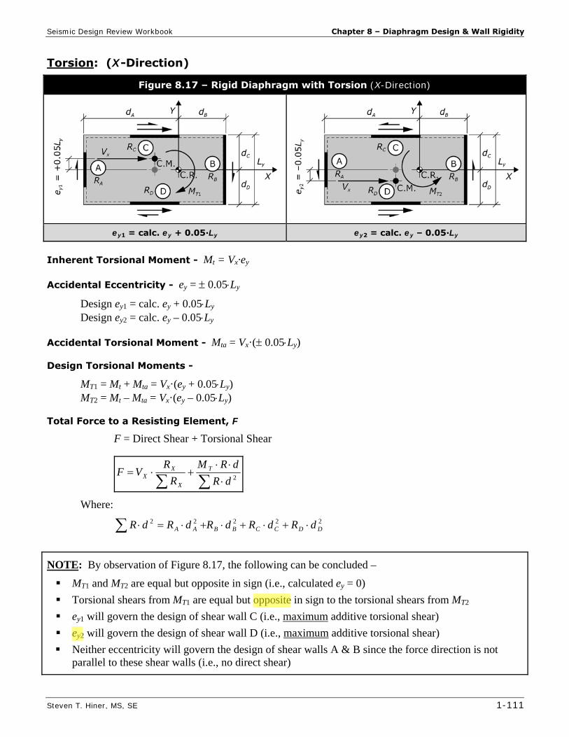
Torsion: (X-Direction)
Figure 8.17 – Rigid Diaphragm with Torsion (X-Direction)
ey1 = calc. ey + 0.05∙Ly ey2 = calc. ey – 0.05∙Ly
Inherent Torsional Moment - Mt = Vx·ey
Accidental Eccentricity - ey = 0.05Ly
Design ey1 = calc. ey + 0.05Ly Design ey2 = calc. ey – 0.05Ly
Accidental Torsional Moment - Mta = Vx·( 0.05Ly)
Design Torsional Moments -
MT1 = Mt + Mta = Vx·(ey + 0.05Ly) MT2 = Mt – Mta = Vx·(ey – 0.05Ly)
Total Force to a Resisting Element, F
F = Direct Shear + Torsional Shear
2
dR
dRM
R
RVF T
X
XX
Where:
22222DDCCBBAA dRdRdRdRdR
NOTE: By observation of Figure 8.17, the following can be concluded –
MT1 and MT2 are equal but opposite in sign (i.e., calculated ey = 0)
Torsional shears from MT1 are equal but opposite in sign to the torsional shears from MT2
ey1 will govern the design of shear wall C (i.e., maximum additive torsional shear)
ey2 will govern the design of shear wall D (i.e., maximum additive torsional shear)
Neither eccentricity will govern the design of shear walls A & B since the force direction is not parallel to these shear walls (i.e., no direct shear)

Seismic Design Review Workbook Chapter 9 – IBC Chapter 23 – Wood
Steven T. Hiner, MS, SE 1-115
Chapter 9 IBC Chapter 23 – Wood
9.1 General IBC §2301
Scope IBC §2301.1 The provisions of IBC Chapter 23 shall govern the materials, design, construction and quality of wood members and their fasteners.
General Design Requirements IBC §2301.2 The design of structural elements or systems constructed partially or wholly of wood or wood-based products, shall be in accordance with one of the following methods:
Allowable Stress Design (ASD) – per IBC §2304, §2305 and §2306
Load and Resistance Factor Design (LRFD) – per IBC §2304, §2305 and §2307
Conventional Light-Frame Construction – per IBC §2304 and §2308
Exception: Buildings designed in accordance with the provisions of the AF&PA Wood Frame Construction Manual (WFCM) shall be deemed to meet the requirements of the provisions of IBC §2308
ICC 400 – for design and construction of log structures
9.2 Lateral-Force-Resisting Systems IBC §2305
General IBC §2305.1 Structures using wood shear walls and wood diaphragms to resist wind, seismic and other lateral loads shall be designed and constructed in accordance with AF&PA Special Design Provisions for Wind and Seismic (SDPWS) and the provisions of IBC §2305 (General), §2306 (ASD), and §2307 (LRFD).
Design Requirements SDPWS §4.1.1 A continuous load path (or paths) with adequate strength and stiffness shall be provided to transfer all forces from their point of application to the final point of resistance.
Boundary Elements SDPWS §4.1.4 Shear wall and diaphragm boundary elements shall be provided to transmit the design tension and
compression forces.
Diaphragm and shear wall sheathing shall not be used to splice boundary elements.
Diaphragm chords and collectors shall be placed in, or in contact with, the plane of the diaphragm framing unless …
Toe-Nailed Connections SDPWS §4.1.7 In SDC = D, E & F – the capacity of toe-nailed connections shall not be used when calculating lateral load resistance to transfer seismic lateral forces > 150 plf for ASD (> 205 plf for LRFD) from diaphragms to shear walls, collectors (or other elements), or from shear walls to other elements.

Chapter 10 – Other Material Chapters Seismic Design Review Workbook
1-144 Steven T. Hiner, MS, SE
9. Controlled low-strength material (CLSM) – IBC §1803.5.9
10. Alternate setback and clearance* – IBC §1803.5.10
11. Seismic Design Category C, D, E & F* – IBC §1803.5.11
An investigation shall be conducted and shall include an evaluation of the following potential hazards resulting from earthquake motions:
Slope instability
Liquefaction
Differential settlement slope instability
Surface displacement due to faulting or lateral spreading
*Exception: The building official shall be permitted to waive the requirement for a geotechnical investigation where satisfactory data from adjacent areas is available that demonstrates an investigation is not necessary for any of the conditions in IBC §1803.5.1 through §1803.5.6, §1803.5.10, and §1803.5.11.
12. Seismic Design Category D, E & F – IBC §1803.5.12
The geotechnical investigation required by IBC §1803.5.11 shall also include:
Determination of lateral pressures on foundation walls and retaining walls due to earthquake motions.
Potential for liquefaction and soil strength loss evaluated for site peak ground accelerations, magnitudes and source characteristics consistent with the design earthquake ground motions …
An assessment of potential consequences of liquefaction and soil strength loss, including estimation of differential settlement, lateral movement, lateral loads on foundations, reduction in foundation soil-bearing capacity, increases in lateral pressures on retaining walls and flotation of buried structures.
Discussion of mitigation measures such as, but not limited to, ground stabilization, selection of appropriate foundation type and depths, selection of appropriate structural systems to accommodate anticipated displacements and forces, or any combination of these measures and how they shall be considered in the design of the structure.
Reporting IBC §1803.6
Where geotechnical investigations are required, a written report of the investigations shall be submitted to the building official by the owner or authorized agent at the time of permit application. See IBC §1803.6 for required information in the report.
Foundations IBC §1808 General IBC – §1808.1
Foundations shall be designed and constructed in accordance with IBC §1808.2 through §1808.9. Shallow foundations shall also satisfy the requirements of IBC §1809. Deep foundations shall also satisfy the requirements IBC §1810.
Design Loads IBC – §1808.3
Foundations shall be designed for the most unfavorable effects due to the combinations of loads specified in IBC §1605.2 (i.e., SD/LRFD) or §1605.3 (i.e., ASD). The dead load is permitted to include the weight

Seismic Design Review Workbook Chapter 14 – Geotechnical Issues & Lifelines
Steven T. Hiner, MS, SE 1-179
Chapter 14 Geotechnical Issues & Lifelines
Geotechnical hazards that can result from earthquake ground motions include:
Liquefaction-induced ground failures,
Earthquake-induced landslides
Surface fault rupture
14.1 Liquefaction Liquefaction is essentially the temporary transformation of a solid material (with grain-to-grain contact) into a fluid like material.
Earthquake ground motions can cause an increase in pore water pressure, which results in a decrease in the soils effective stress. A reduction in effective stress corresponds to a decrease in shear strength. Since the bearing capacity of a soil is a function of the shear strength, the bearing capacity decreases in proportion to the reduction in shear strength. When the shear strength approaches zero, the soil may flow like a fluid.
Earthquake induced soil liquefaction can result in:
Loss of soil bearing capacity Soil settlement Lateral spreading Flow slides on soil slopes
Soils most susceptible to liquefaction are saturated, relatively cohesionless/clay-free sands and silts at or below groundwater, and occasionally loose gravels below the water table deposited by rivers. Other factors include soil density, gradation, confining pressure, and the geologic history of the soil deposit.
Dense sands are less susceptible to liquefaction than loose sands.
Well-graded sands are less susceptible to liquefaction than uniform sands (i.e., more stable interlocking of grains).
Sands below a depth of approximately 50 feet are less susceptible to liquefaction (i.e., due to confining pressure).
Geologically old sand deposits are less susceptible to liquefaction than recent sand deposits (i.e., possibly due to previous earthquake induced settlements & densification).
Extensive damage may occur to structures supported on liquefiable soils due to the loss of bearing capacity and large settlements. Damage might be avoided by supporting the structure on piles or drilled piers that pass through the saturated sand layer that are supported by sound material below (i.e., bedrock). Regardless, liquefaction may still result in settlement of the saturated sand layer below the structure.
Even without the presence of structures on liquefiable soils, lateral spreading alone can cause extensive damage to roadways and pipelines (above or below ground).

Part 2 – Example Problems Seismic Design Review Workbook
2-32 Steven T. Hiner, MS, SE
Solution:
A.) N-S DIRECTION: L = 100′, d = 40′, CASE 3 L/d = 100′/40′ = 2.5:1 < 3:1 max. per SDPWS Table 4.2.4 (see Table 9.1, p. 1-118) for an unblocked
diaphragm → OK
1. Unit Roof Shear on lines A & B, r
VA = VB = wsL / 2 = (300 plf)(100′/2) = 15,000 lbs (SD/LRFD force level)
roof A = B = 0.7·VA / d = 0.7 (15,000 lbs) / 40’ = 262 plfi (ASD force level)
2. Roof Diaphragm Nailing
roof A = 262 plf IBC Table 2306.2.1(1) 15/32” WSP sheathing w/ 8d common (2½″ x 0.131″) @ 6” o.c. edges, unblocked (CASE 3) allowable unit diaphragm shear = 180 plf < 262 plf NG!
Use 15/32″ WSP sheathing w/ 8d common @ 6” o.c. boundary and edge nailing, 12” o.c. field nailing. Blocked (CASE 3) allowable unit diaphragm shear = 270 plf > 262 plf OK
NOTE: Blocking of the roof diaphragm may be terminated when the calculated unit roof shear drops below the allowable unit shear for an unblocked diaphragm (e.g., 180 plf). This occurs approximately 15.6′ from lines A & B.
3. Maximum Chord Force on lines 1 & 2, CF max. M = wsL2 / 8 = (300 plf)(100′)2 / 8 = 375,000 lb-ft (SD/LRFD force level)
max. CF = 0.7·M / d = 0.7 (375,000 lb-ft) / (40′) = 6,560 lbsi (ASD force level)
4. Unit Wall Shear & Nailing on lines A & B, w Wall Line A: total shear wall length, Σb = 20′
h/b = 12′/20′ = 0.60:1 << 2:1 max. per SDPWS Table 4.3.4 (see Table 9.2, p. 1-122) A reduction of unit wall shears in IBC Table 2306.3 is not necessary
wall A = (0.7·VA) / Σb = (1.00)(0.7)(15,000 lbs) / (20′) = 525 plf (ASD force level)
wall A = 525 plf IBC Table 2306.3
Wall Line A - use 15/32″ WSP Structural I sheathing w/ 8d common @ 3″ o.c. edge nailing & 12″ o.c. field nailing … allowable unit wall shear = 550 plf > 525 plf OK (3x studs & blocking required at abutting panel edges & staggered nailing at all panel edges per IBC 2306.3, footnote i )

Seismic Design Review Workbook Part 2 – Example Problems
Steven T. Hiner, MS, SE 2-33
Wall Line B: total shear wall length, Σb = 40′
h/b = 12′/40′ = 0.30:1 << 2:1 max. per SDPWS Table 4.3.4 (see Table 9.2, p. 1-122) A reduction of unit wall shears in IBC Table 2306.3 is not necessary
wall B = (0.7·VB) / Σb = (1.00)(0.7)(15,000 lbs) / (40′) = 262 plf (ASD force level)
wall B = 262 plf IBC Table 2306.3
Wall Line B - use 15/32″ WSP Structural I sheathing w/ 8d common @ 6″ o.c. edge nailing & 12″ o.c. field nailing … allowable unit wall shear = 280 plf > 262 plf OK
5. Drag Force Diagram on lines A & B, Fd
roof A = B = 262 plf (ASD force level)
Wall Line A: Fd = (262 plf)(20′) = 5,240 lbs (ASD force level)
Wall Line B: Fd = 0 lbs
Drag Force – Line A
Drag Force – Line B
B.) E-W DIRECTION: L = 40′, d = 100′, CASE 1 L/d = 40′/100′ = 0.4:1 < 3:1 max. per SDPWS Table 4.2.4 (see Table 9.1, p. 1-118) for an unblocked
diaphragm → OK
1. Unit Roof Shear on lines 1 & 2, r
V1 = V2 = wsL / 2 = (490 plf)(40′/2) = 9,800 lbs (SD/LRFD force level)
roof 1 = 2 = (0.7·V1) / d = (0.7)(9,800 lbs) / 100′ = 69 plfi (ASD force level)
2. Roof Diaphragm Nailing
roof 1 = 69 plf IBC Table 2306.2.1(1) 15/32” WSP sheathing w/ 8d common (2½″ x 0.131″) @ 6″ o.c. edges, unblocked (CASE 1) allowable unit diaphragm shear = 240 plf >> 69 plf OK
BUT … N-S direction required a blocked diaphragm (15.6′ minimum from lines A & B), which governs the diaphragm design! Therefore, provide diaphragm nailing per N-S Direction (part A).

Part 2 – Example Problems Seismic Design Review Workbook
2-34 Steven T. Hiner, MS, SE
3. Maximum Chord Force on lines A & B, CF
max. M = wsL2 / 8 = (490 plf)(40′)2 / 8 = 98,000 lb-ft (SD/LRFD force level)
max. CF = 0.7·M / d = (0.7)(98,000 lb-ft) / (100′) = 690 lbsi (ASD force level)
4. Unit Wall Shear & Nailing on lines 1 & 2, w Wall Line 1: total shear wall length, Σb = 7′ + 13′ = 20′
Maximum h/b = 12′/7′ = 1.71:1 < 2:1 max. per SDPWS Table 4.3.4 (see Table 9.2, p. 1-122) A reduction of unit wall shears in IBC Table 2306.3 is not necessary
wall 1 = (0.7·V1) / Σb = (1.00)(0.7)(9,800 lbs) / (20′) = 343 plf (ASD force level)
wall 1 = 343 plf IBC Table 2306.3
Wall Line 1 - use 15/32″ WSP Structural I sheathing w/ 8d common @ 4″ o.c. edge nailing & 12″ o.c. field nailing for both walls … allowable unit wall shear = 430 plf > 343 plf OK (3x studs & blocking required at abutting panel edges & staggered nailing at all panel edges per IBC 2306.3, footnotes i )
Wall Line 2: total shear wall length, Σb = 10′ + 5′ = 15′
Minimum h/b = 12′/10′ = 1.2:1 < 2:1 maximum per SDPWS Table 4.3.4 (see Table 9.2, p. 1-122) A reduction of unit wall shears in IBC Table 2306.3 is not necessary for 10′ shear wall
Maximum h/b = 12′/5′ = 2.4:1 > 2:1 maximum per SDPWS Table 4.3.4 (see Table 9.2, p. 1-122) A reduction of unit wall shears in IBC Table 2306.3 is necessary for 5′ shear wall … where the reduction factor = 2b/h = 2(5′)/(12′) = 0.83
wall 2 = (0.7·V2) / Σb = (1.00)(0.7)(9,800 lbs) / (15′) = 457 plf (ASD force level)
wall 2 = 457 plf IBC Table 2306.3
15/32″ WSP Structural I sheathing w/ 8d common @ 3″ o.c. edge nailing, 12″ o.c. field nailing.
10′ shear wall - allowable unit wall shear = 550 plf > 457 plf OK (w/ no reduction)
Wall Line 2 – 10′ shear wall - use 15/32″ WSP Structural I sheathing w/ 8d common @ 3″ o.c. edge nailing, 12″ o.c. field nailing … allowable unit wall shear = 550 plf > 457 plf OK (3x studs & blocking required at abutting panel edges & staggered nailing at all panel edges per IBC 2306.3, footnotes i )
15/32″ WSP sheathing w/ 8d common @ 3″ o.c. edge nailing, 12″ o.c. field nailing.
5′ shear wall - allowable unit wall shear = (0.83)(550 plf) = 456 plf ≈ 457 plf OK
Wall Line 2 – 5′ shear wall - use 15/32″ WSP Structural I sheathing w/ 8d common @ 3″ o.c. edge nailing, 12″ o.c. field nailing … allowable unit wall shear = 0.83(550 plf) = 456 plf ≈ 457 plf OK (3x studs & blocking required at abutting panel edges & staggered nailing at all panel edges per IBC 2306.3, footnotes i )
NOTE: – the allowable unit wall shear reduction factor 2b/h per SDPWS Table 4.3.4, footnote 1 can easily result in separate wood structural panel shear walls on the same wall line with different required edge nail spacing … as nearly occurred in this example on Wall Line 2.

Part 2 – Example Problems Seismic Design Review Workbook
2-46 Steven T. Hiner, MS, SE
Problem #19 Given: Single-story building w/ special
steel concentrically braced frames
Concrete (rigid) roof diaphragm
Relative stiffness of frames shown on plan
Calculated Center of Mass (CM) and Center of Rigidity/Stiffness (CR) shown per Plan
Seismic base shear, N-S & E-W Directions, V = 300 kips
Plan
Find:
A.) N-S DIRECTION:
1. Accidental eccentricity (ex), accidental & inherent torsional moments (Mta & Mt)
2. Design eccentricities (ex1 & ex2) and design torsional moments (MT1 & MT2)
3. Building plan sketch showing direct & torsional shears for each design eccentricity
4. Total design force to frames A, B & C
B.) E-W DIRECTION:
1. Accidental eccentricity (ey), accidental & inherent torsional moments (Mta & Mt)
2. Design eccentricities (ey1 & ey2) and design torsional moments (MT1 & MT2)
3. Building plan sketch showing direct & torsional shears for each design eccentricity
4. Total design force to frames 1 & 2

Part 2 – Example Problems Seismic Design Review Workbook
2-52 Steven T. Hiner, MS, SE
B.) Center of Rigidity, CR
Shear Wall Rigidities: (assume cantilever walls, Table D1 - Relative Rigidity of Cantilever Shear Walls / Piers, Appendix D, p. 5-18)
Wall A : H/D = 15′/30′ = 0.50 Table D1 (p. 5-18) RA = 5.0
Wall B : H/D = 15′/20′ = 0.75 Table D1 (p. 5-18) RB = 2.54
BAY RRR = 5.0 + 2.54 = 7.54
Wall C : H/D = 15′/40′ = 0.375 Table D1 (p. 5-18) RC = 7.49
Wall D : RD = RB = 2.54
Wall E : RE = RD = 2.54
EDCX RRRR = 7.49 + 2.54 + 2.54 = 12.57
Y
YCR
R
xRX = [5.0 (0′) + 2.54 (80′)] / (7.54) = 26.9 feeti
X
XCR
R
yRY = [7.49 (40′) + 2.54 (10′) + 2.54 (0′)] / (12.57) = 25.9 feeti
Part 2 – Example Problems Seismic Design Review Workbook
2-54 Steven T. Hiner, MS, SE
Maximum FB =
2
1
dR
dRM
R
RV BBT
Y
BY
= [73.4 kips (2.54) / (7.54)] + [888.1 kip-ft (2.54) (53.1 ft) / (14,615 ft2)]
= 24.7 kips + 8.2 kips = 32.9 kipsi
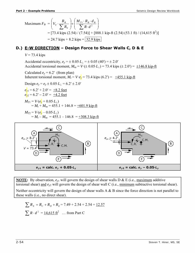
D.) E-W DIRECTION – Design Force to Shear Walls C, D & E
V = 73.4 kips
Accidental eccentricity, ey = 0.05L = 0.05 (40′) = 2.0′ Accidental torsional moment, Mta = V·( 0.05L) = 73.4 kips ( 2.0′) = 146.8 kip-ft
Calculated ey = 6.2′ (from plan) Inherent torsional moment, Mt = V·ey = 73.4 kips (6.2′) = +455.1 kip-ft
Design ey = ey 0.05L = 6.2′ 2.0′
ey1 = 6.2′ + 2.0′ = +8.2 feet ey2 = 6.2′ 2.0′ = +4.2 feet
MT1 = V(ey + 0.05L) = Mt + Mta = 455.1 + 146.8 = +601.9 kip-ft
MT2 = V(ey – 0.05L) = Mt – Mta = 455.1 – 146.8 = +308.3 kip-ft
ey1 = calc. ey + 0.05∙Ly ey2 = calc. ey – 0.05∙Ly
NOTE: By observation, ey1 will govern the design of shear walls D & E (i.e., maximum additive torsional shear) and ey2 will govern the design of shear wall C (i.e., minimum subtractive torsional shear).
Neither eccentricity will govern the design of shear walls A & B since the force direction is not parallel to these walls (i.e., no direct shear).
EDCX RRRR = 7.49 + 2.54 + 2.54 = 12.57
2dR = 14,615 ft2 … from Part C
Seismic Design Review Workbook Part 2 – Example Problems
Steven T. Hiner, MS, SE 2-57
Solution:
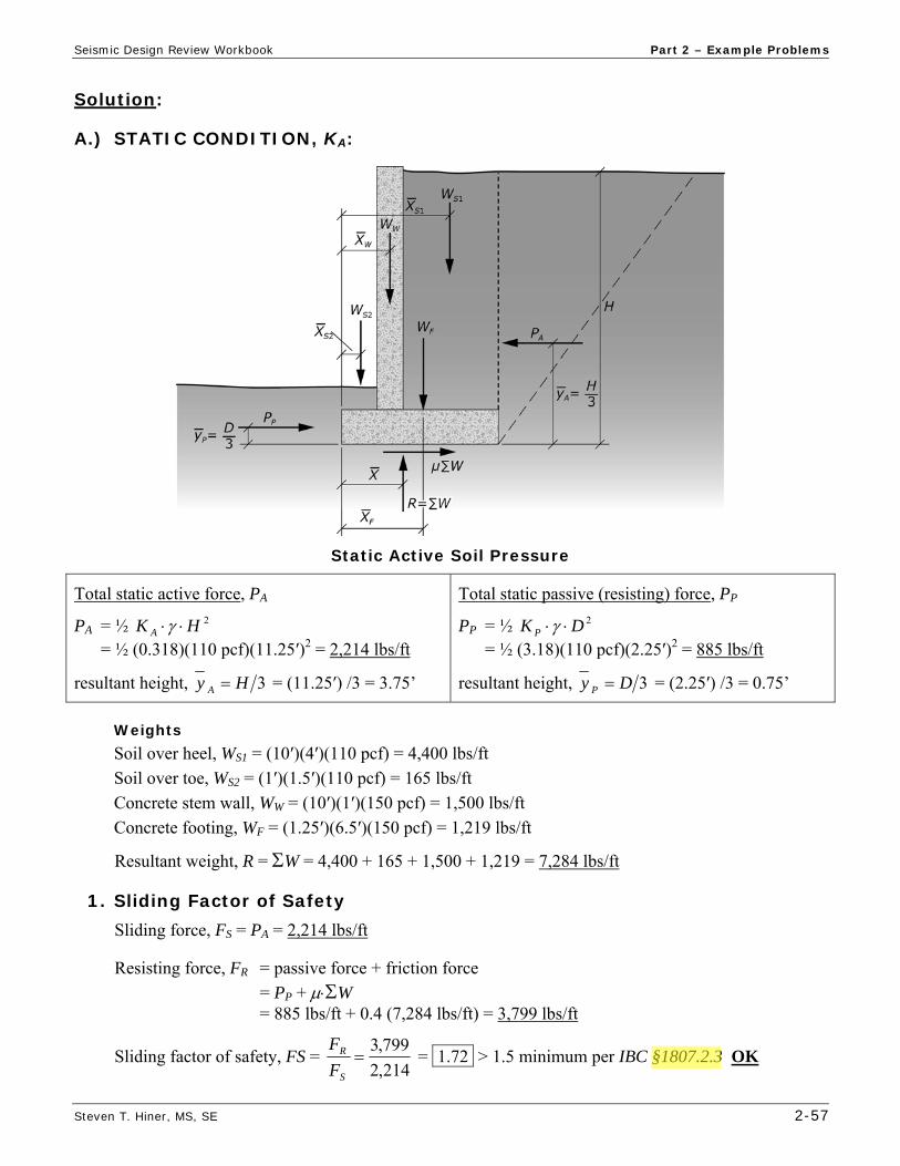
A.) STATIC CONDITION, KA:
Static Active Soil Pressure
Total static active force, PA
PA = ½ 2HK A = ½ (0.318)(110 pcf)(11.25′)2 = 2,214 lbs/ft
resultant height, 3Hy A = (11.25′) /3 = 3.75’
Total static passive (resisting) force, PP
PP = ½ 2DK P = ½ (3.18)(110 pcf)(2.25′)2 = 885 lbs/ft
resultant height, 3Dy P = (2.25′) /3 = 0.75’
Weights Soil over heel, WS1 = (10′)(4′)(110 pcf) = 4,400 lbs/ft
Soil over toe, WS2 = (1′)(1.5′)(110 pcf) = 165 lbs/ft
Concrete stem wall, WW = (10′)(1′)(150 pcf) = 1,500 lbs/ft
Concrete footing, WF = (1.25′)(6.5′)(150 pcf) = 1,219 lbs/ft
Resultant weight, R = W = 4,400 + 165 + 1,500 + 1,219 = 7,284 lbs/ft
1. Sliding Factor of Safety Sliding force, FS = PA = 2,214 lbs/ft
Resisting force, FR = passive force + friction force
= PP + W = 885 lbs/ft + 0.4 (7,284 lbs/ft) = 3,799 lbs/ft
Sliding factor of safety, FS = 214,2
799,3
S
R
F
F = 1.72 > 1.5 minimum per IBC §1807.2.3 OK

Part 2 – Example Problems Seismic Design Review Workbook
2-58 Steven T. Hiner, MS, SE
2. Overturning Factor of Safety
Overturning moment, OTM = AA yP
= (2,214 lbs/ft)(11.25′/3) = 8,302 lbft/ft
Resisting moment,
RM = FFWWSSSSPP xWxWxWxWyP 2211
= 885 lbs/ft (2.25′)/3 + 4,400 (4.5′) + 165 (0.75′) + 1,500 (2′) + 1,219 (3.25′) = 27,550 lbft/ft
Overturning factor of safety, FS = 302,8
550,27
OTM
RM = 3.32 > 1.5 minimum per IBC §1807.2.3 OK
3. Maximum Soil Bearing Pressure
284,7
302,8550,27
R
OTMRMx = 2.64′
eccentricity from centerline of footing,
xLe 2 = (6.5′)/2 – 2.64′ = 0.61′
Soil Bearing Pressure
if e < L/6 (i.e., R is within middle 1/3 of footing) the soil pressure distribution is trapezoidal
if e L/6 (i.e., R is outside of middle 1/3 of footing) the soil pressure distribution is triangular
e = 0.61′ < L/6 = 6.5′/6 = 1.08′ soil pressure distribution is trapezoidal
for a trapezoidal soil pressure distribution,
maximum soil pressure, qs =
L
e
L
R 61
minimum soil pressure, qs =
L
e
L
R 61
therefore, max. qs =
'5.6
)'61.0(61
'5.6
284,7= 1,750 psf/fti < 3,000 psf allowable (D + L) OK

Seismic Design Review Workbook Part 2 – Example Problems
Steven T. Hiner, MS, SE 2-59
B.) STATIC PLUS SEISMIC CONDITION, KAE:
Static plus Seismic Active Soil Pressure
Total static plus seismic active force, PAE
PAE = ½ 2HK AE = ½ (0.538)(110 pcf)(11.25′)2 = 3,745 lbs/ft
resultant height, AEy = 0.45H
= 0.45 (11.25′) = 5.06′
Total static passive (resisting) force, PP (from part A)
PP = 885 lbs/ft
resultant height, 3Dy P = 0.75′
Weights (from part A)
Resultant weight, R = W = 7,284 lbs/ft
1. Sliding Factor of Safety Sliding force, FS = PAE = 3,745 lbs/ft
Resisting force, FR = passive force + friction force
= PP + W = 885 lbs/ft + 0.4 (7,284 lbs/ft) = 3,799 lbs/ft
Sliding factor of safety, FS = 745,3
799,3
S
R
F
F = 1.01 < 1.5 / 1.33 = 1.1 NG!
NOTE: 2009 IBC §1605.3.2 & §1806.1 (and most Geotechnical reports) allow a one-third increase in allowable stress for all load combinations that include short-term loads such as earthquake (or wind). Although not specifically addressed in the IBC, many designers allow a reduced factor for safety (for sliding and overturning) when considering these short-term loads … i.e., short term FS = 1.5 / 1.33 = 1.1

Part 3 – Multiple Choice Problems Seismic Design Review Workbook
3-14 Steven T. Hiner, MS, SE
3.43 Which of the following occupancies types would never be assigned to Seismic Design Category F (SDC = F)?
a. Hospital b. Single-family residence c. County jail d. Both b & c
3.44 A 5-story building with offices in the upper four stories and a fire station in the first story,
would be assigned to what Occupancy Category per IBC Table 1604.5?
a. I b. II c. III d. IV
3.45 What would be the most appropriate spectral acceleration response parameters (SS & S1) for a
building project proposed at 36º00′00″ Latitude and -120º00′00″ Longitude?
a. SS = 1.75 & S1 = 0.80 b. SS = 1.75 & S1 = 0.60 c. SS = 0.95 & S1 = 0.35 d. SS = 0.75 & S1 = 0.35
3.46 What would be the most appropriate spectral acceleration response parameters (SS & S1) for a
building project proposed at 39º00′00″ Latitude and -123º00′00″ Longitude?
a. SS = 2.00 & S1 = 0.70 b. SS = 1.55 & S1 = 0.70 c. SS = 1.25 & S1 = 0.55 d. SS = 1.25 & S1 = 0.45
3.47 MCE mapped spectral response acceleration parameters SS & S1 are determined based on which
site class?
a. Site Class A b. Site Class B c. Site Class C d. Site Class D
3.48 Given SS = 0.63 & S1 = 0.25, with no soils report, what site coefficients Fa & Fv would be most
appropriate per the IBC?
a. Fa = 1.0 & Fv = 1.0 b. Fa = 1.2 & Fv = 1.8 c. Fa = 1.3 & Fv = 1.9 d. Fa = 1.4 & Fv = 2.0

Seismic Design Review Workbook Part 3 – Multiple Choice Problems
Steven T. Hiner, MS, SE 3-27
4.68 A structural analysis has been performed on a two-story apartment building (with parking garage in the first-story). The lateral story strength of the first and second stories were determined to be 57 kips and 76 kips respectively. The story stiffness of the first and second stories was determined to be 14 kips/inch and 19.5 kips/inch respectively. Which of the following vertical irregularities are present in this structure?
I. Stiffness – Soft Story II. Discontinuity in Lateral Strength – Weak Story
a. I b. II c. I & II d. None of the above
4.69 Which of the following structures are considered to have a Weight (Mass) Irregularity?
I. II. III.
a. I b. I & II c. II & III d. I, II & III
4.70 Which of the following braced frame structures is likely to have a Stiffness-Soft Story
Irregularity?
I. II. III.
a. I b. I & II c. I & III d. I, II & III

Part 3 – Multiple Choice Problems Seismic Design Review Workbook
3-30 Steven T. Hiner, MS, SE
Using the figures below, answer questions 4.79 through 4.82
a. b. c. d.
4.79 Which figure best represents the Equivalent Lateral Force (ELF) procedure vertical distribution of seismic forces (Fx) for structures with a period (T ) less than or equal to 0.5 seconds?
4.80 Which figure best represents the Equivalent Lateral Force (ELF) procedure story shear distribution (Vx) for structures with a period (T ) less than or equal to 0.5 seconds?
4.81 Which figure best represents the Simplified Design procedure vertical distribution of seismic forces (Fx)?
4.82 Which figure best represents the Equivalent Lateral Force (ELF) procedure vertical distribution of seismic forces (Fx) for structures with a period (T ) greater than or equal to 2.5 seconds?
4.83 Given a 15-story Office Bldg w/ steel moment frames, which site class is likely to result in the largest seismic forces?
a. Site Class B (rock) b. Site Class C (dense soil) c. Site Class D (stiff soil) d. Site Class E (soft soil)
4.84 Given two structures with the same R, I, SDS = 0.73 & SD1 = 0.30. Structure A has a period (TA)
of 0.35 second. Structure B has an effective seismic weight of 3 times that of Structure A (i.e., WB = 3·WA). What would be the period of Structure B such that the Base Shear (V) of the two structures would be equal?
a. 0.35 second b. 0.65 second c. 1.25 seconds d. 2.15 seconds

Part 3 – Multiple Choice Problems Seismic Design Review Workbook
3-52 Steven T. Hiner, MS, SE
8.43 Assuming flexible diaphragms at all levels, what should be the force used to design the shear walls in the 2nd story?
a. Vertical distribution force at level 2, F2 b. Diaphragm design force at level 2, Fp2 c. 2nd story shear, V2 d. Base shear, V
8.44 Assuming flexible diaphragms at all levels, what should be the force used to design the chords
and collectors at level 2?
a. Vertical distribution force at level 2, F2 b. Diaphragm design force at level 2, Fp2 c. 2nd story shear, V2 d. Base shear, V
Given the single story building below with a flexible roof diaphragm and a base shear, V = 15 kips, answer questions 8.45 through 8.59
Plan
8.45 What is the lateral force in the shear wall on line 1?
a. 6.0 kips b. 7.5 kips c. 9.0 kips d. 12.0 kips
8.46 What is the lateral force in the shear wall on line 2?
a. 6.0 kips b. 7.5 kips c. 9.0 kips d. 12.0 kips

Seismic Design Review Workbook Part 3 – Multiple Choice Problems
Steven T. Hiner, MS, SE 3-55
Given the three story office building below with a base shear of 24 kips, approximate fundamental period of 0.25 second, SDS = 0.60 & SD1 = 0.25, answer questions 8.60 through 8.62
Elevation 8.60 What is the lateral force at the 2nd floor level using ASCE 7-05 §12.8.3?
a. 5.3 kips b. 8.6 kips c. 10.2 kips d. 18.7 kips
8.61 What is the 2nd story shear?
a. 10.2 kips b. 18.7 kips c. 24.0 kips d. None of the above
8.62 What is the diaphragm design force at the 3rd floor level (assume all wpx = wx)?
a. 5.3 kips b. 8.6 kips c. 10.3 kips d. 18.7 kips
9.1 For wood structural panel horizontal diaphragms, what is the minimum sheet dimension at boundaries with blocking omitted?
a. 12" b. 18" c. 24" d. 48"
9.2 What is the maximum length-width (i.e., span-depth) ratio for an unblocked wood structural
panel horizontal diaphragm?
a. 2:1 b. 3:1 c. 3½:1 d. 4:1

Seismic Design Review Workbook Part 3 – Multiple Choice Problems
Steven T. Hiner, MS, SE 3-57
9.7 What is the maximum unit roof shear at Allowable Stress Design (ASD) force level?
a. 240 plf b. 400 plf c. 480 plf d. 800 plf
9.8 What is the maximum drag force at Allowable Stress Design (ASD) force level?
a. 2.4 kips b. 4.8 kips c. 6.0 kips d. 9.6 kips
9.9 What is the hold-down force at Allowable Stress Design (ASD) force level assuming a 10 foot
wall height, 30 foot shear wall width, = 1.0, and neglecting the wall (and tributary roof) weight?
a. 2.0 kips b. 4.0 kips c. 8.0 kips d. 12.0 kips
9.10 Given a seismic base shear V = CS W = 0.196W at Strength Design (SD) force level. For the
single story flexible roof diaphragm plan below, find the unit diaphragm shear at Allowable Stress Design (ASD) force level, for East-West loads. Roof DL = 25 psf, wall DL = 15 psf & 12 foot wall heights.
a. 50 plf b. 80 plf c. 155 plf d. 170 plf
Plan
9.11 The contractor of a one-story wood frame commercial building project is proposing to substitute 15/32″ Structural I wood structural panel sheathing for the shear walls. The approved plans call for 3/8″ rated wood structural panel sheathing with 8d common (2½″ x 0.131″) at 2″ o.c. edge nailing. As the project engineer, which of the following nail size and edge nail spacing would provide the lowest acceptable allowable unit shear value?
a. 10d common at 6″ o.c. b. 10d common at 4″ o.c. c. 10d common at 3″ o.c. d. 10d common at 2″ o.c.

Part 3 – Multiple Choice Problems Seismic Design Review Workbook
3-60 Steven T. Hiner, MS, SE
9.21 What is the purpose of the subdiaphragms in a building with reinforced masonry (or concrete) shear walls?
a. Transfer out-of-plane wall anchorage forces into the roof diaphragm b. Transfer in-plane diaphragm unit shears into the shear walls c. Transfer in-plane diaphragm unit shears into the collector d. All of the above
9.22 What is the maximum length-width (i.e., span-depth) ratio for a blocked wood structural panel
horizontal diaphragm?
a. 2:1 b. 3:1 c. 3.5:1 d. 4:1
9.23 What is the maximum length-to-width (i.e., span-depth) ratio for a wood structural panel
subdiaphragm?
a. 2:1 b. 2.5:1 c. 3:1 d. 4:1
9.24 What is the maximum height-width ratio of a blocked wood structural panel shear wall where
the unit shear values of IBC Table 2306.3 may be used without any adjustment (i.e., need not be reduced) when resisting seismic forces?
a. 3.5:1 b. 3:1 c. 2.5:1 d. 2:1
9.25 Given a wood structural panel shear wall with a height-width ratio of 3:1, what reduction factor
would need to be applied to the unit shear values of IBC Table 2306.3 when resisting seismic forces?
a. 0.82 b. 0.75 c. 0.67 d. 0.33
Given a two-story Bearing Wall System building with special reinforced masonry shear walls, assigned to Seismic Design Category D (SDC = D), and with blocked wood structural panel (flexible) diaphragms at the second floor and roof levels. Answer questions 9.26 through 9.27 below.
9.26 What Response Modification Coefficient (R) is appropriate for determining the seismic base shear?
a. 2 b. 3½ c. 5 d. 5½

Seismic Design Review Workbook Part 3 – Multiple Choice Problems
Steven T. Hiner, MS, SE 3-73
14.5 A City’s municipal water supply pipe is proposed to cross an active strike-slip fault. Which of the following combinations is least likely to result in damage to this lifeline when subjected to a localized fault rupture?
a. Pipe above ground oriented at 45 degrees to the fault b. Pipe below ground oriented at 45 degrees to the fault c. Pipe above ground oriented at 90 degrees to the fault d. Pipe below ground oriented at 90 degrees to the fault
14.6 In order for liquefaction to occur during an earthquake, which of the following conditions are
required to be present?
a. High groundwater table b. Granular soils (e.g., sand, silty sand, sandy silt, etc.) c. Low density in the granular soils d. All of the above
15.1 Which of the following projects can a California licensed Civil Engineer design and be in
responsible charge?
I. Concrete culvert under a freeway II. Public school building III. Vehicle bridge
a. II b. I & II c. I & III d. I, II & III
15.2 A California licensed Civil Engineer has experience in bridge design only. Which of the
following is she/he able to design?
I. A hospital under the supervision of a licensed Civil Engineer with hospital design experience
II. A building under the supervision of a licensed Structural Engineer III. A vehicle bridge between two buildings
a. I & II b. I & III c. II & III d. I, II & III
15.3 Given a two-story wood frame single family dwelling entirely of “conventional
construction”, who is allowed to prepare the plans (and specifications)?
I. Architect II. Civil Engineer III. Non-registered person
a. I b. II c. I & II d. I, II & III

Seismic Design Review Workbook Part 4 – Multiple Choice Solutions
Steven T. Hiner, MS, SE 4-1
Problem Answer Reference / Solution
1.1 d Earthquake design applies to all structures such as buildings, highway bridges, railroad bridges, dams, etc. The International Building Code & ASCE 7-05 apply to buildings, “nonbuilding” structures, etc. All structures
1.2 b p. 1-1, Figure 1.1 The epicenter is the point on the Earth's surface directly above the hypocenter. epicenter
1.3 b p. 1-1, Figure 1.1 The place in the Earth's crust where this energy release occurs is known as the hypocenter (or focus). hypocenter
1.4 b p. 1-1, Nature of earthquakes Often times, a major earthquake is preceded by smaller earthquakes known as foreshocks … foreshocks
1.5 a p. 1-2, Fault types Fault movement may occur suddenly, or as slow continuous (or intermittent) movement without noticeable earthquakes known as fault creep. fault creep
1.6 d p. 1-2, Fault types The San Andreas fault is a right-lateral fault more than 600 miles long. right-lateral
1.7 c p. 1-2, Seismic sea waves Seismic sea waves (or Tsunami’s) occur when a vertical fault movement occurs on the ocean floor (i.e., normal fault or reverse fault). I & II
1.8 d p. 1-3, Seismic waves & Figure 1.3 Shear waves (S-waves) are most effective in damaging structures near the epicenter … and therefore, most responsible for the strong ground motion portion of an earthquake. Shear waves
1.9 b Ground accelerations are the cause of seismic forces in a structure. ground acceleration
1.10 c p. 1-5, Earthquake intensity Modified Mercalli (Intensity) scale

Seismic Design Review Workbook Part 4 – Multiple Choice Solutions
Steven T. Hiner, MS, SE 4-9
Problem Answer Reference / Solution
3.40 c 1-29 & 2009 IBC p. 343, §1613.5.6 & Tables 1613.5.6(1) & 1613.5.6(2) Occupancy Category II – IBC Table 1604.5 (p. 307) for apartment building S1 = 0.20 < 0.75 use Tables 1613.5.6(1) & (2) to determine SDC SDS = 0.41 & OC = II Table 1613.5.6(1) SDC = C SD1 = 0.20 & OC = II Table 1613.5.6(2) SDC = D governs use Seismic Design Category D, SDC = D
3.41 d 1-26 & ASCE 7-05 p. 128, Tables 12.2-1 & 12.6-1 SDC determines the permissible lateral analysis procedure, building height limit, and seismic detailing requirements of the SFRS all of the above
3.42 c 1-26, Table 3.1 Seismic Design Category C = Moderate seismic hazard level
3.43 d p. 1-29 & 2009 IBC p. 343, §1613.5.6 a. Hospital (Group I-2) IBC Table 1604.5 OC = IV b. Single-family residence (Group R-3) IBC Table 1604.5 OC = II c. County jail (Group I-3) IBC Table 1604.5 OC = III Seismic Design Category F applies only to Occupancy Category IV structures (i.e., essential facilities, etc.). SDC = F does not apply to Occupancy Category I, II or III structures … Both b & c
3.44 d p. 1-20 & 2009 IBC p. 306 & 307, §1604.5.1 & Table 1604.5 Where a building or structure is occupied by two or more occupancies not included in the same Occupancy Category, it shall be assigned the classification of the highest Occupancy Category corresponding to the various occupancies. Office building IBC Table 1604.5 OC = II Fire station IBC Table 1604.5 OC = IV (governs) use Occupancy Category IV
3.45 b 2009 IBC p. 353 & 355, Figures 1613.5(3) & 1613.5(4) At 36º00′00″ Latitude and -120º00′00″ Longitude … Figure 1613.5(3) SS ≈ 1.75 Figure 1613.5(4) S1 ≈ 0.60
3.46 b 2009 IBC p. 352 & 354, Figures 1613.5(3) & 1613.5(4) At 39º00′00″ Latitude and -123º00′00″ Longitude … Figure 1613.5(3) SS ≈ 1.55 Figure 1613.5(4) S1 ≈ 0.70
3.47 b 2009 IBC p. 348 to 365, Figures 1613.5(1) to 1613.5(14) Site Class B

Part 4 – Multiple Choice Solutions Seismic Design Review Workbook
4-14 Steven T. Hiner, MS, SE
Problem Answer Reference / Solution Or using Table C1 (p. 5-16) Dual Systems & hn = 35′ Ta = 0.29 sec Ta = 0.29 second
4.23 a p. 1-43 & ASCE 7-05 p. 128, Table 12.6-1 3.5·TS = 3.5·(0.6) = 2.10 seconds SDC = D & T = 2.4 seconds > 3.5·TS Table 12.6-1 ELF procedure is NP (not permitted). All others allow use of the ELF procedure. A regular structure with T = 2.4 seconds
4.24 c ASCE 7-05 p. 120, Table 12.2-1, item B.3 Steel SCBF’s, R = 6
4.25 c ASCE 7-05 p. 120, Table 12.2-1, item B.3 Ω0 = 2
4.26 b ASCE 7-05 p. 120, Table 12.2-1, item B.3 H = 160 feet
4.27 d p. 1-49 & ASCE 7-05 p. 129, §12.8.2.1 Ta = Ct (hn)
x ASCE 7 (12.8-7) Ct = 0.02 & x = 0.75 ASCE 7 p. 129, Table 12.8-2 (all others) Steel SCBF Ta = 0.02 (140′)0.75 = 0.81 sec Or using Table C1 (p. 5-16) CBF & hn = 140′ Ta = 0.81 sec Ta = 0.8 second
4.28 e p. 1-37 & ASCE 7-05 p. 120 & 121, Table 12.2-1 R is proportional to ductility (i.e., larger R = more ductile) Steel SCBF Table 12.2-1, item B.3 - R = 6 Light-framed WSP shear walls Table 12.2-1, item A.13/B.23 - R = 6½ / 7 Reinforced concrete SMF Table 12.2-1, item C.5 - R = 8 Steel EBF w/ steel SMF (Dual System) Table 12.2-1, item D.1 - R = 8 Both c & d
4.29 d p. 1-37, ductility is not related to flexibility or stiffness. None of the above
4.30 a p. 1-37, Figure 4.4 K = V / Δ Largest K = “steepest” elastic curve (i.e., straightline portion) Shear Wall A is the most stiff
4.31 d p. 1-37, Figure 4.4 K = V / Δ Lowest K = “flattest” elastic curve (i.e., straightline portion) Shear Wall D is the least stiff
4.32 b p. 1-37, Figure 4.4 Shear Wall B would be the most ductile

Part 4 – Multiple Choice Solutions Seismic Design Review Workbook
4-24 Steven T. Hiner, MS, SE
Problem Answer Reference / Solution
4.86 d p. 1-57, Building Separation & IBC p. 345, §1613.6.7 From Problem 4.85 - Structure 1: At Level 7 (roof) - δM1 = Cd·δmax / I = (5½)(3.5″) / (1.00) = 19.25″
Where a structure adjoins a property line (not common to a public way), the structure shall be set back from the property line by not less than M
Structure 1 setback from property line, δM1 = 19.25″
19 inches
4.87 b p. 1-57, Building Separation & IBC p. 345, §1613.6.7 From Problem 4.85 - Structure 2: At Level 4 (roof) - δM2 = Cd·δmax / I = (4)(1.4″) / (1.00) = 5.60″
Where a structure adjoins a property line (not common to a public way), the structure shall be set back from the property line by not less than M
Structure 2 setback from property line, δM2 = 5.60″
6 inches
4.88 a p. 1-10, Natural Period
/2 gKWT
Increase in stiffness (K) will result in a decrease in structure period (T ). While a decrease in period can result in an increase in base shear (V ) and lateral forces at each level (Fx), the increase in overall stiffness should more than compensate the increased force level and result in a decrease in story drifts.
Decrease in period and decrease in story drifts
4.89 a p. 1-36 & 37, Response Modification Coefficient - R The R coefficient is representative of the inherent overstrength and global ductility of a seismic-force-resisting system (SFRS).
The higher R structure has greater ductility
4.90 b p. 1-47 & ASCE 7-05 p. 129, §12.8.1.1 Office Building = Occupancy Category II – IBC p. 307, Table 1604.5 I = 1.0 – ASCE 7-05 p. 116, Table 11.5-1 R = 5 – ASCE 7-05 p. 120, Table 12.2-1, item A.7 Ts = SD1/SDS = (0.30) / (0.75) = 0.40 second Ta = 0.21 second < Ts ASCE 7 (12.8-2) governs for Cs
0.15
75.0
IR
SC DS
S = 0.15 ASCE 7 (12.8-2)
V = Cs·W ASCE 7 (12.8-1) = 0.150·W
Part 4 – Multiple Choice Solutions Seismic Design Review Workbook
4-40 Steven T. Hiner, MS, SE
Problem Answer Reference / Solution
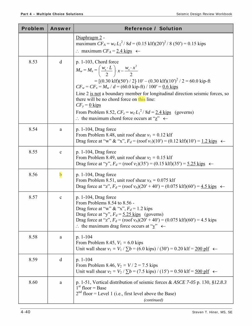
Diaphragm 2 - maximum CFA = wsL2
2 / 8d = (0.15 klf)(20′)2 / 8 (50′) = 0.15 kips
maximum CFA = 2.4 kips
8.53 d p. 1-103, Chord force
Mw = Mx =
= [(0.30 klf)(50′) / 2]10′ – (0.30 klf)(10′)2 / 2 = 60.0 kip-ft CFw = CFx = Mw / d = (60.0 kip-ft) / 100′ = 0.6 kips
Line 2 is not a boundary member for longitudinal direction seismic forces, so there will be no chord force on this line: CFy = 0 kips
From Problem 8.52, CFz = wsL12 / 8d = 2.4 kips (governs)
the maximum chord force occurs at “z”
8.54 a p. 1-104, Drag force From Problem 8.48, unit roof shear v1 = 0.12 klf Drag force at “w” & “x”, Fd = (roof v1)(10′) = (0.12 klf)(10′) = 1.2 kips
8.55 c p. 1-104, Drag force From Problem 8.49, unit roof shear v2 = 0.15 klf Drag force at “y”, Fd = (roof v2)(35′) = (0.15 klf)(35′) = 5.25 kips
8.56 b
p. 1-104, Drag force From Problem 8.51, unit roof shear vA = 0.075 klf Drag force at “z”, Fd = (roof vA)(20′ + 40′) = (0.075 klf)(60′) = 4.5 kips
8.57 c p. 1-104, Drag force From Problems 8.54 to 8.56 - Drag force at “w” & “x”, Fd = 1.2 kips Drag force at “y”, Fd = 5.25 kips (governs) Drag force at “z”, Fd = (roof vA)(20′ + 40′) = (0.075 klf)(60′) = 4.5 kips the maximum drag force occurs at “y”
8.58 a p. 1-104 From Problem 8.45, V1 = 6.0 kips Unit wall shear v1 = V1 / ∑b = (6.0 kips) / (30′) = 0.20 klf = 200 plf
8.59 d p. 1-104 From Problem 8.46, V2 = V / 2 = 7.5 kips Unit wall shear v2 = V2 / ∑b = (7.5 kips) / (15′) = 0.50 klf = 500 plf
8.60 a p. 1-51, Vertical distribution of seismic forces & ASCE 7-05 p. 130, §12.8.3 1st floor = Base 2nd floor = Level 1 (i.e., first level above the Base)
(continued)
22
2s xw
xLw s

Seismic Design Review Workbook Part 4 – Multiple Choice Solutions
Steven T. Hiner, MS, SE 4-43
Problem Answer Reference / Solution
9.6 b p. 1-122, Table 9.2 & SDPWS Table 4.3.4 h/b 3.5 maximum (requires reduction factor 2b/h for seismic) minimum b = (h/3.5) = 10′ / 3.5 = 2.86′ 2′-10″
9.7 a p. 1-121, Wood structural panel diaphragms Vmax = w·L / 2 = V / 2 = 33.6 kips / 2 = 16.8 kips for ASD, roof = (0.7·Vmax) / d = 0.7(16.8 kips) / 50′ = 235 plf 240 plf
9.8 b p. 1-104, Drag force Maximum drag force occurs on right (i.e., East) wall line at 20′ from South end of collector (i.e., South end of 30′ shear wall) – for ASD, max Fd = roof (20′) = (240 plf)(20′) = 4,800 lbs = 4.8 kips
9.9 b p. 1-130, Shear wall overturning / Hold-downs = 1.0 (given) V1 = V2 = V / 2 = 33.6 kips / 2 = 16.8 kips
'30
)'10)(8.16)(0.1(7.0)(7.0 1
b
hVT
= – 3.92 kips
for ASD, uplift T = 4.0 kips
9.10 b p. 1-121, Wood structural panel diaphragms V = CS W = 0.196W (given) For a single-story building – ws = fp1 = Fp1 / L = CS ·wp1 East-West: ws = 0.196 [(25 psf)(75′) + (15 psf)(12′/2)·4 walls] = 438 plf Vmax = wsL / 2 = (438 plf)(40′) / 2 = 8,760 lbs for ASD, roof = (0.7·Vmax) / d = 0.7·(8,760 lbs) / 75′ = 82 plf 80 plf
9.11 c 2009 IBC p. 474, Table 2306.3 3/8″ rated sheathing w/ 8d common (2½″ x 0.131″) @ 2″ o.c. = 530 plf 15/32″ Structural I w/ 10d common @ 6″ o.c. = 340 plf < 530 plf NG! 15/32″ Structural I w/ 10d common @ 4″ o.c. = 510 plf < 530 plf NG! 15/32″ Structural I w/ 10d common @ 3″ o.c. = 665 plf > 530 plf OK 15/32″ Structural I w/ 10d common @ 2″ o.c. = 870 plf >> 530 plf OK
use 15/32″ Structural I w/ 10d common @ 3″ o.c. = 665 plf 530 plf
9.12 d 2009 IBC p. 470, Table 2306.2.1(1) Load parallel to continuous panel joints = Case 3 (weak direction) 15/32″ sheathing w/ 8d @ 6″ o.c. unblocked = 180 plf < 275 plf NG! 15/32″ sheathing w/ 10d @ 6″ o.c. unblocked = 190 plf < 275 plf NG! 15/32″ sheathing w/ 8d @ 6″ o.c. blocked = 270 plf < 275 plf NG! 15/32″ sheathing w/ 10d @ 6″ o.c. blocked = 290 plf 275 plf OK
use 15/32″ sheathing w/ 10d common @ 6″ o.c. = 290 plf 275 plf
9.13 d p. 1-100, Flexible diaphragm analysis V = CS W
(continued)

Part 4 – Multiple Choice Solutions Seismic Design Review Workbook
4-46 Steven T. Hiner, MS, SE
Problem Answer Reference / Solution
9.32 b p. 1-126 & 2009 IBC p. 474, Table 2306.3 h/b = 12′/4.25′ = 2.82:1 > 2:1 … unit shear values will require a reduction factor for seismic reduction factor = 2b/h = 2(4.25′/12′) = 0.71 15/32″ Structural I w/ 10d common at 3″ o.c. Table 2306.3 allowable unit wall shear = (0.71)(665 plf) = 470 plf
9.33 b p. 1-126 & 2009 IBC p. 474, Table 2306.3 h/w = 12′/3.42′ = 3.5:1 > 2:1 … unit shear values will require a reduction factor for seismic reduction factor = 2b/h = 2(3.42′/12′) = 0.57 15/32″ Structural I w/ 10d common at 3″ o.c. Table 2306.3 allowable unit wall shear = (0.57)(665 plf) = 380 plf
9.34 d p. 1-115 & 2009 IBC p. 451, §2301.2 - items 1, 2 & 3 The design of structural elements or systems constructed partially or wholly of wood or wood-based products, shall be in accordance with one of the following methods: Allowable Stress Design (ASD), Load and Resistance Factor Design (LRFD), Conventional Light-Frame Construction … etc.
I, II & III
9.35 c p. 1-140 & ASCE 7-05 p. 133, §12.11.2.2 SDC = C, D, E or F - subdiaphragms are to be designed for the … wall anchorage force per ASCE 7 – §12.11.2
9.36 d p. 1-123 & SDPWS §4.3.5 The SDPWS provides for two methods for designing shear walls with openings: force transfer around openings & perforated shear walls.
Both b & c
9.37 a p. 1-122, Table 9.2 & 2009 IBC p. 469, §2306.5 & §2306.7 I. Wood structural panels - permitted in all SDC’s II. Gypsum wallboard, etc. - Not permitted for seismic in SDC = E & F III. Particle board (blocked) - Not permitted for seismic in SDC = D, E & F I
9.38 c p. 1-138, Figure 9.15 In-plane overturning load path … hold-down post (D) to hold-down connector (A) to hold-down anchor bolt (E) to footing (F). D – A – E – F
9.39 a p. 1-138, Figure 9.15 In-plane shear load path … shear wall sheathing to transfer the in-plane shear to the sill plate (C) to sill bolts (B) to footing (F). C – B – F

Seismic Design Review Workbook Part 4 – Multiple Choice Solutions
Steven T. Hiner, MS, SE 4-49
Problem Answer Reference / Solution
11.9 d p. 1-157, Types of Work & 2009 IBC p. 368+, §1704 Special Inspections IBC Table 1704.7, item 4 – required for fill placement and compaction IBC §1704.12 – required for sprayed fire-resistant materials IBC §1704.16 – required for smoke control systems typically NOT required for nailing of wood structural members
11.10 a 2009 IBC p. 383, §1710.1 – General At the conclusion of the work included in the permit, the structural observer shall submit to the building official a written statement that the site visits have been made and report any deficiencies … Building official
12.1 a p. 1-166 The California Building Code (CBC) is also known as the California Code of Regulations (CCR), Title 24, Part 2. California Building Code (CBC)
12.2 d p. 1-167 The CEBC provides minimum seismic strengthening provisions for existing unreinforced masonry (URM) bearing wall buildings that undergo a change of use (or occupancy), alteration, or repair. existing unreinforced masonry (URM) buildings
12.3 a p. 1-167 The CHBC provides alternative building regulations and building standards for the rehabilitation, etc … of buildings (or structures) designated as historic buildings. historic buildings
12.4 a p. 1-167 The provisions of the CRC shall apply to the construction, etc. … of detached one- and two-family dwellings and townhouses not more than three stories … in California. California Residential Code (CRC)
13.1 c p. 1-177 For pre-1971 reinforced concrete bridge columns in California, the most common retrofit is to encase the column with a steel jacket (i.e., steel casings) … steel jacket
13.2 b p. 1-169 “X” cracking (shear cracking) occurs during in-plane cyclic loading on walls. It is most likely to occur on an unreinforced masonry (URM) wall since reinforcement is not present to prevent cracks from “opening up” during lateral loading. In-plane loading on an unreinforced masonry wall

Part 4 – Multiple Choice Solutions Seismic Design Review Workbook
4-52 Steven T. Hiner, MS, SE
Problem Answer Reference / Solution
13.22 a p. 1-138, Shear Transfer – Figure 9.15 (similar) In-plane diaphragm shear load path … roof diaphragm sheathing transfers through boundary nailing (A) to wood ledger (B) to ledger bolting (C) to concrete shear wall (D). A – B – C – D
13.23 a p. 1-169, Unreinforced Masonry (URM) Buildings Very stiff, very brittle, and probably the most hazardous form of construction found in seismic regions of the United States Unreinforced masonry (URM)
13.24 d p. 1-177, Retrofit of existing structures The most common retrofit is to encase the column with a steel jacket … to increase the confinement and to improve the flexural ductility and shear capacity of the column. all of the above
13.25 b p. 1-177, Retrofit of existing structures Figure A lacks an obvious continuous load path for in-plane shear between the existing sill plate and the existing footing (i.e., sill bolts are missing) … therefore, sliding of the structure is likely in the event of moderate earthquake ground motion. Sliding failure between sill plate and footing
13.26 c p. 1-177, Retrofit of existing structures Figure B demonstrates a potential weak-story failure due to the existing cripple wall studs without structrural sheathing to resist the in-plane shear (i.e., lap siding is not structural). Cripple wall faiure
13.27 a p. 1-177, Retrofit of existing structures Per Problem 13.25 … sill bolts are missing. The most logical seimic retrofit would be to provide new sill bolts using post-installed adhesive anchors or mechanical (e.g., wedge) anchors. Add sill plate anchor bolts
13.28 b p. 1-177, Retrofit of existing structures Per Problem 13.26 … cripple wall is weak. The most logical seimic retrofit would be to provide shear walls between the main floor framing and the existing footing. This is most easily accomplished by sheathing the inside face of the existing cripple studs with wood structural panels (WSP). Add WSP sheathing to the inside face of the cripple studs
14.1 d p. 1-179, Liquefaction Soils most susceptible to liquefaction are saturated, loose & uniformly graded sands. I, II & III

Seismic Design Review Workbook Part 5 – Appendix A
Steven T. Hiner, MS, SE 5-5
IMPORTANCE FACTOR ( I ) – a factor assigned to each structure according to its Occupancy Category (I, II, III or IV).
INTERMEDIATE MOMENT FRAME (IMF) – a moment frame of reinforced concrete satisfying the detailing requirements of ACI 318, of structural steel satisfying the detailing requirements of AISC Seismic - Part I or of composite construction satisfying the requirements of AISC Seismic - Part II.
INVERTED PENDULUM-TYPE STRUCTURE – a structure which has a large portion of its mass concentrated near the top and has essentially a single degree of freedom (SDOF) in horizontal translation (usually T-shaped with a single column supporting the beams or framing at the top). A structure in which more than 50 percent of the structure’s mass is concentrated at the top of a slender, cantilevered structure and in which stability of the mass at the top of the structure relies on rotational restraint to the top of the cantilevered element.
JOINT – the geometric volume common to intersecting members.
LATERAL-FORCE-RESISTING SYSTEM (LFRS) – is that part of the structural system designed to resist the Design Seismic Forces (or wind forces).
LATERAL LOAD – any horizontal load on a structure, including the load from wind (W) or earthquake (E).
LIGHT-FRAME CONSTRUCTION – a method of construction whose vertical and horizontal structural elements are primarily formed by a system of repetitive wood or light gage steel framing members or subassemblies of these members (e.g., trusses).
LIGHT-FRAMED WALL – a wall with wood or steel studs.
LIGHT-FRAMED WOOD SHEAR WALL – a wall constructed with wood studs and sheathed with material rated for shear resistance (e.g. wood structural panels, gypsum wallboard, plaster, etc.).
LIMIT STATE – a condition beyond which a structure or member becomes unfit for service and is judged to be no longer useful for its intended function (serviceability limit state) or judged to be unsafe (strength limit state).
LIVE LOAD – the load produced by the use and occupancy of the building or other structure. Live loads do not include construction or environmental loads such as wind load (W), snow load (S), rain load (R), earthquake load (E), flood load (F) or dead load (D).
LOAD AND RESISTANCE FACTOR DESIGN (LRFD) – a method of proportioning structural members and their connections using load and resistance factors such that no applicable limit state is reached when the structure is subjected to appropriate load combinations. The term “LRFD” is used in the design of steel and wood structures.
example: (load) factored moment (resistance) factored moment strength
Mu Mn
LOAD EFFECTS – forces and deformations produced in structural members by the applied loads.
LOAD FACTOR – a factor that accounts for deviations of the actual load from the nominal load, for uncertainties in the analysis that transforms the load into a load effect, and for the probability that more than one extreme load will occur simultaneously.
LOADS – forces or other actions that result from the weight of building materials, occupants and their possessions, environmental effects, differential movement and restrained dimensional changes. Permanent loads are those loads in which variations over time are rare or of small magnitude, such as dead loads. All other loads are variable loads (see also “Nominal loads”).
MAJOR ORTHOGONAL HORIZONTAL DIRECTIONS – the orthogonal directions that overlay the majority of lateral force resisting elements.
MAXIMUM CONSIDERED EARTHQUAKE (MCE) GROUND MOTION – the most severe earthquake effects considered by the applicable code (or standard).

Seismic Design Review Workbook Part 5 – Appendix B
Steven T. Hiner, MS, SE 5-11
Appendix B – Notations Ax = torsional amplification factor at Level x; see ASCE 7 – §12.8.4.3
ap = component amplification factor determined from ASCE 7 – §13.3.1 & Table 13.5-1 or 13.6-1
Cd = deflection amplification factor as given in ASCE 7 – Tables 12.2-1, 15.4-1, or 15.4-2
CS = seismic response coefficient determined in ASCE 7 – §12.8.1.1 & §19.3.1
Ct = building period coefficient in ASCE 7 – §12.8.2.1
Cvx = vertical distribution factor as determined in ASCE 7 – §12.8.3
c = distance from the neutral axis of a flexural member to the fiber of maximum compressive strain
D = the effect of dead load on a structural element
Dp = relative seismic displacement that a component must be designed to accommodate as defined in ASCE 7 – §13.3.2
dC = total thickness of cohesive soil layers in the top 100 ft; see IBC §1613.5.5 or ASCE 7 – §20.4.3
di = thickness of any soil or rock layer i (between 0 and 100 ft); see IBC §1613.5.5 or ASCE 7 – §20.4.1
dS = total thickness of cohesionless soil layers in the top 100 ft; see IBC §1613.5.5 or ASCE 7 – §20.4.2
E = combined seismic load effect of horizontal and vertical earthquake-induced forces on a structural element; see ASCE 7 – §12.4.2
Eh = effect of horizontal seismic forces as defined in ASCE 7 – §12.4.2.1 or §12.14.3.1.1
Em = maximum seismic load effect of horizontal and vertical earthquake-induced forces (including overstrength factor) on a structural element; see ASCE 7 – §12.4.3
Emh = maximum effect of horizontal seismic forces including structural overstrength as defined in ASCE 7 – §12.4.3.1 or §12.14.3.2.1
Ev = vertical seismic load effect as defined in ASCE 7 – §12.4.2.2 or §12.14.3.1.2
Fa = acceleration based short-period site coefficient (at T = 0.2 second) defined in IBC Table 1613.5.3(1) or ASCE 7 – §11.4.3; see ASCE 7 – §12.14.8.1 when using the Simplified Design procedures of ASCE 7 – §12.14
Fi , Fn , Fx = portion of the seismic base shear (V) induced at Level i, n, or x, respectively, as determined in ASCE 7 – §12.8.3
Fp = horizontal seismic force acting on a component of a structure as determined in ASCE 7 – §13.3.1
Fpx = diaphragm design force at Level x per ASCE 7 – §12.10.1.1 & equation (12.10-1)
Fv = velocity based long-period site coefficient (at T = 1.0 second) defined in IBC Table 1613.5.3(2) or ASCE 7 – §11.4.3
f′c = specified compressive strength of concrete used in design (psi)

Seismic Design Review Workbook Part 5 – Appendix B
Steven T. Hiner, MS, SE 5-13
OTMx = overturning moment at Level x
Px = total unfactored vertical design load at and above Level x, for use in ASCE 7 – §12.8.7
PI = plasticity index of soil, ASTM D4318
QE = effect of horizontal seismic forces from V or Fp as specified in ASCE 7 – §12.14.8.1, §12.14.7.5 & §13.3.1
R = relative rigidity of a concrete or masonry shear wall
R = response modification coefficient as given in ASCE 7 – Tables 12.2-1, 12.14-1, 15.4-1, or 15.4-2
Rp = component response modification factor as defined in ASCE 7 – §13.3.1
RM = resisting moment
S = effect of snow load on a structural element
SS = mapped MCE (5% damped) spectral response acceleration parameter at short periods as defined in IBC §1613.5.1 or ASCE 7 – §11.4.1
S1 = mapped MCE (5% damped) spectral response acceleration parameter at 1 second period as defined in IBC §1613.5.1 or ASCE 7 – §11.4.1
SDS = design (5% damped) spectral response acceleration parameter at short periods as defined in IBC §1613.5.4 or ASCE 7 – §11.4.4
SD1 = design (5% damped) spectral response acceleration parameter at 1 second period as defined in IBC §1613.5.4 or ASCE 7 – §11.4.4
SMS = site class modified MCE (5% damped) spectral response acceleration parameter at short periods as defined in IBC §1613.5.3 or ASCE 7 – §11.4.3
SM1 = site class modified MCE (5% damped) spectral response acceleration parameter at 1 second period as defined in IBC §1613.5.3 or ASCE 7 – §11.4.3
su = undrained shear strength; see IBC §1613.5.5 or ASCE 7 – §20.4.3
us = average undrained shear strength in top 100 feet; see IBC §1613.5.5 or ASCE 7 – §20.3.3 & §20.4.3, ASTM D2166 or ASTM D2850
Sui = undrained shear strength of any cohesive soil layer i (between 0 and 100 ft); see IBC §1613.5.5 or ASCE 7 – §20.4.3
T = elastic fundamental period of vibration of the structure in the direction under consideration (seconds)
Ta = approximate fundamental period of the building as determined in ASCE 7 – §12.8.2 (seconds)
TL = long-period transition period as defined in ASCE 7 – §11.4.5 (seconds)
Tp = fundamental period of the component and its attachment, see ASCE 7 – §13.6.2 (seconds)
T0 = control period equal to DSD SS 12.0
TS = control period equal to DSD SS 1
V = seismic base shear; total seismic design lateral force or shear at the base
Vx = seismic design shear in story x as determined in ASCE 7 – §12.8.4 or §12.9.5

Part 5 – Index Seismic Design Review Workbook
5-24 Steven T. Hiner, MS, SE
Single degree of freedom system (SDOF), 1-9 Site class, 1-24 Slab-on-grade footings, 1-146 Slope stability, 1-180 Soft story irregularity, 1-42 Snow load, 1-45, 1-67 Special inspection, 1-155 Spectra, response, 1-14 Spectral Acceleration (Sa), 1-12 Acceleration response parameters, 1-23 Displacement (Sd), 1-12 Velocity (Sv), 1-12 Spectrum, response, 1-12 State Geologist, 1-178 Steel Braced frames, 1-153 Concentric braced frames (CBF), 1-153 Eccentric braced frames (EBF), 1-154 Moment frames with URM infill walls, 1-175 Ordinary moment frame (OMF), 1-153 Intermediate moment frame (IMF), 1-153 Special moment frame (SMF), 1-151 Tanks, liquid filled, 1-177 Welded moment frames, 1-152 Stemwall footings, 1-146 Stiffness (K), 1-9 Irregularity, see soft story Storage occupancy, 1-45 Story drift, 1-53 Calculated (x), 1-53 Limit (ax), 1-54 Story shear (Vx), 1-52 Strength, 1-19 Strength design, 1-67 Strike-slip fault, 1-2 Structural Engineer, 1-186 Engineers Association of California, see SEAOC Observation, 1-160 Systems, 1-34 Walls and their anchorage, 1-77 Structure period (T) 1-10, 1-48 Surface rupture, 1-2 Surface waves, 1-3 S-waves, 1-3 System overstrength factor (Ω0), 1-37
T Tanks and vessels, 1-92 Thrust fault, 1-2 Tilt-up buildings, 1-172 Title Acts, 1-185 Title Authorities, 1-185 Torsion Inherent (Mt), 1-108, 1-109 Accidental (Mta), 1-109 X-direction (E-W), 1-111
Y-direction (N-S), 1-112 Torsional Irregularity, 1-41 Moment (MT), 1-110 Shear, 1-110 Tsunami’s, 1-2
U Unblocked horizontal diaphragm, 1-119 Unreinforced Masonry, see URM Uplift, shear wall, 1-129 URM Buildings, 1-169 Infill walls, 1-175
V Vertical Combinations, 1-38 Distribution of seismic forces (Fx), 1-51 Seismic load effect (Ev), 1-64 Structural irregularities, 1-40, 1-42 Vibration theory, 1-9 Vision 2000, 1-167
W Wall Overturning, wood structural panel, 1-128 Rigidity, 1-105 Shear, 1-33, 1-34 Warehouse occupancy, 1-45 Weak story, 1-42 Welded steel moment frames, 1-152, 1-174 Wind and seismic detailing, 1-21 Wood frame buildings, residential, 1-176 Wood structural panel Diaphragms, 1-120 Shear walls, 1-124 Working stress design, see Allowable Stress Design
X
“X” cracking, 1-169, 1-170