129 hydrant - m&h valve · hydrant yesterday, today, & tomorrow for more than 85 years, the...
TRANSCRIPT

mh-valve.com
129HYDRANTAWWA C502 • NSF 61/372 CERTIFIED UL LISTED • FM APPROVED 250 PSI WORKING PRESSURE • 10-YEAR LIMITED WARRANTY

129 HYDRANTYESTERDAY, TODAY, & TOMORROW
For more than 85 years, the M&H 129 Fire Hydrant has been produced to protect property and lives. The 129 hydrant represents more than 160 years of our commitment to providing quality products to our customers. M&H is continuously developing our products to meet the current and future demands of water systems.
EASY MAINTENANCE
The 129 design set the standard for the ultimate user-friendly hydrant. It accomplishes superior quality and innovation while retaining part interchangeability back to 1929.
10-YEAR LIMITED WARRANTY
The 129 carries a 10-year limited warranty on materials and workmanship. The hydrant also equals or exceeds all applicable American Water Works Association (AWWA) requirements. It has been listed by Underwriters Laboratories (UL) and is approved by FM Global (FM).

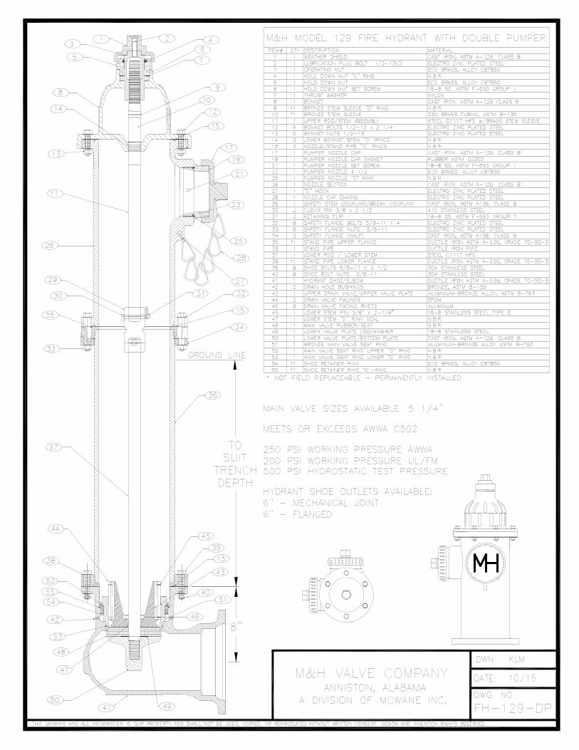
129 HYDRANT PARTS ASSEMBLYITEM NO. DESCRIPTION MATERIAL QTY.
2 Hold Down Nut Set Screw Stainless Steel 1
3 Lubricating Bolt Zinc Plated Steel 1
4 Weathershield Cast Iron 1
5 Hold Down Nut Brass Alloy C87850 1
6 Hold Down Nut O-Ring #331 EPDM 1
7 Operating Nut Brass Alloy C87850 1
8 Thrust Washer Acetal 1
9 Upper Rod Steel C1117 HFS w/ Brass Stem Sleeve 1
10 Bonnet Hex Bolts Zinc Plated Steel 6
11 Bonnet Cast Iron 1
12 Rod O-Rings #218 Buna-N 2
13 Bonnet/Nozzle/Standpipe O-Ring #370 Buna-N 3
14 Nozzle Section Cast Iron 1
15 Bonnet Hex Nuts Zinc Plated Steel 6
16 Hose Nozzle O-Ring #234 Buna-N 2
17 Hose Nozzle Brass Alloy C87850 2
18 Hose Cap Gasket Rubber 2
19 Hose Cap Cast Iron 2
20 Hose Nozzle Set Screw Stainless Steel 2
21 Pumper Nozzle Set Screw Stainless Steel 1
22 Pumper Nozzle O-Ring #250 Buna-N 1
23 Pumper Nozzle Brass Alloy C87850 1
24 Pumper Cap Gasket Rubber 1
25 Pumper Cap Cast Iron 1
26 Retaining Clips Stainless Steel 2
27 Clevis Pins Stainless Steel 2
28 Break Coupling Cast Iron 1
29 Safety Flange Bolts Zinc Plated Steel 8
30 Safety Flange Cast Iron 2
31 Safety Flange Nuts Zinc Plated Steel 8
32 Stand Pipe S/A Ductile Iron 1
33 Lower Rod Steel C1117 HF5 1
34 Lower Rod Pin Stainless Steel 1
35 Upper Valve Plate Aluminum Bronze Alloy 1
36 Drain Valve Rivets Stainless Steel 8
37 Drain Valve Facing EPDM 2
38 Seat Ring Upper O-Ring #261 Buna-N 1
39 Seat Ring Aluminum Bronze Alloy 1
40 Seat Ring Lower O-Ring #255 Buna-N 1
41 Lower Rod O-Ring #020 Buna-N 1
42 Main Valve Seat Buna-N 1
43 Bottom Plate Lock Washer Stainless Steel 1
44 Bottom Plate Cast Iron 1
45 Shoe Hex Bolts Stainless Steel 8
46 Shoe/Retainer Ring S/A Ductile Iron/Brass Alloy C87850 1
47 Shoe Hex Nuts Stainless Steel 8
48 Drain Hole Bushing Bronze 2
49 S-Hook (not shown) Zinc Plated Steel 1
50 Chain (not shown) Zinc Plated Steel 3
33
34
35
36
37
38
39
40
41
42
43
44
26
7
27
8
28
9
3
4
5
6
10
11
12
13
13
13
30
31
32
45
46
47
48
14
15
16
20
29
21
2223
2425
1718
19
2

ENGINEERING FEATURES
MOISTURE PROTECTIONDurable cast iron weather cap
combines with one piece copper alloy operating nut and O-rings to provide
reliable, corrosion-free operation under all weather conditions.
LUBRICATION RESERVOIRO-ring sealed reservoir may be filled with grease or oil through
the lubrication bolt.
TGIC Coating provides a longer-lasting,
more durable finish.
SAFETY STEM COUPLING SYSTEMBreakaway parts shear cleanly
below the top of the barrel, preventing nozzle section damage or opening of
the main valve.
BRONZE ALLOY UPPER VALVE PLATE
Solid design for added strength and durability.
BRONZE ALLOY TO BRONZE ALLOY
Bronze alloy seat ring threads into bronze alloy drain ring
for corrosion-free protection
COMPRESSION SEATINGHigh-durometer rubber valve
closes with the water pressure for a positive seal.
PADSPads on hydrant shoe give large
surface areas for standing and blocking hydrant.
ANTI-FRICTIONThrust washer above the bronze alloy thrust collar provides low-torque operation even at 250 PSI.
BRONZ ALLOY NOZZLESMechanically locked, corrosion-resistant, field replaceable bronze alloy nozzles have O-ring seals for water-tight connections.
SEALSStandard O-rings secure mating flanges throughout the 129S. All O-rings are dependable and easy to replace.
DRAIN VALVERubber valve facings provide a tight, lifelong seal. Bronze alloy seat ring has a 360 degree drain channel. Double ports flush with each use.
NUTS & BOLTSAll fasteners below grade are stainless steel.
LOWER VALVE PLATEBottoms out in the ductile iron shoe. Prevents seat from falling below the seat ring.
DUCTILE IRON HYDRANT SHOEShaped for low turbulence and maximum flow, the shoe is offered in a variety of end connections. Comes standard with epoxy coating inside and out.

ACCESSORIES
SEAT REMOVAL WRENCH — A light-weight universal combination tool is used to remove the main valve components. The bronze alloy seat ring unthreads from the drain ring by engaging the wrench at the bottom of the break coupling.
HOLD DOWN NUT WRENCH — The wrench fits the hold down nut for easy removal.
LUBRICATION — The hydrant features a dual lubrication system. Simply add grease or oil by removing the lubrication bolt on top of the weathershield.
EXTENSION KIT — Contains everything required to extend the stem and barrel. Available in 6" increments.
SAFETY FLANGE REPAIR KIT — Includes safety flanges, stem coupling, pins and clips, flange O-rings, all bolts, nuts, and hardware to repair a hydrant damaged by a traffic accident.
MAIN VALVE SEAT REPAIR KIT — Contains drain valve facings, SS rivets, main valve seat, lock washer, and all required O-rings.
RECOMMENDED SPECIFICATIONS
1. Fire hydrant shall be manufactured in accordance with AWWA standard C502, utilizing dry barrel dry top design.
2. Fire hydrant shall be rated at 250 PSI working pressure and tested to 500 PSI hydrostatic pressure.
3. Fire hydrant shall be of dual lubrication design featuring a lubrication bolt in the top of the weathershield for oil or grease.
4. Fire hydrant shall feature o-ring seals at the bonnet, break line, and elbow.
5. The traffic break coupling shall be comprised of cast iron with the seat wrench mounting-point located on the squared bottom.
6. Break flanges shall be made of cast iron and allow 360 degrees of rotation.
7. The nozzle section and one piece bonnet shall be comprised of cast iron coated in durable polyester powder coat.
8. Nozzles shall be threaded and screwed into the nozzle section and mechanically secured with a set screw.
9. The stand pipe and elbow shall be comprised of ductile iron utilizing stainless steel bolts/nuts below ground level.
10. The upper drain valve shall consist of bronze alloy and contain rubber facings secured in place by stainless steel rivets.
11. The seat ring shall be comprised of bronze alloy and utilize a double O-ring seal.
12. Fire hydrant shall be manufactured with a one piece bottom plate that limits travel in the elbow of the hydrant and is secured in place by a lock washer on the lower stem threading.
13. Fire hydrant shall be the M&H model 129 manufactured by M&H Valve Co.
PRODUCT DATA
*Nozzle height ground line

ALUMINUM BRONZE CLAPPER WITH RESILIENT SEAT
Threats to the water supply can come from either accidental or deliberate acts. Our nation’s water superintendents have safeguarded nearly all of the access points to our drinking water. At this time, one critical access point is left unprotected — the fire hydrant.
The Patriot hydrant check valve prevents reverse flow through the fire hydrant, safely protecting our drinking water while providing a full-port unobstructed waterway that allows firefighters access to the water they need when they need it.
Unlike locks and special external devices, the Patriot is installed underground, which prevents tampering and allows the hydrant to be operated the moment the firefighters arrive on the scene. The Patriot can be installed on any 6" mechanical joint connection, ensuring compatibility with all hydrant brands — providing the flexibility and cost-effectiveness you demand.
PATRIOT HYDRANT CHECK VALVEGUARD YOUR WATER SYSTEM FROM ACCIDENT OR ATTACK

RECOMMENDED SPECIFICATIONS (OPTIONAL)
1. The check valve shall be manufactured to all of the testing and performance standards of AWWA C508 and AWWA C550. The check valve shall be designed for 250 PSI working pressure and tested to 500 PSI hydrostatic pressure.
2. The check valve shall be a standalone unit able to be positively restrained to any 6" mechanical joint fire hydrant shoe.
3. The check valve shall be ductile iron ASTM Standard A536 (70-50-05) with NSF-approved fusion-bonded epoxy coating (interior/exterior).
4. The check valve shall be lead free, with no exposed lead-bearing surfaces.
5. The check valve shall have an unobstructed waterway. No reduction of port or redirection of flow will be allowed.
6. The seat shall be retained via a double dove tail O-ring, retaining groove design to ensure a positive seal.
7. The check valve shall incorporate integral positive restraint connections that maintain a restrained connection between the fire hydrant and the gate valve.
8. The check valve shall incorporate a stainless steel spring that hastens positive closure and prevents water hammer.
9. All fasteners shall be 304 stainless steel, and all interior rubber components shall be EPDM rubber.
10. The check valve shall be produced with no less than 80% post consumer recycled content while being cast, manufactured, assembled, and tested in the United States.
605 West 23rd StreetAnniston, AL 36201 Ph 256-237-3521Fx 256-741-6253
V1.52417
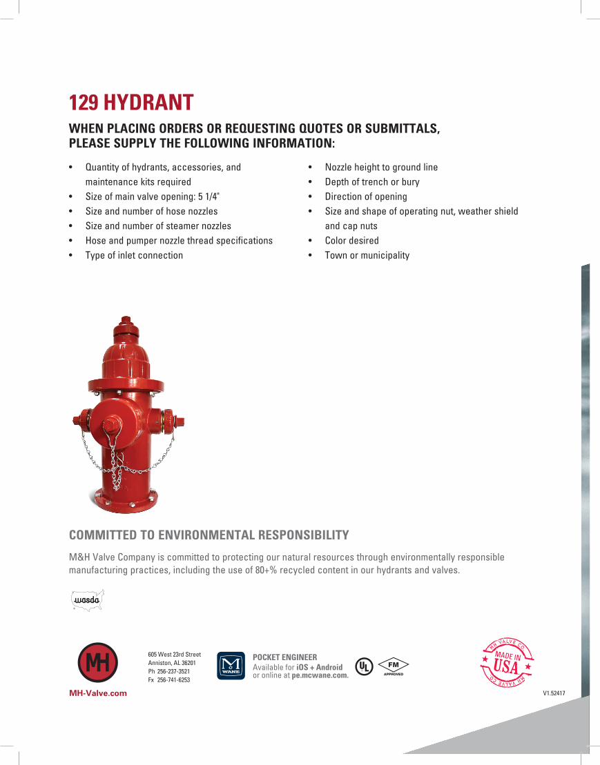
COMMITTED TO ENVIRONMENTAL RESPONSIBILITY
M&H Valve Company is committed to protecting our natural resources through environmentally responsible manufacturing practices, including the use of 80+% recycled content in our hydrants and valves.
MH-Valve.com
129 HYDRANTWHEN PLACING ORDERS OR REQUESTING QUOTES OR SUBMITTALS, PLEASE SUPPLY THE FOLLOWING INFORMATION:
• Quantity of hydrants, accessories, and maintenance kits required
• Size of main valve opening: 5 1/4"• Size and number of hose nozzles• Size and number of steamer nozzles• Hose and pumper nozzle thread specifications• Type of inlet connection
• Nozzle height to ground line• Depth of trench or bury• Direction of opening• Size and shape of operating nut, weather shield
and cap nuts• Color desired• Town or municipality
POCKET ENGINEERAvailable for iOS + Android or online at pe.mcwane.com.

GENERAL FEATURES / GENERAL SPEC
M&H AWWA C502 FIRE HYDRANTS Model 129 Traffic Model 250 PSI Working Pressure – 500 PSI Hydrostatic Test – AWWA UL / FM Approved
Type: Compression type, opening against line pressure. Main valve will remain closed should hydrant be broken off by traffic accident. Classification and Size: Hydrants are classified by the main valve size, number and size of hose and pumper nozzles. Hydrant sizes are designated as 4 ½ and 5 ¼ inches, size being the inside diameter of the main valve seat opening. Length: Hydrant lengths are determined by depth of trench below ground level. Lengths are in multiples of six inches. Barrel: Upper section of barrel (nozzle section) contains the hose and pumper nozzles. The water way is uniform in diameter for entire length of barrel. Hydrant Inlet: Hydrant shoe or elbow is provided with flange or mechanical joint connection to fit connecting pipe. All shoe types except flanged are provided with lugs for strapping. The two drain openings in the hydrant shoe are bronze bushed. All shoes are protected from corrosion with fusion bonded epoxy coating. Hose and Pumper Nozzles: Threaded with fine thread and screwed (no quarter turns) into tapped openings in nozzle section of hydrant. Hose and pumper nozzle caps are provided with rubber gaskets and chained to nozzle section. Dry Top: Operating threads are isolated from the waterway by a double O-ring seal in the one piece bonnet. Operating nut has lubricating hole for lubrication of operating threads and thrust bearing.
Dry Barrel: When the valve of the hydrant is closed, two drain valves in the hydrant shoe automatically open and allow rapid and complete drainage of the hydrant barrel. This dry barrel eliminates danger of damage to the hydrant by freezing. Operating Mechanism and Working Parts: A tamper resistant cast iron weather shield protects the operating mechanism and rubber O-ring seals from environmental elements and painting solvents. The bronze operating nut drives a steel main valve rod, which is bronze sheathed where it passes through the one-piece bonnet. A bronze-to-bronze seat assembly allow for all working parts to be easily removable through the top of the hydrant without excavating. The bronze seat ring threads into a bronze retainer ring bushing, which is permanently affixed into the shoe. The dual positive acting drain valve is constructed of a high strength aluminum bronze to provide additional strength for operation and disassembly. The rubber drain valve facings are water pressure activated and effectively eliminate the drain valve as a maintenance issue. Component Materials: All gray iron parts conform to ASTM A-126, Class B. Ductile Iron components conform to ASTM A536. All non-corrosive metal parts are made of copper alloys conforming to AWWA Standard C502 requirements. Remaining components are performance selected from some of the highest quality materials available today. Shop Tests: Main valve tested from inlet side to 250psi. With main valve open, drain valve and entire hydrant, hydrant hydrostatic pressure tested to 500psi.
September 2012 / M&H C502 / Model 129

FEATURES AND BENEFITS
M&H AWWA C502 MODEL 129 FIRE HYDRANTS YESTERDAY, TODAY, AND TOMORROW----An American Company with an American made product. M&H has been around since 1854 and have been producing hydrants since 1929. We back up our M&H 129 Fire Hydrants with a 10 Year Limited Warranty. (1) WEATHER SHIELD---One-piece cast iron component deflects moisture and dust exposure to bronze stem nut. Affords protection against freezing conditions ensuring operational efficiency. Protects bronze operating nut from pipe wrench damage commonly seen on all bronze actuated hydrants. (2) LUBRICATION PLUG BOLT---Firmly attaches operating nut / weather shield unit to bronze stem nut. Bolt fits flush with top of weather shield causing it to be tamper resistant. Using Allen wrench, plug is easily removed for field servicing or maintenance. (3) BRONZE OPERATING NUT---Primary operating component. Is a heavy duty design. Ample amounts of brass along the throat of nut. (4 & 5) HOLD DOWN NUT---Non-corrodible bronze nut secures stem nut for operating thrusts. Lock nut provides additional weather protection with threading attachment to bonnet and large O-ring seal. (6) HOLD DOWN NUT SET SCREW Stainless Steel set screw keeps hold down nut from backing out during operation. Is removed / re-installed with Allen wrench. (7) NYLON THRUST WASHER---Nylon antifriction bearing at thrust collar reduces operating torque up to 40% for smoother open / close cycles. Standard on 5 ¼” hydrants (8, 14, & 15) BONNET DESIGN / HYDRANT DUAL LUBRICATION With the single unit design, an M&H 129 Fire Hydrant customer is afforded the option of using either grease or oil as an operating mechanism lubricant. Standard factory procedure is to lubricate with grease. Oil is easily substituted in field by removing lubrication plug bolt. Two O-ring seals in bonnet prevents pressurized water from entering and lubricant from escaping into the hydrant. Bonnet flange ring gives finished appearance at bonnet / nozzle section flange. Prevents dirt build-up between flanges. Hidden flange connection sealed with heavy O-ring. (11) UPPER STEM ASSEMBLY---High strength steel stem has rugged acme threads at top end to match threads in bronze stem nut. Brass stem sleeve is machined fitted on segment that penetrates grease / oil reservoir providing smooth, non-corrodible bearing surface for double O-ring seals. O-ring inset between sleeve and stem provides additional leakage protection. (22, 23, 24, & 25) BRASS NOZZLES / NOZZLE O-RINGS---Hose and pumper nozzles are machine threaded into nozzle outlets, an original M&H design. They are easily removed for field replacement. Nozzle leak protection afforded by O-ring behind each nozzle. (20 & 21) NOZZLE SET SCREWS---Nozzles are firmly set into place by stainless steel set screw. Prevents turning of nozzle during hose coupling attachment or removal. If nozzles ever need to be replaced, setscrew can be removed using standard Allen wrench. (26) NOZZLE SECTION---Molded from durable cast iron and available with either two hose and one pumper nozzle or two hose nozzles. Has generous cross-sectional area and smoothly contoured hose outlets to deliver maximum available flow. Entire nozzle section coated with a fusion bonded polyester (26) NOZZLE SECTION 360 ROTATION / ALIGNMENT--- Above ground hydrant assembly may be rotated full 360 degrees on the standpipe flange to improve alignment to curb. This is accomplished without dismantling. Simply loosen flange bolts, rotate and re-tighten.
(34) TRAFFIC IMPACT PROTECTION---Upon vehicular impact, two lower safety flange rings fracture and stem couple separates below break line. This allows the above ground hydrant assembly to separate cleanly from standpipe and keeps accidental opening of hydrant from vehicle tire. Repair is easily accomplished with economical field repair kit. (15) O-RING SEALS---Heavy Duty O-Rings provides superior sealing contact between standpipe flange joints. O-ring at break joint makes hydrant rotation easier than traditional flat gaskets. (29) TRAFFIC STEM COUPLING---Designed to break from collision without damage to main valve or rod assembly. Bottom half of coupling is square and accepts short disassembly wrench. Square design provides a direct drive area below break area for main valve seat removal and maintenance. (36) DUCTILE IRON STANDPIPE---Fabricated for exceptional strength and support below grade. HYDRANT EXTENSIONS---M&H 129 Fire Hydrants may be lengthened where ground level is being raised without digging up hydrant or requiring complete new barrel. Simply add an M&H hydrant extension available in 6” increments to the existing standpipe. (43, 44, & 45) UPPER DRAIN VALVE---Made of high strength aluminum-bronze alloy Includes double drains with rubber facings. Design provides positive closure of two bronze-bushed drain ports during operation. After operation, the drain valve quickly drains all water from the standpipe preventing cold weather freeze-up. Drain ports are purged during first three operating turns on opening and again on closing. (51) BRONZE MAIN VALVE SEAT RING---Generous amount of material and contoured design provide smooth flow and low-pressure drop. (54) BRONZE SHOE RETAINER RING----Permanently affixed to hydrant shoe with O-ring seal. Shoe Retainer Ring provides a bronze-to-bronze interface with the Main Valve Seat Ring for years for easy seat disassembly. (41) HYDRANT SHOE / ELBOW---Ductile iron hydrant shoe designed to provide smooth, even flow around valve assembly assuring highest possible flow through main valve. Coated internal and externally with fusion bonded epoxy that meets AWWA C550 standards. Provides corrosion resistance to water or soil. Mechanical Joint shoes come standard with strapping lugs for restraining hydrant shoe to pipeline. (49 & 50) LOCK WASHER / BOTTOM PLATE---Bottom plate is single component made from cast iron. Bottom plate compresses lock washer and rubber seat against top plate and securely attaches valve assembly to lower operating stem. Bottom plate is coated with same fusion bonded epoxy applied to shoe. PARTS INTERCHANGABILITY---Several design and material improvements have been made to the current Style 129 Fire Hydrant. In no case have any changes sacrificed interchangeability. Parts produced today will work on M&H hydrants produced since 1929. VALVE DISASSEMBLY---Disassembly of internal valve is achieved with the use of a Short Disassembly Wrench that engages the square end of our traffic coupling. No large removal wrench needed. VALVE OPENING SELECTION---We offer the choice between a 4 ½” and 5 ¼” valve opening on our 129 fire hydrants.
APPROVALS---M&H 129 Fire Hydrants meet or exceed AWWA C502. Underwriters Laboratory and Factory Mutual approvals. TESTING---M&H 129 Fire Hydrants are individually seat tested at 250 psi followed by a 500 psi shell test to assure material and seal quality.
September 2012 / M&H C502 / Model 129

SUGGESTED SPECIFICATIONS (1 of 2)
M&H AWWA C502 FIRE HYDRANTS Model 129 Traffic Model 250 PSI Working Pressure – 500 PSI Hydrostatic Test - AWWA UL / FM Approved _______________________________________________________________________________________ GENERAL Fire hydrants shall comply in all respects with AWWA Standard C-502, latest revision. Fire hydrants shall
be of the compression type, with the main valve opening against the pressure and closing with the pressure. The main valve opening shall be (4 ½” or 5 ¼”) in diameter. Fire Hydrant shall be of a dry barrel, dry top design. The nozzle section shall consist of two (2) hose nozzles and one (1) pumper nozzle or other as specified.
_______________________________________________________________________________________ RATING Fire hydrants shall be rated at 250 psi water working pressure, tested at 500 pounds hydrostatic for
structural soundness in the following manner: 500 pound hydrostatic test supplied from the inlet side, first with the main valve closed for the testing of the valve seat: second, with the main valve open for testing of the drain valves and the hydrant barrel. Testing to be complete in accordance with AWWA C-502 and UL & FM requirements.
_______________________________________________________________________________________ END Hydrants shall be connected to the main by a 4” or 6” fusion bonded, epoxy coated mechanical joint or CONFIGURATION flanged shoe. Mechanical joint shoes shall be fitted with strapping lugs. _______________________________________________________________________________________ DESIGN The main valve seat of the hydrant shall be made of rubber and be supported by a one-piece bronze top
plate / drain valve mechanism. Drain valve shall have replaceable rubber facings.
The bottom stem threads of the main valve rod shall be fitted with an epoxy coated, cast iron bottom plate, sealing lower rod threads from the water.
Changes in size or shape of the waterway (hydrant nozzles) shall be accomplished by means of easy curves. Exclusive of the main valve opening, the net area of the waterway of the barrel and the foot piece at the smallest part shall not be less than 120% of that of the net opening of the main valve.
Hose and pumper nozzles shall be threaded and screwed into the nozzle section. And then mechanically locked to prevent turning.
Hose and pumper caps shall be chained to the hydrant
The hydrant shall be so designed that when it is in place, no excavation will be required to remove the main valve and movable parts of the drain valve. Further, the hydrant shall be of the type that can be extended without excavating. Hydrants shall be so designed that, in the event of accident, or breaking of the hydrant above or near grade level; the main valve will remain closed. The main valve rod shall be made in two parts and fitted with breakable coupling at the ground line flange.
The ground line connection between nozzle section and the barrel shall incorporate the use of two traffic flange. This connection shall be so designed that the nozzle section can be rotated in any increment of 360. The ground line connection between the barrel and nozzle sections shall have a rubber o-ring gasket to provide a seal.
The operating threads of the hydrant shall be so designed as to avoid the working of any iron or steel parts against either iron or steel. The operating stem and operating nut threads shall be square or acme type.
September 2012 / M&H C502 / Model 129

SUGGESTED SPECIFICATIONS (2 of 2) . DESIGN The operating thread shall be lubricated at factory with food grade grease. Access shall be provided (Continued) to field lubricate the operating mechanism.
The operating thread shall be sealed from water at all times when the valve is either in the opened or closed position. The operating rod shall be bronze sheathed where it passes through the double “O” ring
seal in the bonnet.
The bonnet shall be weather proof and utilize a weather shield integral with the external wrench operating nut.
The operating nut shall be made of bronze with a self-lubricating design.
Hydrants shall be of the dry barrel type and hydrant shoe shall have two positive acting non-corrosive drain valves that shall drain the hydrant completely by opening when the main valve is closed, and close tightly in accordance with AWWA C-502 requirements when main valve is open.
The main valve assembly shall be seated in the hydrant with a bronze-to-bronze interface to facilitate removal of the main valve, should maintenance be required. The nozzle section shall consist of two-2 1/2” hose nozzles to the specified thread designation (NST or other, as specified) and one pumper nozzle 4 ½” in diameter to the specified thread designation (NST or other, as specified), or other combination of nozzle outlets, including independent hose gate valves, as specified.
Two O-ring seals shall be utilized where the main hydrant rod passes through the 1 piece bonnet.
Hydrant standpipe shall be ductile iron and single piece for all bury depths.
All like parts of hydrants of the same size and model produced by the same manufacturer shall be inter-changeable.
Hydrant shall open by turning to the (left or right). Direction of opening to be permanently marked on hydrant bonnet.
Threads on hose and steamer nozzles shall be National Standard unless otherwise specified.
Size and shape of operating nuts cap nuts shall conform to National Standard unless otherwise specified.
Bury shall be (specify depth of bury) measuring depth from grade line to bottom of trench or connecting pipe.
Auxiliary shut-off (isolation) gate valves, when required, shall be of the same manufacture as the hydrant.
_______________________________________________________________________________________ COATING Hydrant shoes shall have an interior and exterior thermosetting epoxy coating of 5 to 6 mils meeting
AWWA C550. Exterior of hydrant nozzle section shall be Fire Hydrant Red (or as specified). _______________________________________________________________________________________ MARKINGS Hydrant shall be marked with the name of the manufacturer, size of valve opening, direction of opening
and the year of manufacture all in accordance with the AWWA C-502. Country of origin to be cast on all major hydrant castings.
_______________________________________________________________________________________ SOURCE Hydrants shall be M&H Model 129 or approved equal
September 2012 / M&H C502 / Model 129

M&H VALVE COMPANY Anniston, Alabama
M&H C502 Fire Hydrants
TEN-YEAR LIMITED WARRANTY M&H Valve Company warrants that its AWWA C502 Fire Hydrant will be free from defects in material and workmanship under normal and customary use and maintenance for a period of ten (10) years from the date of purchase, provided the hydrant is installed and maintained according to M&H instructions, and applicable codes. The foregoing warranty does not cover failure of any part or parts from external forces, including, but not limited to, earthquake, vandalism, vehicular or other impact, application of excessive torque to the operating mechanism or frost heave. Should any M&H Valve Company part or parts fail to conform to the foregoing warranty, M&H shall, upon prompt written notice thereof, repair or replace, F.O.B. point of manufacture, such defective part or parts. Purchaser shall, if requested, return the part or parts to M&H, transportation prepaid. Purchaser shall bear all responsibility and expense incurred for removal, reinstallation and shipping in connection with any part supplied under the foregoing warranty. THE FOREGOING WARRANTY IS IN LIEU OF AND EXCLUDES ALL OTHER WARRANTIES NOT EXPRESSLY SET FORTH HEREIN, WHETHER EXPRESS OR IMPLIED BY OPERATION OF LAW OR OTHERWISE, INCLUDING, BUT NOT LIMITED TO, ANY WARRANTIES OF MERCHANTABILITY OR FITNESS. IN NO EVENT SHALL M&H VALVE COMPANY BE RESPONSIBLE OR LIABLE FOR ANY INCIDENTAL OR CONSEQUENTIAL LOSSES, DAMAGES, OR EXPENSES.
September 2012 / M&H C502 Fire Hydrants