11101 always cat 2005 - bearing
TRANSCRIPT
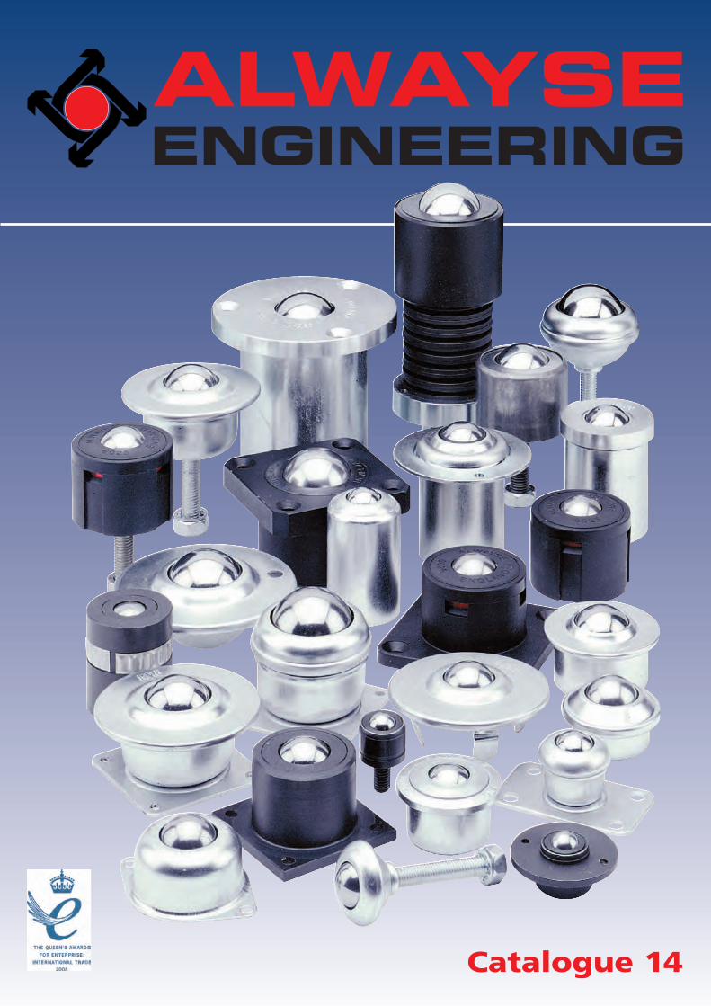
Catalogue 14
ALWAYSEENGINEERING
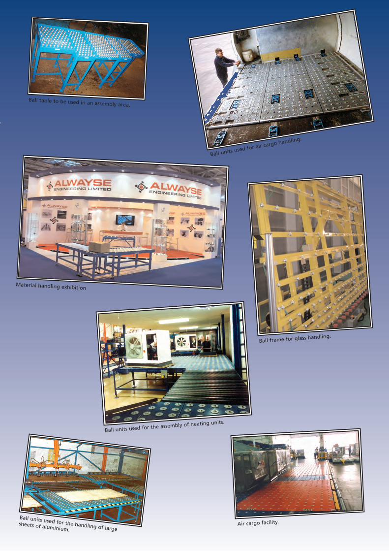
Ball units used for the assembly of heating units.
Material handling exhibition
Ball units used for air cargo handling.
Ball table to be used in an assembly area.
Ball units used for the handling of largesheets of aluminium.
Ball frame for glass handling.
Air cargo facility.
Resin transfer moulds in theaerospace industry.
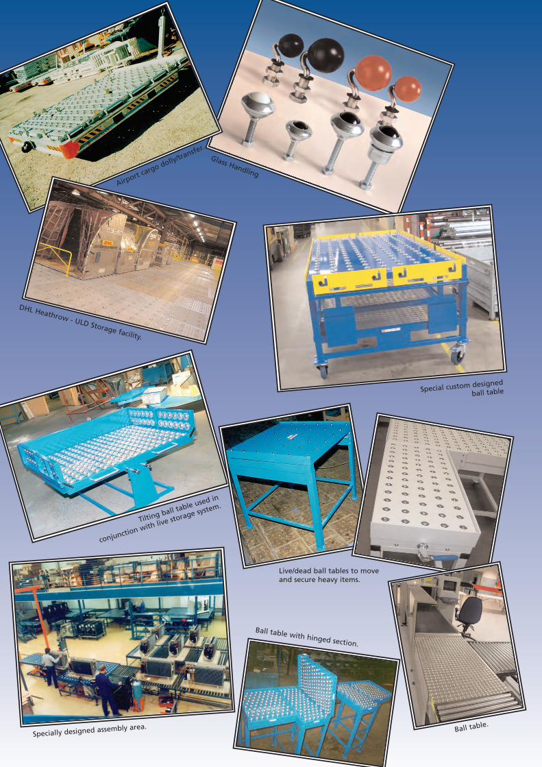
Airport cargo dolly/tra
nsfer.
Ball table with hinged section.
DHL Heathrow - ULD Storage facility.
Specially designed assembly area.
Tilting ball table used in
conjunction with live storage system.
Special custom designed
ball table
Glass Handling
Live/dead ball tables to moveand secure heavy items.
Ball table.
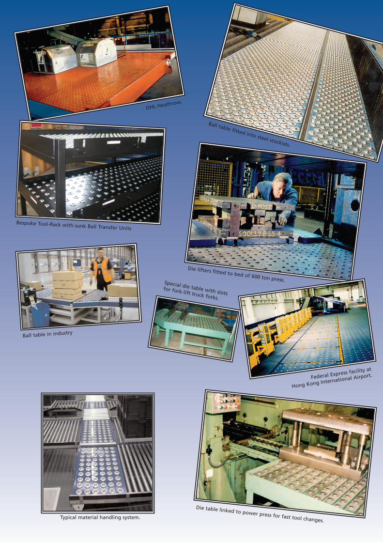
Ball table in industry
Bespoke Tool-Rack with sunk Ball Transfer Units
Federal Express facility at
Hong Kong International Airport.
Ball table fitted into steel stockists.
Die lifters fitted to bed of 600 ton press.
Die table linked to power press for fast tool changes.
DHL Heathrow.
Special die table with slotsfor fork-lift truck forks.
Typical material handling system.
ALWAYSE ENGINEERING LIMITED - TERMS AND CONDITIONS OF SALE
1 Interpretation
1.1 In these Terms Conditions:
“COMPANY” means Alwayse EngineeringLimited
“CONTRACT” means the contract for thepurchase and sale of the Goods
“CUSTOMER” means the person or companywho accepts a quotation of the Company for the saleof the Goods, or whose order for the Goods is accept-ed by the Company
“GOODS” means the goods which the Company is tosupply in accordance with these Terms and Conditions
1.2 Any reference in these Terms andConditions to any provision of a statute shall be con-strued as a reference to that provision as amended, re-enacted or extended at the relevant time.
2 Basis of the Sale
2.1 The Company shall sell and the Buyer shallpurchase the Goods in accordance with any writtenquotation of the Company which is accepted by theBuyer within 60 days of its date, or any written orderof the Buyer which is accepted by the Company, sub-ject in either case to these Terms and Conditions,which shall govern this Contract to the exclusion ofany other terms and conditions subject to which anysuch quotation is accepted or purported to be accept-ed, or any such order is made or purported to bemade, by the Buyer.
2.2 No order submitted by the Buyer shall bedeemed to be accepted by the Company unless anduntil confirmed in writing by the Company’s autho-rised representative.
3 Price of the Goods
3.1 The price of the Goods shall be theCompany’s quoted price or, where no price has beenquoted (or a quoted price is no longer valid), the pricelisted in the Company’s published price list current atthe date of delivery of the Goods
3.2 The Company reserves the right, by givingnotice to the Buyer at any time before delivery, toincrease the price of the Goods to reflect any increasein the cost to the Company which is due to any factorbeyond the control of the Company.
3.3 The price is exclusive of delivery, handling,administration and packaging charges and any applic-able value added tax, which the Buyer shall be addi-tionally liable to pay to the Company.
4 Delivery
4.1 Unless otherwise provided in the Contract,delivery of the Goods shall be made by the Companyat the Buyer’s premises
4.2 The Contract price does not include thecost of off-loading and assembly, which shall bearranged by the Buyer and performed at its ownexpense and risk unless otherwise agreed in writing.
4.3 Any dates quoted for delivery of theGoods are approximate only and the Company shallnot be liable for any delay in delivery of the Goodsbut shall use its reasonable endeavours to deliver onthe quoted date. Time for delivery shall not be of theessence of the Contract
4.4 If the Buyer does not accept delivery whentendered by the Company the Buyer shall be liable forany storage, administration, carriage and re-deliverycharges.
5 Risk and Property
5.1 Risk of damage to or loss of the Goodsshall pass to the Buyer:
5.1.1 in the case of Goods to be delivered at theCompany’s premises, at the time when the Companynotifies the Buyer that the Goods are available for col-lection; or
5.1.2 in the case of Goods to be delivered other-wise than at the Company’s premises, at the time ofdelivery or, if the Buyer wrongfully fails to take deliv-ery of the Goods, the time when the Company hastendered delivery of the Goods
5.2 Notwithstanding delivery and the passingof risk in the Goods, or any other provision of theseTerms and Conditions, the property in the Goods shallnot pass to the Buyer until the Company has receivedin cash or cleared funds payment in full of the price ofthe Goods and all other goods agreed to be sold bythe Company to the Buyer for which payment is thendue.
5.3 Until such time as the property in theGoods passes to the Buyer, the Buyer shall hold theGoods as the Company’s fiduciary agent and bailee,and shall keep the Goods separate from those of theBuyer and third parties and properly stored, protectedand insured and identified as the Company’s property,but shall be entitled to resell or use the Goods in theordinary course of its business providing that the pro-ceeds of such sale shall be held upon trust for theCompany. Where the Buyer does sell or pledge theGoods it shall hold the proceeds of sale or charging asfiduciary agent of the Company and forward the sameto the Company upon a written request from theCompany.
5.4 Until such time as the property in theGoods passes to the Buyer (and provided the Goodsare still in existence and have not been resold), theCompany shall be entitled at any time to require theBuyer to deliver up the Goods to the Company and, ifthe Buyer fails to do so forthwith, to enter upon anypremises of the Buyer or any third party where theGoods are stored and repossess the Goods.
5.5 The Buyer shall not be entitled to pledgeor in any way charge by way of security for anyindebtedness any of the Goods which remain theproperty of the Company, but if the Buyer does so allmoneys owing by the Buyer to the Company shall(without prejudice to any other right or remedy of theCompany) forthwith become due and payable.
6 Limitation of Liability
6.1 All warranties, conditions or other termsemployed by statute or common law are excluded tothe fullest extent permitted by law.
6.2 Any claim by the Buyer which is based onany defect in the quality or condition of the Goods ortheir failure to correspond with specification shall(whether or not delivery is refused by the Buyer) benotified to the Company within 7 days from the dateof delivery or (where the defect or failure was notapparent on reasonable inspection) within 2 monthsafter delivery of the Goods. If delivery is not refused,and the Buyer does not notify the Company according-ly, the Buyer shall not be entitled to reject the Goodsand the Company shall have no liability for such defector failure, and the Buyer shall be bound to pay theprice as if the Goods had been delivered in accordancewith the Contract.
6.3 Where any valid claim in respect of any ofthe Goods which is based on any defect in the qualityor condition of the Goods or their failure to meetCompany specification is notified to the Company inaccordance with these Terms and Conditions, theCompany shall be entitled to replace the Goods (or thepart in question) free of charge or, at the Company’ssole discretion, refund to the Buyer the price of theGoods (or a proportionate part of the price), but theCompany shall have no further liability to the Buyer.
6.4 Except in respect of death or personalinjury caused by the Company’s negligence, theCompany shall not be liable to the Buyer by reason ofany representation (unless fraudulent), or any impliedwarranty, condition or other term, or any duty at com-mon law, or under the express terms of the Contract,for any indirect, special or consequential loss or dam-age (whether for loss of profit or otherwise), costs,expenses or other claims for compensation whatsoever(whether caused by the negligence of the Company, itsemployees or agents or otherwise) which arise out ofor in connection with the supply of the Goods or theiruse or resale by the Buyer, and the entire liability ofthe Company under or in connection with theContract shall not exceed the price of the Goods,except as expressly provided in these Terms andConditions.
6.5 The Company shall have no liability what-soever where the Goods have not been maintained orused in accordance with their recommended specifica-
tions and maintenance schedules as updated fromtime to time by the Company.
6.6 The Seller shall not be liable for any delayor failure attributable to any cause beyond the Seller’sreasonable control including without limitation fire,strike, act of god and embargo.
7 Terms of Payment
7.1 The Buyer shall pay the price of the Goodsin pounds sterling (without any deduction) within 30days of the date of the Company’s invoice, and thetime of payment of the price shall be of the essence ofthe Contract.
7.2 If the Buyer fails to make any payment onthe due date then, without prejudice to any otherright or remedy available to the Company, theCompany shall be entitled to:
7.2.1 cancel the Contract or suspend any furtherdeliveries to the Buyer;
7.2.2 appropriate any payment made by theBuyer to such of the Goods (or the goods suppliedunder any other contract between the Buyer and theCompany) as the Company may think fit; and
7.2.3 charge the Buyer interest (both before andafter any judgement) on the amount unpaid, at therate of 3 per cent per annum above Barclays Bank Plcbase rate from time to time, until payment in full ismade (a part of a month being treated as a full monthfor the purpose of calculating interest).
7.2.4 set of any monies due to the Buyer on anyaccount whatsoever against monies due to the Buyerfrom the Company
7.3 Where the Company agrees to invoice in acurrency other than sterling the Buyer shall be liablefor all currency conversion brokerage or other chargesand ensure that the sum payable to the Companywhen converted to pounds Sterling is not less than theamount payable in pounds sterling on the date ofquotation
8 Insolvency of Buyer
8.1 This clause applies if:
8.1.1 the Buyer makes any voluntary arrange-ment with its creditors or (being an individual or firm)becomes bankrupt or (being a company) becomes sub-ject to an administration order or goes into liquidation(otherwise than for the purposes of amalgamation orreconstruction); or
8.1.2 an encumbrancer takes possession, or areceiver is appointed, of any of the property or assetsof the Buyer; or
8.1.3 the Buyer ceases, or threatens to cease, tocarry on business; or
8.1.4 there is a change in control of the owner-ship of the Company or its shares
8.1.5 the Company reasonably apprehends thatany of the events mentioned above is about to occurin relation to the Buyer and notifies the Buyer accord-ingly.
8.2 If this clause applies then, without preju-dice to any other right or remedy available to theCompany, the Company shall be entitled to cancel theContract or suspend any further deliveries under theContract without any liability to the Buyer, and if theGoods have been delivered but not paid for, the priceshall become immediately due and payable notwith-standing any previous agreement or arrangement tothe contrary.
9 General
9.1 No waiver by the Company of any breachof the contract by the Buyer shall be considered as awaiver of any subsequent breach of the same or anyother provision.
9.2 This Contract shall be governed by thelaws of England, and the Buyer agrees to submit tothe non-exclusive jurisdiction of the English courts.
© This brochure is the copyright of Alwayse Engineering Limited and is fully protected. Nothing may be reprinted or reproducedin whole or part without the written consent of Alwayse Engineering Limited
April 2012
Alwayse Engineering Limited
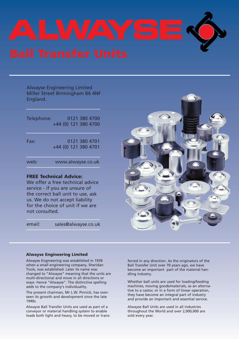
Alwayse Engineering was established in 1939 when a small engineering company, Sheridan Tools, was established. Later its name was changed to “Alwayse” meaning that the units are multi-directional and move in all directions or ways -hence “Alwayse”. The distinctive spelling adds to the company’s individuality.
The present chairman, Mr L.W. Pinnick, has over-seen its growth and development since the late1940s.
Alwayse Ball Transfer Units are used as part of aconveyor or material handling system to enableloads both light and heavy, to be moved or trans-
ferred in any direction. As the originators of theBall Transfer Unit over 70 years ago, we havebecome an important part of the material han-dling industry.
Whether ball units are used for loading/feedingmachines, moving goods/materials, as an alterna-tive to a castor, or in a form of linear operation,they have become an integral part of industryand provide an important and essential service.
Alwayse Ball Units are used in all industriesthroughout the World and over 2,000,000 aresold every year.
Ball Transfer Units
Alwayse Engineering LimitedMiller Street Birmingham B6 4NFEngland.
Telephone: 0121 380 4700+44 (0) 121 380 4700
Fax: 0121 380 4701+44 (0) 121 380 4701
web: www.alwayse.co.uk
email: [email protected]
FREE Technical Advice:We offer a free technical adviceservice - if you are unsure ofthe correct ball unit to use, askus. We do not accept liabilityfor the choice of unit if we arenot consulted.
IMPORTANT - IF YOU ARE UNSURE, CONSULT OUR FREE TECHNICAL SERVICE. Tel: +44 (0) 121 380 4700 Fax: +44 (0) 121 380 4701
TECHNICAL INFORMATION
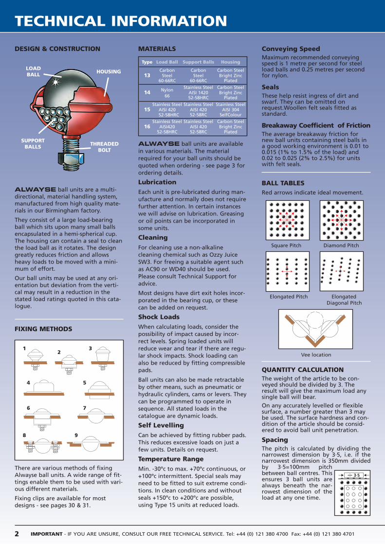
DESIGN & CONSTRUCTION
ALWAYSE ball units are a multi-directional, material handling system,manufactured from high quality mate-rials in our Birmingham factory.
They consist of a large load-bearingball which sits upon many small ballsencapsulated in a hemi-spherical cup.The housing can contain a seal to cleanthe load ball as it rotates. The designgreatly reduces friction and allowsheavy loads to be moved with a mini-mum of effort.
Our ball units may be used at any ori-entation but deviation from the verti-cal may result in a reduction in thestated load ratings quoted in this cata-logue.
FIXING METHODS
There are various methods of fixingAlwayse ball units. A wide range of fit-tings enable them to be used with vari-ous different materials.
Fixing clips are available for mostdesigns - see pages 30 & 31.
MATERIALS
ALWAYSE ball units are availablein various materials. The materialrequired for your ball units should bequoted when ordering - see page 3 forordering details.
Lubrication
Each unit is pre-lubricated during man-ufacture and normally does not requirefurther attention. In certain instanceswe will advise on lubrication. Greasingor oil points can be incorporated insome units.
Cleaning
For cleaning use a non-alkaline
cleaning chemical such as Ozzy Juice
SW3. For freeing a suitable agent such
as AC90 or WD40 should be used.
Please consult Technical Support for
advice.
Most designs have dirt exit holes incor-porated in the bearing cup, or thesecan be added on request.
Shock Loads
When calculating loads, consider thepossibility of impact caused by incor-rect levels. Spring loaded units willreduce wear and tear if there are regu-lar shock impacts. Shock loading canalso be reduced by fitting compressiblepads.
Ball units can also be made retractableby other means, such as pneumatic orhydraulic cylinders, cams or levers. Theycan be programmed to operate insequence. All stated loads in thecatalogue are dynamic loads.
Self Levelling
Can be achieved by fitting rubber pads.This reduces excessive loads on just afew units. Details on request.
Temperature Range
Min. -30ºc to max. +70ºc continuous, or+100ºc intermittent. Special seals mayneed to be fitted to suit extreme condi-tions. In clean conditions and withoutseals +150ºc to +200ºc are possible,using Type 15 units at reduced loads.
Conveying SpeedMaximum recommended conveyingspeed is 1 metre per second for steelload balls and 0.25 metres per secondfor nylon.
SealsThese help resist ingress of dirt andswarf. They can be omitted onrequest.Woollen felt seals fitted asstandard.
Breakaway Coefficient of FrictionThe average breakaway friction for new ball units containing steel balls ina good working environment is 0.01 to0.015 (1% to 1.5% of the load) and0.02 to 0.025 (2% to 2.5%) for unitswith felt seals.
BALL TABLESRed arrows indicate ideal movement.
Square Pitch Diamond Pitch
Elongated Pitch ElongatedDiagonal Pitch
Vee location
QUANTITY CALCULATIONThe weight of the article to be con-veyed should be divided by 3. Theresult will give the maximum load anysingle ball will bear.
On any accurately levelled or flexiblesurface, a number greater than 3 maybe used. The surface hardness and con-dition of the article should be consid-ered to avoid ball unit penetration.
SpacingThe pitch is calculated by dividing thenarrowest dimension by 3·5, i.e. if thenarrowest dimension is 350mm dividedby 3·5=100mm pitchbetween ball centres. Thisensures 3 ball units arealways beneath the nar-rowest dimension of theload at any one time.
Type Load Ball Support Balls Housing
Carbon Carbon Carbon Steel13 Steel Steel Bright Zinc
60-66RC 60-66RC Plated
Nylon Stainless Steel Carbon Steel14
66AISI 1420 Bright Zinc52-58HRC Plated
Stainless Steel Stainless Steel Stainless Steel15 AISI 420 AISI 420 AISI 304
52-58HRC 52-58RC SelfColour
Stainless Steel Stainless Steel Carbon Steel16 AISI420 AISI 420 Bright Zinc
52-58HRC 52-58RC Plated
LOADBALL HOUSING
THREADEDBOLT
SUPPORTBALLS
12
3
4 5
6 7
8 9
2
3·5
TEC
HN
ICA
L I
NFO
RM
ATIO
N
Tel: +44 (0) 121 380 4700 Fax: +44 (0) 121 380 4701 [email protected] www.alwayse.co.uk
QUICK GUIDE TO THEPRODUCT RANGE
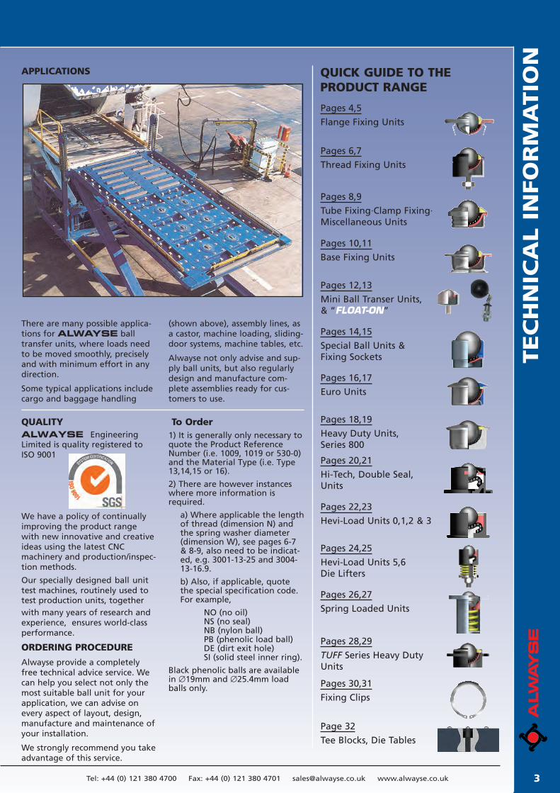
APPLICATIONS
There are many possible applica-tions for ALWAYSE balltransfer units, where loads needto be moved smoothly, preciselyand with minimum effort in anydirection.
Some typical applications includecargo and baggage handling
(shown above), assembly lines, asa castor, machine loading, sliding-door systems, machine tables, etc.
Alwayse not only advise and sup-ply ball units, but also regularlydesign and manufacture com-plete assemblies ready for cus-tomers to use.
QUALITY
We have a policy of continually improving the product range with new innovative and creative ideas using the latest CNC machinery and production/inspec-tion methods.
Our specially designed ball unit test machines, routinely used to test production units, togetherwith many years of research andexperience, ensures world-classperformance.
ORDERING PROCEDURE
Alwayse provide a completelyfree technical advice service. Wecan help you select not only themost suitable ball unit for yourapplication, we can advise onevery aspect of layout, design,manufacture and maintenance ofyour installation.
We strongly recommend you takeadvantage of this service.
To Order1) It is generally only necessary toquote the Product Reference Number (i.e. 1009, 1019 or 530-0) and the Material Type (i.e. Type 13,14,15 or 16).
2) There are however instanceswhere more information isrequired.
a) Where applicable the lengthof thread (dimension N) andthe spring washer diameter(dimension W), see pages 6-7& 8-9, also need to be indicat-ed, e.g. 3001-13-25 and 3004-13-16.9.
b) Also, if applicable, quotethe special specification code.For example,
NO (no oil)NS (no seal)NB (nylon ball)PB (phenolic load ball)DE (dirt exit hole)SI (solid steel inner ring).
Black phenolic balls are availablein ∅19mm and ∅25.4mm loadballs only.
Pages 4,5
Flange Fixing Units
Pages 6,7
Thread Fixing Units
Pages 10,11
Base Fixing Units
Pages 12,13
Mini Ball Transer Units,& “FLOAT-ON”
Pages 8,9
Tube Fixing·Clamp Fixing·Miscellaneous Units
Pages 16,17
Euro Units
Pages 20,21
Hi-Tech, Double Seal,Units
Pages 22,23
Hevi-Load Units 0,1,2 & 3
Pages 24,25
Hevi-Load Units 5,6Die Lifters
Pages 28,29
TUFF Series Heavy DutyUnits
Pages 18,19
Heavy Duty Units,Series 800
Pages 26,27
Spring Loaded Units
Pages 14,15
Special Ball Units &Fixing Sockets
Pages 30,31
Fixing Clips
Page 32
Tee Blocks, Die Tables
3
ALWAYSE EngineeringLimited is quality registered to ISO 9001
IMPORTANT - IF YOU ARE UNSURE, CONSULT OUR FREE TECHNICAL SERVICE. Tel: +44 (0) 121 380 4700 Fax: +44 (0) 121 380 47014
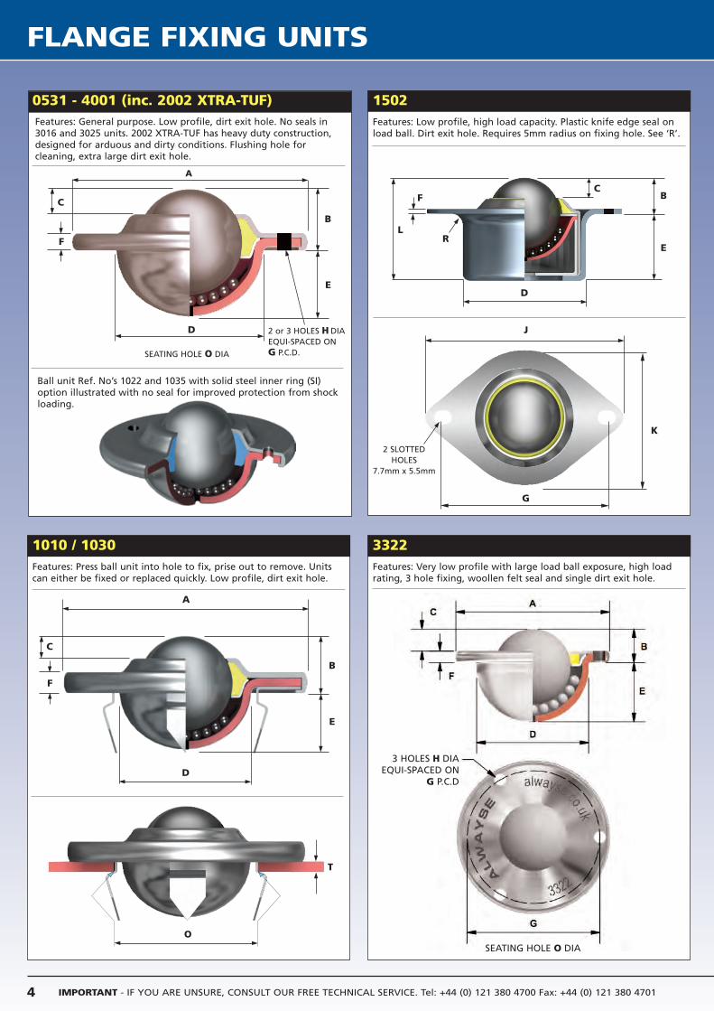
FLANGE FIXING UNITS
0531 - 4001 (inc. 2002 XTRA-TUF)Features: General purpose. Low profile, dirt exit hole. No seals in3016 and 3025 units. 2002 XTRA-TUF has heavy duty construction,designed for arduous and dirty conditions. Flushing hole for cleaning, extra large dirt exit hole.
1010 / 1030Features: Press ball unit into hole to fix, prise out to remove. Unitscan either be fixed or replaced quickly. Low profile, dirt exit hole.
Ball unit Ref. No’s 1022 and 1035 with solid steel inner ring (SI)option illustrated with no seal for improved protection from shockloading.
1502Features: Low profile, high load capacity. Plastic knife edge seal onload ball. Dirt exit hole. Requires 5mm radius on fixing hole. See ‘R’.
3322Features: Very low profile with large load ball exposure, high loadrating, 3 hole fixing, woollen felt seal and single dirt exit hole.
A
C
F
B
E
D
SEATING HOLE O DIA
2 or 3 HOLES H DIAEQUI-SPACED ONG P.C.D.
2 SLOTTEDHOLES
7.7mm x 5.5mm
L
B
E
CF
D
K
J
G
R
A
C
F
B
E
T
D
O
3 HOLES H DIAEQUI-SPACED ON
G P.C.D
SEATING HOLE O DIA
FLA
NG
E F
IXIN
G U
NIT
S
5Tel: +44 (0) 121 380 4700 Fax: +44 (0) 121 380 4701 [email protected] www.alwayse.co.uk
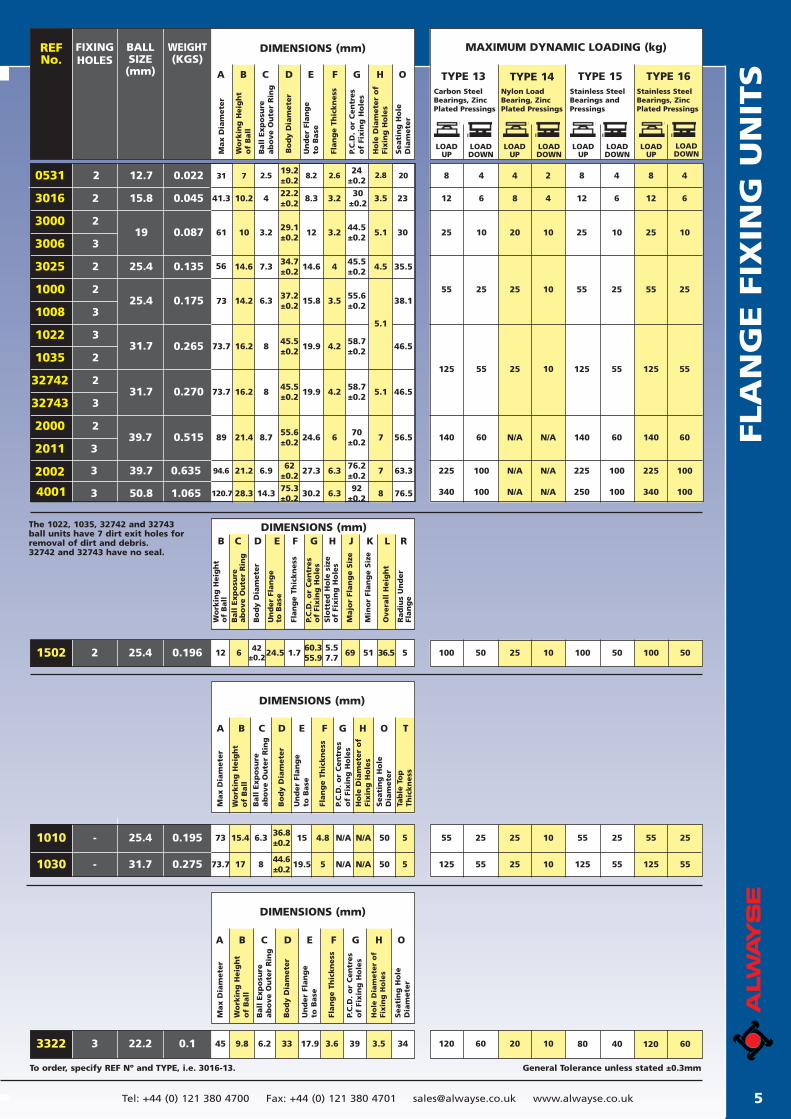
General Tolerance unless stated ±0.3mmTo order, specify REF Nº and TYPE, i.e. 3016-13.
BALLSIZE
(mm)
FIXING HOLES
WEIGHT(KGS)
REF No.
DIMENSIONS (mm) MAXIMUM DYNAMIC LOADING (kg)
3016
3000
3006
3025
1000
1008
1022
1035
2000
2011
2002
2
2
3
2
2
3
3
2
2
32742
32743 3
2
3
3
15.8
25.4
25.4
31.7
39.7
39.7
0.135
0.175
0.265
0.515
0.635
19
0.045
0.087
41.3 10.2 4
61 10 3.2
14.656 7.3
14.273 6.3
73.7 16.2 8
89 21.4 8.7
94.6 21.2 6.9
22.2±0.2
8.3 3.2
29.1±0.2
12 3.2
34.7±0.2
14.6 4
37.2±0.2
15.8 3.5
45.5±0.2
19.9 4.2
55.6±0.2
24.6 6
62±0.2
27.3 6.3
5.1
30±0.2
3.5 23
44.5±0.2
5.1 30
45.5±0.2
4.5 35.5
55.6±0.2
38.1
58.7±0.2
46.5
70±0.2
56.57
31.7 0.270 73.7 16.2 845.5±0.2
19.9 4.258.7±0.2
46.55.1
76.2±0.2
63.37
12
4 8 42
8
8 4
25 10 25 101020 25 10
55 25 55 251025 55 25
125 55 125 551025 125 55
140 60 140 60N/AN/A 140 60
225 100 225 100N/AN/A 225 100
LOADUP
LOADDOWN
LOADUP
LOADDOWN
LOADUP
LOADDOWN
LOADUP
LOADDOWN
TYPE 13 TYPE 15Carbon SteelBearings, ZincPlated Pressings
Stainless SteelBearings andPressings
TYPE 14Nylon LoadBearing, ZincPlated Pressings
TYPE 16Stainless SteelBearings, ZincPlated Pressings
Max D
iam
ete
r
Un
der
Flan
ge
to B
ase
P.C
.D.
or
Cen
tres
of
Fixin
g H
ole
s
Seati
ng
Ho
leD
iam
ete
r
Wo
rkin
g H
eig
ht
of
Ball
Ball
Exp
osu
re
ab
ove O
ute
r R
ing
Bo
dy D
iam
ete
r
Flan
ge T
hic
kn
ess
Ho
le D
iam
ete
r o
fFi
xin
g H
ole
s
A B C D E F G H O
DIMENSIONS (mm)
Wo
rkin
g H
eig
ht
of
Ball
Ball
Exp
osu
reab
ove O
ute
r R
ing
Flan
ge T
hic
kn
ess
Slo
tted
Ho
le s
ize
of
Fixin
g H
ole
s
Min
or
Flan
ge S
ize
Bo
dy D
iam
ete
r
Un
der
Flan
ge
to B
ase
P.C
.D.
or
Cen
tres
of
Fixin
g H
ole
s
Majo
r Fl
an
ge S
ize
Overa
ll H
eig
ht
Rad
ius
Un
der
Flan
ge
B C D E F G H J K L R
1502 0.19625.4 100 50 100 501025 100 502 12 6 42±0.224.5 1.7
60.355.9
5.57.7
5169 36.5 5
DIMENSIONS (mm)
Max D
iam
ete
r
Ball
Exp
osu
re
ab
ove O
ute
r R
ing
Un
der
Flan
ge
to B
ase
P.C
.D.
or
Cen
tres
of
Fixin
g H
ole
s
Seati
ng
Ho
leD
iam
ete
r
Wo
rkin
g H
eig
ht
of
Ball
Bo
dy D
iam
ete
r
Flan
ge T
hic
kn
ess
Ho
le D
iam
ete
r o
fFi
xin
g H
ole
s
Tab
le T
op
Th
ickn
ess
A B C D E F G H O T
1010 -
1030 -
25.4
31.7
0.195
0.275
73 15.4 6.336.8±0.2
15 4.8
73.7 17 844.6±0.2
19.5 5
55 25 55 251025 55 25
125 55 125 551025 125 55
N/A 50N/A 5
N/A 50N/A 5
DIMENSIONS (mm)
Max D
iam
ete
r
Ball
Exp
osu
re
ab
ove O
ute
r R
ing
Un
der
Flan
ge
to B
ase
P.C
.D.
or
Cen
tres
of
Fixin
g H
ole
s
Seati
ng
Ho
leD
iam
ete
r
3 22.2 0.1 120 60 80 401020 120 60
Wo
rkin
g H
eig
ht
of
Ball
Bo
dy D
iam
ete
r
Flan
ge T
hic
kn
ess
Ho
le D
iam
ete
r o
fFi
xin
g H
ole
s
3322
A B C D E F G H O
45 9.8 6.2 33 17.9 3.6 39 343.5
The 1022, 1035, 32742 and 32743ball units have 7 dirt exit holes forremoval of dirt and debris.32742 and 32743 have no seal.
0531 2 12.7 0.022 31 7 2.5 8.2 2.6 2.8 20 8
6
4
4 12 6 12 6
19.2±0.2
24±0.2
4001 3 50.8 1.065 120.7 28.3 14.375.3±0.2
30.2 6.392
±0.276.58 340 100 250 100N/AN/A 340 100
IMPORTANT - IF YOU ARE UNSURE, CONSULT OUR FREE TECHNICAL SERVICE. Tel: +44 (0) 121 380 4700 Fax: +44 (0) 121 380 47016
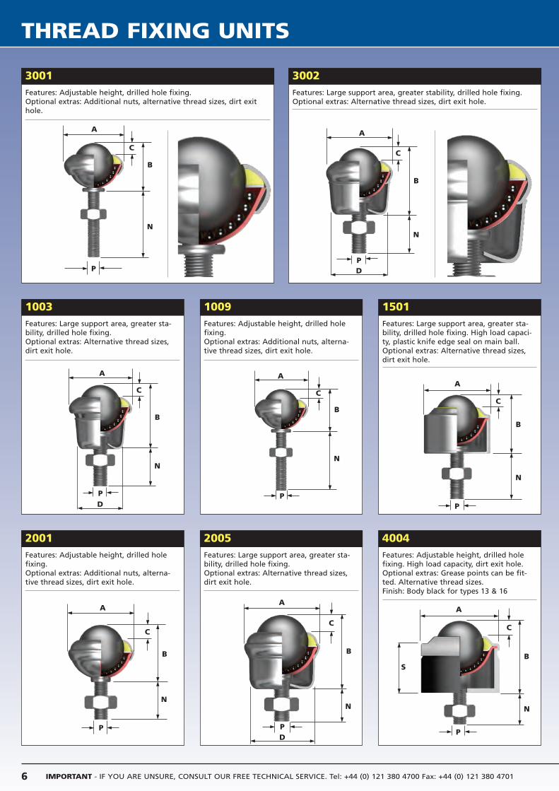
THREAD FIXING UNITS
3001Features: Adjustable height, drilled hole fixing.Optional extras: Additional nuts, alternative thread sizes, dirt exithole.
3002
1003Features: Large support area, greater sta-bility, drilled hole fixing.Optional extras: Alternative thread sizes,dirt exit hole.
1009Features: Adjustable height, drilled holefixing.Optional extras: Additional nuts, alterna-tive thread sizes, dirt exit hole.
2001Features: Adjustable height, drilled holefixing.Optional extras: Additional nuts, alterna-tive thread sizes, dirt exit hole.
2005Features: Large support area, greater sta-bility, drilled hole fixing.Optional extras: Alternative thread sizes,dirt exit hole.
1501Features: Large support area, greater sta-bility, drilled hole fixing. High load capaci-ty, plastic knife edge seal on main ball.Optional extras: Alternative thread sizes,dirt exit hole.
4004
Features: Large support area, greater stability, drilled hole fixing.Optional extras: Alternative thread sizes, dirt exit hole.
Features: Adjustable height, drilled holefixing. High load capacity, dirt exit hole. Optional extras: Grease points can be fit-ted. Alternative thread sizes.Finish: Body black for types 13 & 16
A
C
P
B
N
A
C
PD
B
N
A
C
PD
B
N
A
C
P
B
N
A
C
P
B
N
A
C
P
B
N
S
A
C
P
B
N
A
D
C
P
B
N
TH
REA
D F
IXIN
G U
NIT
S
7Tel: +44 (0) 121 380 4700 Fax: +44 (0) 121 380 4701 [email protected] www.alwayse.co.uk
*Pattern 4004 can be supplied with other screw sizes or plain shanks.
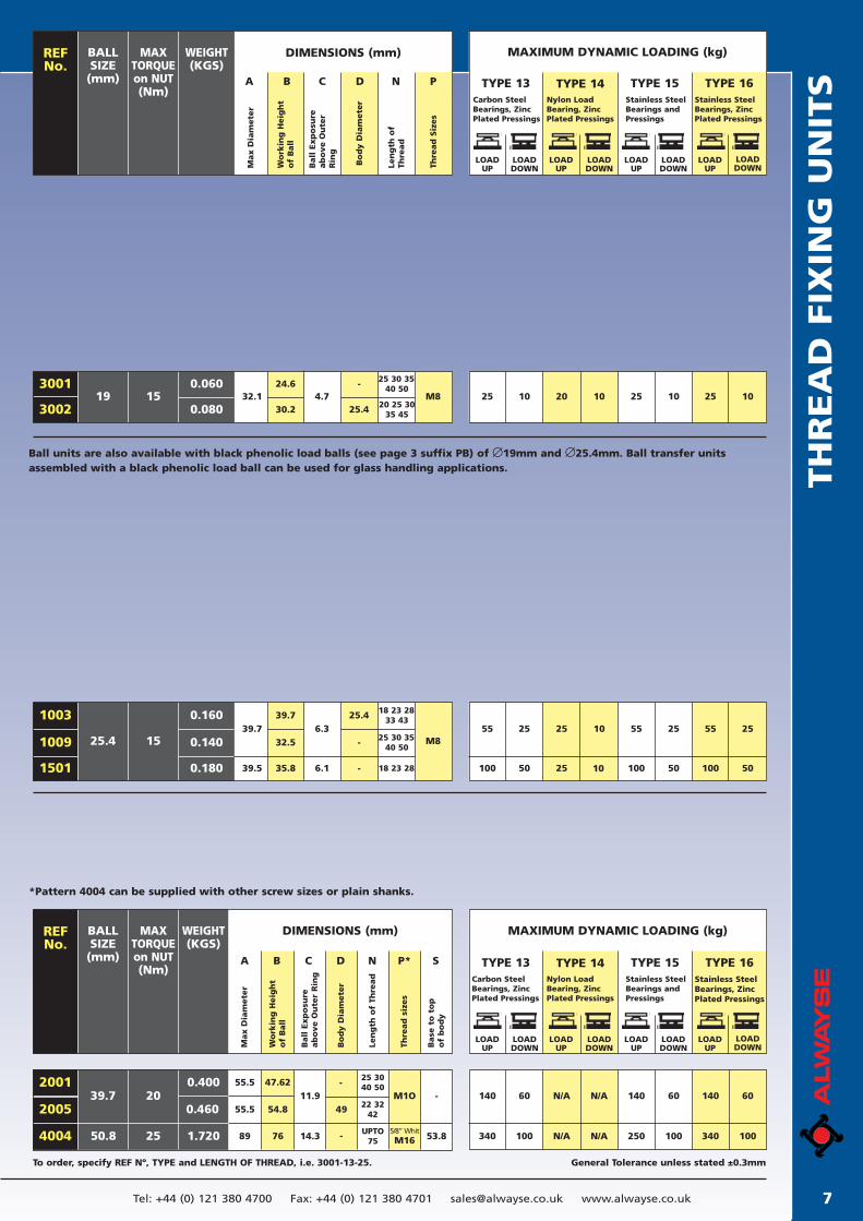
General Tolerance unless stated ±0.3mmTo order, specify REF Nº, TYPE and LENGTH OF THREAD, i.e. 3001-13-25.
MAXTORQUEon NUT(Nm)
BALLSIZE
(mm)
Max D
iam
ete
r
Len
gth
of
Thre
ad
WEIGHT(KGS)
Wo
rkin
g H
eig
ht
of
Ball
Ball
Exp
osu
re
ab
ove O
ute
rR
ing
Bo
dy D
iam
ete
r
Thre
ad
Siz
es
REF No.
DIMENSIONS (mm) MAXIMUM DYNAMIC LOADING (kg)
TYPE 13 TYPE 15A B C D N P TYPE 14 TYPE 16
LOADUP
LOADDOWN
LOADUP
LOADDOWN
Carbon SteelBearings, ZincPlated Pressings
Stainless SteelBearings andPressings
LOADUP
LOADDOWN
Nylon LoadBearing, ZincPlated Pressings
LOADUP
LOADDOWN
Stainless SteelBearings, ZincPlated Pressings
190.060
150.080
32.1 4.7 M824.6 25 30 35
40 50
20 25 3035 4530.2 25.4
-3001
300225 10 25 101020 25 10
25.4 0.140
0.160
15
0.180 39.5
39.7
6.1
6.325.4
M832.5
39.7
25 30 3540 50
18 23 2833 43
18 23 2835.8 -
-
1003
1009
1501
55
100
25
50
25
25
10
10
55
100
25
50
55
100
25
50
DIMENSIONS (mm)MAXTORQUEon NUT(Nm)
BALLSIZE
(mm)
WEIGHT(KGS)
Wo
rkin
g H
eig
ht
of
Ball
Ball
Exp
osu
re
ab
ove O
ute
r R
ing
Len
gth
of
Thre
ad
Thre
ad
siz
es
Base
to
to
po
f b
od
y
Max D
iam
ete
r
Bo
dy D
iam
ete
r
REF No.
A B C D N P* S
MAXIMUM DYNAMIC LOADING (kg)
LOADUP
LOADDOWN
LOADUP
LOADDOWN
TYPE 13 TYPE 15Carbon SteelBearings, ZincPlated Pressings
Stainless SteelBearings andPressings
LOADUP
LOADDOWN
TYPE 14Nylon LoadBearing, ZincPlated Pressings
LOADUP
LOADDOWN
TYPE 16Stainless SteelBearings, ZincPlated Pressings
39.7
50.8
0.460
0.40020
25 1.720 89
55.5
55.5
47.62
14.3
11.954.8
76
2001
2005
4004
49
-5/8” WhitM16 53.8
--M1O 140
340
60
100
N/A
N/A
N/A
N/A
140
250
60
100
140
340
60
100
25 3040 50
22 3242
UPTO75
Ball units are also available with black phenolic load balls (see page 3 suffix PB) of ∅19mm and ∅25.4mm. Ball transfer unitsassembled with a black phenolic load ball can be used for glass handling applications.
IMPORTANT - IF YOU ARE UNSURE, CONSULT OUR FREE TECHNICAL SERVICE. Tel: +44 (0) 121 380 4700 Fax: +44 (0) 121 380 47018
TUBE FIXING • CLAMP FIXING • MISCELLANEOUS UNITS
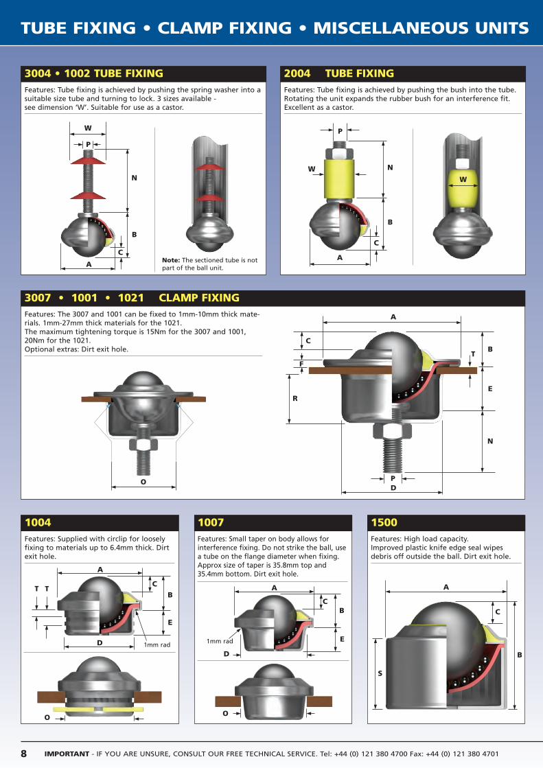
3004 • 1002 TUBE FIXINGFeatures: Tube fixing is achieved by pushing the spring washer into asuitable size tube and turning to lock. 3 sizes available - see dimension ‘W’. Suitable for use as a castor.
2004 TUBE FIXING
3007 • 1001 • 1021 CLAMP FIXINGFeatures: The 3007 and 1001 can be fixed to 1mm-10mm thick mate-rials. 1mm-27mm thick materials for the 1021.The maximum tightening torque is 15Nm for the 3007 and 1001,20Nm for the 1021.Optional extras: Dirt exit hole.
1004Features: Supplied with circlip for looselyfixing to materials up to 6.4mm thick. Dirtexit hole.
1007Features: Small taper on body allows forinterference fixing. Do not strike the ball, use a tube on the flange diameter when fixing. Approx size of taper is 35.8mm top and35.4mm bottom. Dirt exit hole.
1500
Features: Tube fixing is achieved by pushing the bush into the tube.Rotating the unit expands the rubber bush for an interference fit.Excellent as a castor.
Features: High load capacity.Improved plastic knife edge seal wipesdebris off outside the ball. Dirt exit hole.
W
P
N
B
C
A
A
D
R
F
C
P
A
T
D
O
B
E
C
BT
E
N
O
P
WW
N
B
C
A
A
D
O
B
E
C
A
B
S
C
1mm rad1mm rad
Note: The sectioned tube is notpart of the ball unit.
T
TU
BE F
IXIN
G •
CLA
MP F
IXIN
G •
MIS
CELLA
NEO
US U
NIT
S
9Tel: +44 (0) 121 380 4700 Fax: +44 (0) 121 380 4701 [email protected] www.alwayse.co.uk
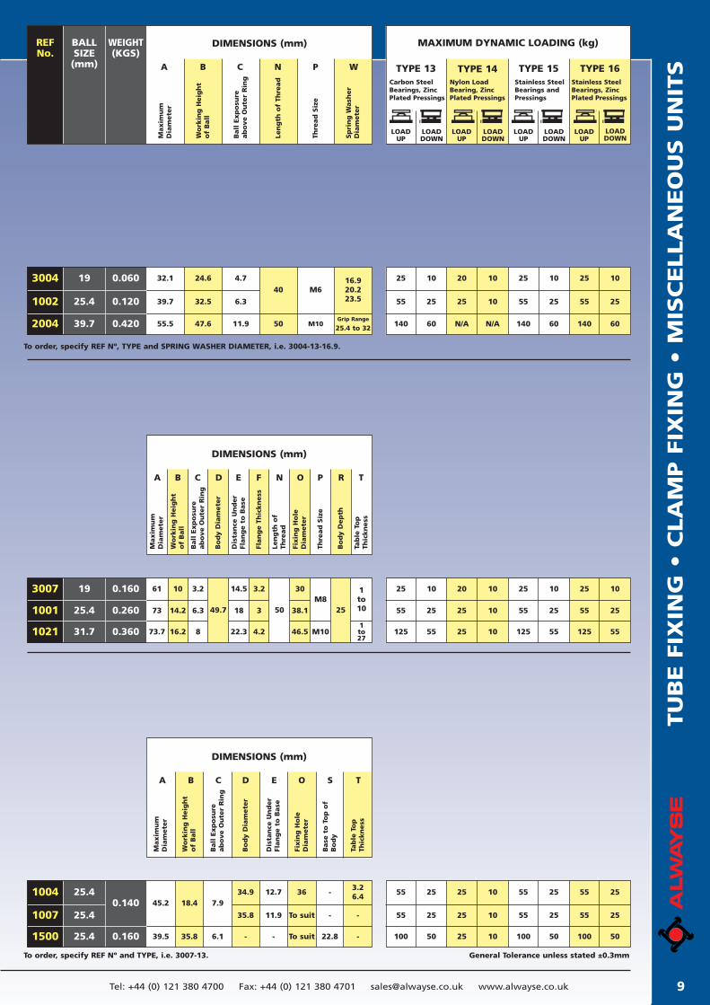
General Tolerance unless stated ±0.3mmTo order, specify REF Nº and TYPE, i.e. 3007-13.
To order, specify REF Nº, TYPE and SPRING WASHER DIAMETER, i.e. 3004-13-16.9.
DIMENSIONS (mm)REF No.
WEIGHT(KGS)
BALLSIZE
(mm)
Maxim
um
Dia
mete
r
Thre
ad
Siz
e
MAXIMUM DYNAMIC LOADING (kg)
LOADUP
LOADDOWN
LOADUP
LOADDOWN
TYPE 13 TYPE 15Carbon SteelBearings, ZincPlated Pressings
Stainless SteelBearings andPressings
Wo
rkin
g H
eig
ht
of
Ball
A B C N P W
Ball
Exp
osu
re
ab
ove O
ute
r R
ing
Len
gth
of
Thre
ad
Sp
rin
g W
ash
er
Dia
mete
r
LOADUP
LOADDOWN
TYPE 14Nylon LoadBearing, ZincPlated Pressings
LOADUP
LOADDOWN
TYPE 16Stainless SteelBearings, ZincPlated Pressings
1002
3004
2004
25.4
19
39.7
0.120
0.060
0.420 140 60 140 60N/AN/A 140 60
55 25 55 251025 55 25
25 10 25 101020 25 1032.1
39.7
55.5
24.6
32.5
47.6
4.7
6.3
11.925.4 to 32Grip Range
16.920.223.5
40
50
M6
M10
1001
3007
1021
25.4
19
31.7
0.260
0.160
0.360
61
73
73.7
14.2
16.2
10
18
22.3 4.2
14.5 3.2
506.3
8
3.2
38.1
M81to10
46.5 M101to27
30
49.7 253
DIMENSIONS (mm)
Maxim
um
Dia
mete
r
Wo
rkin
g H
eig
ht
of
Ball
A B C D E F N O P R T
Ball
Exp
osu
reab
ove O
ute
r R
ing
Bo
dy D
iam
ete
r
Dis
tan
ce U
nd
er
Flan
ge t
o B
ase
Flan
ge T
hic
kn
ess
Bo
dy D
ep
th
Tab
le T
op
Thic
kn
ess
Len
gth
of
Thre
ad
Fixin
g H
ole
Dia
mete
r
Thre
ad
Siz
e
125 55 125 551025 125 55
55 25 55 251025 55 25
25 10 25 101020 25 10
1007
1004
1500
25.4
25.4
25.4
0.140
0.160
45.2
39.5 35.8
18.4
6.1
7.9
35.8
34.9 36
To suit
To suit
-3.26.4
- -
22.8 --
11.9
12.7
-
DIMENSIONS (mm)
Maxim
um
Dia
mete
r
Wo
rkin
g H
eig
ht
of
Ball
A B C D E O S T
Ball
Exp
osu
reab
ove O
ute
r R
ing
Bo
dy D
iam
ete
r
Dis
tan
ce U
nd
er
Flan
ge t
o B
ase
Fixin
g H
ole
Dia
mete
r
Base
to
To
p o
fB
od
y
Tab
le T
op
Thic
kn
ess
100 50 100 501025 100 50
55 25 55 251025 55 25
55 25 55 251025 55 25
IMPORTANT - IF YOU ARE UNSURE, CONSULT OUR FREE TECHNICAL SERVICE. Tel: +44 (0) 121 380 4700 Fax: +44 (0) 121 380 470110
BASE FIXING UNITS
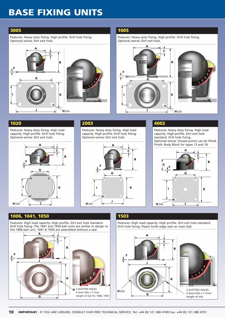
3005Features: Heavy duty fixing. High profile. Drill hole fixing.Optional extras: Dirt exit hole.
1005
1020Features: Heavy duty fixing. High loadcapacity. High profile. Drill hole fixing.Optional extras: Dirt exit hole.
2003Features: Heavy duty fixing. High loadcapacity. High profile. Drill hole fixing.Optional extras: Dirt exit hole.
4002Features: Heavy duty fixing. High loadcapacity. High profile. Dirt exit hole standard. Drill hole fixing. Optional extras: Grease points can be fitted.Finish: Body Black for types 13 and 16.
Features: Heavy duty fixing. High profile. Drill hole fixing.Optional extras: Dirt exit hole.
1006, 1041, 1050Features: High load capacity. High profile. Dirt exit hole standard.Drill hole fixing. The 1041 and 1050 ball units are similar in design tothe 1006 ball unit. 1041 & 1050 are assembled without a seal
1503Features: High load capacity. High profile. Dirt exit hole standard.Drill hole fixing. Plastic knife edge seal on main ball.
A
G
C
B
F
I K
A
C
B
F
J
A
G
C
B
F
I K
J
G
I K
JH DIA
A
C
B
F
J
K
G
2 SLOTTED HOLES 5.5mm DIA x 7.7mm length of slot for 1006, 1050
A
C
B
F
J
K
GH DIA
A
C
B
F
A
C
BS
F
G
I K
JH DIA
H DIA H DIA
G
I K
JH DIA
H 2 SLOTTED HOLES 5.5mm DIA x 7.7mmlength of slot
BA
SE F
IXIN
G U
NIT
S
11Tel: +44 (0) 121 380 4700 Fax: +44 (0) 121 380 4701 [email protected] www.alwayse.co.uk
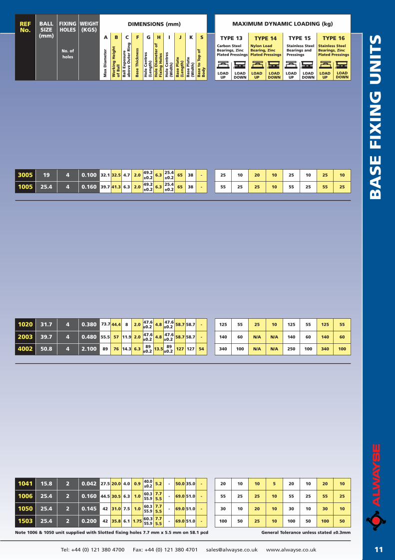
General Tolerance unless stated ±0.3mmNote 1006 & 1050 unit supplied with Slotted fixing holes 7.7 mm x 5.5 mm on 58.1 pcd
DIMENSIONS (mm)FIXINGHOLES
No. ofholes
BALLSIZE
(mm)
Max D
iam
ete
r
WEIGHT(KGS)
Wo
rkin
g H
eig
ht
of
Ball
A B C F G H I J K S
Ball
Exp
osu
reab
ove O
ute
r R
ing
Base
Th
ickn
ess
Ho
le C
en
tres
(Len
gth
)
Ho
le D
iam
ete
r o
fFi
xin
g H
ole
s
Base
Pla
te(W
idth
)
Base
to
To
p o
fB
od
y
Ho
le C
en
tres
(Wid
th)
Base
Pla
te(L
en
gth
)
REF No.
LOADUP
LOADDOWN
LOADUP
LOADDOWN
TYPE 13
LOADUP
LOADDOWN
LOADUP
LOADDOWN
Carbon SteelBearings, ZincPlated Pressings
Stainless SteelBearings andPressings
Nylon LoadBearing, ZincPlated Pressings
Stainless SteelBearings, ZincPlated Pressings
MAXIMUM DYNAMIC LOADING (kg)
19
25.4
25 10 25 101020 25 10
55 25 55 251025 55 25
0.1004
4 0.160
32.5
41.3
32.1
39.7
49.2±0.2
25.4±0.2
65 38 -4.7 2.0
6.3 2.049.2±0.2
6.3
6.325.4±0.2
65 38 -
3005
1005
TYPE 15TYPE 14 TYPE 16
31.7
39.7
0.3804
4 0.480
50.8 4 2.100
44.4
57
2.0 47.6±0.2 4.8 47.6
±0.2 -73.7 8
55.5 11.9 2.0 47.6±0.2 4.8 47.6
±0.2 -
7689 14.3 6.3 89±0.2 13.5 89
±0.2
58.7
58.7
127
58.7
58.7
127 54
1020
2003
4002
125 55 125 551025 125 55
140 60 140 60N/AN/A 140 60
340 100 250 100N/AN/A 340 100
25.4
15.8
25.4
55
20
25
10
55
20
25
10
10
5
25
10
55
20
25
10
30 10 30 101020 30 10
100 50 100 501025 100 50
0.160
0.042
2
2
2 0.145
25.4 2 0.200
30.5
20.0
31.0
1.0
0.9
69.0
50.0
51.0
35.0
60.355.9
40.0±0.2
-
-
44.5
27.5
6.3
4.0
42 7.5 1.0 69.0 51.060.355.9 -
35.842 6.1 1.75
7.75.5
5.2
7.75.5
7.75.5
69.0 51.060.355.9 -
-
-
-
-
1006
1041
1050
1503
IMPORTANT - IF YOU ARE UNSURE, CONSULT OUR FREE TECHNICAL SERVICE. Tel: +44 (0) 121 380 4700 Fax: +44 (0) 121 380 470112
MINI BALL TRANSFER UNITS
A
C
B
L
P
N
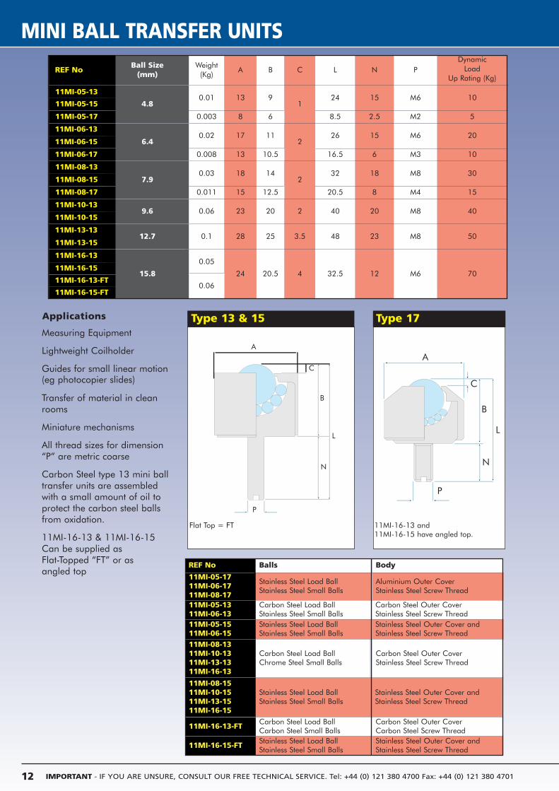
Applications
Measuring Equipment
Lightweight Coilholder
Guides for small linear motion (eg photocopier slides)
Transfer of material in cleanrooms
Miniature mechanisms
All thread sizes for dimension“P” are metric coarse
Carbon Steel type 13 mini balltransfer units are assembledwith a small amount of oil toprotect the carbon steel ballsfrom oxidation.
11MI-16-13 & 11MI-16-15Can be supplied as Flat-Topped “FT” or asangled top
Type 13 & 15 Type 17
Ball Size (mm)
Weight(Kg)
A B C L N PDynamic
Load Up Rating (Kg)
4.80.01 13 9
124 15 M6 10
11MI-05-17
11MI-05-15
0.003 8 6 8.5 2.5 M2 5
6.40.02 17 11
226 15 M6 20
11MI-06-15
11MI-06-17 0.008 13 10.5 16.5 6 M3 10
7.90.03 18 14
232 18 M8 30
11MI-08-15
11MI-08-17 0.011 15 12.5 20.5 8 M4 15
9.6 0.06 23 20 2 40 20 M8 4011MI-10-15
12.7 0.1 28 25 3.5 48 23 M8 5011MI-13-15
15.8
0.05
24 20.5 4 32.5 12 M6 7011MI-16-15
REF No Balls Body
11MI-05-1711MI-06-1711MI-08-17
Stainless Steel Load BallStainless Steel Small Balls
Aluminium Outer CoverStainless Steel Screw Thread
11MI-05-1311MI-06-13
Carbon Steel Load BallStainless Steel Small Balls
Carbon Steel Outer CoverStainless Steel Screw Thread
11MI-05-1511MI-06-15
Stainless Steel Load BallStainless Steel Small Balls
Stainless Steel Outer Cover andStainless Steel Screw Thread
11MI-08-1311MI-10-1311MI-13-1311MI-16-13
Carbon Steel Load BallChrome Steel Small Balls
Carbon Steel Outer CoverStainless Steel Screw Thread
11MI-08-1511MI-10-1511MI-13-1511MI-16-15
Stainless Steel Load BallStainless Steel Small Balls
Stainless Steel Outer Cover andStainless Steel Screw Thread
11MI-16-13 and11MI-16-15 have angled top.
A
C
B
L
P
N
A
C
B
L
P
N
Carbon Steel Outer CoverCarbon Steel Screw Thread
Carbon Steel Load BallCarbon Steel Small Balls
Stainless Steel Outer Cover andStainless Steel Screw Thread
Stainless Steel Load BallStainless Steel Small Balls
11MI-16-13-FT
11MI-16-15-FT
11MI-16-13-FT
11MI-16-15-FT0.06
REF No
11MI-06-13
11MI-05-13
11MI-08-13
11MI-10-13
11MI-13-13
11MI-16-13
Flat Top = FT
GLA
SS H
AN
DLI
NG
/ F
LAT
SH
EET
MA
TER
IAL
F
LOA
T-O
N
13Tel: +44 (0) 121 380 4700 Fax: +44 (0) 121 380 4701 [email protected] www.alwayse.co.uk
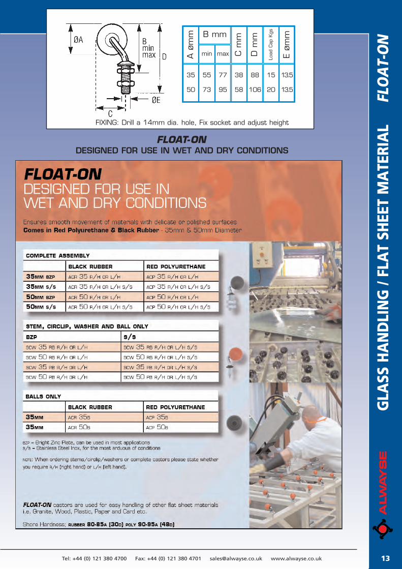
35
50
55
73
77
95
38
58
88
106
15
20
13.5
13.5
A ø
mm
C m
m
D m
m
E øm
m
Load
Cap
KgsB mm
min max
FIXING: Drill a 14mm dia. hole, Fix socket and adjust height
FLOAT-ON DESIGNED FOR USE IN WET AND DRY CONDITIONS
IMPORTANT - IF YOU ARE UNSURE, CONSULT OUR FREE TECHNICAL SERVICE. Tel: +44 (0) 121 380 4700 Fax: +44 (0) 121 380 470114
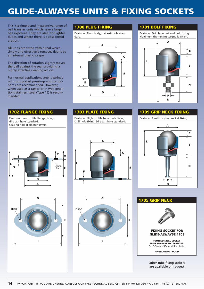
GLIDE-ALWAYSE UNITS & FIXING SOCKETS
This is a simple and inexpensive range ofball transfer units which have a largeball exposure. They are ideal for lighterduties and where there is a cost consid-eration.
All units are fitted with a seal whichsimply and effectively removes debris byan internal plastic scraper.
The direction of rotation slightly movesthe ball against the seal providing ahighly effective cleaning action.
For normal applications steel bearingswith zinc plated pressings and compo-nents are recommended. However,when used as a castor or in wet condi-tions stainless steel (Type 15) is recom-mended.
1702 FLANGE FIXING 1703 PLATE FIXING
1700 PLUG FIXING 1701 BOLT FIXING
1709 GRIP NECK FIXING
Features: Plain body, dirt exit hole stan-dard.
Features: Drill hole nut and bolt fixing.Maximum tightening torque is 15Nm.
Features: Low profile flange fixing,dirt exit hole standard.Seating hole diameter 39mm.
Features: Plastic or steel socket fixing.Features: High profile base plate fixing.Drill hole fixing. Dirt exit hole standard.
A
C
D
L
E
S
A
C
D
L
P
S
N
A
C
D
L
P
S
N
G
K
J
H DIA
G
K
J
H DIA
L
S
C
F
A
3mm Rad
D
L
ES
C B
F
A
FIXING SOCKET FOR GLIDE-ALWAYSE 1709
TOOTHED STEEL SOCKET WITH 19mm HEAD DIAMETER
For 9.5mm x 35mm drilled hole.
APPLICATION: WOOD
1705 GRIP NECK
Other tube fixing sockets are available on request
SPEC
IAL B
ALL U
NIT
S
&
FIX
ING
SO
CK
ETS
15Tel: +44 (0) 121 380 4700 Fax: +44 (0) 121 380 4701 [email protected] www.alwayse.co.uk
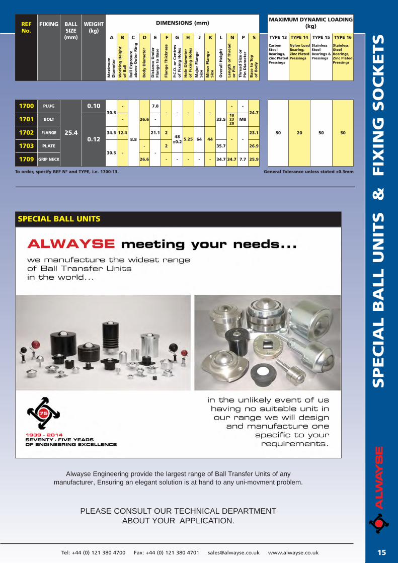
General Tolerance unless stated ±0.3mmTo order, specify REF Nº and TYPE, i.e. 1700-13.
DIMENSIONS (mm)REFNo.
BALL SIZE(mm)
WEIGHT(kg)
FIXING
A B C D E F G H J K L N P S
Maxim
um
Dia
mete
r
Wo
rkin
g H
eig
ht
of
Ball
Ball
Exp
osu
reab
ove O
ute
r R
ing
Bo
dy D
iam
ete
r
Dis
tan
ce U
nd
er
Flan
ge t
o B
ase
Flan
ge T
hic
kn
ess
P.C
.D.
or
Cen
tres
of
Fixin
g H
ole
s
Ho
le D
iam
ete
ro
f Fi
xin
g H
ole
s
Majo
r Fl
an
ge
Siz
e
Min
or
Flan
ge
Siz
e
Overa
ll H
eig
ht
Len
gth
of
Thre
ad
or
Pin
Thre
ad
Siz
e o
rPin
Dia
mete
r
Base
to
To
po
f B
od
y
TYPE 13
Carbon Steel Bearings, Zinc Plated Pressings
TYPE 15
StainlessSteel Bearings & Pressings
TYPE 16
StainlessSteel Bearings,Zinc PlatedPressings
TYPE 14
Nylon LoadBearing, Zinc Plated Pressings
1700
1701
1702
1703
1709
PLUG 0.10
BOLT
FLANGE
PLATE
GRIP NECK
2
2
5.2548
±0.2
-
-
64 44
35.7
34.7 34.7 7.7 25.9
- -
33.5 M8
23.1
26.9
182328
-
- -
24.7
- - -
30.5
7.8
-
21.1
-
-
12.4
-
8.8
26.6
-
26.6 -
34.5
30.5
50 20 50 50
- --
MAXIMUM DYNAMIC LOADING(kg)
25.40.12
-
SPECIAL BALL UNITS
Alwayse Engineering provide the largest range of Ball Transfer Units of any manufacturer, Ensuring an elegant solution is at hand to any uni-movment problem.
PLEASE CONSULT OUR TECHNICAL DEPARTMENTABOUT YOUR APPLICATION.
IMPORTANT - IF YOU ARE UNSURE, CONSULT OUR FREE TECHNICAL SERVICE. Tel: +44 (0) 121 380 4700 Fax: +44 (0) 121 380 470116
EURO UNITS
EURO 4Features: Various fixing clips available,coned outer ring. Dimensionally compati-ble with the 800 series, see pages 18 & 19.
EURO 6Features: Various fixing clips available.Reinforced coned outer ring and supportcup for improved protection against shockloading. Dimensionally compatible with the800 series. Woollen felt seals are standardexcept for the 515-6 ball unit.
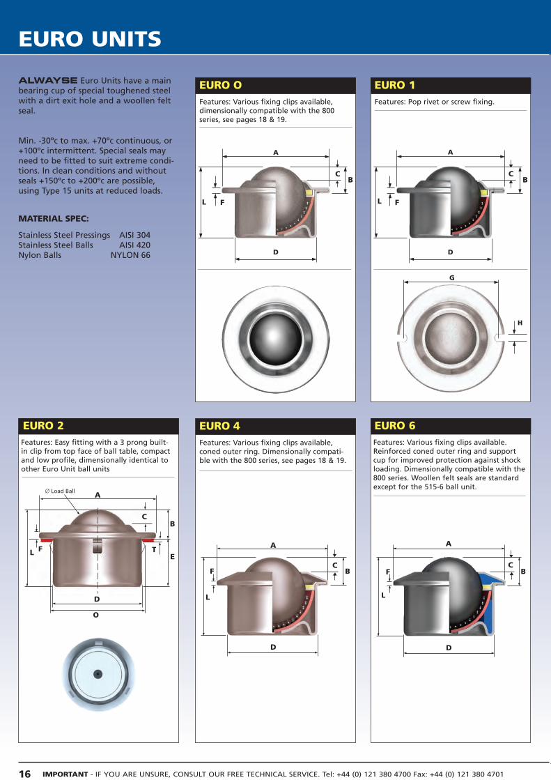
EURO OFeatures: Various fixing clips available,dimensionally compatible with the 800series, see pages 18 & 19.
ALWAYSE Euro Units have a mainbearing cup of special toughened steelwith a dirt exit hole and a woollen feltseal.
Min. -30ºc to max. +70ºc continuous, or+100ºc intermittent. Special seals mayneed to be fitted to suit extreme condi-tions. In clean conditions and withoutseals +150ºc to +200ºc are possible,using Type 15 units at reduced loads.
MATERIAL SPEC:
Stainless Steel Pressings AISI 304Stainless Steel Balls AISI 420Nylon Balls NYLON 66
EURO 1Features: Pop rivet or screw fixing.
A
D
F
B
L
G
H
A
D
F B
L
Features: Easy fitting with a 3 prong built-in clip from top face of ball table, compactand low profile, dimensionally identical toother Euro Unit ball units
A
D
F B
L
A
D
F
B
L
EURO 2
A
D
F
B
L ET
O
∅ Load Ball
C C
C
C
C
EU
RO
UN
ITS
Tel: +44 (0) 121 380 4700 Fax: +44 (0) 121 380 4701 [email protected] www.alwayse.co.uk
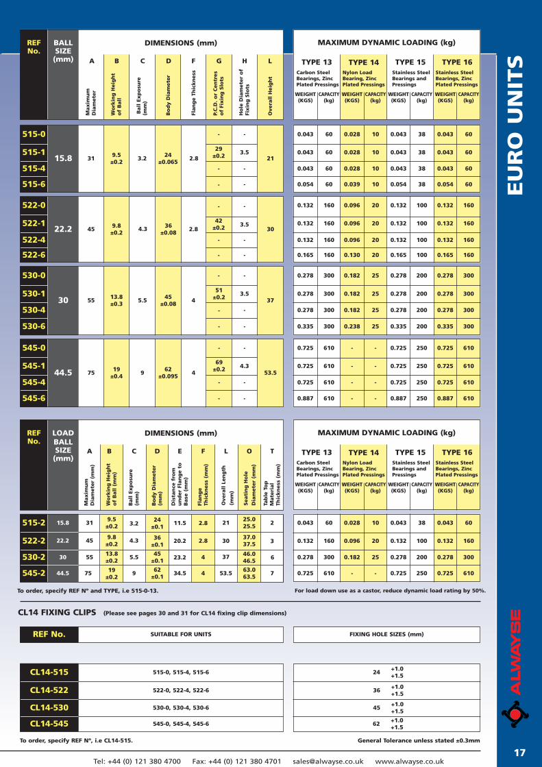
CL14 FIXING CLIPS (Please see pages 30 and 31 for CL14 fixing clip dimensions)
General Tolerance unless stated ±0.3mmTo order, specify REF Nº, i.e CL14-515.
To order, specify REF Nº and TYPE, i.e 515-0-13. For load down use as a castor, reduce dynamic load rating by 50%.
DIMENSIONS (mm)REF No.
BALLSIZE
(mm)
Maxim
um
Dia
mete
r
P.C
.D.
or
Cen
tres
of
Fixin
g S
lots
MAXIMUM DYNAMIC LOADING (kg)
TYPE 13 TYPE 15Carbon SteelBearings, ZincPlated Pressings
Stainless SteelBearings andPressings
Wo
rkin
g H
eig
ht
of
Ball
A B C D F G H L
Bo
dy D
iam
ete
r
Flan
ge T
hic
kn
ess
Overa
ll H
eig
ht
TYPE 14Nylon LoadBearing, ZincPlated Pressings
TYPE 16Stainless SteelBearings, ZincPlated Pressings
Ho
le D
iam
ete
r o
fFi
xin
g S
lots
WEIGHT(KGS)
CAPACITY(kg)
WEIGHT(KGS)
CAPACITY(kg)
WEIGHT(KGS)
CAPACITY(kg)
WEIGHT(KGS)
CAPACITY(kg)
515-1
515-0
515-4
515-6
15.80.043
0.054
0.043
0.054
0.028
0.039
38
38
0.043 0.0430.028 38
0.043
60
60
60
60 0.0430.028
10
10
10
10 38
0.043
0.054
0.043
0.043
60
60
60
60
319.5±0.2
24±0.065
- -
2.8
29±0.2
3.521
-
-
-
-
522-1
522-0
522-4
522-6
22.2 459.8±0.2
36±0.08
- -
2.842
±0.2 3.530
-
-
-
-
0.132
0.165
0.132
0.165
0.096
0.130
100
100
0.132 0.1320.096 100
0.132
160
160
160
160 0.1320.096
20
20
20
20 100
0.132
0.165
0.132
0.132
160
160
160
160
530-1
530-0
530-4
530-6
30 5513.8±0.3
45±0.08
- -
4
51±0.2
3.537
- -
- -
0.278
0.335
0.278
0.335
0.182
0.238
200
200
0.278 0.2780.182 200
0.278
300
300
300
300 0.2780.182
25
25
25
25 200
0.278
0.335
0.278
0.278
300
300
300
300
545-1
545-0
545-4
545-6
44.5 7519
±0.462
±0.095
- -
4
69±0.2 4.3
53.5
- -
- -
0.725
0.887
0.725
0.887
-
-
250
250
0.725 0.725- 250
0.725
610
610
610
610 0.725-
-
-
-
- 250
0.725
0.887
0.725
0.725
610
610
610
610
CL14-522
CL14-515
CL14-530
CL14-545
45
62+1.0+1.5
36
24
+1.0+1.5
+1.0+1.5
+1.0+1.5
515-0, 515-4, 515-6
522-0, 522-4, 522-6
530-0, 530-4, 530-6
545-0, 545-4, 545-6
REF No. SUITABLE FOR UNITS FIXING HOLE SIZES (mm)
DIMENSIONS (mm)REF No.
LOADBALLSIZE
(mm)A B C D E F L O T
MAXIMUM DYNAMIC LOADING (kg)
TYPE 13 TYPE 15Carbon SteelBearings, ZincPlated Pressings
Stainless SteelBearings andPressings
TYPE 14Nylon LoadBearing, ZincPlated Pressings
TYPE 16Stainless SteelBearings, ZincPlated Pressings
WEIGHT(KGS)
CAPACITY(kg)
WEIGHT(KGS)
CAPACITY(kg)
WEIGHT(KGS)
CAPACITY(kg)
WEIGHT(KGS)
CAPACITY(kg)
522-2
515-2
530-2
545-2
-
-
-
0.278
0.725
0.278
0.725
0.182
-
200
250
0.132 0.1320.096 100
0.043
300
610
160
60 0.0430.028
25
-
20
10 38
0.278
0.725
0.132
0.043
300
610
160
60
Maxim
um
Dia
mete
r (m
m)
Wo
rkin
g H
eig
ht
of
Ball
(m
m)
Ball
Exp
osu
re(m
m)
Bo
dy D
iam
ete
r(m
m)
Dis
tan
ce f
rom
un
der
Flan
ge t
oB
ase
(m
m)
Flan
ge
Thic
kn
ess
(m
m)
Overa
ll L
en
gth
(mm
)
Seati
ng
Ho
le
Dia
mete
r (m
m)
Tab
le T
op
Mate
rial
Thic
kn
ess
(m
m)
24±0.1
36±0.1
45±0.1
62±0.1
3.2
4.3
5.5
9
9.5±0.2
9.8±0.2
13.8±0.2
19±0.2
31
45
55
75
2.8
2.8
4
4
21
30
37
53.5
25.025.5
37.037.5
46.046.5
63.063.5
2
3
6
7
11.5
20.2
23.2
34.5
15.8
22.2
30
44.5
Ball
Exp
osu
re
(mm
)
3.2
4.3
5.5
9
17
IMPORTANT - IF YOU ARE UNSURE, CONSULT OUR FREE TECHNICAL SERVICE. Tel: +44 (0) 121 380 4700 Fax: +44 (0) 121 380 470118
HEAVY-DUTY UNITS, SERIES 800
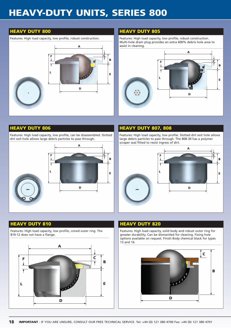
HEAVY DUTY 800 HEAVY DUTY 805Features: High load capacity, low profile, robust construction. Features: High load capacity, low profile, robust construction.
Multi-hole drain plug provides an extra 600% debris hole area toassist in cleaning.
D
LE
CB
F
A
D
LE
CB
A
HEAVY DUTY 810Features: High load capacity, low profile, coned outer ring. The810-12 does not have a flange.
HEAVY DUTY 820Features: High load capacity, solid body and robust outer ring forgreater durability. Can be dismantled for cleaning. Fixing holeoptions available on request. Finish Body chemical black for types13 and 16.
D
L E
CB
A
D
C
B
F
HEAVY DUTY 806 HEAVY DUTY 807, 808Features: High load capacity, low profile, can be disassembled. Slotteddirt exit hole allows large debris particles to pass through.
Features: High load capacity, low profile. Slotted dirt exit hole allowslarge debris particles to pass through. The 808-30 has a polymerscraper seal fitted to resist ingress of dirt.
D
LE
CB
F
A
F
D
LE
CB
F
A
19
HEA
VY-D
UTY
UN
ITS,
SER
IES 8
00
19Tel: +44 (0) 121 380 4700 Fax: +44 (0) 121 380 4701 [email protected] www.alwayse.co.uk
*Please consult us when mounting in inverted position as a castor, load down.
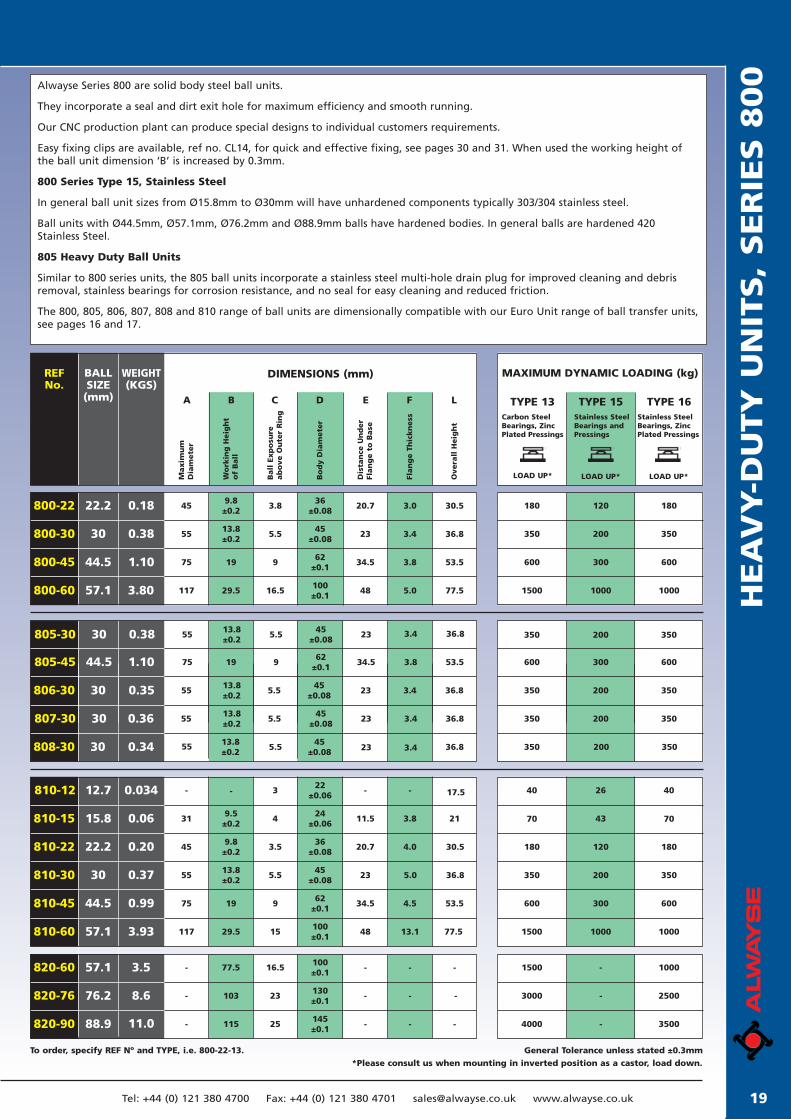
General Tolerance unless stated ±0.3mmTo order, specify REF Nº and TYPE, i.e. 800-22-13.
DIMENSIONS (mm)REF No.
WEIGHT(KGS)
BALLSIZE
(mm)
Maxim
um
Dia
mete
r
Dis
tan
ce U
nd
er
Flan
ge t
o B
ase
MAXIMUM DYNAMIC LOADING (kg)
LOAD UP*
TYPE 15Stainless SteelBearings andPressings
Wo
rkin
g H
eig
ht
of
Ball
A B C D E F L
Ball
Exp
osu
re
ab
ove O
ute
r R
ing
Bo
dy D
iam
ete
r
Flan
ge T
hic
kn
ess
Overa
ll H
eig
ht
LOAD UP*
Carbon SteelBearings, ZincPlated Pressings
LOAD UP*
TYPE 16Stainless SteelBearings, ZincPlated Pressings
TYPE 13
800-22
800-30
800-45
800-60
45
55
75
117
9.8±0.2
13.8±0.2
19
29.5
3.8
5.5
9
16.5
36±0.08
45±0.08
62±0.1
100±0.1
20.7
23
34.5
48
3.0
3.4
3.8
5.0
30.5
36.8
53.5
77.5
22.2
30
44.5
57.1
0.18
0.38
1.10
3.80
180
350
600
1500
180
350
600
1000
120
200
300
1000
810-15
810-22
810-30
810-45
31
45
55
75
9.5±0.2
9.8±0.2
13.8±0.2
19
4
3.5
5.5
9
24±0.06
36±0.08
45±0.08
62±0.1
11.5
20.7
23
34.5
3.8
4.0
5.0
4.5
21
30.5
36.8
53.5
70
180
350
600
70
180
350
600
43
120
200
300
15.8
22.2
30
44.5
0.06
0.20
0.37
0.99
820-60
820-76
820-90
-
-
-
77.5
103
115
16.5
23
25
100±0.1
130±0.1
145±0.1
-
-
-
-
-
-
-
-
-
1500
3000
4000
1000
2500
3500
-
-
-
57.1
76.2
88.9
3.5
8.6
11.0
805-30
805-45
55
75
13.8±0.2
5.5
9
45±0.08
62±0.1
23
34.5
3.4
3.8
36.8
53.5
350
600
350
600
200
300
30
44.5
0.38
1.10
806-30
807-30
55
55
13.8±0.2
13.8±0.2
5.5
5.5
45±0.08
45±0.08
23
23
3.4
3.4
36.8
36.8
350
350
350
350
200
200
30
30
0.35
0.36
Alwayse Series 800 are solid body steel ball units.
They incorporate a seal and dirt exit hole for maximum efficiency and smooth running.
Our CNC production plant can produce special designs to individual customers requirements.
Easy fixing clips are available, ref no. CL14, for quick and effective fixing, see pages 30 and 31. When used the working height ofthe ball unit dimension ‘B’ is increased by 0.3mm.
800 Series Type 15, Stainless Steel
In general ball unit sizes from Ø15.8mm to Ø30mm will have unhardened components typically 303/304 stainless steel.
Ball units with Ø44.5mm, Ø57.1mm, Ø76.2mm and Ø88.9mm balls have hardened bodies. In general balls are hardened 420Stainless Steel.
805 Heavy Duty Ball Units
Similar to 800 series units, the 805 ball units incorporate a stainless steel multi-hole drain plug for improved cleaning and debrisremoval, stainless bearings for corrosion resistance, and no seal for easy cleaning and reduced friction.
The 800, 805, 806, 807, 808 and 810 range of ball units are dimensionally compatible with our Euro Unit range of ball transfer units,see pages 16 and 17.
0.34808-30 30 55 13.8±0.2
19
5.5
45±0.08 23 3.4 36.8 350 350200
810-12 - 17.5322
±0.06- --12.7 0.034
810-60 117 29.5 15100±0.1
48 13.1 77.557.1 3.93
40 4026
1500 10001000
IMPORTANT - IF YOU ARE UNSURE, CONSULT OUR FREE TECHNICAL SERVICE. Tel: +44 (0) 121 380 4700 Fax: +44 (0) 121 380 470120
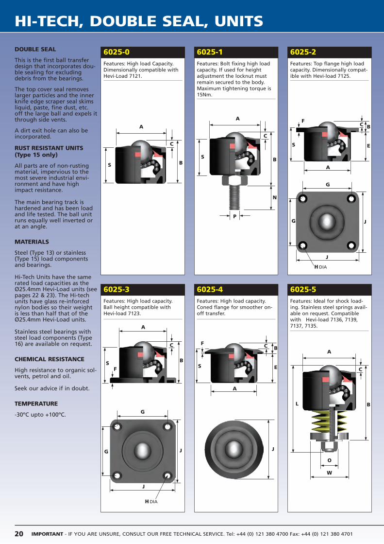
HI-TECH, DOUBLE SEAL, UNITS
6025-2Features: Top flange high loadcapacity. Dimensionally compat-ible with Hevi-load 7125.
6025-1Features: Bolt fixing high loadcapacity. If used for heightadjustment the locknut mustremain secured to the body.Maximum tightening torque is15Nm.
6025-0Features: High load Capacity.Dimensionally compatible withHevi-Load 7121.
6025-5Features: Ideal for shock load-ing. Stainless steel springs avail-able on request. Compatiblewith Hevi-load 7136, 7139,7137, 7135.
6025-4Features: High load capacity.Coned flange for smoother on-off transfer.
6025-3Features: High load capacity.Ball height compatible with Hevi-load 7123.
DOUBLE SEAL
This is the first ball transferdesign that incorporates dou-ble sealing for excludingdebris from the bearings.
The top cover seal removeslarger particles and the innerknife edge scraper seal skimsliquid, paste, fine dust, etc.off the large ball and expels itthrough side vents.
A dirt exit hole can also beincorporated.
RUST RESISTANT UNITS(Type 15 only)
All parts are of non-rustingmaterial, impervious to themost severe industrial envi-ronment and have highimpact resistance.
The main bearing track ishardened and has been loadand life tested. The ball unitruns equally well inverted orat an angle.
MATERIALS
Steel (Type 13) or stainless(Type 15) load componentsand bearings.
Hi-Tech Units have the samerated load capacities as theØ25.4mm Hevi-Load units (seepages 22 & 23). The Hi-techunits have glass re-inforcednylon bodies so their weightis less than half that of theØ25.4mm Hevi-Load units.
Stainless steel bearings withsteel load components (Type16) are available on request.
CHEMICAL RESISTANCE
High resistance to organic sol-vents, petrol and oil.
Seek our advice if in doubt.
TEMPERATURE
-30ºC upto +100ºC.
A
B
C
S
A
B
C
SF
A
E
C BF
S
A
B
N
P
C
S
A
E
C BF
S
A
B
C
L
O
W
G J
G
J
J
G
G
J
J
H DIA
H DIA
HI-
TEC
H,
DO
UB
LE S
EA
L,
UN
ITS
21Tel: +44 (0) 121 380 4700 Fax: +44 (0) 121 380 4701 [email protected] www.alwayse.co.uk
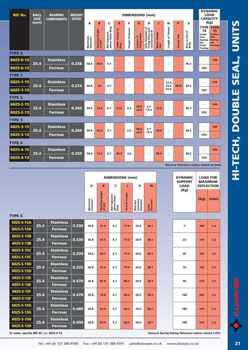
General Spring Rating Tolerance unless stated ±10%To order, specify REF Nº, i.e. 6025-0-15.
DIMENSIONS (mm)REF No. BEARINGCOMPONENTS
BALLSIZE
(mm)
Maxim
um
Dia
mete
r
DYNAMICLOAD
CAPACITY(kg)
Wo
rkin
g H
eig
ht
of
Ball
A B C E F G H J N P S
Ball
Exp
osu
re
ab
ove O
ute
r R
ing
Un
der
Flan
ge t
oB
ase
Flan
ge T
hic
kn
ess
Cen
tres
of
Fixin
g H
ole
s
Ho
le D
iam
ete
r o
fFi
xin
g H
ole
s an
dco
un
ters
un
k Ø
Majo
r Fl
an
ge
Siz
e
Len
gth
of
Thre
ad
Thre
ad
Siz
e
Base
to
To
p o
fB
od
y
TYPE13
TYPE15
WEIGHT(KGS)
Carbon Steel Bearings, Zinc PlatedPressings
Stainless Steel Bearings and Pressings
6025-0-13
6025-0-15
TYPE 0
25.4 0.238Ferrous
Stainless50.8 45.0 - - - - - - - 38.36.7
- 240
320 -
- 240
320 -6025-1-13
6025-1-15
TYPE 1
25.4 0.274Ferrous
Stainless50.8 53 - - - - -
17.632.642.6
M10 38.36.7
- 240
320 -6025-2-13
6025-2-15
TYPE 2
25.4 0.260Ferrous
Stainless50.8 13.0 32.0 6.3
58.0±0.2
6.713.2
76.0 - - 38.36.7
6025-3-13
6025-3-15
TYPE 3
25.4 0.260Ferrous
Stainless50.8 45.0 - 6.3
58.0±0.2
6.713.2
76.0 - - 38.36.7- 240
320 -
- 240
320 -6025-4-13
6025-4-15
TYPE 4
25.4 0.250Ferrous
Stainless50.8 13.0 32.0 3.0 - - 68.6 - - 38.36.7
Maxim
um
Dia
mete
r
A B C L O W
Wo
rkin
g H
eig
ht
of
Ball
Ball
Exp
osu
reA
bo
ve O
ute
rR
ing
Overa
ll L
en
gth
M10 N
ut
Cle
ara
nce
Dia
mete
r
Co
llar
Dia
mete
r
DIMENSIONS (mm) DYNAMICSUPPORT
LOAD(Kg)
LOAD FORMAXIMUM
DEFLECTION
General Tolerance unless stated ±0.3mm
(Kg) (mm)
6025-5-13A
6025-5-15B
6025-5-13B
6025-5-15C
6025-5-13C
6025-5-15D
6025-5-13D
6025-5-15E
6025-5-13E
6025-5-15F
6025-5-13F
6025-5-15G
6025-5-13G
6025-5-15H
6025-5-13H
6025-5-15A
TYPE 5
25.4
25.4
25.4
25.4
25.4
25.4
25.4
25.4
Ferrous
Ferrous
Stainless
Stainless
Ferrous
Stainless
Ferrous
Stainless
Ferrous
Stainless
Ferrous
Stainless
Ferrous
Stainless
Ferrous
Stainless
0.330
0.330
0.330
0.335
0.470
0.470
0.480
0.490
50.8 61.9 6.7 77.0 20.0 38.1
50.8 61.5 6.7 77.0 20.0 38.1
50.8 60.7 6.7 77.0 20.0 38.1
50.8 61.9 6.7 77.0 20.0 38.1
50.8 81.0 6.7 98.4 20.0 38.1
50.8 79.8 6.7 98.4 20.0 38.1
50.8 81.0 6.7 98.4 20.0 38.1
50.8 81.0 6.7 98.4 20.0 38.1
7
23
45
70
90
140
180
230
100
110
120
125
210
245
270
310
3.2
3.2
3.2
3.2
3.2
3.2
3.2
3.2
IMPORTANT - IF YOU ARE UNSURE, CONSULT OUR FREE TECHNICAL SERVICE. Tel: +44 (0) 121 380 4700 Fax: +44 (0) 121 380 470122
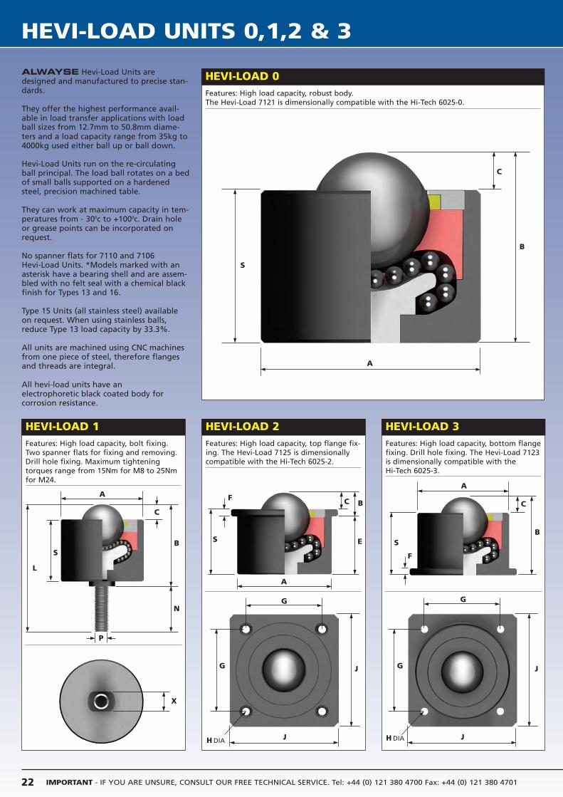
HEVI-LOAD UNITS 0,1,2 & 3
HEVI-LOAD 2Features: High load capacity, top flange fix-ing. The Hevi-Load 7125 is dimensionallycompatible with the Hi-Tech 6025-2.
HEVI-LOAD 3Features: High load capacity, bottom flangefixing. Drill hole fixing. The Hevi-Load 7123is dimensionally compatible with the Hi-Tech 6025-3.
HEVI-LOAD 0Features: High load capacity, robust body.The Hevi-Load 7121 is dimensionally compatible with the Hi-Tech 6025-0.
ALWAYSE Hevi-Load Units aredesigned and manufactured to precise stan-dards.
They offer the highest performance avail-able in load transfer applications with load ball sizes from 12.7mm to 50.8mm diame-ters and a load capacity range from 35kg to 4000kg used either ball up or ball down.
Hevi-Load Units run on the re-circulatingball principal. The load ball rotates on a bedof small balls supported on a hardenedsteel, precision machined table.
They can work at maximum capacity in tem-peratures from - 300c to +1000c. Drain holeor grease points can be incorporated onrequest.
No spanner flats for 7110 and 7106 Hevi-Load Units. *Models marked with anasterisk have a bearing shell and are assem-bled with no felt seal with a chemical blackfinish for Types 13 and 16.
Type 15 Units (all stainless steel) availableon request. When using stainless balls,reduce Type 13 load capacity by 33.3%.
All units are machined using CNC machinesfrom one piece of steel, therefore flangesand threads are integral.
All hevi-load units have an electrophoretic black coated body for corrosion resistance.
HEVI-LOAD 1Features: High load capacity, bolt fixing.Two spanner flats for fixing and removing.Drill hole fixing. Maximum tighteningtorques range from 15Nm for M8 to 25Nmfor M24.
A
C
B
S
A
C
B
P
S
L
X
G
G
J
JG
G
J
J
A
C B
S
F
E
A
C
BS
F
H DIAH DIA
N
HEV
I-LO
AD
UN
ITS 0
,1,2
& 3
23Tel: +44 (0) 121 380 4700 Fax: +44 (0) 121 380 4701 [email protected] www.alwayse.co.uk
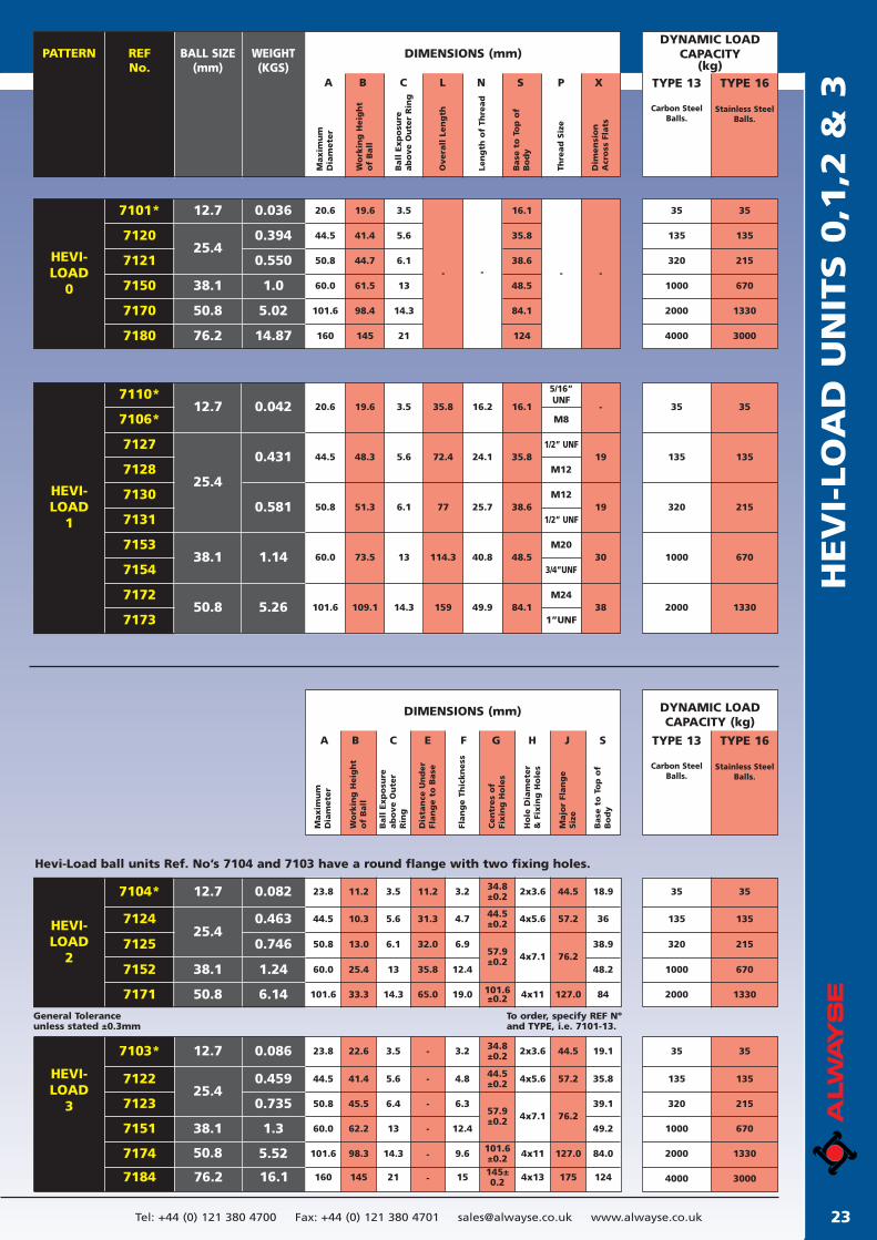
General Toleranceunless stated ±0.3mm
To order, specify REF Nºand TYPE, i.e. 7101-13.
DIMENSIONS (mm)PATTERN BALL SIZE(mm)
WEIGHT(KGS)
REFNo.
Maxim
um
Dia
mete
r
Base
to
To
p o
fB
od
y
Thre
ad
Siz
e
A B C L N S P X
Wo
rkin
g H
eig
ht
of
Ball
Ball
Exp
osu
reab
ove O
ute
r R
ing
Dim
en
sio
nA
cro
ss F
lats
Overa
ll L
en
gth
Len
gth
of
Thre
ad
DYNAMIC LOADCAPACITY
(kg)TYPE 13 TYPE 16
Carbon SteelBalls.
Stainless SteelBalls.
7101*
7120
7121
7150
7170
0.036
0.394
0.550
1.0
5.02
HEVI-LOAD
0
25.4
12.7
38.1
50.8
35
135
320
1000
2000
35
135
215
670
1330
19.6
41.4
44.7
61.5
98.4
3.5
5.6
6.1
13
14.3
16.1
35.8
38.6
48.5
84.1
- - - -
20.6
44.5
50.8
60.0
101.6
7110*
7106*
7127
7128
7130
7131
7153
7154
7172
7173
HEVI-LOAD
1
25.4
38.1
50.8
12.7 0.042
0.431
0.581
1.14
5.26
35
135
320
1000
2000
35
135
215
670
1330
5/16”UNF
M8
1/2” UNF
M12
M12
1/2” UNF
M20
3/4”UNF
M24
1”UNF
20.6
44.5
60.0
101.6
50.8
19.6
48.3
73.5
109.1
51.3
3.5
5.6
13
14.3
6.1
35.8
72.4
114.3
159
77
16.2
24.1
40.8
49.9
25.7
16.1
35.8
48.5
84.1 38
38.6
-
19
30
19
Maxim
um
Dia
mete
r
A B C E F G H J S
Wo
rkin
g H
eig
ht
of
Ball
Ball
Exp
osu
reab
ove O
ute
rR
ing
Dis
tan
ce U
nd
er
Flan
ge t
o B
ase
Flan
ge T
hic
kn
ess
Cen
tres
of
Fixin
g H
ole
s
Ho
le D
iam
ete
r&
Fix
ing
Ho
les
Majo
r Fl
an
ge
Siz
e
Base
to
To
p o
fB
od
y
DIMENSIONS (mm) DYNAMIC LOADCAPACITY (kg)
TYPE 13 TYPE 16
Carbon SteelBalls.
Stainless SteelBalls.
35
135
320
1000
2000
35
135
215
670
1330
35
135
320
1000
2000
35
135
215
670
1330
7104*
7124
7125
7152
7171
0.082
0.463
0.746
1.24
6.14
HEVI-LOAD
2
25.4
12.7
38.1
50.8
11.2
10.3
13.0
25.4
33.3
23.8
44.5
50.8
60.0
101.6
3.5
5.6
6.1
13
14.3
11.2
31.3
32.0
35.8
65.0
3.2
4.7
6.9
12.4
19.0
34.8±0.2
44.5±0.2
57.9±0.2
101.6±0.2
2x3.6
4x5.6
4x7.1
4x11
44.5
57.2
76.2
127.0
18.9
36
38.9
48.2
84
7103*
7122
7123
7151
7174
HEVI-LOAD
325.4
12.7
38.1
50.8
22.6
41.4
45.5
62.2
98.3
23.8
44.5
50.8
60.0
101.6
3.5
5.6
6.4
13
14.3
-
-
-
-
-
3.2
4.8
6.3
12.4
9.6
19.1
35.8
39.1
49.2
84.0
34.8±0.2
44.5±0.2
57.9±0.2
101.6±0.2
2x3.6
4x5.6
4x7.1
4x11
44.5
57.2
76.2
127.0
0.086
0.459
0.735
1.3
5.52
Hevi-Load ball units Ref. No’s 7104 and 7103 have a round flange with two fixing holes.
7180 76.2 14.87 12421145160 4000 3000
76.2 16.1 4000 30007184 145160 21 - 15 124145±0.2 4x13 175
IMPORTANT - IF YOU ARE UNSURE, CONSULT OUR FREE TECHNICAL SERVICE. Tel: +44 (0) 121 380 4700 Fax: +44 (0) 121 380 470124
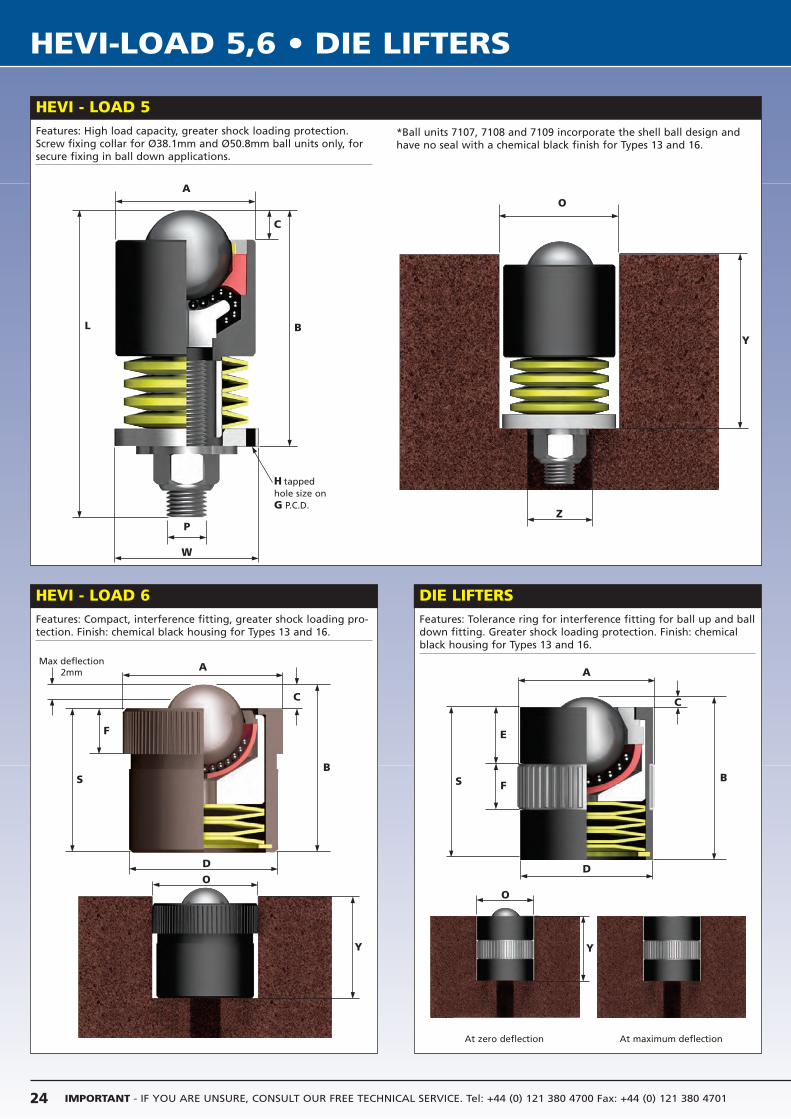
HEVI-LOAD 5,6 • DIE LIFTERS
HEVI - LOAD 5
HEVI - LOAD 6 DIE LIFTERS
Features: High load capacity, greater shock loading protection.Screw fixing collar for Ø38.1mm and Ø50.8mm ball units only, forsecure fixing in ball down applications.
Features: Tolerance ring for interference fitting for ball up and balldown fitting. Greater shock loading protection. Finish: chemicalblack housing for Types 13 and 16.
Features: Compact, interference fitting, greater shock loading pro-tection. Finish: chemical black housing for Types 13 and 16.
At zero deflection At maximum deflection
A
B
C
L
P
W
O
Y
Z
A
D
C
B
F
S
Max deflection2mm A
D
C
B
E
S F
H tappedhole size onG P.C.D.
O
Y
O
Y
*Ball units 7107, 7108 and 7109 incorporate the shell ball design andhave no seal with a chemical black finish for Types 13 and 16.
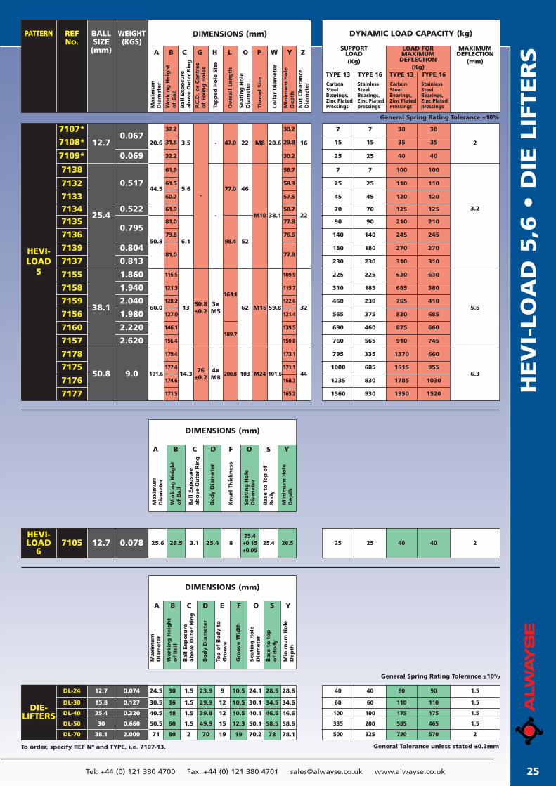
HEV
I-LO
AD
5,6
• D
IE L
IFTER
S
25Tel: +44 (0) 121 380 4700 Fax: +44 (0) 121 380 4701 [email protected] www.alwayse.co.uk
DIMENSIONS (mm)PATTERN REFNo.
BALLSIZE
(mm)
WEIGHT(KGS)
Maxim
um
Dia
mete
r
DYNAMIC LOAD CAPACITY (kg)
TYPE 13
Carbon Steel Bearings,Zinc PlatedPressingsW
ork
ing
Heig
ht
of
Ball
A B C G H L O P W Y Z
Overa
ll L
en
gth
Min
imu
m H
ole
Dep
th
Nu
t C
leara
nce
Dia
mete
r
TYPE 16
StainlessSteelBearings,Zinc PlatedpressingsB
all
Exp
osu
reab
ove O
ute
r R
ing
P.C
.D.
or
Cen
tres
of
Fixin
g H
ole
s
SUPPORTLOAD(Kg)
TYPE 13
Carbon Steel Bearings,Zinc PlatedPressings
TYPE 16
StainlessSteelBearings,Zinc Platedpressings
LOAD FORMAXIMUM
DEFLECTION(Kg)
MAXIMUM DEFLECTION
(mm)
Seati
ng
Ho
leD
iam
ete
r
Thre
ad
Siz
e
Co
llar
Dia
mete
r
7107*
7108*0.067
7109* 0.069
7138
7132
7133
0.517
71347135
7136
7139
7137
7155
7158
7159
7156
7160
7157
0.795
0.522
0.804
0.813
1.860
1.940
2.040
1.980
2.220
2.620
9.0
7178
7175
7176
7177
12.7
25.4
38.1
50.8
HEVI-LOAD
5
20.6 3.5 47.0
32.2
31.8
32.2
61.9
61.5
60.7
61.9
81.0
79.8
81.0
115.5
121.3
128.213
127.0
146.1
156.4
50.8±0.2
179.4
177.4
174.6
171.5
44.5-
50.8
5.6
6.1
77.0
98.4
60.0
161.1
101.6 14.376
±0.2200.8
189.7
22
46
52
62
103
M8
M10
M16
M24
20.6
38.1
59.8
101.6
30.2
29.8
30.2
58.7
58.3
57.5
58.7
77.8
76.6
77.8
109.9
115.7
122.6
121.4
139.5
150.8
173.1
171.1
168.3
165.2
16
22
32
44
7 7 30 30
15 15 35 35
25 25 40 40
7 7 100 100
25 25 110 110
45 45 120 120
70 70 125 125
90 90 210 210
140 140 245 245
180 180 270 270
310 185 685 380
460 230 765 410
565 375 830 685
690 460 875 660
760 565 910 745
795 335 1370 660
1000 685 1615 955
1235 830 1785 1030
1560 930 1950 1520
230 230 310
630
310
630
2
3.2
5.6
6.3
General Spring Rating Tolerance ±10%
DIMENSIONS (mm)
Maxim
um
Dia
mete
r
Wo
rkin
g H
eig
ht
of
Ball
A B C D F O S Y
Bo
dy D
iam
ete
r
Kn
url
Th
ickn
ess
Seati
ng
Ho
leD
iam
ete
r
Base
to
To
p o
fB
od
y
Min
imu
m H
ole
Dep
th
Ball
Exp
osu
reab
ove O
ute
r R
ing
25.6 28.5 3.1 25.4 825.4+0.15+0.05
25.4 26.5 25 25 40 40 2HEVI-LOAD
6
DIMENSIONS (mm)
Maxim
um
Dia
mete
r
Wo
rkin
g H
eig
ht
of
Ball
A B C D E F O S Y
Bo
dy D
iam
ete
r
Top
of
Bo
dy t
oG
roo
ve
Gro
ove W
idth
Seati
ng
Ho
leD
iam
ete
r
Base
to
to
po
f B
od
y
Min
imu
m H
ole
Dep
th
Ball
Exp
osu
reab
ove O
ute
r R
ing
7105 12.7 0.078
DIE-LIFTERS
DL-24
DL-30
DL-40
DL-50
DL-70
12.7
15.8
25.4
30
38.1
0.074
0.127
0.320
0.660
2.000
24.5
30.5
40.5
50.5
71
30
36
48
60
80
1.5
1.5
1.5
1.5
2
23.9
29.9
39.8
49.9
70
9
12
12
15
19
10.5
10.5
10.5
12.3
19
24.1
30.1
40.1
50.1
70.2
28.5
34.5
46.5
58.5
78
28.6
34.6
46.6
58.6
78.1
40 40 90 90 1.5
60 60 110 110 1.5
100 100 175 175 1.5
335 200 585 465 1.5
500 325 720 570 2
General Tolerance unless stated ±0.3mm
General Spring Rating Tolerance ±10%
Tap
ped
Ho
le S
ize
-
3xM5
-
4xM8
To order, specify REF Nº and TYPE, i.e. 7107-13.
225 225
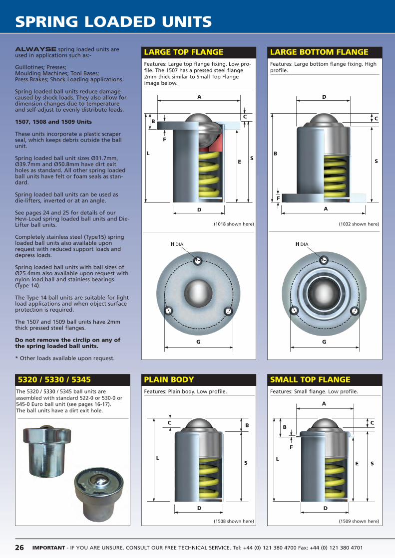
IMPORTANT - IF YOU ARE UNSURE, CONSULT OUR FREE TECHNICAL SERVICE. Tel: +44 (0) 121 380 4700 Fax: +44 (0) 121 380 470126
SPRING LOADED UNITS
ALWAYSE spring loaded units areused in applications such as:-
Guillotines; Presses;Moulding Machines; Tool Bases; Press Brakes; Shock Loading applications.
Spring loaded ball units reduce damagecaused by shock loads. They also allow fordimension changes due to temperatureand self-adjust to evenly distribute loads.
1507, 1508 and 1509 Units
These units incorporate a plastic scraperseal, which keeps debris outside the ballunit.
Spring loaded ball unit sizes Ø31.7mm,Ø39.7mm and Ø50.8mm have dirt exitholes as standard. All other spring loadedball units have felt or foam seals as stan-dard.
Spring loaded ball units can be used asdie-lifters, inverted or at an angle.
See pages 24 and 25 for details of ourHevi-Load spring loaded ball units and Die-Lifter ball units.
Completely stainless steel (Type15) springloaded ball units also available uponrequest with reduced support loads anddepress loads.
Spring loaded ball units with ball sizes ofØ25.4mm also available upon request withnylon load ball and stainless bearings(Type 14).
The Type 14 ball units are suitable for lightload applications and when object surfaceprotection is required.
The 1507 and 1509 ball units have 2mmthick pressed steel flanges.
Do not remove the circlip on any ofthe spring loaded ball units.
* Other loads available upon request.
PLAIN BODY
LARGE TOP FLANGE LARGE BOTTOM FLANGE
SMALL TOP FLANGE
Features: Large top flange fixing. Low pro-file. The 1507 has a pressed steel flange2mm thick similar to Small Top Flangeimage below.
Features: Large bottom flange fixing. Highprofile.
Features: Plain body. Low profile. Features: Small flange. Low profile.
A
C
F
SL
B
D
E
A
G G
C
F
SL
B
D
C
SL
B
D
D
C
SB
A
H DIA H DIA
F
E
(1018 shown here)
(1508 shown here)
5320 / 5330 / 5345The 5320 / 5330 / 5345 ball units are assembled with standard 522-0 or 530-0 or 545-0 Euro ball unit (see pages 16-17). The ball units have a dirt exit hole.
(1032 shown here)
(1509 shown here)
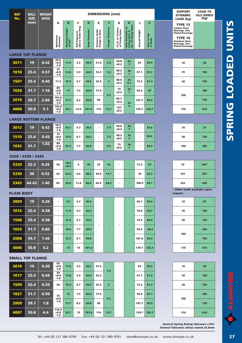
SPR
ING
LO
AD
ED
UN
ITS
27Tel: +44 (0) 121 380 4700 Fax: +44 (0) 121 380 4701 [email protected] www.alwayse.co.uk
General Spring Rating Tolerance ±10%General Tolerance unless stated ±0.3mm
DIMENSIONS (mm)BALL SIZE(mm)
WEIGHT(KGS)
REFNo.
LOAD TOFULLY DEPRESS
(kg)
SUPPORTDYNAMICLOAD (kg)
A B C D E F G H L S
Maxim
um
Dia
mete
r
Wo
rkin
g H
eig
ht
of
Ball
Ball
Exp
osu
reab
ove O
ute
r R
ing
Bo
dy D
iam
ete
r
Dis
tan
ce U
nd
er
Flan
ge t
o B
ase
Flan
ge T
hic
kn
ess
P.C
.D.
or
Cen
tres
of
Fixin
g H
ole
s
Ho
le D
iam
ete
r o
fFi
xin
g H
ole
s &
N
o.
of
Fixin
g H
ole
s
Overa
ll H
eig
ht
Base
to
To
p
of
Bo
dy
3011 0.42
0.57
19
25.4
66.6+0.0-1.0
75+0.0-1.0
11.4
13.8
19.3
3.5
5.9
6.7
36.5
44.5
44.5
51.6
53.3
52.9
50.8±0.2
60.3±0.2
3x7
60.4±0.2
2x5.1
63
67.1
72.2
59.5
61.2
61.3
30
160*
100
130
10
60*
35
50
7.9
60.4
3x7
7.9
2
1018
0.4025.4 71.31507
LARGE TOP FLANGE
TYPE 13Carbon SteelBearings, ZincPlated Pressings
TYPE 16Stainless SteelBearings, ZincPlated Pressings
170
410
180
170
100
1.16
2.04
5.1
31.7
39.7
50.8
101.6+0.0-1.0
152.4+0.0-1.0
89+0.0-1.0
17.7
25.7
17
8.2
13.0
7.5
69.8
101.6
60.0
90
114
77.573
±0.2
85.7±0.2
127±0.2
3x9
3x7
94.5
139.7
107.7
87
126.7
99.5
12.7
9.5
1028
2010
4008
PLAIN BODY
3009 0.26
0.38
0.38
1.46
0.86
4.2
19
25.4
25.4
39.7
31.7
50.8
-
-
-
-
-
-
9.5
11.9
12.7
10.4
13
12.5
4.7
6.3
9.1
7.7
13
6.7
36.5
44.5
69.8
60.0
101.6
44.5
- - - -
65.1
70.6
72.9
139.7
107.6
94.5
55.6
58.7
60.4
126.7
94.9
84.9
35
140
200
190
410
130
10
35
170
100
50
1016
1508
2008
1026
4006
SMALL TOP FLANGE
30
100
180
170
410
130
10
35
170
100
50
3010 0.30
0.44
0.99
0.39
1.8
4.4
19
25.4
31.7
25.4
39.7
50.8
45+0.0-1.050
+0.0-1.0
114.3+0.0-1.0
75+0.0-1.0
56
11.4
13.8
17.7
25.7
17
19.3
3.5
5.9
8.2
13
7.5
6.7
36.5
44.5
69.8
101.6
60.0
44.5
51.6
53.3
90
114
77.5
52.9
7.9
12.7
9.5
2
- -
63
67.1
94.6
72.2
139.7
107.7
59.5
61.2
87.1
61.3
126.7
99.5
1017
1027
1509
2009
4007
LARGE BOTTOM FLANGE
35
130
200100
10
50
66.6+0.0-1.0
65.1 4.7 36.5 -50.8±0.2
3x7
- 55.67.90.42193012
75+0.0-1.0
72.9 6.7 44.5 - 7.960.3±0.2
73±0.2
3x7
3x7
-0.4525.41510
89+0.0-1.0
95.3 7.7 60.0 - 9.5 - 84.91.02
31.71032
5320 / 5330 / 5345
5320 22.2 0.26 5018.5±0.2
4 39 33 51.5 47
5330
5345
30
44.45
0.52
1.40
62
85 35.6
24.4 6.6
11.4
48.2
66.4
45.6
64.9
14
17.7
24.2
-
-
-
-
-
- 70
100.5
63.3
89.1
130
200
232
72
141
* Other loads available uponrequest.
160*
201
420
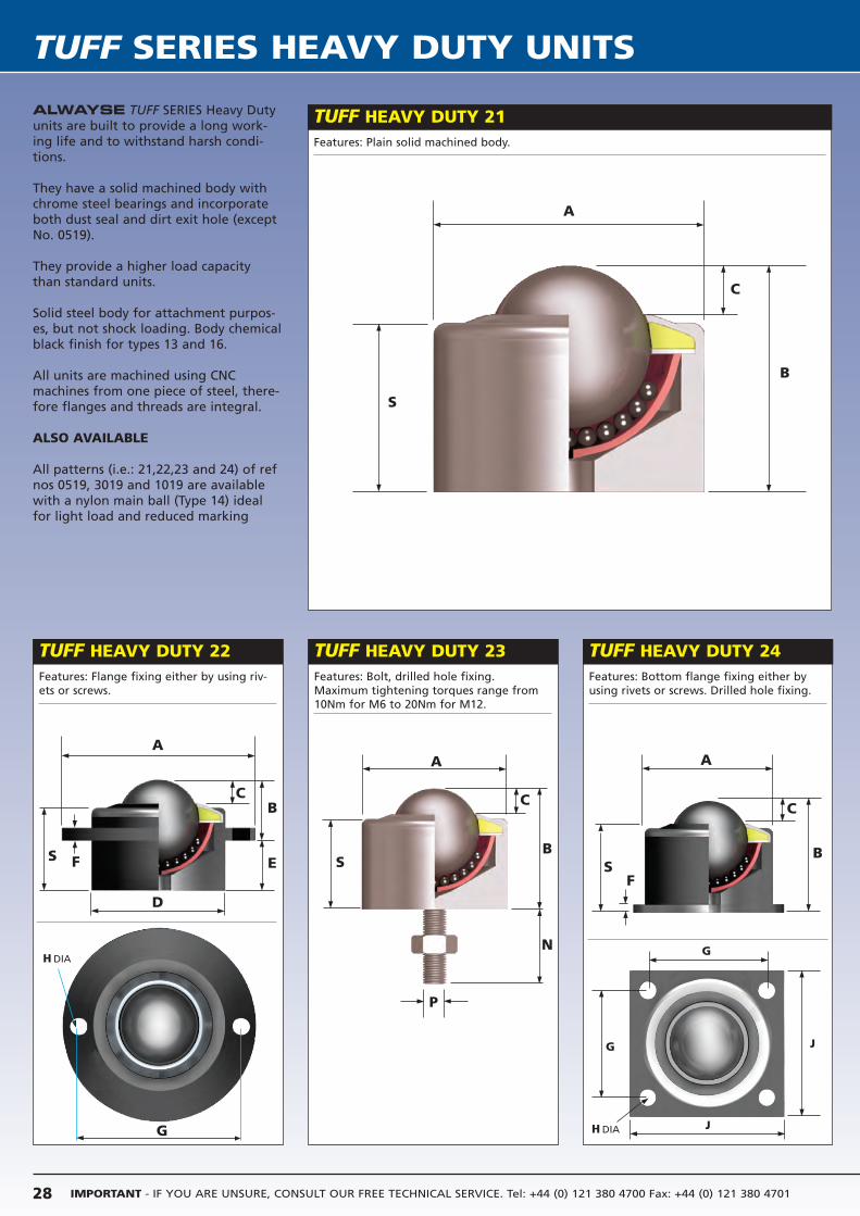
IMPORTANT - IF YOU ARE UNSURE, CONSULT OUR FREE TECHNICAL SERVICE. Tel: +44 (0) 121 380 4700 Fax: +44 (0) 121 380 470128
TUFF SERIES HEAVY DUTY UNITS
TUFF HEAVY DUTY 23 TUFF HEAVY DUTY 24
TUFF HEAVY DUTY 21ALWAYSE TUFF SERIES Heavy Dutyunits are built to provide a long work-ing life and to withstand harsh condi-tions.
They have a solid machined body withchrome steel bearings and incorporateboth dust seal and dirt exit hole (exceptNo. 0519).
They provide a higher load capacitythan standard units.
Solid steel body for attachment purpos-es, but not shock loading. Body chemicalblack finish for types 13 and 16.
All units are machined using CNCmachines from one piece of steel, there-fore flanges and threads are integral.
ALSO AVAILABLE
All patterns (i.e.: 21,22,23 and 24) of refnos 0519, 3019 and 1019 are availablewith a nylon main ball (Type 14) idealfor light load and reduced marking
TUFF HEAVY DUTY 22
Features: Plain solid machined body.
Features: Flange fixing either by using riv-ets or screws.
Features: Bolt, drilled hole fixing.Maximum tightening torques range from10Nm for M6 to 20Nm for M12.
Features: Bottom flange fixing either byusing rivets or screws. Drilled hole fixing.
A
B
C
S
A
D
B
E
C
S F
A
B
N
P
C
S
A
B
C
SF
G
G
J
J
G H DIA
H DIA
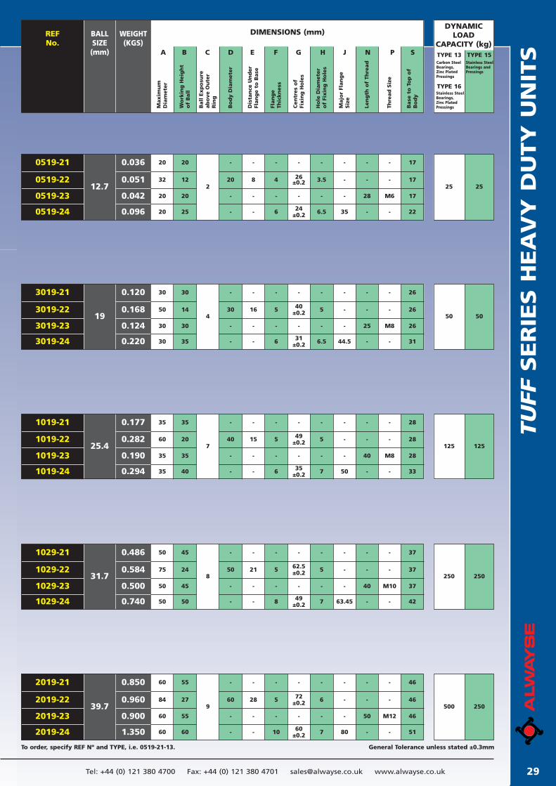
TU
FF
SER
IES H
EA
VY
DU
TY
UN
ITS
29Tel: +44 (0) 121 380 4700 Fax: +44 (0) 121 380 4701 [email protected] www.alwayse.co.uk
General Tolerance unless stated ±0.3mmTo order, specify REF Nº and TYPE, i.e. 0519-21-13.
DIMENSIONS (mm)REFNo.
BALL SIZE(mm)
WEIGHT(KGS)
Maxim
um
Dia
mete
r
DYNAMICLOAD
CAPACITY (kg)A B C D E F G H J N P S
Wo
rkin
g H
eig
ht
of
Ball
Ball
Exp
osu
reab
ove O
ute
rR
ing
Bo
dy D
iam
ete
r
Dis
tan
ce U
nd
er
Flan
ge t
o B
ase
Flan
ge
Thic
kn
ess
Cen
tres
of
Fixin
g H
ole
s
Ho
le D
iam
ete
ro
f Fi
xin
g H
ole
s
Majo
r Fl
an
ge
Siz
e
Len
gth
of
Thre
ad
Thre
ad
Siz
e
Base
to
To
p o
fB
od
y
TYPE 13 TYPE 15Carbon SteelBearings, Zinc Plated Pressings
Stainless SteelBearings andPressings
TYPE 16Stainless SteelBearings, Zinc Plated Pressings
-
20
-
-
-
8
-
-
-
4
-
6
-
26±0.2
-
24±0.2
-
3.5
-
6.5
-
-
28
-
-
-
M6
-
-
-
-
35
20
32
20
20
20
212
20
25
0519-21
0519-22
0519-23
0519-24
0.036
0.051
0.042
0.096
12.7 25 25
17
17
17
22
50 50
-
30
-
-
-
16
-
-
-
5
-
6
-
40±0.2
-
31±0.2
-
5
-
6.5
-
-
25
-
-
-
M8
-
26
26
26
31
-
-
-
44.5
30
30
30
30
414
30
35
3019-21
3019-22
3019-23
3019-24
0.120
0.168
0.124
0.220
19
125 125
-
40
-
-
-
15
-
-
-
5
-
6
-
49±0.2
-
35±0.2
-
5
-
7
-
-
40
-
-
-
M8
-
28
28
28
33
-
-
-
50
35
60
35
35
35
720
35
40
1019-21
1019-22
1019-23
1019-24
0.177
0.282
0.190
0.294
25.4
250 250
-
50
-
-
-
21
-
-
-
5
-
8
-
62.5±0.2
-
49±0.2
-
5
-
7
-
-
40
-
-
-
M10
-
37
37
37
42
-
-
-
63.45
50
75
50
50
45
824
45
50
1029-21
1029-22
1029-23
1029-24
0.486
0.584
0.500
0.740
31.7
500 250
-
60
-
-
-
28
-
-
-
5
-
10
-
72±0.2
-
60±0.2
-
6
-
7
-
-
50
-
-
-
M12
-
46
46
46
51
-
-
-
80
60
84
60
60
55
927
55
60
2019-21
2019-22
2019-23
2019-24
0.850
0.960
0.900
1.350
39.7
50
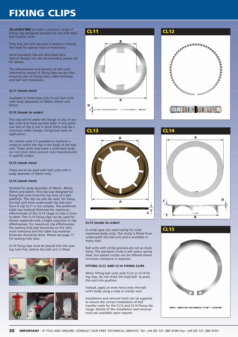
IMPORTANT - IF YOU ARE UNSURE, CONSULT OUR FREE TECHNICAL SERVICE. Tel: +44 (0) 121 380 4700 Fax: +44 (0) 121 380 470130
FIXING CLIPS
ALWAYSE provide a complete range offixing clips designed specially for use with theirball transfer units.
They lock the unit securely in position withoutthe need for special tools or machinery.
Some standard clips are described here.Special designs can also be provided, please askfor details.
The effectiveness and security of ball unitsattached by means of fixing clips can be influ-enced by size of fixing holes, table thicknessand ball unit tolerances.
CL11 (stock item)
Available in three sizes only to suit ball unitswith body diameters of 36mm, 45mm and62mm.
CL12 (made to order)
This clip will fit under the flange of any of ourball units that have parallel sides. If any partic-ular size of clip is not in stock there may be aminimum order charge. Fixing hole sizes onapplication.
On certain units it is possible to machine arecess to retain the clip in the body of the ballunit. These units must have a solid steel body,are not stock items and are only manufacturedto specific orders.
CL13 (stock item)
These are to be used with ball units with abody diameter of 24mm only.
CL14 (stock item)
Stocked for body diameter of 24mm, 36mm,45mm and 62mm. This clip was designed forfixing ball units from the top face of a ballplatform. The clip can also be used for fixingthe ball unit from underneath the ball plat-form if clip CL11 is not suitable. The preferredtable top material thickness for maximumeffectiveness of the CL14 range of clips is 2mmto 4mm. The CL14 fixing clips can be used forthicker materials with a slight reduction in clipeffectiveness. For maximum clip effectivenessthe seating hole size should be on the mini-mum tolerance and the table top materialthickness should be 4mm. Please see page 17for seating hole sizes
CL14 fixing clips must be placed into the seat-ing hole first, before the ball unit is fitted.
CL13
CL15
CL14
CL11 CL12
CL15 (made to order)
A circlip type clip used mainly for solidmachined body units. The circlip is fitted fromunderneath the ball unit and is available inmany sizes.
Ball units with circlip grooves are not ex stockitems. The standard circlip is self colour springsteel, but plated circlips can be offered wherecorrosion resistance is required.
FITTING CL12 AND CL14 FIXING CLIPS
When fitting ball units with CL12 or CL14 fix-ing clips, do not strike the load ball to pressthe unit into position.
Instead, apply an even force onto the ballunit’s body using a tube or similar tool.
Installation and removal tools can be suppliedto ensure the correct installation of balltransfer units for the CL12 and CL14 fixing cliprange. Details of the installation and removaltools are available upon request.
B
D
A
B
A
C
A
B
C D
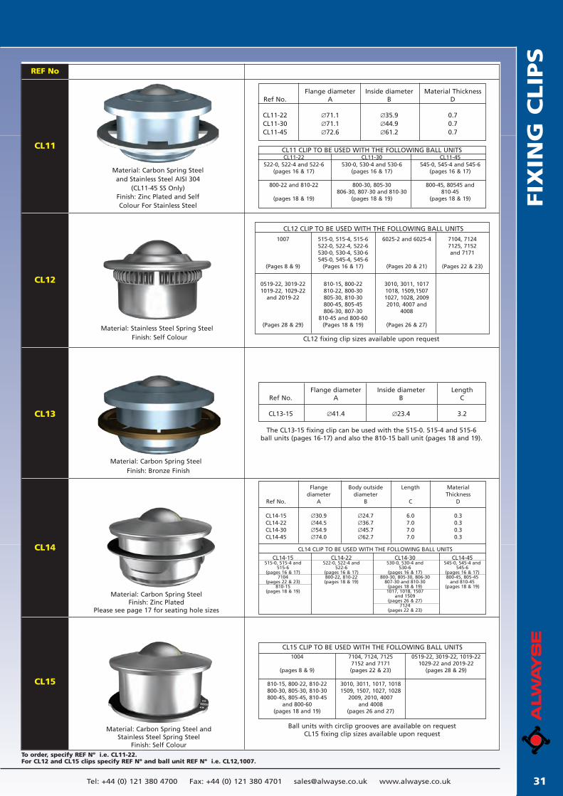
FIX
ING
CLIP
S
31Tel: +44 (0) 121 380 4700 Fax: +44 (0) 121 380 4701 [email protected] www.alwayse.co.uk
To order, specify REF Nº i.e. CL11-22.For CL12 and CL15 clips specify REF Nº and ball unit REF Nº i.e. CL12,1007.
CL11
CL12
REF No
CL13
CL14
CL15
Flange diameter Inside diameter Material ThicknessRef No. A B D
CL11-22 ∅71.1 ∅35.9 0.7CL11-30 ∅71.1 ∅44.9 0.7CL11-45 ∅72.6 ∅61.2 0.7
CL11 CLIP TO BE USED WITH THE FOLLOWING BALL UNITSCL11-22 CL11-30 CL11-45
522-0, 522-4 and 522-6 530-0, 530-4 and 530-6 545-0, 545-4 and 545-6(pages 16 & 17) (pages 16 & 17) (pages 16 & 17)
800-22 and 810-22 800-30, 805-30 800-45, 80545 and806-30, 807-30 and 810-30 810-45
(pages 18 & 19) (pages 18 & 19) (pages 18 & 19)
CL12 CLIP TO BE USED WITH THE FOLLOWING BALL UNITS
1007 515-0, 515-4, 515-6 6025-2 and 6025-4 7104, 7124522-0, 522-4, 522-6 7125, 7152530-0, 530-4, 530-6 and 7171545-0, 545-4, 545-6
(Pages 8 & 9) (Pages 16 & 17) (Pages 20 & 21) (Pages 22 & 23)
0519-22, 3019-22 810-15, 800-22 3010, 3011, 10171019-22, 1029-22 810-22, 800-30 1018, 1509,1507
and 2019-22 805-30, 810-30 1027, 1028, 2009800-45, 805-45 2010, 4007 and806-30, 807-30 4008
810-45 and 800-60(Pages 28 & 29) (Pages 18 & 19) (Pages 26 & 27)
Flange diameter Inside diameter LengthRef No. A B C
CL13-15 ∅41.4 ∅23.4 3.2
The CL13-15 fixing clip can be used with the 515-0. 515-4 and 515-6ball units (pages 16-17) and also the 810-15 ball unit (pages 18 and 19).
Flange Body outside Length Materialdiameter diameter Thickness
Ref No. A B C D
CL14-15 ∅30.9 ∅24.7 6.0 0.3CL14-22 ∅44.5 ∅36.7 7.0 0.3CL14-30 ∅54.9 ∅45.7 7.0 0.3CL14-45 ∅74.0 ∅62.7 7.0 0.3
CL14 CLIP TO BE USED WITH THE FOLLOWING BALL UNITS
CL14-15 CL14-22 CL14-30 CL14-45515-0, 515-4 and 522-0, 522-4 and 530-0, 530-4 and 545-0, 545-4 and
515-6 522-6 530-6 545-6(pages 16 & 17) (pages 16 & 17) (pages 16 & 17) (pages 16 & 17)
7104 800-22, 810-22 800-30, 805-30, 806-30 800-45, 805-45(pages 22 & 23) (pages 18 & 19) 807-30 and 810-30 and 810-45
810-15 (pages 18 & 19) (pages 18 & 19)(pages 18 & 19) 1017, 1018, 1507
and 1509(pages 26 & 27)
7124(pages 22 & 23)
CL15 CLIP TO BE USED WITH THE FOLLOWING BALL UNITS1004 7104, 7124, 7125 0519-22, 3019-22, 1019-22
7152 and 7171 1029-22 and 2019-22(pages 8 & 9) (pages 22 & 23) (pages 28 & 29)
810-15, 800-22, 810-22 3010, 3011, 1017, 1018800-30, 805-30, 810-30 1509, 1507, 1027, 1028800-45, 805-45, 810-45 2009, 2010, 4007
and 800-60 and 4008(pages 18 and 19) (pages 26 and 27)
CL12 fixing clip sizes available upon request
Ball units with circlip grooves are available on requestCL15 fixing clip sizes available upon request
Material: Stainless Steel Spring Steel
Material: Carbon Spring Steel
Material: Carbon Spring SteelFinish: Zinc Plated
Please see page 17 for seating hole sizes
Material: Carbon Spring Steel andStainless Steel Spring Steel
Finish: Self Colour
Material: Carbon Spring Steel
and Stainless Steel AISI 304
(CL11-45 SS Only)
Finish: Zinc Plated and Self Colour For Stainless Steel
Finish: Self Colour
Finish: Bronze Finish
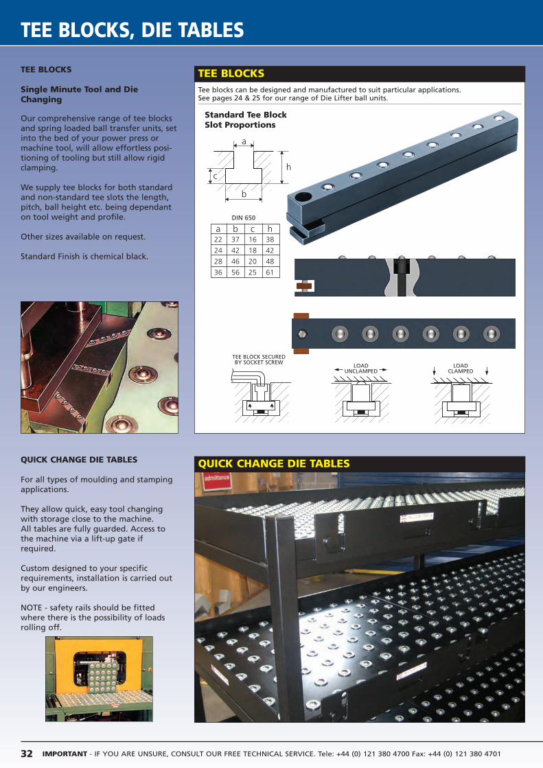
IMPORTANT - IF YOU ARE UNSURE, CONSULT OUR FREE TECHNICAL SERVICE. Tele: +44 (0) 121 380 4700 Fax: +44 (0) 121 380 470132
TEE BLOCKS, DIE TABLES
TEE BLOCKS
Single Minute Tool and DieChanging
Our comprehensive range of tee blocksand spring loaded ball transfer units, setinto the bed of your power press ormachine tool, will allow effortless posi-tioning of tooling but still allow rigidclamping.
We supply tee blocks for both standardand non-standard tee slots the length,pitch, ball height etc. being dependanton tool weight and profile.
Other sizes available on request.
Standard Finish is chemical black.
QUICK CHANGE DIE TABLES
For all types of moulding and stampingapplications.
They allow quick, easy tool changingwith storage close to the machine.All tables are fully guarded. Access tothe machine via a lift-up gate ifrequired.
Custom designed to your specificrequirements, installation is carried outby our engineers.
NOTE - safety rails should be fittedwhere there is the possibility of loadsrolling off.
a b c h22 37 16 38
24 42 18 42
28 46 20 48
36 56 25 61
Standard Tee Block Slot Proportions
Tee blocks can be designed and manufactured to suit particular applications.See pages 24 & 25 for our range of Die Lifter ball units.
TEE BLOCKS
DIN 650
QUICK CHANGE DIE TABLES
a
c
b
h
LOADUNCLAMPED
LOADCLAMPED
TEE BLOCK SECUREDBY SOCKET SCREW
ALWAYSE ENGINEERING LIMITEDMILLER STREET BIRMINGHAM B6 4NF ENGLANDTelephone: 0121 380 4700 + 44 (0) 121 380 4700
Fax: 0121 380 4701 + 44 (0) 121 380 4701web: www.alwayse.co.uk email: [email protected]
Prin
ted
in E
ngla
nd M
INO
R A
ME
ND
S F
OR
RE
PR
INT
AU
GU
ST
2014
ALWAYSE