1 autonomously controlled vehicles with collision avoidance mike gregoire rob beauchamp dan holcomb...
Post on 19-Dec-2015
216 views
TRANSCRIPT

1
Autonomously Controlled Vehicles with Collision Avoidance
Mike Gregoire Rob BeauchampDan HolcombTim Brett

2
Motivation
Follow and Avoid Collisions Simulated Highway Driving Environment Autonomous Not Centralized
Centralized System Not Practical for Today's Highways Predictable Vehicle Behavior
First Car Moves, Others Follow

3
System Block Diagram
Ultrasonic Sensor Scans Area in Front of Vehicle for Objects
Controller Receives Distance and Angle Information from Sensor and
Decides what to do
The Controller Interfaces to the Platform to Drive the Vehicle
4
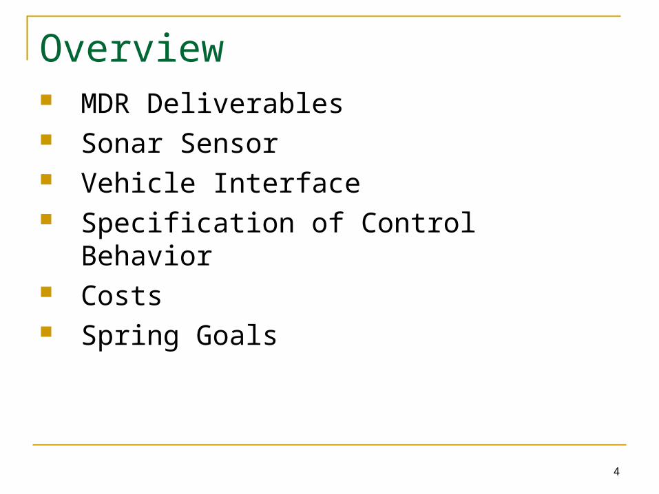
Overview MDR Deliverables Sonar Sensor Vehicle Interface Specification of Control Behavior Costs Spring Goals

5
MDR Deliverables Functional Sonar Sensor
Distance Direction
Platform Interface to Control Vehicle Motor (Speed) Actuator (Turning)
Specification of Control Behavior

6
Functional Sonar Sensor• Sonar vs. Optical
• Chose Sonar• Precise Distance
Measurement Is Not As Important as Relative Distance
• Minimum Range is 1.1 ft due to Ringing in Receiver
• Maximum Range is > 8.36ft (for a ceiling) but a Software Limit of 5.5ft is imposed
Sonar
Optical

7
Sensor Graphs – Ceiling (Stationary)
Speed Of Sound = 1100 ft/s
Left Channel Median
~ 7550µs
=49.83 Inches
Right Channel Median
~ 7570µs
=49.96 Inches
150µs Error is a 1 Inch Error in Measured Distance

8
Sensor Graphs – 2x4 (Moving)
Distance
0
5
10
15
20
25
0 100 200 300 400 500 600 700 800
Inch
es
L
R
Difference (Left - Right)
-250
-200
-150
-100
-50
050
100
150
200
250
0 100 200 300 400 500 600 700 800
Tim
e (uS
ec)
2x4 Board Moving Left to Right over Sensor
The Difference Graph Shows Discreteness in Time. Differences Are Equal to 1 Period (25µs)
Can See Precise Angle Change using Difference Modulo Period
Difference Modulo 25
0
5
10
15
20
25
0 100 200 300 400 500 600 700 800
Tim
e (uS
ec)

9
Sensor Graphs – Error and Reliability
-12 -6 0 6 1212 Inches
18 Inches
24 Inches
Distance Off Center (Inches)
Contour - Percentage of Good Data Points
0.950-1.000
0.900-0.950
0.850-0.900
0.800-0.850
0.750-0.800
0.700-0.750
0.650-0.700
0.600-0.650
0.550-0.600
0.500-0.550
• 15 Discrete Distances – 1000 Measurements at Each
• Software Filter on Sensor Qualifies each Point. Counter has to be between 2000us and 8000us with a Difference between -160us and 160us.
• Contour Shows Percentage of Points out of 1000 that are within Filter Limits
• Recreation of position has large error because of inaccuracy in the angle measurement. This is because the same wave front doesn’t trigger both sensors. Using Mod 25 gives accurate change in angle but not an absolute angle.
Measured Position vs Calculated
0
5
10
15
20
25
30
-20 -15 -10 -5 0 5 10 15 20
Inches
Inch
es
Calculated
Measured Left
Measured Middle
Measured Right

10
Platform Interface No Schematics Available Need to Reverse Engineer Controls
Motor for Speed Actuator for Steering
Direct Interface Simplest Solution

11
Platform Interface - Speed Motor Interface Uses Two Wires
One Wire Tied to Ground One Wire Connected to PIC Through Current Driver
PIC Outputs Using Pulse Width Modulation (PWM) 24µs PWM Period → 41.667kHZ Frequency 96 Discrete Duty Cycles with 4MHZ PIC Clock
Need to Overcome Motor Inertia when Stopped

12
Platform Interface - Turning Actuator Interface Uses Four Wires
2 Wires Used For VDD and GND 2 Wires From PIC Output Control Left / Right Turns
Control Wires at Opposite Voltage Steps Actuator Length of Voltage Differential → Length of Turn 20ms For Turn From Center to Full Left / Right Angle Turned is Surface Dependent

13
Platform Interface Movie

14
Platform Interface Movie

15
Control Behavior
Follower should Not Always Drive Directly Towards Leader
Follower should Trace the Path of the Leader
Bad Turn Good Turn

16
Control Behavior
Proposal: Use a FIFO Instruction Queue For each Sensor Data Point, a New
Instruction is Loaded into FIFO When Instruction Reaches Head, Follower
Occupies the Same Point as Lead Car When Instruction Entered FIFO

17
MDR Deliverables
Functional Sonar Sensor Distance Direction
Platform Interface to Control Vehicle Motor (Speed) Actuator (Turning)
Specification of Control Behavior

18
Product Costs $500 Total Budget Fall Expenses ≈ $150
3 Vehicles For Free Ultrasonic Transducers ≈ $50 Op-Amps, PICs, Drivers, Etc. ≈ $100
Spring Expenses 2 More Vehicles ≈ $100 Ultrasonic Transducers ≈ $50 $200 for Unforeseen and Misc. Parts

19
Spring Goals Integration of Systems
Communication From Sensor to Platform Controller Three Functional Vehicles
2 With Our System Refine Sensors
Variable Gain to Help Filter Noise Perform Demonstration
Lead Car Driven via Remote Two Autonomous Vehicles Accurately Follow

20
Thank You
Questions?

21
SupplementalDifference vs Angle
3 Inch Receiver Seperation - 36 Inches Away
0.00
50.00
100.00
150.00
200.00
250.00
0 10 20 30 40 50 60 70 80 90
Angle (Degrees)
Tim
e (u
Sec
)
Amplifier 2 Stage -5V to +5V Amp With a Maximum Gain of 1406 V/V With A DC offset of -1V Output Put into a GND to +5V Amp With a Maximum Gain 37.5 V/V