1 arm university program copyright © arm ltd 2013 cortex-m4 cpu core
TRANSCRIPT
1ARM University ProgramCopyright © ARM Ltd 2013
Cortex-M4 CPU Core
2ARM University ProgramCopyright © ARM Ltd 2013
Overview Cortex-M4 Processor Core Registers
Memory System and Addressing
Thumb Instruction Set
3ARM University ProgramCopyright © ARM Ltd 2013
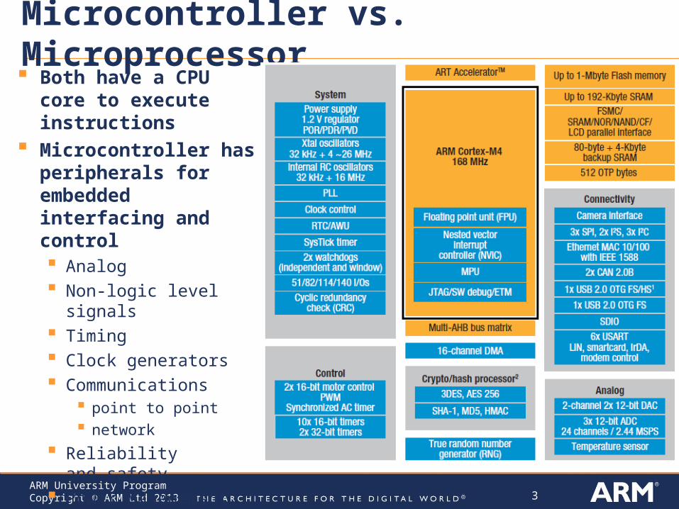
Microcontroller vs. Microprocessor Both have a CPU core
to execute instructions Microcontroller has
peripherals for embedded interfacing and control Analog Non-logic level
signals Timing Clock generators Communications
point to point network
Reliability and safety
Power Management
4ARM University ProgramCopyright © ARM Ltd 2013
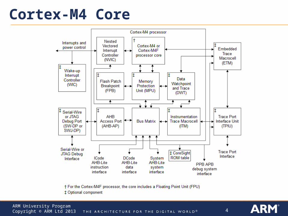
Cortex-M4 Core
5ARM University ProgramCopyright © ARM Ltd 2013
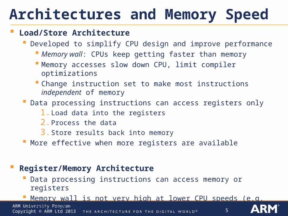
Architectures and Memory Speed Load/Store Architecture
Developed to simplify CPU design and improve performance Memory wall: CPUs keep getting faster than memory Memory accesses slow down CPU, limit compiler optimizations Change instruction set to make most instructions independent of memory
Data processing instructions can access registers only1. Load data into the registers
2. Process the data
3. Store results back into memory
More effective when more registers are available
Register/Memory Architecture Data processing instructions can access memory or registers Memory wall is not very high at lower CPU speeds (e.g. under 50 MHz)
6ARM University ProgramCopyright © ARM Ltd 2013
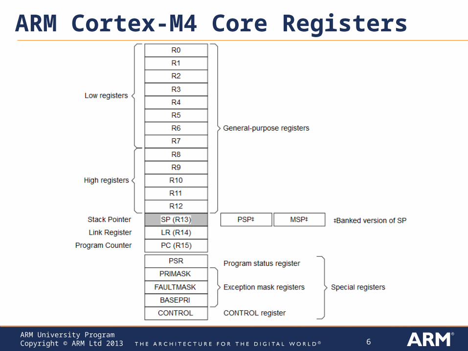
ARM Cortex-M4 Core Registers
7ARM University ProgramCopyright © ARM Ltd 2013
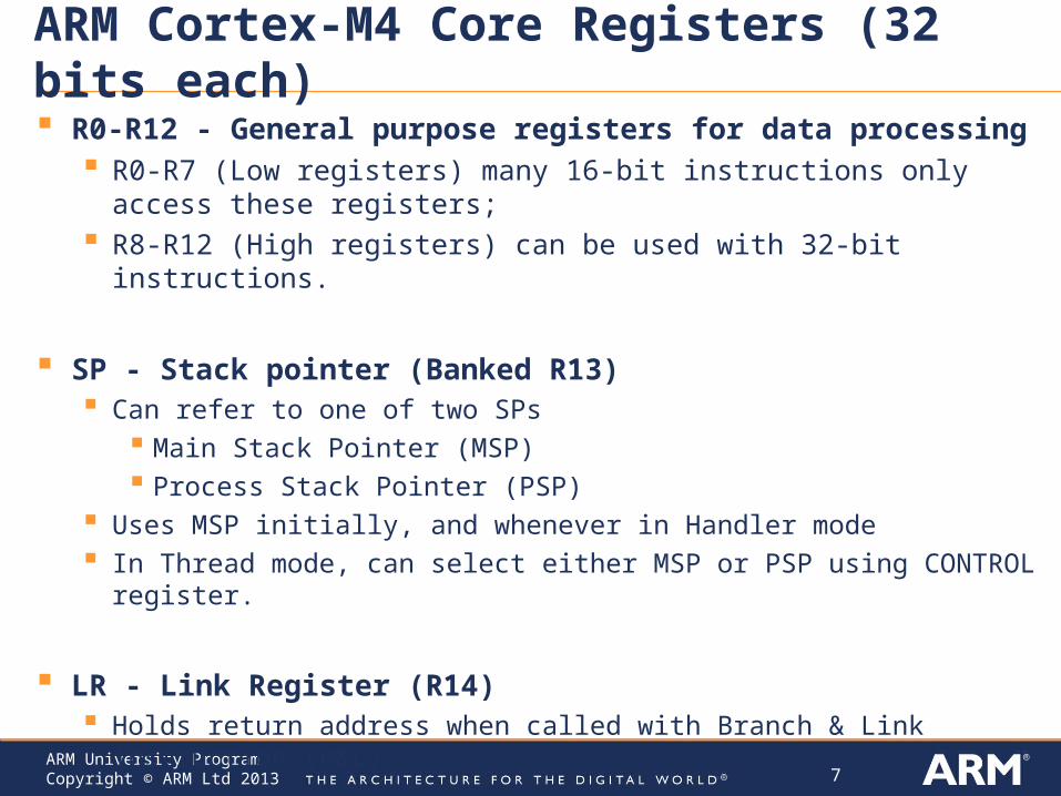
ARM Cortex-M4 Core Registers (32 bits each)
R0-R12 - General purpose registers for data processing R0-R7 (Low registers) many 16-bit instructions only access these registers; R8-R12 (High registers) can be used with 32-bit instructions.
SP - Stack pointer (Banked R13) Can refer to one of two SPs
Main Stack Pointer (MSP) Process Stack Pointer (PSP)
Uses MSP initially, and whenever in Handler mode In Thread mode, can select either MSP or PSP using CONTROL register.
LR - Link Register (R14) Holds return address when called with Branch & Link instruction (B&L)
PC - program counter (R15)
8ARM University ProgramCopyright © ARM Ltd 2013
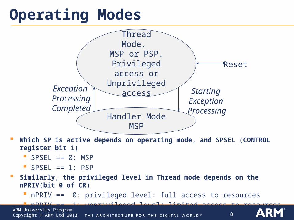
Operating Modes
Which SP is active depends on operating mode, and SPSEL (CONTROL register bit 1)
SPSEL == 0: MSP SPSEL == 1: PSP
Similarly, the privileged level in Thread mode depends on the nPRIV(bit 0 of CR)
nPRIV == 0: privileged level: full access to resources nPRIV == 1: unprivileged level: limited access to resources
ThreadMode.
MSP or PSP.Privileged access or Unprivileged access
Handler ModeMSP
Reset
Starting Exception Processing
Exception ProcessingCompleted
9ARM University ProgramCopyright © ARM Ltd 2013
ARM Cortex-M4 Special Registers
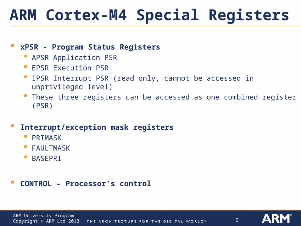
xPSR - Program Status Registers APSR Application PSR EPSR Execution PSR IPSR Interrupt PSR (read only, cannot be accessed in unprivileged level) These three registers can be accessed as one combined register (PSR)
Interrupt/exception mask registers PRIMASK FAULTMASK BASEPRI
CONTROL – Processor’s control
10ARM University ProgramCopyright © ARM Ltd 2013
ARM Cortex-M4 Program Status Register
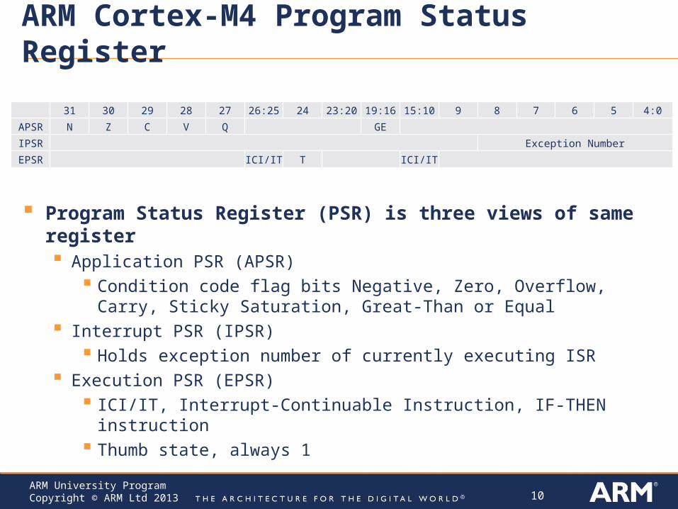
Program Status Register (PSR) is three views of same register Application PSR (APSR)
Condition code flag bits Negative, Zero, Overflow, Carry, Sticky Saturation, Great-Than or Equal
Interrupt PSR (IPSR) Holds exception number of currently executing ISR
Execution PSR (EPSR) ICI/IT, Interrupt-Continuable Instruction, IF-THEN instruction Thumb state, always 1
31 30 29 28 27 26:25 24 23:20 19:16 15:10 9 8 7 6 5 4:0
APSR N Z C V Q GE
IPSR Exception Number
EPSR ICI/IT T ICI/IT
11ARM University ProgramCopyright © ARM Ltd 2013
ARM Cortex-M4 Interrupt/exception mask registers
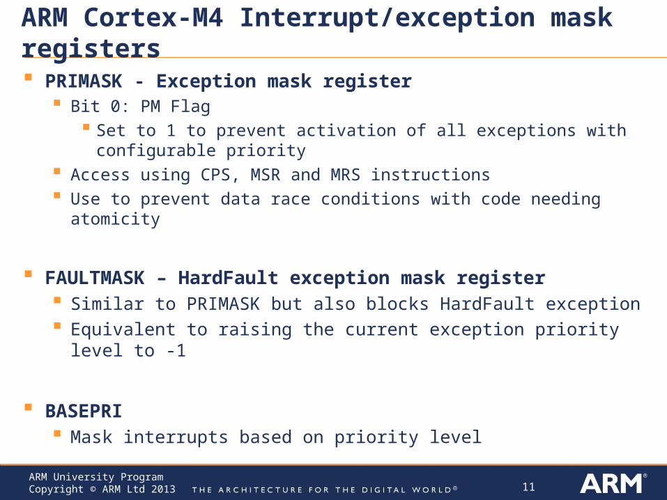
PRIMASK - Exception mask register Bit 0: PM Flag
Set to 1 to prevent activation of all exceptions with configurable priority Access using CPS, MSR and MRS instructions Use to prevent data race conditions with code needing atomicity
FAULTMASK – HardFault exception mask register Similar to PRIMASK but also blocks HardFault exception Equivalent to raising the current exception priority level to -1
BASEPRI Mask interrupts based on priority level
12ARM University ProgramCopyright © ARM Ltd 2013
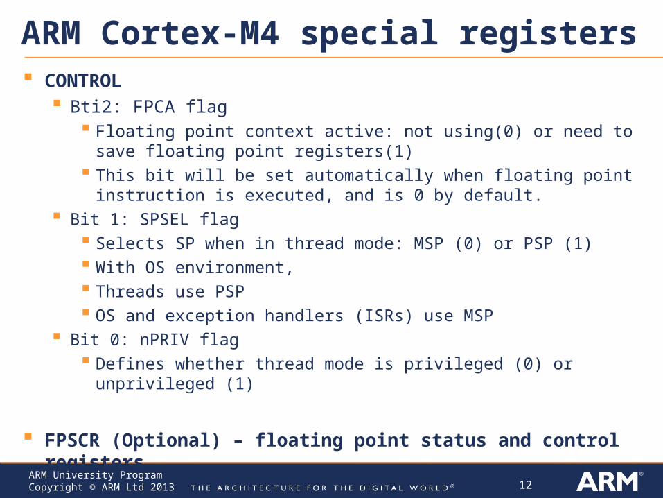
ARM Cortex-M4 special registers CONTROL
Bti2: FPCA flag Floating point context active: not using(0) or need to save floating point
registers(1) This bit will be set automatically when floating point instruction is executed,
and is 0 by default. Bit 1: SPSEL flag
Selects SP when in thread mode: MSP (0) or PSP (1) With OS environment, Threads use PSP OS and exception handlers (ISRs) use MSP
Bit 0: nPRIV flag Defines whether thread mode is privileged (0) or unprivileged (1)
FPSCR (Optional) – floating point status and control registers
13ARM University ProgramCopyright © ARM Ltd 2013
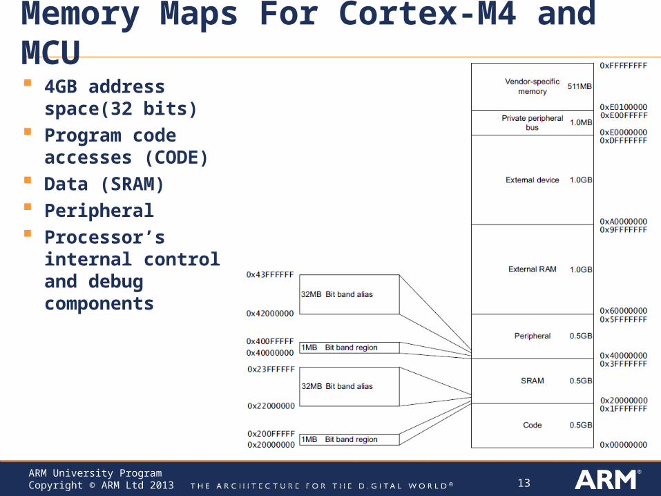
Memory Maps For Cortex-M4 and MCU
4GB address space(32 bits)
Program code accesses (CODE)
Data (SRAM) Peripheral Processor’s internal
control and debug components
14ARM University ProgramCopyright © ARM Ltd 2013
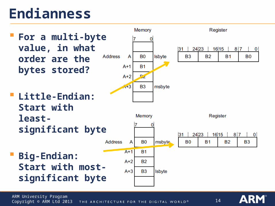
Endianness
For a multi-byte value, in what order are the bytes stored?
Little-Endian: Start with least-significant byte
Big-Endian: Start with most-significant byte
15ARM University ProgramCopyright © ARM Ltd 2013
ARMv7E-M Endianness
Cortex-M4 support both Little-Endianness and Big-Endianness
Instructions are always little-endian
Loads and stores to Private Peripheral Bus are always little-endian
Data: Depends on implementation, or from reset configuration ST processors are little-endian
16ARM University ProgramCopyright © ARM Ltd 2013
ARM, Thumb and Thumb-2 Instructions ARM instructions optimized for resource-rich high-performance
computing systems Deeply pipelined processor, high clock rate, wide (e.g. 32-bit) memory bus
Low-end embedded computing systems are different Slower clock rates, shallow pipelines Different cost factors – e.g. code size matters much more, bit and byte
operations critical
Modifications to ARM ISA to fit low-end embedded computing 1995: Thumb instruction set
16-bit instructions Reduces memory requirements but also performance
2003: Thumb-2 instruction set Adds some 32 bit instructions Improves speed with little memory overhead
CPU decodes instructions based on whether in Thumb state or ARM state - controlled by T bit
17ARM University ProgramCopyright © ARM Ltd 2013
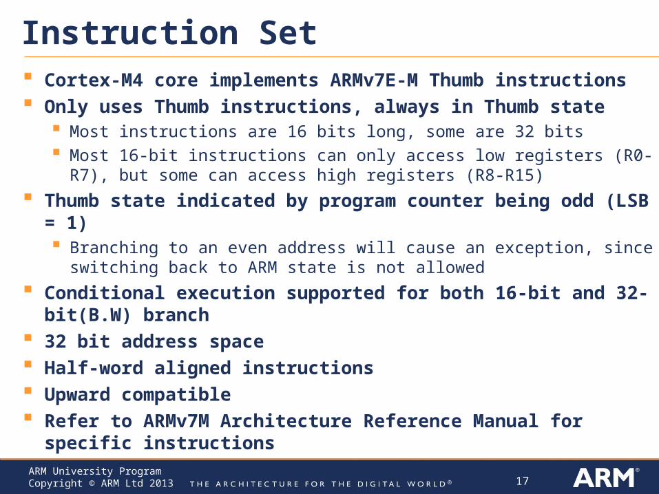
Instruction Set Cortex-M4 core implements ARMv7E-M Thumb instructions Only uses Thumb instructions, always in Thumb state
Most instructions are 16 bits long, some are 32 bits Most 16-bit instructions can only access low registers (R0-R7), but some can
access high registers (R8-R15)
Thumb state indicated by program counter being odd (LSB = 1) Branching to an even address will cause an exception, since switching back to
ARM state is not allowed
Conditional execution supported for both 16-bit and 32-bit(B.W) branch
32 bit address space Half-word aligned instructions Upward compatible Refer to ARMv7M Architecture Reference Manual for specific
instructions
18ARM University ProgramCopyright © ARM Ltd 2013
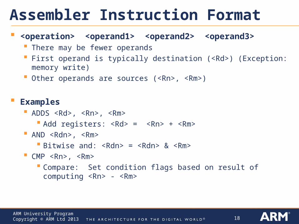
Assembler Instruction Format <operation> <operand1> <operand2> <operand3>
There may be fewer operands First operand is typically destination (<Rd>) (Exception: memory write) Other operands are sources (<Rn>, <Rm>)
Examples ADDS <Rd>, <Rn>, <Rm>
Add registers: <Rd> = <Rn> + <Rm> AND <Rdn>, <Rm>
Bitwise and: <Rdn> = <Rdn> & <Rm> CMP <Rn>, <Rm>
Compare: Set condition flags based on result of computing <Rn> - <Rm>
19ARM University ProgramCopyright © ARM Ltd 2013
Where Can the Operands Be Located? In a general-purpose register R
Destination: Rd Source: Rm, Rn Both source and destination: Rdn Target: Rt Source for shift amount: Rs
An immediate value encoded in instruction word
In a condition code flag
In memory Only for load, store, push and pop instructions
20ARM University ProgramCopyright © ARM Ltd 2013
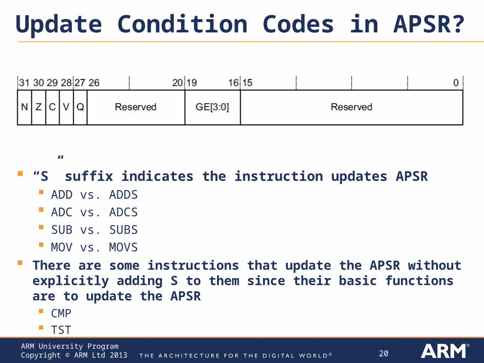
Update Condition Codes in APSR?
“S” suffix indicates the instruction updates APSR ADD vs. ADDS ADC vs. ADCS SUB vs. SUBS MOV vs. MOVS
There are some instructions that update the APSR without explicitly adding S to them since their basic functions are to update the APSR CMP TST
21ARM University ProgramCopyright © ARM Ltd 2013
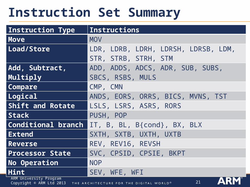
Instruction Set SummaryInstruction Type InstructionsMove MOVLoad/Store LDR, LDRB, LDRH, LDRSH, LDRSB, LDM, STR,
STRB, STRH, STMAdd, Subtract, Multiply ADD, ADDS, ADCS, ADR, SUB, SUBS, SBCS,
RSBS, MULSCompare CMP, CMNLogical ANDS, EORS, ORRS, BICS, MVNS, TSTShift and Rotate LSLS, LSRS, ASRS, RORSStack PUSH, POPConditional branch IT, B, BL, B{cond}, BX, BLXExtend SXTH, SXTB, UXTH, UXTBReverse REV, REV16, REVSHProcessor State SVC, CPSID, CPSIE, BKPTNo Operation NOPHint SEV, WFE, WFI
22ARM University ProgramCopyright © ARM Ltd 2013
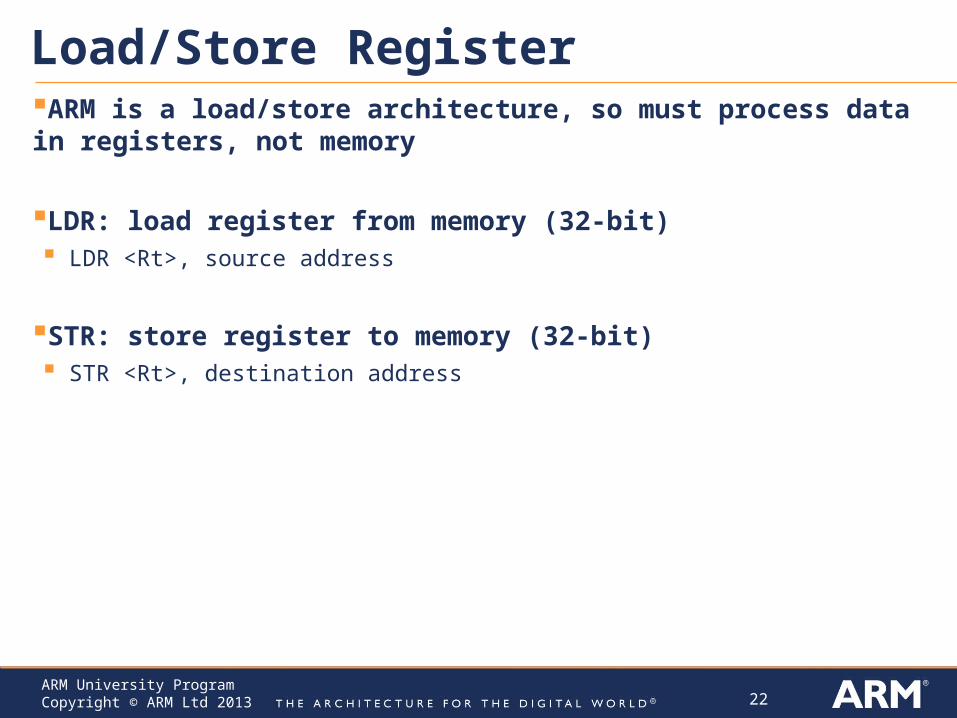
Load/Store RegisterARM is a load/store architecture, so must process data in registers, not memory
LDR: load register from memory (32-bit) LDR <Rt>, source address
STR: store register to memory (32-bit) STR <Rt>, destination address
23ARM University ProgramCopyright © ARM Ltd 2013
Addressing Memory Offset Addressing mode: [<Rn>, <offset>] accesses address
<Rn>+<offset>
Base Register <Rn>
<offset> is added or subtracted from base register to create effective address Can be an immediate constant, e.g. #0x02
Can be another register, used as index <Rm>
Auto-update(write back): Can write effective address back to base register- with an exclamation mark(!) at the back
Pre-indexing: use effective address to access memory, then update base register with that effective address
Post-indexing: use base register to access memory, then update base register with effective address
24ARM University ProgramCopyright © ARM Ltd 2013
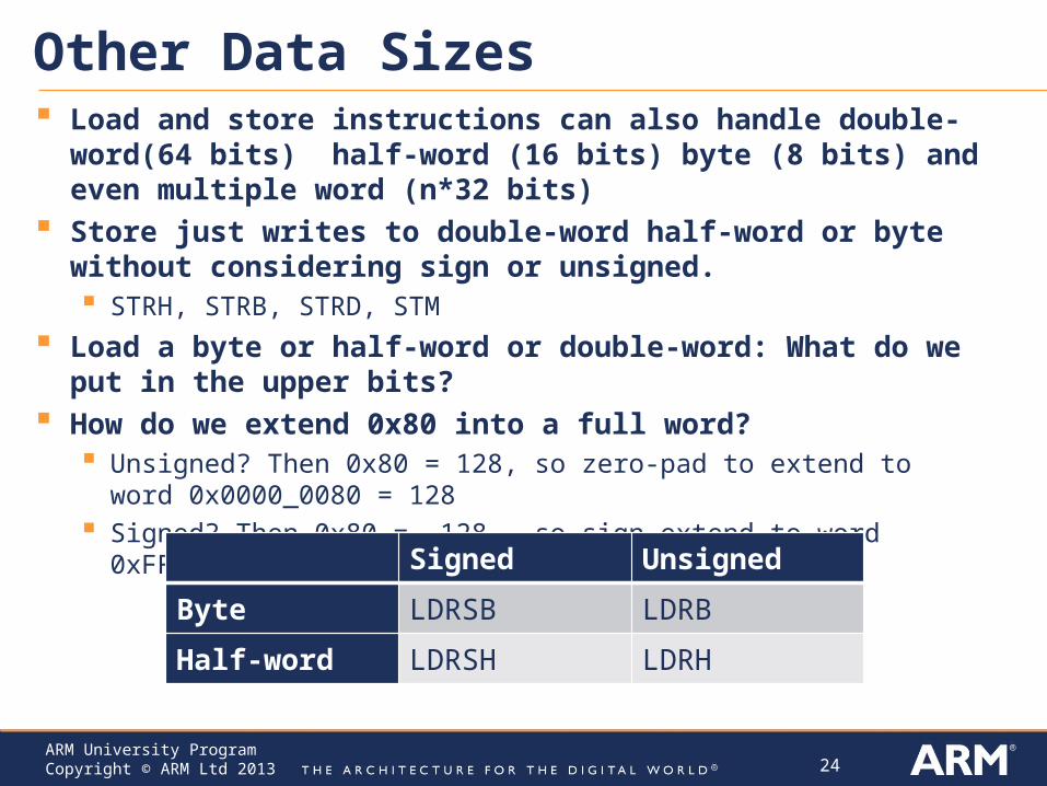
Other Data Sizes Load and store instructions can also handle double-word(64 bits)
half-word (16 bits) byte (8 bits) and even multiple word (n*32 bits) Store just writes to double-word half-word or byte without
considering sign or unsigned. STRH, STRB, STRD, STM
Load a byte or half-word or double-word: What do we put in the upper bits?
How do we extend 0x80 into a full word? Unsigned? Then 0x80 = 128, so zero-pad to extend to word 0x0000_0080
= 128 Signed? Then 0x80 = -128, so sign-extend to word 0xFFFF_FF80 = -128
Signed Unsigned
Byte LDRSB LDRB
Half-word LDRSH LDRH
25ARM University ProgramCopyright © ARM Ltd 2013
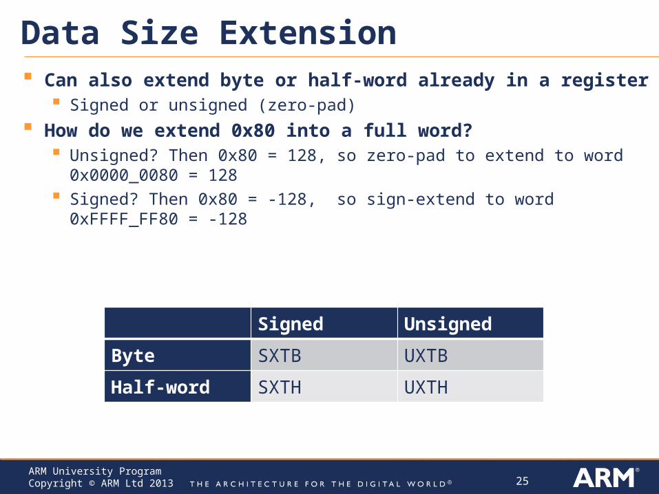
Data Size Extension Can also extend byte or half-word already in a register
Signed or unsigned (zero-pad)
How do we extend 0x80 into a full word? Unsigned? Then 0x80 = 128, so zero-pad to extend to word 0x0000_0080 = 128 Signed? Then 0x80 = -128, so sign-extend to word 0xFFFF_FF80 = -128
Signed Unsigned
Byte SXTB UXTB
Half-word SXTH UXTH
26ARM University ProgramCopyright © ARM Ltd 2013
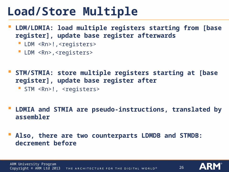
Load/Store Multiple LDM/LDMIA: load multiple registers starting from [base register],
update base register afterwards LDM <Rn>!,<registers> LDM <Rn>,<registers>
STM/STMIA: store multiple registers starting at [base register], update base register after STM <Rn>!, <registers>
LDMIA and STMIA are pseudo-instructions, translated by assembler
Also, there are two counterparts LDMDB and STMDB: decrement before

27ARM University ProgramCopyright © ARM Ltd 2013
Load Literal Value into Register Assembly instruction: LDR <rd>, =value
Assembler generates code to load <rd> with value Assembler selects best approach depending on value
Load immediate MOV instruction provides 8-bit unsigned immediate operand (0-255)
Load and shift immediate values Can use MOV, shift, rotate, sign extend instructions
Load from literal pool 1. Place value as a 32-bit literal in the program’s literal pool (table of literal values to
be loaded into registers) 2. Use instruction LDR <rd>, [pc,#offset] where offset indicates position of literal
relative to program counter value
Example formats for literal values (depends on compiler and toolchain used) Decimal: 3909 Hexadecimal: 0xa7ee Character: ‘A’ String: “44??”
28ARM University ProgramCopyright © ARM Ltd 2013
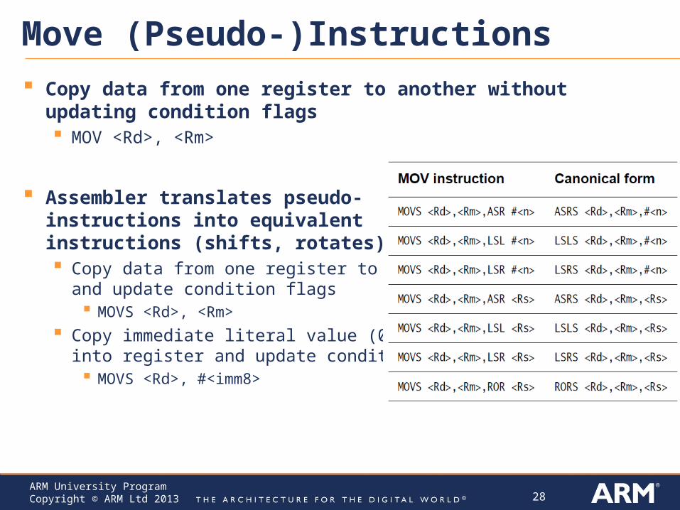
Move (Pseudo-)Instructions
Copy data from one register to another without updating condition flags MOV <Rd>, <Rm>
Assembler translates pseudo-instructions into equivalent instructions (shifts, rotates) Copy data from one register to another
and update condition flags MOVS <Rd>, <Rm>
Copy immediate literal value (0-255) into register and update condition flags MOVS <Rd>, #<imm8>
29ARM University ProgramCopyright © ARM Ltd 2013
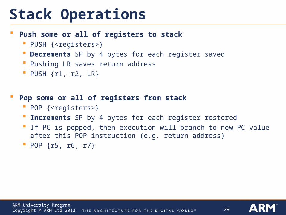
Stack Operations Push some or all of registers to stack
PUSH {<registers>} Decrements SP by 4 bytes for each register saved Pushing LR saves return address PUSH {r1, r2, LR}
Pop some or all of registers from stack POP {<registers>} Increments SP by 4 bytes for each register restored If PC is popped, then execution will branch to new PC value after this POP
instruction (e.g. return address) POP {r5, r6, r7}
30ARM University ProgramCopyright © ARM Ltd 2013
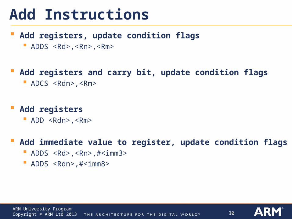
Add Instructions Add registers, update condition flags
ADDS <Rd>,<Rn>,<Rm>
Add registers and carry bit, update condition flags ADCS <Rdn>,<Rm>
Add registers ADD <Rdn>,<Rm>
Add immediate value to register, update condition flags ADDS <Rd>,<Rn>,#<imm3> ADDS <Rdn>,#<imm8>
31ARM University ProgramCopyright © ARM Ltd 2013
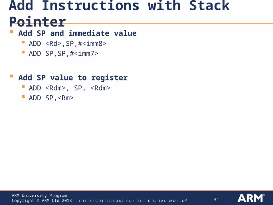
Add Instructions with Stack Pointer Add SP and immediate value
ADD <Rd>,SP,#<imm8> ADD SP,SP,#<imm7>
Add SP value to register ADD <Rdm>, SP, <Rdm> ADD SP,<Rm>
32ARM University ProgramCopyright © ARM Ltd 2013
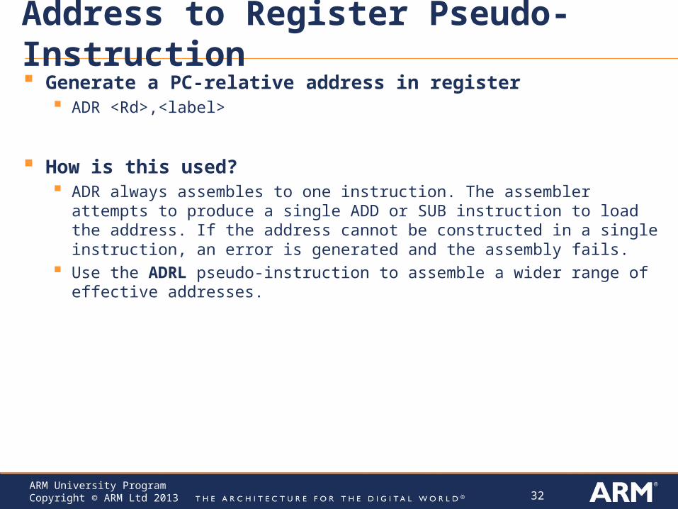
Address to Register Pseudo-Instruction Generate a PC-relative address in register
ADR <Rd>,<label>
How is this used? ADR always assembles to one instruction. The assembler attempts to produce a
single ADD or SUB instruction to load the address. If the address cannot be constructed in a single instruction, an error is generated and the assembly fails.
Use the ADRL pseudo-instruction to assemble a wider range of effective addresses.
33ARM University ProgramCopyright © ARM Ltd 2013
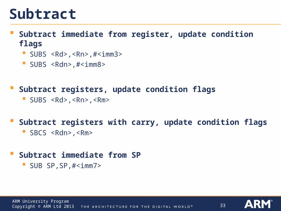
Subtract Subtract immediate from register, update condition flags
SUBS <Rd>,<Rn>,#<imm3> SUBS <Rdn>,#<imm8>
Subtract registers, update condition flags SUBS <Rd>,<Rn>,<Rm>
Subtract registers with carry, update condition flags SBCS <Rdn>,<Rm>
Subtract immediate from SP SUB SP,SP,#<imm7>
34ARM University ProgramCopyright © ARM Ltd 2013
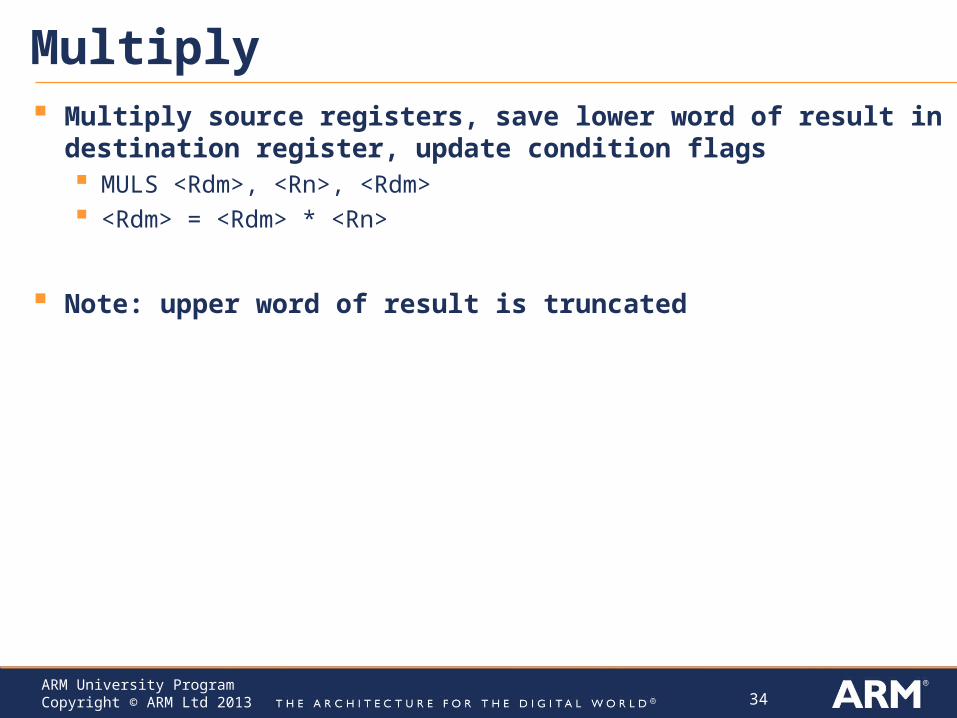
Multiply Multiply source registers, save lower word of result in destination
register, update condition flags MULS <Rdm>, <Rn>, <Rdm> <Rdm> = <Rdm> * <Rn>
Note: upper word of result is truncated
35ARM University ProgramCopyright © ARM Ltd 2013
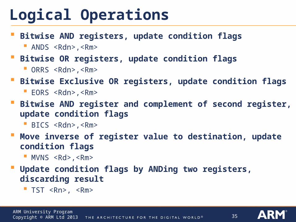
Logical Operations Bitwise AND registers, update condition flags
ANDS <Rdn>,<Rm>
Bitwise OR registers, update condition flags ORRS <Rdn>,<Rm>
Bitwise Exclusive OR registers, update condition flags EORS <Rdn>,<Rm>
Bitwise AND register and complement of second register, update condition flags BICS <Rdn>,<Rm>
Move inverse of register value to destination, update condition flags MVNS <Rd>,<Rm>
Update condition flags by ANDing two registers, discarding result TST <Rn>, <Rm>
36ARM University ProgramCopyright © ARM Ltd 2013
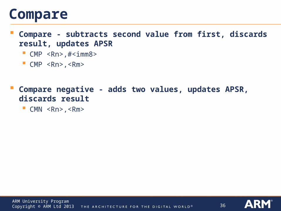
Compare Compare - subtracts second value from first, discards result, updates
APSR CMP <Rn>,#<imm8> CMP <Rn>,<Rm>
Compare negative - adds two values, updates APSR, discards result CMN <Rn>,<Rm>
37ARM University ProgramCopyright © ARM Ltd 2013
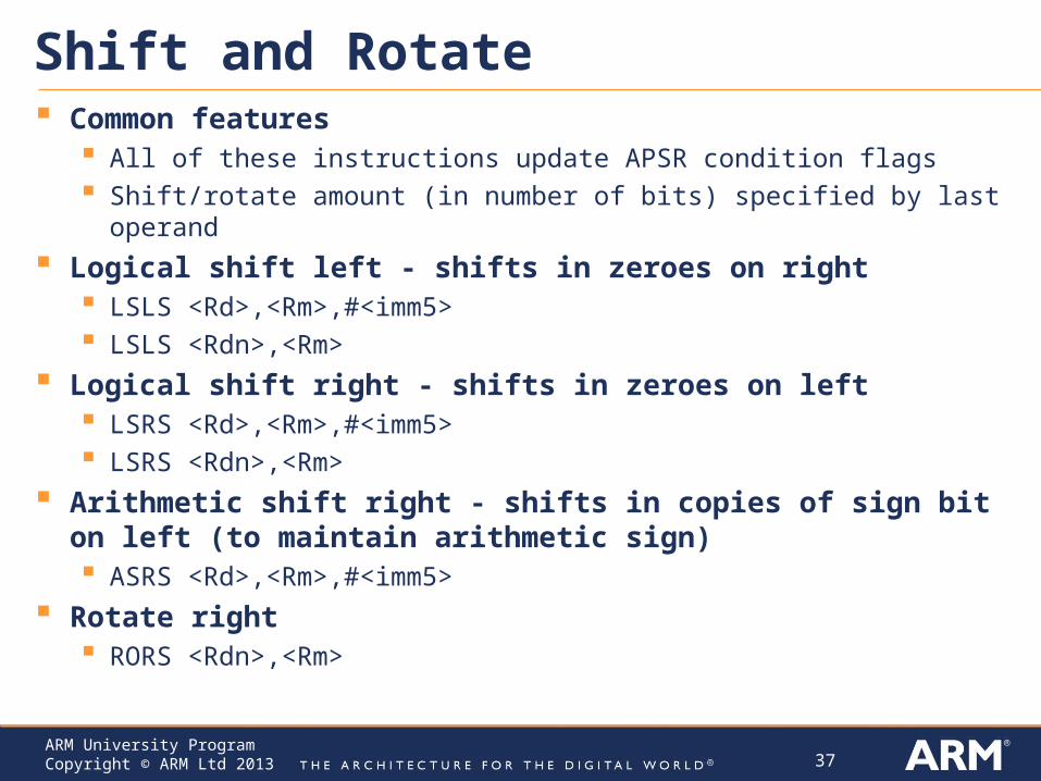
Shift and Rotate Common features
All of these instructions update APSR condition flags Shift/rotate amount (in number of bits) specified by last operand
Logical shift left - shifts in zeroes on right LSLS <Rd>,<Rm>,#<imm5> LSLS <Rdn>,<Rm>
Logical shift right - shifts in zeroes on left LSRS <Rd>,<Rm>,#<imm5> LSRS <Rdn>,<Rm>
Arithmetic shift right - shifts in copies of sign bit on left (to maintain arithmetic sign) ASRS <Rd>,<Rm>,#<imm5>
Rotate right RORS <Rdn>,<Rm>
38ARM University ProgramCopyright © ARM Ltd 2013
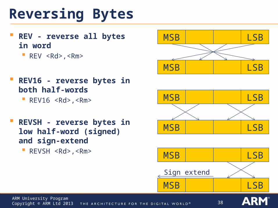
Reversing Bytes
REV - reverse all bytes in word REV <Rd>,<Rm>
REV16 - reverse bytes in both half-words REV16 <Rd>,<Rm>
REVSH - reverse bytes in low half-word (signed) and sign-extend REVSH <Rd>,<Rm>
MSB LSB
MSB LSB
MSB LSB
MSB LSB
MSB LSB
MSB LSB
Sign extend
39ARM University ProgramCopyright © ARM Ltd 2013
Changing Program Flow - Branches
Unconditional Branches B <label> Target address must be within 2 KB of branch instruction (-2048 B to
+2046 B)
Conditional Branches B<cond> <label> <cond> is condition - see next page B<cond> target address must be within 256 B of branch instruction (-
256 B to +256 B) Alternatively, can use the B.W as 32-bit version of branch instruction
for wider range.
40ARM University ProgramCopyright © ARM Ltd 2013
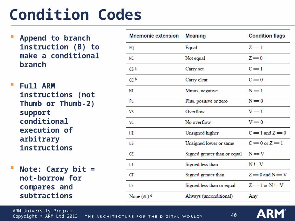
Condition Codes Append to branch
instruction (B) to make a conditional branch
Full ARM instructions (not Thumb or Thumb-2) support conditional execution of arbitrary instructions
Note: Carry bit = not-borrow for compares and subtractions
41ARM University ProgramCopyright © ARM Ltd 2013
Changing Program Flow - Subroutines Call
BL <label> - branch with link Call subroutine at <label>
PC-relative, range limited to PC+/-16MB
Save return address in LR
BLX <Rd> - branch with link and exchange Call subroutine at address in register Rd
Supports full 4GB address range
Save return address in LR
Return BX <Rd> branch and exchange
Branch to address specified by <Rd> Supports full 4 GB address space BX LR - Return from subroutine

42ARM University ProgramCopyright © ARM Ltd 2013
Special Register Instructions
Move to Register from Special Register MSR <Rd>, <spec_reg>
Move to Special Register from Register MRS <spec_reg>, <Rd>
Change Processor State - Modify PRIMASK register CPSIE - Interrupt enable CPSID - Interrupt disable
43ARM University ProgramCopyright © ARM Ltd 2013
Other No Operation - does nothing!
NOP
Breakpoint - causes hard fault or debug halt - used to implement software breakpoints BKPT #<imm8>
Wait for interrupt - Pause program, enter low-power state until a WFI wake-up event occurs (e.g. an interrupt) WFI
Supervisor call generates SVC exception (#11), same as software interrupt SVC #<imm>