zee: zero-effort crowdsourcing for indoor localization · zee: zero-effort crowdsourcing for indoor...
TRANSCRIPT
Zee: Zero-Effort Crowdsourcing for Indoor Localization
Anshul Rai†, Krishna Kant Chintalapudi†, Venkata N. Padmanabhan†, Rijurekha Sen‡∗
†Microsoft Research India ‡Indian Institute of Technology, Bombay
ABSTRACT
Radio Frequency (RF) fingerprinting, based on WiFi or cellular sig-nals, has been a popular approach to indoor localization. However,its adoption in the real world has been stymied by the need for site-specific calibration, i.e., the creation of a training data set compris-ing WiFi measurements at known locations in the space of interest.While efforts have been made to reduce this calibration effort usingmodeling, the need for measurements from known locations stillremains a bottleneck. In this paper, we present Zee – a system thatmakes the calibration zero-effort, by enabling training data to becrowdsourced without any explicit effort on the part of users.
Zee leverages the inertial sensors (e.g., accelerometer, compass,gyroscope) present in the mobile devices such as smartphones car-ried by users, to track them as they traverse an indoor environment,while simultaneously performing WiFi scans. Zee is designed torun in the background on a device without requiring any explicituser participation. The only site-specific input that Zee dependson is a map showing the pathways (e.g., hallways) and barriers(e.g., walls). A significant challenge that Zee surmounts is to trackusers without any a priori, user-specific knowledge such as theuser’s initial location, stride-length, or phone placement. Zee em-ploys a suite of novel techniques to infer location over time: (a)placement-independent step counting and orientation estimation,(b) augmented particle filtering to simultaneously estimate loca-tion and user-specific walk characteristics such as the stride length,(c) back propagation to go back and improve the accuracy of lo-calization in the past, and (d) WiFi-based particle initialization toenable faster convergence. We present an evaluation of Zee in alarge office building.
Categories and Subject Descriptors
C.2.m [Computer Systems Organization]: COMPUTER - COM-MUNICATION NETWORKS—Miscellaneous
Keywords
Indoor localization, WiFi, crowdsourcing, inertial tracking
∗The author was an intern at Microsoft Research India during thecourse of this work.
Permission to make digital or hard copies of all or part of this work forpersonal or classroom use is granted without fee provided that copies arenot made or distributed for profit or commercial advantage and that copiesbear this notice and the full citation on the first page. To copy otherwise, torepublish, to post on servers or to redistribute to lists, requires prior specificpermission and/or a fee.MobiCom’12, August 22–26, 2012, Istanbul, Turkey.Copyright 2012 ACM 978-1-4503-1159-5/12/08 ...$15.00.
1. INTRODUCTIONRF fingerprinting of WiFi signals is a popular approach to in-
door localization. Typically, there is an initial training or calibra-tion phase during which received signal strength (RSS) measure-ments from multiple WiFi access points are recorded at known lo-cations. Then, when a device is to be located, RSS measurementsfrom proximate APs are matched against the training data, eitherdeterministically [3] or probabilistically [32], to estimate location.
The need for calibration is a key bottleneck since it is labour-intensive. Further, it needs to be repeated for each new space andalso every time there is a significant change in the space (e.g., whennew APs are added or existing ones repositioned). While effortshave been made to reduce the calibration effort using RF modeling,these suffer from various limitations, including the need for at leastsome data from known locations [9], the need for control over theAPs and knowledge of their locations [11], and loss in accuracybecause measurements are made at fewer points than ideal to saveeffort. These limitations also come in the way of a crowdsourcing-based approach to training because, for instance, on a mall floor, thelocations of APs installed by multiple providers and stores wouldnot be known, and obtaining a GPS lock might not be feasible atany location.
In this paper we enable zero-effort crowdsourcing of WiFi mea-surements in indoor spaces by developing a system called Zee (namederived from the first syllable of “zero”). Our vision is of userscarrying smartphones who walk around in the indoor space of in-terest in normal course (e.g., stroll through a mall), with each usertraversing a subset of the paths in the space. We do not assumeknowledge of where within the space a user walks or even the start-ing point of the user’s walk. As well, we do not assume knowledgeof the placement of a user’s smartphone, i.e., whether it is in theirhand, shirt pocket, bag, or elsewhere, which also means that we donot know the orientation of the phone relative to the user’s direc-tion of motion. All of these elements accord well with the needsof crowdsourcing, where little can be assumed about users, and ex-plicit input or other action from users is best avoided.
The only external input that Zee depends on is a map of the in-door space of interest, which we do not view as onerous since amap would be needed anyway for the purposes of location-basedapplications such as navigation. Armed with just the map, Zeeuses WiFi and inertial sensor measurements crowdsourced from theusers’ smartphones to automatically infer location over time andthereby construct a WiFi training set (i.e., WiFi RSS measurementsannotated with location information).
The key idea behind the automatic inferencing of location in Zeeis to combine the sensor information with the constraints imposedby the map (e.g., that a user cannot walk through a wall or other bar-rier marked on the map), thereby filtering out infeasible locations
over time and converging on the true location. As an example, theinertial sensors such as accelerometer and compass might indicatethat the user walked in a zigzag path, taking a certain number ofsteps in a certain (unknown) direction, then turning 90 ◦ to the rightand continuing the walk, and finally turning 90 ◦ to the left to takea few more paces and then stopping. While the above informationdoes not, by itself, reveal location, it could when viewed togetherwith a floor map. For instance, the map might indicate that there isonly one pathway on the floor that could accommodate the kind ofzigzag trajectory observed, say the path from the entrance of a mallto a particular store. Thus, at the conclusion of the walk, we caninfer that the user’s ending location must be the store, and then wecan trace back and infer that their starting location must have beenthe entrance.
To codify the above intuition in Zee, we incorporate the un-certainty arising from sensing and the constraints imposed by themap, into a novel augmented particle filtering framework. Whereasparticle filtering in the context of localization has typically usedparticles only to represent the uncertainty in location, we createmulti-dimensional particles that also incorporate the uncertainty inother aspects such as the stride length of a user and their direc-tion of walk. Augmented particle filtering then enables the esti-mation of these latter variables concurrently with the estimation oflocation. To speed up the convergence of particle filtering, we usetwo techniques to estimate better priors for the variables being es-timated: placement-independent motion estimation to estimate thestep count and the approximate orientation (or heading offset) of adevice relative to the direction of walk, and WiFi-based initializa-
tion to leverage partial WiFi information to make an initial guess ofthe location(s) where a device might be. Finally, since the uncer-tainty in location would tend to reduce with time as a user takes alonger walk with more turns, we use backward belief propagation
to take advantage of the greater certainty in location at a later pointin time to trace back and reduce uncertainty in location at earliertimes, post facto.
Concurrently with estimating location, Zee performs WiFi scansand records the results indexed by time. As and when the locationestimate for a particular time becomes available, the correspond-ing WiFi measurement is annotated with the estimated location,thereby adding a record to the WiFi training set. Thus, Zee pro-vides a way to crowdsource WiFi measurements without requiringany explicit effort on the part of users. To evaluate the quality ofthe crowdsourced training data set, we feed it into Horus [32], awell-known WiFi fingerprinting-based localization technique, andEZ [9], a newer modeling-based technique. We find that with thecrowdsourced training data set, Horus and EZ achieve a median lo-calization error of about 3m, which is comparable to the medianlocalization error of 3.5m achieved with a training data set that isexplicitly measured.
Thus, Zee offers a truly zero-effort solution for crowdsourcingWiFi data for the purpose of indoor localization, by leveraging thewalks that users take through the space of interest in normal course.We view this as a significant contribution of our work, one thatcould be a key enabler of WiFi-based localization in real-world set-tings. As well as providing a way of constructing a training data setfor later use, another key contribution of Zee is a way to performaccurate tracking of a walking user for the purposes of real-timeapplications such as indoor navigation.
2. BACKGROUND AND RELATED WORKZee draws on prior work in multiple areas, chiefly WiFi-based
localization, robotic navigation, and inertial sensing.
2.1 Infrastructure-Based Localization SystemsEarly systems required the deployment of special-purpose infras-
tructure in the indoor space to enable localization. The inability touse GPS indoors has led to myriad approaches based on alterna-tive signals, ranging from infrared [26] to acoustic [27, 19] and vi-sual [28]. There have also been localization systems based on a de-ployment of RF transmitters and sniffers [15] or RFID [18]. Whileeach of these approaches offers certain advantages (e.g., high accu-racy in the case of acoustic ranging), the need for special-purposehardware and infrastructure is a significant challenge.
2.2 RF Fingerprinting based LocalizationLocalization based on measuring the RF signal of a wireless
LAN has the significant cost advantage of leveraging an existinginfrastructure. A popular approach, pioneered by Radar [3], is toemploy received signal strength (RSS) based fingerprinting of loca-tions in the space of interest, where typically multiple access points(APs) are heard at each location. While Radar used a simple, de-terministic fingerprinting and matching scheme, Horus [32] devel-oped a more sophisticated and accurate approach wherein the RSSmeasurements corresponding to each location and AP are repre-sented as a probability distribution and matching is performed us-ing the maximum likelihood criterion. SurroundSense [2] extendsthis idea and builds a map using several features found in typicalindoor spaces such as ambient sound, light, color, etc., in additionto WiFi RSS. Several other improvements over and extensions ofthe basic RF fingerprinting based localization have been proposed,such as the incorporation of mobility constraints [12] and an exten-sion to outdoor settings [8].
The above approaches depend on calibration of the space of in-terest to construct a training data set comprising RSS measurementsat known locations. Such calibration tends to be onerous, more sobecause it has to be repeated for every new space and each timethere is a significant change in a given space (e.g., a change in APplacement). Zee is aimed squarely at eliminating the need for suchexplicit calibration effort.
2.3 Modeling instead of CalibrationAn alternative to empirical calibration is to use an RF propaga-
tion model to estimate the RSS, Px, at a given location x basedon the the transmit power, P0, and the distance, d0x between thetransmitter and the location x. A popular model is the log-distancepath-loss model, which models the RSS (in dBm) as Px = Po −γlog(d0x) +N , where N represents a noise term [20]. Extensionsof this model have incorporated the presence of and the attenuationdue to obstructions such as walls.
Radar [3] included a model-based variant, which estimated RSSat various locations using knowledge of the AP locations and trans-mit powers, and a floor map. Radar also proposed the idea of RFenvironment profiling [4], where measurements between the (sta-tionary) access points is used to characterize the changing RF en-vironment. This idea was leveraged in [17], to develop a zero-configuration localization system, where APs make RSS measure-ments, with respect to clients and also each other. The measure-ments made between the APs are used to construct a model thatmaps RSS to distance. This model is then used locate clients throughtrilateration. This scheme, however, requires the AP software to bemodified and so cannot make use of off-the-shelf APs.
More recently, efforts have been made to use modeling with min-imal assumptions. EZ [9] only requires measurements at a fewknown client locations and WiGem [11] only requires knowledgeof AP locations and the ability to measure the client signals as re-

ceived at the APs. The reduced measurement effort with a model-ing based approach typically comes at the cost of reduced accuracy.
Zee avoids the need for measurement at any known location orany knowledge or control over AP locations and measurements.This, we believe, makes it much more amenable to a crowdsourc-ing approach because, for instance, a public space such as a mallmight have APs deployed by multiple providers and moreover theabsence of GPS coverage might make it challenging to make anymeasurements at all at known locations. Equally importantly, Zeeis able to avoid the loss of accuracy inherent in modeling based onlimited data. This is particularly relevant in the context of accuratebut measurement-intensive techniques such as Horus [32].
2.4 Alternatives to RSS-based LocalizationSeveral alternatives to RSS have also been considered. In par-
ticular, detailed physical layer information has been used to finger-print both devices [7, 5] and locations [23]. We view the contribu-tion of Zee as being orthogonal to these; the above non-RSS-basedapproaches also require a training set to be constructed and couldbenefit from the zero-effort calibration made possible by Zee.
On the other hand, there has also been research on leveragingnon-RSS information from RF beacons in a way that does not re-quire any calibration. For instance, [13] simply estimates a client’slocation as the centroid of the known locations of the APs heard,without regard to the RSS, which leads to loss in accuracy. Therehas also been work on leveraging time of flight [1] or angle ofarrival [31, 22] relative to APs, whose locations are assumed tobe known. However, these approaches either require specializedand potentially expensive hardware [1, 31] or require special hu-man effort, e.g., taking a spin while walking [22]. In Zee, weavoid these disadvantages, making our approach more amenableto crowdsourcing albeit with reduced accuracy compared to the ap-proaches based on precise measurement.
2.5 Robotic NavigationIn the robotics community, there has been much work on the
Simultaneous Localization and Mapping (SLAM) problem, whichdates from the mid-1980s [24, 16]. A robot equipped with sensors,such as laser-based ranging and cameras, is assumed to be explor-ing the space of interest, e.g., an unmapped building. The spaceis assumed to have landmarks, which are typically artificially in-serted (e.g., barcode pasted on walls or a particular pattern paintedon the ceiling). The “mapping” problem is to determine the loca-tions of the landmarks relative to each other whereas the “localiza-tion” problem is to determine the location of the robot relative tothe landmarks. Estimates are updated based on an action model,which helps relate the new location to the previous location (e.g.,based on the number of revolutions of the robot’s wheels), as wellas sensor data (e.g., visual landmarks captured by a camera sensor).
While the early work on SLAM used Kalman Filters for esti-mation, subsequent work has been based on Markov localization,which is a better match in practice since it allows the robot’s po-sition to be modeled as multi-modal and non-Gaussian probabilitydensity functions. Of particular interest to us is the Monte CarloLocalization (MCL), or particle filtering based, approach [10], whereinthe idea is to represent the belief in the robot’s location as weightedrandom samples, or particles. The particles are then evolved basedon the action model and the sensor readings.
In Zee, we build on the key idea of particle filtering by aug-menting particles to incorporate not only location but also otherunknowns such as the stride length of a particular user. However,in other respects, Zee differs from the SLAM approach. In Zee, it ishumans, not robots, that are moving around in the space of interest.
This means that we have to contend with all of the complexities as-sociated with human locomotion (e.g., measuring walking is muchmore complex than odometry based on wheel revolutions). Also,Zee does not depend on additional sensors since these are either notpresent in typical consumer devices (e.g., laser ranging) or even ifpresent are not amenable to use in a crowdsourcing setting (e.g.,users walking through a mall would not normally be taking pictureswith their smartphone camera). On the other hand, unlike SLAM,Zee assumes the availability of a map and leverages the constraintsimposed by the map for the purposes of localization.
2.6 Inertial SensingFinally, we discuss the problem of inertial sensing of human mo-
tion for the purposes of localization. This approach is interestingbecause consumer mobile devices such as smartphones are increas-ingly being equipped with sensors such as magnetometer (or com-pass), accelerometer, gyroscope, and barometer. These sensors,respectively, enable measurement of direction, acceleration, rota-tional velocity, and altitude. Knowing the starting location, a devicecan, in principle, be tracked using dead-reckoning, wherein the in-ertial sensor measurements are integrated over time [6]. However,a significant challenge is that even small errors in inertial sensingcould be magnified by integration. Zee addresses this problem byleveraging the constraints imposed by the map to filter out erro-neous measurements (e.g., a measurement that has a particle pass-ing through an obstruction such as a wall would be filtered out). Acomplementary approach to prevent the accumulation of errors isproposed in UnLoc [25], where virtual landmarks are created usingexisting sensing modalities such as WiFi.
Another significant challenge is the complexity of human loco-motion. People tend to have different stride lengths. Although therehas been work on estimating stride length based on careful model-ing of a step using accelerometer data [14], such estimation tendsto be sensitive to the placement of the sensor, as does other es-timation such as step counting. Indeed, the accelerometer signaltends to be strongest and most distinctive when the sensor is foot-mounted [21], but this does not accord with the typical placementof a device such as a smartphone. Also, in general, the device couldbe in an arbitrary orientation relative to the user’s body and their di-rection of motion, which also makes estimation challenging.
Some of the above challenges have been addressed in [29, 30].The use of map constraints for particle filtering, WiFi-based ini-tialization of particles, and augmenting the particles with orienta-tion information are all aspects inherited by Zee. In addition, thisprior work also considers transition between floors, which Zee doesnot in its present incarnation. However, the prior work assumes afoot-mounted IMU that reports step events, the stride length, andthe change in heading. These assumptions are problematic in asmartphone-based sensing context, for the reasons noted above.
To avoid assumptions regarding the placement of the IMU orprocessed step information being returned by it, we employ twotechniques in Zee. First, rather than working with sensing thresh-olds or careful modeling that tend to be placement-dependent, weleverage the fundamental, placement-independent property of walk-ing — its repetitiveness and hence periodicity — to estimate un-knowns such as the step count. Second, we augment particle filter-ing to also estimate unknowns such as the stride length based, inpart, on the constraints imposed by the map. In addition, Zee em-ploys a novel backward belief propagation technique to trace backin time and infer location information post facto, thereby enablingmore effective WiFi crowdsourcing.

Figure 1: Example Scenario
3. ZEE EXAMPLE SCENARIOAll WiFi-based indoor localization schemes require a training
data set — a set of tuples (WiFi measurement,location) of WiFiRSS measurements annotated with the indoor locations where themeasurements were made. The goal of Zee is to enable smartphone-
based crowdsourcing of this training data set without requiring any
active user participation. In fact, Zee can run as a background pro-cess on smart phones without affecting the user in any way. Inthis section, we walk through an example scenario to provide anoverview of and intuition for how Zee achieves zero-effort crowd-sourcing.Inferring a user’s location. Bob is sitting in his office at workat location A (Figure 1). He downloads the Zee client and con-tinues with his work as usual. At some point he decides to walkto Alice’s office at location D. Initially, Zee does not know whereBob is located and hence Zee initializes Bob’s locations as a prob-ability distribution uniformly across the entire floor, as depicted bythe gray region corresponding to Walk I in Figure 1). To walk toAlice’s office, Bob takes the path ABCD indicated in Figure 1.
As Bob traverses this path, Zee uses the accelerometer, com-pass and the gyroscope on Bob’s smartphone to continuously inferthe direction and distance walked by him. Then using the floor-plan of the indoor space, Zee updates the probability distribution ofBob’s location by eliminating possibilities that would require himto violate the physical constraints imposed by the floorplan, such aswalking through walls. Thus, as Bob reaches point B and then goeson to point C (as depicted in Figure 1), the spread of possible lo-cations that Bob can be at, shrinks. Eventually, when Bob reachesD, Zee is able to narrow down the possible locations of Bob to hiscorrect location. The key reason for this convergence is that thereis only one possible path in the shape of ABCD that can be accom-modate within the indoor space. Thus, even without knowing Bob’s
initial location, but by simply tracking his movements, Zee is able
to eliminate all alternative possibilities and eventually determine
his location.
Backward belief propagation. At this point, having narroweddown Bob’s location using the sequence of his movements, Zeetraces back the entire path taken by Bob and infers post facto thathe must have taken the path ABCD. Thus, Zee can also trace the
entire history of locations at which Bob was present.
Recording WiFi measurements. As Bob was traversing the pathfrom A to D, Zee was also periodically scanning for proximateWiFi Access Points (APs) and recording the Received Signal Strength(RSS) from these APs. Knowing the entire path ABCD taken byBob, Zee can associate with each RSS measurement the corre-sponding location on the path ABCD where the measurement musthave been made. Thus, Zee obtains its first set of tuples < RSS
Measurements,Locations >. Also, from this point on, havinglocated Bob, Zee can track Bob’s future movements and hence his
locations. As more WiFi measurements are made, Zee on Bob’sphone obtains more location-annotated WiFi measurements overthe rest of the day. Zee is thus is able to obtain location-annotated
WiFi measurements from Bob’s walks, without having any a priori
knowledge of his initial location.
Using past WiFi measurements to locate subsequent users. Atthis point Alice learns about Zee from Bob and installs it in herphone. She then decides to walk to Bob’s office from her officealong the path DCBA. This time, however, the Zee server has ob-tained some WiFi measurements from Bob’s walk. Thus, Zee firstperforms a WiFi scan and obtains RSS measurements from prox-imate APs. Rather than initializing Alice’s locations uniformlyacross the entire floor (as in Walk I in Figure 1), Zee uses theseRSS measurements and the database to obtain a confined proba-bility distribution, as depicted by the gray region corresponding toWalk II in Figure 1. In other words, the WiFi database obtainedfrom Bob’s walk helps Zee to narrow down the possibilities for Al-ice’s initial location. Now as Alice walks, her location estimateconverges much more quickly to her true location (by the time shereaches C in Figure 1) than it did in Bob’s case. Thus, each new
walk in Zee benefits from the WiFi measurements accumulated from
prior walks and in turn benefits the localization of future walks. In
fact, after enough walks, Zee will be able to accurately locate a
new user simply from a WiFi scan, using WiFi-based localization.
Figure 2: Zee Architecture
4. ZEE ARCHITECTUREFigure 2 depicts a pictorial overview of Zee’s architecture. There
are two key components in Zee: Placement Independent Motion
Estimator (PIME) and Augmented Particle Filter (APF). PIME usesmobile sensors such as the accelerometer, compass, and gyroscopeto estimate the user’s motion. The APF uses the motion estimatesfrom PIME and the floormap as input to track the user’s locationon the floor.Placement Independent Motion Estimator (PIME). PIME usesthe accelerometer, compass and gyroscope data to perform threekey functions. First, it reliably determines whether or not the per-son is walking. Second, when the user is walking, it generates an
event each time a step occurs and reports this event to the APF.Third, it provides APF with a rough estimate of the Heading Off-
set (HO), i.e., the angle between the orientation of the phone andthe user’s direction of motion. The heading offset arises due to thecombination of two reasons: (i) in general, the phone might notbe oriented along the direction of the user’s walk. For example,the user might be walking along the north-south direction whileholding the phone laterally, so that it points east-west, which isa common scenario when phone users watch video while walking,and (ii) the presence of magnetic materials often affects the phone’scompass. The APF then starts with the rough HO information andrefines it to arrive at an accurate HO estimate.
A key feature of PIME is that it is independent of device place-
ment, i.e., whether the user is carrying the phone in his shirt pocket,
trouser pocket, hand, etc. This is a design requirement for Zee sinceit must be able to crowdsource in the background without any activeuser participation. To achieve this, Zee includes novel techniquesfor placement independent step detection (described in Section 5)and heading offset range estimation (described in Section 6).Augmented Particle Filter. The key function of the APF is to trackthe probability distribution of a user’s location as he/she walks onthe floor. In order to convert steps into distance, the APF needsto estimate the stride length of the user, i.e., the distance traversedper step. Further, to track the user’s location, estimating the direc-tion of walking is crucial. While compass measurements providethe phone’s orientation, the APF also estimates the HO to correctlycompute the user’s direction of motion. To simultaneously esti-mate location, stride length, and heading offset, the APF takes anovel approach – it maintains a four-dimensional joint probabilitydistribution function in the form of a particle filter, comprising 2Dlocation, stride length and, HO, and learns all these values as theuser walks on the floor. The APF also implements backward-beliefpropagation, as described in Section 3.Creating the WiFi Database. The APF runs belief back-propagationto correct the user’s path history. This yields a time-indexed se-quence of the user’s estimated location during their walk. Theselocation estimates are used to annotate the time-indexed WiFi infor-mation that Zee obtains through periodic scans. Thus, Zee’s WiFidatabase comprises WiFi measurement annotated with location in-formation.WiFi-based initialization in APF. After the WiFi database hasbeen initialized using the data from the first user, for subsequentusers, APF uses information from WiFi scans and the current WiFidatabase, to obtain a confined initial location distribution, as de-scribed in Section 8. Confining the initial distribution instead ofspreading it uniformly across the floor, enables a quicker conver-gence to the actual location, as noted in Section 3.Refinement of the WiFi database. The training data obtainedfrom each subsequent walk is in turn used to refine the existingWiFi database, thus making it more accurate for the next walk. Inthis manner, both APF-based user tracking and WiFi-based local-ization work in tandem, benefitting each other and progressivelyhelping refine the WiFi database through crowdsourcing.
5. COUNTING STEPSAs described in Section 4, Zee uses step counting to estimate
the distance traversed by the user. There are two tasks for any stepcounting algorithm: first, to reliably ascertain that the user is in-deed walking, and second, to count the number of steps. Zee’s stepcounting algorithm is designed to function irrespective of deviceplacement i.e., how the device is carried by the user.Typical mobile phone placement scenarios. In order to find outhow people typically carry their phones we interviewed 30 employ-
ees in an office. Based on our interviews we found that while mostmen carry their phones in front pant pockets, some carry in theirshirt pockets or rear pant pockets and pouches attached to theirbelt. Women most often carry them in their hands or in handbagsand sometimes in pant pockets. Further, both men and women mayhold the phone in their hand while using it or to their ear while talk-ing. In designing and evaluating our schemes we used these inputsas a guide.Data collection. In order to test our schemes, six different people(four men and two women) were given smartphones to collect ac-celerometer data. Men collected data for five different placements:shirt pocket, pant front pocket, pant rear pocket, in hand while notusing the phone, and in hand while using the phone. Women col-lected data for three different placements: handbag, in hand whileusing the phone and in hand while not using the phone. For each ofthese scenarios, data was collected when the user was not walkingas well as when the user was walking.
0 0.02 0.04 0.06 0.08 0.1 0.12 0.14 0.160
0.1
0.2
0.3
0.4
0.5
0.6
0.7
0.8
0.9
11
Standard Deviation in Magnitude of Acceleration (in g)
PD
F
walking
idle
Figure 3: Distribution of standard deviation of acceleration mag-
nitudes during idle and walking states.
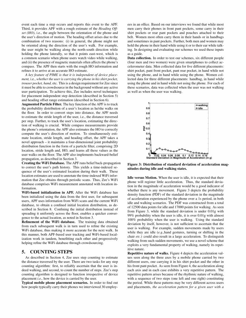
Idle versus Motion. When the user is idle, it is expected that theirphone will register little acceleration. Thus, the standard devia-tion in the magnitude of acceleration would be a good indicator ofwhether there is any movement. Figure 3 depicts the probabilitydensity function (PDF) of the standard deviation in the magnitudeof acceleration experienced by the phone over a 1s period, in bothidle and walking scenarios. The PDF was constructed from a totalof 12500 data points for idle and 17000 points for walking. As seenfrom Figure 3, while the standard deviation is under 0.01g with99% probability when the user is idle, it is over 0.01g with almost100% probability when the user is walking. Using the standarddeviation by itself, however, is not sufficient to ascertain that theuser is walking. For example, sudden movements made by userswhile they are idle (e.g.,hand gestures, turning or shifting in thechair etc.) could also result in a large acceleration. To distinguishwalking from such sudden movements, we use a novel scheme thatexploits a very fundamental property of walking, namely its repet-itive nature.Repetitive nature of walks. Figure 4 depicts the acceleration val-ues seen along the three axes by a mobile phone carried by twodifferent users, one carrying it in his shirt pocket and the other inhis front pant pocket. As seen from Figure 4, the acceleration alongeach axis and in each case exhibits a very repetitive pattern. Therepetitive pattern arises because of the rhythmic nature of walking,with a sequence of two steps (one left and one right) constitutingthe period. While these patterns may be very different across usersand placements, the acceleration pattern for a given user with a

0 50 100 150 200 250 300 350
−0.1
0
0.1
0 100 200 300−0.05
0
0.05
0.1
0 50 100 150 200 250 300 350
0.1
0.2
0 100 200 300−0.2
0
0.2
0 50 100 150 200 250 300 350−0.5
0
0.5
0 100 200 300
−0.2
0
0.2
0.4
Number of SamplesNumber of Samples
Person 1 Shirt Pocket Person 2 Front Pant Pocket
ax (g)
ay (g)
az (g)
Figure 4: Walking is repetitive
particular device placement repeats. Zee uses this observation tonot only count steps but also to ascertain that the user is indeedwalking.Normalized Auto-correlation based Step Counting (NASC). Theintuition behind NASC is that if the user is walking, then the auto-correlation will spike at the correct periodicity of the walker. Thus,given an acceleration signal a(n), Zee computes the normalizedauto-correlation for lag τ at the mth sample as,
χ (m, τ) =
Pk=τ−1
k=0
»
(a(m + k) − µ(m, τ))(a(m + k + τ) − µ(m + τ, τ))
–
τσ(m, τ)σ(m + τ, τ)(1)
In Eqn 1, µ(k, τ) and σ(k, τ) are the mean and standard deviationof the sequence of samples < a(k), a(k + 1),· · · a(k + τ − 1) >.
When the person is walking and τ is exactly equal to the periodof the acceleration pattern, the normalized auto-correlation will beclose to one. Since, the value of τ is not known a priori, NASCtries values of τ between τmin and τmax to find the value of τ forwhich χ(m, τ) becomes maximum. Thus,
ψ(m) = maxτ=τmaxτ=τmin
(χ (m, τ))) . (2)
ψ(m), the maximum normalized auto-correlation, simultaneouslyprovides two pieces of information. A high value (close to 1) sug-gests that the person is walking and the corresponding value ofτ = τopt gives the periodicity of the person’s walk.
Since the sampling frequency of our accelerometer was 50Hz,two step duration of most people lies between 40 and 100 sam-ples. Consequently, in our implementation, the initial search win-dow (τmin, τmax) is set to (40, 100). However, once the period-icity of the person’s walk is found to be τopt, the search windowis reduced to a few samples around τopt. In our implementation,after finding the user’s periodicity, we used τmin = τopt − 10 andτmax = τopt + 10. NASC continuously updates the value of τopt
to account for small changes in the user’s walking pace.Figure 5 depicts the distribution of ψ(m) for idle and walking
states. The idle state included movements such as hand gestures,transition from sitting to standing and vice versa, and spinning in achair. As seen from Figure 5, when ψ is 0.7 or higher, the probabil-ity that the person is idle is extremely low (less than 1%). Note thatNASC will also detect other repetitive activity such as running, butin this paper we did not evaluate such activities.Walk versus Idle decision in Zee To decide whether or not theuser is walking, we use a combination of both standard deviation inthe magnitude of acceleration σ||a|| and the maximum normalizedauto-correlation ψ. Zee transitions between the IDLE and WALK-ING states as follows:
−0.4−0.3−0.2−0.1 0 0.1 0.2 0.3 0.4 0.5 0.6 0.7 0.8 0.9 110
0.1
0.2
0.3
0.4
0.5
0.6
0.7
0.8
0.9
11
Maximum Normalized Auto−Correlation
PD
F
walking
idle and basic movements
Figure 5: Distribution of Maximum Normalized Auto-Correlation
during idle and walking states.
• If σ||a|| < 0.01 then state = IDLE.
• Else If ψ > 0.7 then state = WALKING.
• Else no change in current value of state.
Counting steps. Zee uses the periodicity estimated by NASC forstep counting. Having estimated τopt, NASC generates a step oc-curred event every
τopt
2samples while the person in the WALKING
state.
Hand Pant Pant Hand Shirt Hand Over
While Front Back Not Pocket
Using Pocket Pocket Using bag (all)
False 0% 0% 0% 0% 0% 0% 0%
+ive
False 2% 0% 0% 0% 0% 0% 0.6%
-ive
True 100% 100% 100% 100% 100% 100% 100%
+ive
True 98% 100% 100% 100% 100% 100% 99.4%
-ive
Table 1: Performance of step counting in Zee
Evaluation of step counting. Table 1 presents the findings fromour evaluation of step counting in Zee. A false positive means thatan extra step was counted while the user was in idle state, whilea false negative means that a step was missed while the user waswalking. Table 1 shows that these error rates are very low, oftenzero, for various placements of the phone across users.
Figure 6: Heading Offset
6. ESTIMATING HEADING OFFSET RANGETo track the user’s path, Zee must estimate the user’s direction
of walking. The mobile phone’s compass provides orientation of

the phone relative to the perceived magnetic north (i.e., the angle θin Figure 6). In general, however, the compass reading might notbe aligned with the direction of motion of the user. We refer tothis difference between the compass reading and the direction ofmotion of the user as the heading offset (HO). HO arises due to acombination of two factors: magnetic offset and placement offset.
Figure 7: Direction of North as shown by the compass across the
floor of a large office
Magnetic Offset: The presence of magnetic materials (e.g., metal)in close proximity of the mobile phone can disturb its perceptionof North, leading to an offset error in the compass measurement.We refer to this difference between the true north and the northperceived by the compass as the magnetic offset. As illustratedin Figure 6, the phone perceives north to be towards N’ while thetrue north is along N. The magnetic offset is depicted as the angleγ in Figure 6. We have found that the magnetic offset is usuallya characteristic of a given location, depending on the constructionand other materials in the vicinity, and typically remains stable withtime. Figure 7 depicts the North direction as measured by a phone’scompass at various locations on the floor of a large office building,and Figure 8 shows the distribution of magnetic offset measured at100 different locations in the floor. The magnetic offset is within±15◦ in 90% of the locations, and occasionally as high as 30◦.
−30−25−20−15−10 −5 0 5 10 15 20 25 300
.05
0.1
0.15
0.2
0.25
0.3
0.35
0.4
0.45
0.5
Magnetic Offset in Degrees
Pro
bab
ilit
y
Figure 8: Distribution of magnetic offsets
Placement offset: The phone’s compass measures the angle oforientation of the phone with respect to the perceived north. The
phone, however, might not be oriented along the direction of mo-tion of the user. For example, when the user walks while watchinga video or a photo with the phone held laterally, the orientation ofthe phone would be at an angle of 90◦ relative to the direction ofmotion of the user. We refer to this difference between the phone’sorientation and the direction of motion of the user as the place-
ment offset. In the example of Figure 6, the placement offset isdepicted by the angle α. We found that for most placements suchas in the shirt or pant pockets, the placement offset is typically ±45o. However, when the phone is placed in a pouch or a handbag,the placement offset can be arbitrary. Nevertheless, the placementoffset typically remains unchanged even when the user takes a turnand changes the direction of walking.Heading Offset: As depicted in the Figure 6, the direction of mo-tion of the user is α + θ + γ relative to the true magnetic north.In other words, the heading offset in this scenario is α + γ — thesum of the magnetic offset and the placement offset. While theplacement offset is typically constant during a single walk (unlessthe user changes how he/she is carrying the phone in the middleof the walk), the magnetic offset can change as the user movesthrough different locations. Consequently, Zee must accommodateboth these components of the HO. To estimate HO, Zee takes atwo-step approach. It first estimates the HO in a broad range (sec-tor) based on the acceleration experienced by the phone. Then, theAPF uses this range of values as the prior for the HO distributionand proceeds to refine its estimate of the HO as the user walks. Inthe remainder of this section, we describe our technique for esti-mating the HO range; we defer discussion of the APF to Section 7.
0 1 2 3 40
5
10
15
Ma
gn
itu
de
0 1 2 3 40
5
10
15
0 1 2 3 40
20
40
60
Frequency (Hz)
Ma
gn
itu
de
0 1 2 3 40
20
40
60
Frequency (Hz)
(0.98 Hz)
(0.88 Hz)(2.64 Hz)
(1.76 Hz)
(2.64 Hz)
(3.52 Hz)
(1.96 Hz)
(2.94 Hz)(0.98 Hz)
Perpendicular to Motion
Perpendicular to Motion
Parallel to Motion
Parallel to Motion
Person 1 Pant Front Pocket
Person 2 Shirt Pocket
Figure 9: Spectrum of walking
The spectrum of a typical walk. Figure 9 depicts the magnitude ofthe Fourier transform of the accelerometer signal registered by thephone along directions parallel and perpendicular to the directionof walking, for two different people. Person 1 carries the phonein his shirt pocket while person 2 carries the phone in his frontpant pocket. As seen in Figure 9, the dominant frequencies aremultiples (harmonics) of a fundamental frequency. For example, inthe case of person 1, the fundamental frequency is 0.88 Hz whilefor the second person it is 0.98 Hz. This fundamental frequency

corresponds to the periodicity of two steps, i.e., the combination ofa left step and a right step.
After observing the Fourier transform across several users andplacements, we discovered an interesting fact: the second harmonic
(two times the fundamental frequency, corresponding to the peri-
odicity of single steps) is either completely absent or is extremely
weak in the accelerations experienced by the phone in the direction
perpendicular to the user’s walk. It is however always present and
dominant in the direction parallel to the user’s walk. This rather cu-rious phenomenon arises for the following reason. In the directionparallel to the walk, each step (left or right) registers as a strong,repetitive acceleration signal. However, this is not so in the perpen-dicular direction, because the user’s sideways or lateral movement(e.g., hip sway) only repeats every two steps. Indeed, as can be seenin Figure 9, the second harmonic frequencies corresponding to 1.76Hz (person 1) and 1.96 Hz (person 2), while being present in thedirection parallel to the user’s walk, are absent in the perpendiculardirection.Heading Offset (HO) range estimation. Suppose the magnitudeof the second harmonic in the Fourier transform along north is Fy
and that along west is Fx. Almost the entire contribution to thisharmonic is from the direction of walking, so Fx and Fy must beits components. Thus, α + θ + γ = arctan Fx
Fy(Figure 6). How-
ever, since we work with the (unsigned) magnitude of the Fouriertransform, we cannot tell whether the person is walking forward orbackward along this angle. Consequently, it is equally likely thatα + θ + γ = arctan Fx
Fy+ 180o. Knowing θ from the compass
then, the two possible values of α+ γ (HO) can be estimated.
−50 0 50 100 150 200 2500
0.02
0.04
0.06
0.08
0.1
0.12
0.14
0.16
0.18
0.2
Estimation Error (Degrees)
Pro
ba
bil
ity
Figure 10: Error distribution of HO estimation
We characterize the error in our HO estimation scheme by test-ing it on the same walk data collected across six different people,as in Section 5. Figure 10 depicts the probability distribution ofthe error in the HO estimation. The distribution is bimodal around0◦ and 180◦, because, as noted above, the HO estimation schemecannot distinguish between the forward and backward directions.Further, the error spans about 60◦ around each of 0◦ and 180◦.Thus, the error in our HO estimation is large and by itself cannotbe used to track the user. Nevertheless, it helps narrow down thepossibilities to two diametrically opposite 90◦ sectors (expandedfrom 60◦ to accommodated the possibility of larger errors) centeredabout arctan Fx
Fy. The APF then uses this estimate as the prior to
efficiently converge on the correct HO, as discussed next.
7. TRACKING USING AUGMENTED PAR-
TICLE FILTER (APF)In this section we describe how Zee uses APF to track the users’
paths as they walk around in an indoor environment.The key idea. The key idea of Zee is that as a user continues to
walk in an indoor environment, navigating through hallways and
turning around corners, the possibilities for the user’s path and lo-
cation shrink progressively. For example, if a person walks 10mnorth followed by 12m east and then 20m south in an indoor spacewith hallways and walls, there will likely be only a few paths inthe indoor environment that could accommodate such a walk with-out having the user run into a wall or other barrier. The longer thewalk, the more concentrated the possibilities. As a user walks inthe indoor environment while going about their routine, Zee con-tinually eliminates possibilities that violate wall constraints, untileventually only one possibility remains. To drive towards suchconvergence, Zee maintains a probability distribution of possiblelocations of the user and updates it for every step taken by the user.
Zee uses the stride length to convert each step into the corre-sponding distance traversed. However, people generally have dif-ferent stride lengths, because of differences in height and walkingstyle, so Zee must estimate the stride length of each user, while si-multaneously attempting to locate them. Further, as described inSection 6, Zee must also estimate the HO accurately. To accom-plish these tasks, Zee augments the standard particle filter to in-clude not only of the location of the user but also the stride lengthand the HO as two additional unknowns. Thus, Zee continuouslymaintains and updates a four-dimensional joint probability distri-bution over the 2D location, stride length, and HO of the user.
Figure 13: Stride estimation in Zee
Example of stride length estimation. For intuition on how stridelength estimation works, consider a simple example, where theuser’s initial location is assumed to be known but not their stridelength. Initially, Zee considers the full range of humanly feasiblestride lengths (0.5m to 1.2m, in our current implementation). Theuser’s initial location is shown in Figure 13 as the particle concen-tration (gray region) labeled A. As the user takes steps and moves toB and then onto C, the gray region becomes elongated. The reasonis that since Zee consider a range of possible stride lengths, parti-cles corresponding to a longer stride length travel farther than thosewith a shorter stride length. At point D, when the user takes a rightturn into a passage way, particles with stride lengths that are eithertoo large or too short attempt to move to the right but are hinderedby the walls on either side of the passage way. Consequently, asthe user walks into the passage way, the possibilities for the user’sstride length narrow down. The more the user walks and navigatesaround corners, the more accurate the estimate becomes. While inthis simple example we assumed that the initial location is known,even if the initial location were unknown, Zee can estimate locationand stride length simultaneously as the user continues to walk.
In practice, we found that within a single walk, users exhibit up

Figure 11: An example run of Zee
Figure 12: Backward belief propagation in Zee
to ±10% variation in their stride length. To account for this varia-tion, we add a random error δ uniformly distributed in the range of± 10% of the stride length (used in Equation 3 below).Working with heading offset. Zee estimates the HO in a similarmanner as it estimates the stride length. Initially, the heading offsetis uniformly distributed within the two 90◦ sectors suggested by theHO range estimation scheme in Section 6. As the user walks, in-correct HO values are eliminated due to the wall constraints. Whilethis approach accounts for the errors in the constant component ofHO (due to phone placement), the APF must also account for thechanges in HO due to different magnetic offsets at different loca-tions. In order to accommodate this variation, the APF models thiscomponent as a compass measurement error — a Gaussian randomvariable β that is added to the compass measurement (used in Equa-tion 3 below). We found that using a zero mean Gaussian with astandard deviation of 5◦ typically was sufficient in our floor.The particle filter. The APF maintains a four-dimensional jointprobability distribution as a particle filter, with a set of particles(samples), X = (X1,X2· · · ,XN ) representing the probability dis-tribution. Here Xi = (xi, yi, si, αi), with (xi, yi) being the 2Dlocation, si the stride length, and αi the placement offset. After theuser takes the kth step, the ith particle is updated as,
xki = x
k−1
i + (si + δi) cos(αi + θ + βi) (3)
yki = y
k−1
i + (si + δi) sin(αi + θ + βi) (4)
As noted earlier, si is perturbed by δi to account for variation in thestride length, and θ (the compass reading) is perturbed by βi to ac-count for compass measurement error and variation in the magneticoffset.
After each update, particles are tested to see if they violate anywall constraints. If the line joining (xk−1
i , yk−1
i ) and (xki , y
ki ) in-
tersects a wall then the particle is eliminated. In order to replace
each eliminated particle, a new particle is randomly chosen fromthe particle set at the k − 1th step and updated. Note that si and αi
are not updated, rather incorrect values only get eliminated.In our implementation we found that within one step, often it
is possible to sample the compass several times. Accordingly, weuse an average value of all the samples to arrive at the θ for thestep. Sometimes, however, when the user turns, θ might changeby a large amount within one step. Consequently, if the compassreading changes by more than 20◦ within a single step, we per-form incremental updates by subdividing the step into fractionalsub-steps.An example walk in an office building. Figure 11 shows howZee works in a large office floor, measuring 65m × 35m. The userwas asked to walk from O to D, along the path shown in Figure 11.There are three turns in the path, at points A, B and C. Initially,particles were instantiated at all possible locations with all possi-ble stride lengths and heading offsets spread uniformly over thetwo 90◦ sectors suggested by the HO range estimator. As the userwalks to point A and then turns, the spread of particles dramati-cally decreases, as several possibilities are eliminated. Further, asthe user walks towards point B, even more possibilities are elimi-nated. Finally, as the user navigates around the turn at B, Zee hasnarrowed down to the user’s correct location.Backward belief propagation. After the turn taken at B, the po-sition of the user is localized to a single concentration of particles.Tracing these particles back in time would, therefore, allow us toinfer the past locations of the user accurately. To enable such atrace-back, each particle X
ki after the kth step maintains a link to
its parent particle, i.e., the particle Xk−1
j that it was generated from.In the backward belief propagation step, out of the set of particlesX
k−1 = {Xk−1
1,Xk−1
2,· · · ,Xk−1
N }, the particles with no children
surviving in the succeeding step (i.e., in the set Xk), are elimi-
nated. This helps ensure that possibilities that are filtered out in

future steps are not retained in the past steps. Figure 12 depictsthe results of applying backward belief propagation on the user’swalk along the reverse direction, starting from after the turn at Band going back to the initial location O. As the figure shows, us-ing backward belief propagation, Zee is able to accurately trace theuser’s path back to the starting location O.
8. PUTTING IT ALL TOGETHER: ZERO-
EFFORT CROWDSOURCINGZee periodically scans for beacons from proximate WiFi Access
Points (AP) and records the Received Signal Strength (RSS) mea-sured, along with a timestamp. Also, as Zee tracks the path taken byusers, whether in the forward direction or through backward beliefpropagation, it annotates the path with timestamps, indicating thetimes at which the user was located at particular points in the path.Thus, Zee can determine where in the floor a certain WiFi mea-surement was taken and thereby generate location-annotated WiFimeasurements of the form (location, WiFi RSS). This database ofmeasurements can then be used to locate new users using existingWiFi localization techniques. We now describe the two WiFi local-ization schemes used in our evaluation.HORUS. HORUS uses a set of location-annotated RSS measure-ments to construct a probability distribution, P (rssAPk
= r|x =xi), i.e., the probability of measuring an RSS value of r from ac-cess point APk at location xi. x here is a 2-dimensional location.In order to locate a device using HORUS, a device measures a vec-tor of RSS measurements, R = < r1,r2,· · · ,rm >, where ri isthe RSS from APi. The probability of observing R at a locationxi is then computed as,
P (R|x = xi) =Y
k
P (rssAP k= rk|x = xi) (5)
Using Bayesian inference, HORUS computes P (x = xi|R). Thelocation of the device is then estimated as either the maximum like-
lihood location (i.e., the location with the highest probability) orthe expectation over all locations (expected location).EZ. EZ relies on a widely-used RF propagation model for WiFireceived signal strength (RSS) in indoor environments — the LogDistance Path Loss (LDPL) model. The LDPL model estimatesRSS rssk
x(in dBm) measured at a location x of the signal from
APk placed at a location ck as,
rsskx
= rssk0 − 10γk log (d (x, ck)) +N(x). (6)
In Eqn 6, rssk0 is the RSS from APk at the reference distance of
1m, γk is the path loss exponent, and d(x, ck) is the distance be-tween locations x and ck. N(x) captures the random fluctuationsin RSS due to multi-path effects. EZ uses WiFi measurements (afew annotated with location information but most not) from withinthe indoor space data to construct the LDPL model for each WiFiAP. Then, to locate a device, it converts the RSS measurement ob-tained from an AP to the estimated distance from that AP using,
d(x, ck) = 10
rssk0−rk
10γ
!
. (7)
Standard trilateration is then used to locate the device, once its dis-tance from three or more APs has been estimated.Using existing measurement database for subsequent crowd-
sourcing. In the absence of prior information, Zee starts by spread-ing the probability distribution of a user’s location across the floor.However, once “enough” location-annotated WiFi measurementshave been gathered, Zee can use existing localization schemes suchas HORUS or EZ to initialize the probability distribution in a more
localized area rather than over the entire floor. When using HO-RUS, Zee draws random samples from P (x = xi|R) and initial-izes the locations of the particles accordingly. When using EZ, Zeeperturbs the measured RSS values to simulate the effect of mul-tipath (using a Gaussian distribution with mean 0dB and standarddeviation 5dB) and then generates sample locations for the parti-cle filter. Using such a localized distribution rather than one spreadacross the entire floor helps speed up the convergence of the parti-cle filter, thereby aiding subsequent crowdsourcing.Dealing With Paths With Unconverged Particles. Not all pathsmay lead to a unique location in Zee, e.g., short paths that do notinclude enough turns to uniquely establish the user’s trajectory. Insuch cases, the spread of particles will typically be large instead ofbeing confined to a small region. Zee identifies such unconvergedpaths using measures such as the variance in the locations of parti-cles and the number well-separated clusters, and discards the WiFimeasurements corresponding to such walks.
9. EVALUATIONWe evaluate the performance of Zee in a large office building,
with a 65m × 35m floor plan, as depicted in Figure 14. We seekto answer several questions, including: (a) how well is Zee able totrack users, (b) if Zee had been provided the user’s initial locationor had accurate knowledge of the heading offset, would its perfor-mance have improved significantly, (c) how well does Zee estimatequantities such as the stride length and the heading offset of theuser, and (d) how well do existing localization schemes performwhen using the location-annotated data generated by Zee versususing manually collected data.
Experimental methodology. In a real-world setting, we expectseveral users to be running the Zee client on their phone as theywalk through various sections of an indoor space. Further, usersare unlikely to be walking continuously; they would typically walkbetween locations of interest and dwell at certain locations (e.g., astore) for a significant length of time. However, for our evaluation,we did not have the luxury of several users. Instead, we handed aphone running the Zee client to a user, who kept it with himself forabout 15 hours continuously. Our experiment included elementsaimed at emulating the real-world characteristics noted above.
To recreate walks with breaks at various locations, the user wasasked to walk to various parts of the office floor whenever he hadthe time and leave the phone there for periods ranging from 20 min-utes to a half-hour. Zee was left running on the phone continuously.Upon detecting no walking activity for more than 10 seconds, theaccelerometer data was not processed until walking was detectedagain. WiFi data, however, is more valuable when collected from asingle location over an extended period, since it helps capture thevariability in the WiFi signal at that location. Consequently, WiFiRSS measurements were collected even during the time when thedevice was stationary. To record the ground truth for location, theuser made note of the locations on a map where he had stopped andthe corresponding time periods.
In order to evaluate the benefit of using data from previous usersfor subsequent data collection, the user in our experiment stoppedZee briefly, walked over to a completely different location on thefloor, and then restarted Zee. In this manner four different “walks”were created by restarting Zee four times. Each time, Zee wouldinitialize the user’s location based on the WiFi data gathered fromthe previous walks.
Figure 14 shows the paths covered by the user during the 15-hourperiod (shown as the dark lines in the figure). Several of the loca-tions were visited multiple times over the course of the experiment.Zee’s tracking performance. We first show the performance of

Figure 14: Total area covered during the 15
hrs by the user
0 20 40 60 80 100 120 140 160 180 2000
5
10
15
20
25
30
35
40
No of Steps
Lo
calizati
on
Err
or
(m)
Zee
Zee + HO
Zee + HO, Initial Location
Figure 15: Location errors seen by Zee dur-
ing walk 1.
0 20 40 60 80 100 120 140 160 180−0.1
−0.05
0
0.05
0.1
0.15
0.2
0.25
No of Steps
Str
ide L
en
gth
Err
or
in m
Zee
Zee + HO
Zee + HO, Initial Location
Figure 16: Stride length errors seen by Zee
during walk 1.
0 20 40 60 80 100 120 140 160 1800
0.5
1
1.5
2
2.5
No of Steps
Lo
calizati
on
Err
or
in m
Zee
Zee + HO
Zee + HO, Initial Loc
Figure 17: Location errors seen after back-
ward belief propagation by Zee during walk
1
0 25 50 75 100 125 150 175 200 225 2500
5
10
15
20
25
30
35
40
No of steps
Lo
cati
on
Err
or
in m
walk1
walk2 (data from walk1)
walk3 (data from walk2)
walk4 (data from walk3)
Figure 18: Using WiFi measurements from
previous walks to start subsequent walks
0 5 10 15 20 25 30 35 40 45 500
0.1
0.2
0.3
0.4
0.5
0.6
0.7
0.8
0.9
11
Localization Error in m
CD
F
Horus
EZ
ZeeHorus − Path Only
ZeeEZ − Path Only
ZeeEZ
ZeeHorus
Figure 19: Performance of WiFi localiza-
tion on Zee data
Zee on the first walk when there was no prior data from the floor.Note that this was not a continuous walk but instead was punctuatedby several long stops, each lasting 20-30 minutes, as the user wentto different locations on the floor. The walk lasted a total of 3 hours.Figure 15 depicts the location error seen by the particle filter at9 different checkpoints (i.e., predetermined locations, where theground truth was recorded) as a function of the step count duringthe walk. The location error was computed by estimating the user’slocation as the average location over all surviving particles, andthen finding its distance from the ground truth location.
Figure 15 shows the location error with the particle filter runin the forward direction. As can be seen from the curve labeledZee, initially the average error is extremely high. This is becausethe initial location is unknown and particles are spread all acrossthe floor. Somewhere between steps 80 and 100, the user took aturn that eliminated all spurious possibilities and the error droppedsharply. At the end of the walk, the location error was under ameter; in other words, Zee’s location estimate was correct to thelast step!
Figure 17 depicts the location error after backward belief propa-gation was applied to the walk. As can be seen from the figure, thelocation error along the entire path is under 2m after this step.Zee’s performance with initial location and HO being known.
In this experiment, we tested two different scenarios. In the firstscenario, the initial location of the user was kept as unknown whileheading offset was treated as known. In the second scenario, both
heading offset and initial location were treated as known. Stridelength, however, was assumed to be unknown in both cases.
As seen from Figure 15, with the HO known but initial locationunknown, Zee converged must faster to the correct location com-pared to not knowing the HO, which is as expected. When bothHO and initial location were known, initially the error increasedbecause the stride length was unknown. However, as soon as Zeelearned the stride length, the localization error reduced.
Figure 17 depicts the localization error for both these scenariosafter backward belief propagation is applied. As seen from the fig-ure, the location error along the entire path remains under 1m inboth the scenarios. Further, the key point to note here is that Zee
was able to perform similarly well despite not knowing HO and ini-
tial location as when this information was known a priori, the only
difference being that it took longer to converge in the former case,
which is as expected.
Zee’s estimation of stride length. To evaluate how well Zee es-timates stride length, we first measured the user’s stride length bymaking him walk 20 steps in a straight line and directly measur-ing the distance covered. Then, during the actual experiment, weestimated the stride length at any step as the average stride lengthover the surviving particles. Figure 16 shows that the error in stridelength estimation drops to around 5cm by the end of the walk.Using WiFi measurements from previous walks for subsequent
walks. For each successive walk, Zee was able to use the WiFidata gathered from the prior walks to estimate the distribution ofthe user’s starting location. To compute this distribution, we used

EZ, as described in Section 8. To emulate a new user for eachwalk, the stride length and HO were deemed as being unknown atthe beginning of each successive walk. Figure 18 shows that byusing WiFi information from prior walks, Zee is able to convergemuch faster and have smaller location errors than otherwise.Performance of WiFi localization using Zee-based crowdsourc-
ing. To evaluate the performance of existing WiFi-based localiza-tion schemes when fed with Zee-based crowdsourced data, we firstset up the baseline by collecting WiFi measurements manually at117 locations, spaced about 3m apart and spread across the floor.At each location approximately 1000 WiFi beacons were collectedfor each proximate AP. This data was used to train HORUS andEZ. Additionally, we collected data from 91 separate test locationsspread across the entire floor. Figure 19 depicts the distribution oflocalization error seen by EZ and HORUS at these test locations(labeled as EZ and HORUS in the figure).
Next, instead of the data gathered manually, we used the dataobtained from Zee over the four walks to train EZ and HORUS,and tested these across all the 91 test locations. The correspond-ing distributions of localization error are also shown in Figure 19(labeled as ZeeEZ and ZeeHORUS). We see that while ZeeEZ andZeeHORUS have almost the same 50%ile errors as EZ and HO-RUS, respectively, the 80%ile errors are significantly larger. Thiswas because, at the test locations that were far from all of the walkpaths (which defined the spatial extent of crowdsourcing in this ex-periment), ZeeEZ and ZeeHORUS performed much worse than EZand HORUS (which had the benefit of manually-gathered trainingdata from across the floor).
To evaluate the performance of Zee more fairly, we tested Zeeonly on the test locations that were within 5m of any of the fourwalk paths. Figure 19 depicts the corresponding error distributions(labeled as ZeeEZ Path Only and ZeeHORUS Path Only). We seethat the 50%ile and 80%ile errors are 1.2m and 2.3m, respectively,which are comparable to those seen when manually-gathered datais used for training (the curves labeled EZ and HORUS). This en-couraging result suggests that Zee-based crowdsourcing could beeffective and could enable localization with high accuracy, pro-vided the space is well-covered by users during the course of theircrowdsourcing walks.
10. CONCLUSIONIn this paper, we have presented Zee, a system that enables crowd-
sourcing of location-annotated WiFi measurements in indoor spaces,using the mobile phones carried by users in normal course. A keyattribute of crowdsourcing with Zee is that it is “zero-effort”, notrequiring any active user intervention in terms of location input,placement of the phone, or other aspect. Zee employs a set of noveltechniques to resolve ambiguity in location during crowdsourcing,using inertial and WiFi measurements, and a map of the indoorspace as the inputs. The data thus gathered can help train exist-ing WiFi-based localization algorithms. Our evaluation on a largeoffice floor shows that existing WiFi-based localization schemes,both fingerprinting-based and modeling-based, are able to performaccurate localization when trained with data that is crowdsourcedautomatically using Zee.
11. ACKNOWLEDGEMENTSWe thank Gursharan Sidhu for suggesting that WiFi data could
be crowdsourced with the help of inertial tracking. We also thankour shepherd, Romit Roy Choudhury, and the anonymous review-ers for their constructive comments.
12. REFERENCES
[1] Time Domain. http://www.timedomain.com/.
[2] M. Azizyan, I. Constandache, and R. Roy Choudhury. SurroundSense: MobilePhone Localization via Ambience Fingerprinting. In MobiCom, 2009.
[3] P. Bahl and V. N. Padmanabhan. RADAR: An Inbuilding RF-based UserLocation and Tracking System. In INFOCOM, 2000.
[4] P. Bahl, V. N. Padmanabhan, and A. Balachandran. Enhancements to theRADAR User Location and Tracking System, Feb 2000. Microsoft ResearchTechnical Report MSR-TR-2000-12.
[5] K. Bauer, D. Mccoy, B. Greenstein, D. Grunwald, and D. Sicker. Using WirelessPhysical Layer Information to Construct Implicit Identifiers. In HotPETs, 2008.
[6] S. Beauregard and H. Haas. Pedestrian Dead Reckoning: A Basis for PersonalPositioning. In WPNC, 2006.
[7] V. Brik, S. Banerjee, M. Gruteser, and S. Oh. Wireless Device Identificationwith Radiometric Signatures. In Mobicom, 2008.
[8] Y.-C. Cheng, Y. Chawathe, A. LaMarca, and J. Krumm. AccuracyCharacterization for Metropolitan-scaleWi-Fi Localization. In MobiSys, 2005.
[9] K. Chintalapudi, A. P. Iyer, and V. N. Padmanabhan. Indoor LocalizationWithout the Pain. In Mobicom, 2010.
[10] D. Fox, W. Burgard, F. Dellaert, and S. Thrun. Monte Carlo Localization:Efficient Position Estimation for Mobile Robots. In AAAI, 1999.
[11] A. Goswami, L. E. Ortiz, and S. R. Das. WiGEM : A Learning-Based Approachfor Indoor Localization. In CoNEXT, 2011.
[12] A. Haeberlen, E. Flannery, A. M. Ladd, A. Rudys, D. S. Wallach, and L. E.Kavraki. Practical Robust Localization over Large-Scale 802.11 WirelessNetworks. In MobiCom, 2004.
[13] N. B. John, J. Heidemann, and D. Estrin. GPS-Less Low Cost OutdoorLocalization For Very Small Devices. IEEE Personal Communications
Magazine, 7:28–34, 2000.
[14] J. W. Kim, H. J. Jang, D.-H. Hwang, and C. Park. A step, stride and headingdetermination for the pedestrian navigation system. Journal of Global
Positioning Systems, 3:273–276, 2004.
[15] P. Krishnan, A. S. Krishnakumar, W. H. Ju, C. Mallows, and S. Ganu. A Systemfor LEASE: Location Estimation Assisted by Stationery Emitters for Indoor RFWireless Networks. In Infocom, 2004.
[16] J. Leonard and H. F. Durrant-whyte. Simultanoues Map Building andLocalization for an Autonomous Mobile Robot. In IROS, pages 1442–1447,1991.
[17] H. Lim, L. Kung, J. Hou, and H. Luo. Zero-Configuration, Robust IndoorLocalization: Theory and Experimentation. In Infocom, 2006.
[18] L. Ni, Y. Liu, C. Yiu, and A. Patil. LANDMARC: Indoor Location SensingUsing Active RFID. In WINET, 2004.
[19] N. B. Priyantha, A. Chakraborty, and H. Balakrishnan. The CricketLocation-Support System. In MobiCom, 2000.
[20] T. Rappaport. Wireless Communications Principles and Practice. Prentice Hall,2001.
[21] P. Robertson, M. Angermann, and B. Krach. Simultaneous Localization andMapping for Pedestrians using only Foot-Mounted Inertial Sensors. InUbicomp, 2009.
[22] S. Sen, R. R. Choudhury, and S. Nelakuditi. SpinLoc: Spin once to know yourlocation. In ACM HotMobile, 2012.
[23] S. Sen, B. Radunovic, R. R. Choudhury, and T. Minka. Precise IndoorLocalization using PHY Layer Information. In ACM HotNets, 2011.
[24] R. Smith and P. Cheeseman. On the Respresentation and Estimation of SpatialUncertainty. The International Journal of Robotics Research, 5, Winter 1986.
[25] H. Wang, S. Sen, A. Elgohary, M. Farid, M. Youssef, and R. R. Choudhury. NoNeed to War-Drive: Unsupervised Indoor Localization. In Mobisys, 2012.
[26] R. Want and et al. The Active Badge Location System. ACM Transactions on
Information Systems, Jan 1992.
[27] A. Ward, A. Jones, and A. Hopper. A New Location Technique for the ActiveOffice. IEEE Per. Comm., 4(5):42–47, 1997.
[28] A. Williams, D. Ganesan, and A. Hanson. Aging in Place: Fall Detection andLocalization in a Distributed Smart Camera Network. In ACM Multimedia,2007.
[29] O. Woodman and R. Harle. Pedestrian Localisation for Indoor Environments. InUbicomp, 2008.
[30] O. Woodman and R. Harle. RF-Based Initialisation for Inertial PedestrianTracking. Lecture Notes in Computer Science, 5538:238–255, May 2009.
[31] J. Xiong and K. Jamieson. ArrayTrack: A Fine-Grained Indoor LocationSystem. In ACM HotMobile, 2012.
[32] M. Youssef and A. Agrawala. The Horus WLAN Location DeterminationSystem. In MobiSys, 2005.