zbb enerstore® 50v3.1(c) flow battery module
TRANSCRIPT

Operation & Maintenance Manual
30-000361
N93W14475Whittaker Way Menomonee Falls, WI 53051
+1 262 253 9800 ©ZBB Energy Corporation 2013
ZBB EnerStore® 50V3.1(C) Flow Battery Module

Operation & Maintenance Manual
2 30-000361
N93W14475Whittaker Way Menomonee Falls, WI 53051
+1 262 253 9800 This document contains proprietary and confidential information. The contents cannot be supplied to a third party without the express written consent of ZBB Energy.
©Copyright ZBB Energy Corp. 2013
Table of Contents
Contents 1.0 Introduction ...................................................................................................................................... 3
2.0 EnerStore® 50V3.1(C) Module Drawings ............................................................................................... 5
2.1 Mechanical Drawings ............................................................................................................................. 5
2.2 Electrical Schematic .............................................................................................................................. 11
3.0 General Safety ...................................................................................................................................... 16
3.1 General Safety - Electrical .................................................................................................................... 16
3.2 General Safety – Chemical ................................................................................................................... 17
4.0 Setup and Installation Guide Lines ...................................................................................................... 17
4.1 ZBB EnerStore® 50V3.1(C) Setup Procedure ....................................................................................... 17
4.2 INSTALLATION ...................................................................................................................................... 19
4.3 ENERSTORE 50V3.1(C) TYPICAL OPERATION ....................................................................................... 20
4.4 ZBB ENERSTORE® 50V3.1(C) ELECTROLYTE: PROCEDURE FOR FILLING AND REMOVAL .................... 21
5.0 Operations Instructions ....................................................................................................................... 27
6.0 General Maintenance ........................................................................................................................... 31
7.0 Fault Codes / Tech Support .................................................................................................................. 34
8.0 Recommended Spare Parts .................................................................................................................. 44
9.0 Material Safety Data Sheet .................................................................................................................. 45

Operation & Maintenance Manual
3 30-000361
N93W14475Whittaker Way Menomonee Falls, WI 53051
+1 262 253 9800 This document contains proprietary and confidential information. The contents cannot be supplied to a third party without the express written consent of ZBB Energy.
©Copyright ZBB Energy Corp. 2013
1.0 Introduction ZBB Energy Corporation designs and manufactures advanced Electrical Energy Storage Flow Batteries, and Intelligent, modular power conversion electronics equipment to address today’s ever growing conventional and renewable energy needs.
The ZBB EnerSystem™, which includes the Patented ZBB EnerSection® and the ZBB EnerStore®, is a modular, expandable, and flexible power electronics architecture that provides the complete integration of various types of renewable energy generating sources, conventional energy generating sources and various types of energy storage; automatically manages the generating assets along with the energy storage assets and provides single or multiple outputs for the required customer application needs. Being completely modular and built on a standard industrial MCC (Motor control Center) platform, the ZBB EnerSection® can easily and readily be expanded upon to accommodate future needs of additional generation and/or additional energy storage with minimal installation and startup effort, referred to as “Plug-n-Play”.
Whether it is AC Voltage or DC Voltage, this unique ZBB proprietary topology and control concept eliminates the need for complex software algorithms typically used in hybrid systems with multiple generating sources, including the capability of multiple outputs to customer loads through a single device, and utilization in On-Grid and/or Off-Grid applications. Furthermore, the ZBB EnerSection® can provide the active power (kVa) required for applications, in addition to the reactive power (kVar) for power factor correction, regulation, and voltage stability. When utilizing the ZBB EnerSection® platform, the customer truly has a modular, expandable “plug-n-play” energy and power routing device that optimizes the use of the connected generation resources in an intelligent way.
The ZBB EnerStore® 50V3.1(C) Zinc Bromide Flow Battery technology provides the energy storage needed in many applications; from support to Micro-grids, to smoothing and shifting renewable energy generation, to providing the necessary energy storage for Off-Grid or On-Grid controllable power plants utilizing renewable energy. The ZBB EnerStore® 50V3.1(C) provides a modular approach utilizing the ZnBr chemistry technology that provides redundancy, high availability, 100% depth of discharge capability, high energy density, small foot print and long life; all being performed as a “controllable” battery as it has the ability of being turned on and off at any State of charge while maintaining a true “green” concept thru utilizing recyclable plastics and an environmentally friendly electrolyte.

Operation & Maintenance Manual
4 30-000361
N93W14475Whittaker Way Menomonee Falls, WI 53051
+1 262 253 9800 This document contains proprietary and confidential information. The contents cannot be supplied to a third party without the express written consent of ZBB Energy.
©Copyright ZBB Energy Corp. 2013
The power electronics and energy storage products ZBB produces are targeted at advancing energy efficiency, energy independence and renewable energy, by providing integrated factory tested systems for direct use by customers and system integrators for On- and Off-Grid applications with and without renewable energy generation.
This solution reduces the installed cost when considering the installation, integration, and commissioning of multi-faceted systems and completely manages the various generation sources and loads through the use of the ZBB EnerSystem™, EnerStore®, and EnerSection® products via the customer communications and control through the ZBB ECM.
One single intelligent, modular, expandable and flexible factory integrated solution developed and deployed for any application.
This Operations and Maintenance Manual provides the user with setup, installation, operations and basic trouble shooting guidelines for the ZBB EnerStore® 50V3.1(C) Flow Battery Module as well as Factory assistance contacts and recommendations.

Operation & Maintenance Manual
5 30-000361
N93W14475Whittaker Way Menomonee Falls, WI 53051
+1 262 253 9800 This document contains proprietary and confidential information. The contents cannot be supplied to a third party without the express written consent of ZBB Energy.
©Copyright ZBB Energy Corp. 2013
2.0 EnerStore® 50V3.1(C) Module Drawings
2.1 Mechanical Drawings Refer to the following Drawing # 20-000063 for the Mechanical Details and Layout for the ZBB EnerStore® 50V3.1(C) Flow Battery Module.
Refer to the following Drawing # 30-000256 for the Mounting and Enclosure Details for the ZBB EnerStore® 50V3.1(C) Flow Battery Module.
Refer to the following Drawing # 30-000266 for the Center of Gravity Details for the ZBB EnerStore® 50V3.1(C) Flow Battery Module.
Torque Settings for the ZBB EnerStore® 50V3.1(C) Flow Battery Bus connections are based on standard industry recommendations for the specified mechanical sizing.
Screw Torque in lb-in
Steel Steel Class 8.8 StainlessM3 5.0 - 6.6 8.5 - 11.3M4 11.6 - 15.5 19.7 - 26.4M5 23.5 - 31.2 40.0 - 53.4M6 49.9 - 66.6 76.4 - 101.8 68.1 - 90.7M8 72.9 - 97.2 185.4 - 246.9 165.5 - 220.4M10 239.9 - 320.1 367.4 - 489.9 327.5 - 436.6M12 418.6 - 558.5 740.8 - 854.5 571.3 - 761.7
Steel Steel Gr5 Stainless#4 3.7 - 5.0 6.3 - 8.4#6 6.9 - 9.2 11.8 - 15.7#8 12.6 - 16.8 21.5 - 28.7#10 18.3 - 24.4 31.2 - 41.61/4 54.7 - 72.9 84.5 - 112.7 74.5 - 99.45/16 112.6 - 150.2 174.1 - 232.1 153.6 - 204.83/8 199.8 - 266.4 308.8 - 411.7 272.4 - 363.21/2 487.8 - 650.4 753.8 - 1005.1 665.2 - 886.9

Operation & Maintenance Manual
6 30-000361
N93W14475Whittaker Way Menomonee Falls, WI 53051
+1 262 253 9800 This document contains proprietary and confidential information. The contents cannot be supplied to a third party without the express written consent of ZBB Energy.
©Copyright ZBB Energy Corp. 2013

Operation & Maintenance Manual
7 30-000361
N93W14475Whittaker Way Menomonee Falls, WI 53051
+1 262 253 9800 This document contains proprietary and confidential information. The contents cannot be supplied to a third party without the express written consent of ZBB Energy.
©Copyright ZBB Energy Corp. 2013
Drawing # 30-000256 Mounting and Enclosure Details for the ZBB EnerStore® 50V3.1(C) Flow Battery Module.

Operation & Maintenance Manual
8 30-000361
N93W14475Whittaker Way Menomonee Falls, WI 53051
+1 262 253 9800 This document contains proprietary and confidential information. The contents cannot be supplied to a third party without the express written consent of ZBB Energy.
©Copyright ZBB Energy Corp. 2013

Operation & Maintenance Manual
9 30-000361
N93W14475Whittaker Way Menomonee Falls, WI 53051
+1 262 253 9800 This document contains proprietary and confidential information. The contents cannot be supplied to a third party without the express written consent of ZBB Energy.
©Copyright ZBB Energy Corp. 2013

Operation & Maintenance Manual
10 30-000361
N93W14475Whittaker Way Menomonee Falls, WI 53051
+1 262 253 9800 This document contains proprietary and confidential information. The contents cannot be supplied to a third party without the express written consent of ZBB Energy.
©Copyright ZBB Energy Corp. 2013

Operation & Maintenance Manual
11 30-000361
N93W14475Whittaker Way Menomonee Falls, WI 53051
+1 262 253 9800 This document contains proprietary and confidential information. The contents cannot be supplied to a third party without the express written consent of ZBB Energy.
©Copyright ZBB Energy Corp. 2013
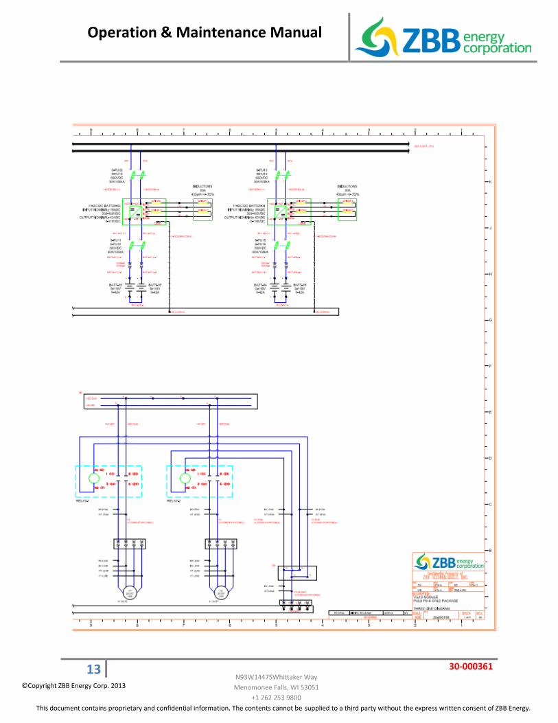
2.2 Electrical Schematic
Refer to the following Drawing # 20-000198 for the Electrical Three Line Diagram for the ZBB EnerStore® 50V3.1(C) Flow Battery Module.

Operation & Maintenance Manual
12 30-000361
N93W14475Whittaker Way Menomonee Falls, WI 53051
+1 262 253 9800 This document contains proprietary and confidential information. The contents cannot be supplied to a third party without the express written consent of ZBB Energy.
©Copyright ZBB Energy Corp. 2013
Operation & Maintenance Manual
13 30-000361
N93W14475Whittaker Way Menomonee Falls, WI 53051
+1 262 253 9800 This document contains proprietary and confidential information. The contents cannot be supplied to a third party without the express written consent of ZBB Energy.
©Copyright ZBB Energy Corp. 2013

Operation & Maintenance Manual
14 30-000361
N93W14475Whittaker Way Menomonee Falls, WI 53051
+1 262 253 9800 This document contains proprietary and confidential information. The contents cannot be supplied to a third party without the express written consent of ZBB Energy.
©Copyright ZBB Energy Corp. 2013

Operation & Maintenance Manual
15 30-000361
N93W14475Whittaker Way Menomonee Falls, WI 53051
+1 262 253 9800 This document contains proprietary and confidential information. The contents cannot be supplied to a third party without the express written consent of ZBB Energy.
©Copyright ZBB Energy Corp. 2013

Operation & Maintenance Manual
16 30-000361
N93W14475Whittaker Way Menomonee Falls, WI 53051
+1 262 253 9800 This document contains proprietary and confidential information. The contents cannot be supplied to a third party without the express written consent of ZBB Energy.
©Copyright ZBB Energy Corp. 2013
3.0 General Safety
3.1 General Safety - Electrical
[WARNING]
Energizing control voltages (24VDC or less) & low voltages (600V or less) shall be conducted in a manner that prevents damage to personnel & equipment.
Table 1- ZBB Battery Stack Electrical Ratings
VDC ADC
120 40
Table 2- ZBB Battery Enclosure Electrical Ratings
VDC ADC
450 800
[CAUTION]
Work shall only be done by qualified personnel only.
If work is involved in connecting additional equipment to existing equipment, ensure that incoming power is disconnected before work is begun. Disconnecting means should be locked out and/or tagged out. Where it is not feasible to de-energize the system (charged battery) the following precautions should be taken:
i. Person(s) working near exposed parts that are or maybe energized should be instructed and should use practices (appropriate apparel, equipment and tools) in accordance to NEC safety codes or governing bodies.
Operation & Maintenance Manual
17 30-000361
N93W14475Whittaker Way Menomonee Falls, WI 53051
+1 262 253 9800 This document contains proprietary and confidential information. The contents cannot be supplied to a third party without the express written consent of ZBB Energy.
©Copyright ZBB Energy Corp. 2013
ii. Person(s) working on exposed parts that are or may be energized should in addition, be qualified personnel who have been trained to work on energized circuits.
Each section will additionally list appropriate steps & safety precautions when energizing or handling energized equipment. Personnel conducting commissioning SHALL READ THROUGH EACH SECTION PRIOR TO PROCEEDING.
All work should be done in accordance with local safety laws and codes.
3.2 General Safety – Chemical
[WARNING]
Electrolyte is caustic and considered a toxic chemical! Wear rubber gloves when working with it. Use baking soda or a baking soda – water solution to neutralize any spills. Isopropanol (isopropyl alcohol) can also be used on minor splashes or spills. Electrolyte left on the skin will burn. Electrolyte left on untreated or unpainted metallic surfaces will accelerate corrosion/rust.
Refer to MSDS for specifics on Electrolyte.
4.0 Setup and Installation Guide Lines
4.1 ZBB EnerStore® 50V3.1(C) Setup Procedure
At time of receipt, the EnerStore 50V3 Flow Battery module should be inspected for any physical damage by the customer. All physical damage shall be recorded and described; and if possible, photographs of the damage should be taken and reported to the party responsible for shipping for further coordination with the transport company. Inspection – A battery system will normally consist of the following major components:
• EnerStore 50V3 Enclosure cabinet • Qty 8 Battery Stacks • Qty 4 DC/DC Converters • Qty 1 Heat Exchanger

Operation & Maintenance Manual
18 30-000361
N93W14475Whittaker Way Menomonee Falls, WI 53051
+1 262 253 9800 This document contains proprietary and confidential information. The contents cannot be supplied to a third party without the express written consent of ZBB Energy.
©Copyright ZBB Energy Corp. 2013
• Qty 2 Pumps for electrolyte • APC control Board • Electrolyte Barrels • Other equipment as ordered per customer request
Examine equipment to ensure all doors open as designed; no electrical component has sustained “breaking force,” or water damage. Where possible, check plumbing fixtures – looking for signs of obvious trauma, abuse and / or damage. Lifting & Handling
• The ZBB EnerStore® 50V3 system cabinet includes the battery module. As shipped, the ZBB EnerStore® 50V3 will weigh approximately 2096 pounds (953 kilograms) with no electrolyte in the module tanks. As designed, the entire cabinet can be lifted with a fork truck having a lift capacity of 5000 pounds (2300 kilograms) or greater.
FIGURE: 01
EnerStore 50V3.1(C) Lifting Pockets
24 VDC PSU
BATTERY
Electrolyte Tank
Electrolyte Pump
APC Control PCB
DC-DC Converter
Heat Exchanger Fan
Heat Exchanger
Electrolyte Pump

Operation & Maintenance Manual
19 30-000361
N93W14475Whittaker Way Menomonee Falls, WI 53051
+1 262 253 9800 This document contains proprietary and confidential information. The contents cannot be supplied to a third party without the express written consent of ZBB Energy.
©Copyright ZBB Energy Corp. 2013
Figure-1 shows the lift points of a 50V3.1(C) cabinet and where the components are physically mounted within the cabinet.
4.2 INSTALLATION
Wire, cable, fiber optic cable, and conduit shall be provided by customer. Bus connections are made using DC BUSBAR interconnect kit provided by ZBB to connect to ZBB EnerSections. Please refer to drawing 20-000063 in Section 2.0 for more details. System schematics, system interconnection wiring and grounding requirements are provided in section 2.0 of O&M Manual.
Chemical Only ZBB technical services personnel are to fill the electrolyte and brominated electrolyte before 1st start up.
400VDC BUSBAR for Interconnection
Stud for Ground Connection

Operation & Maintenance Manual
20 30-000361
N93W14475Whittaker Way Menomonee Falls, WI 53051
+1 262 253 9800 This document contains proprietary and confidential information. The contents cannot be supplied to a third party without the express written consent of ZBB Energy.
©Copyright ZBB Energy Corp. 2013
Use baking soda or a baking soda – water solution to neutralize any spills. Isopropanol (isopropyl alcohol) can also be used on minor splashes or spills. Electrolyte left on the skin will burn. Electrolyte left on untreated or unpainted metallic surfaces will accelerate corrosion/rust.
4.3 ENERSTORE 50V3.1(C) TYPICAL OPERATION
DISCHARGE:
• When the battery is fully discharged, the ANOLYTE and CATHOLYTE tanks should be approximately even
CHARGE • As the battery is charged, the CATHOLYTE should decrease because of the increased
density and viscosity as it charges PARTIALLY CHARGE
• When partially charged, the ANOLYTE should be slightly above the CATHOLYTE level.
ANOLYTE CATHOLYTE 2ND PHASE CATHOLYTE

Operation & Maintenance Manual
21 30-000361
N93W14475Whittaker Way Menomonee Falls, WI 53051
+1 262 253 9800 This document contains proprietary and confidential information. The contents cannot be supplied to a third party without the express written consent of ZBB Energy.
©Copyright ZBB Energy Corp. 2013
4.4 ZBB ENERSTORE® 50V3.1(C) ELECTROLYTE: PROCEDURE FOR FILLING AND REMOVAL
Equipment:
1. Drum pump; [e.g. Standard Pump – SP-PVDF-39 or Sethco P-80; Finish Thompson Model S-1]. The pumps are Kynar tubing and piping. Tube length is 39 inches; motor voltage 120VAC or 240VAC [Figure-1].
2. Sodium Bicarbonate (baking soda) or Sodium Carbonate (soda ash). 3. Cloth rags or heavy duty paper towels. 4. Squirt bottle of Isopropyl alcohol (Isopropanol). 5. Clean water
The following hose and fittings are used to make the necessary connections between the pump and tank fittings.
6. 10 feet of 4879 Viton Chemical hose; 1 inch ID diameter. 7. 1 – Kynar Elbow fittings, 1 inch barb to 1 inch male pipe thread; Ryan Herco Flow
Solutions. 8. 1 - BANJO female coupler –to- female thread (polypropylene), 1.25 inch ID. 9. 1 – BANJO 1.5 inch plug for female coupler (polypropylene); drum pump hose end. 10. 1 – Kynar 1 inch male pipe thread by 1 inch barb hose adapter. 11. 2 – Oetiker 1 inch step-less, stainless steel, spring clamps.
CAUTION: Electrolyte is corrosive; and is an inhalation hazardous. Wear rubber gloves, Respirator and safety glasses when working with it. Refer to MSDS sheet. Electrolyte left on the skin will cause skin irritation. Electrolyte left on untreated or unpainted metallic surfaces will accelerate corrosion/rust. Use dry Sodium Bicarbonate [baking soda] to neutralize fluid spills. Keep a solution of sodium bicarbonate and water handy for general clean-up. Isopropanol (isopropyl alcohol) can be used on minor splashes or spills. Oil dry or similar absorbant material can also be used to assist in fluid clean-ups, after neutralization.

Operation & Maintenance Manual
22 30-000361
N93W14475Whittaker Way Menomonee Falls, WI 53051
+1 262 253 9800 This document contains proprietary and confidential information. The contents cannot be supplied to a third party without the express written consent of ZBB Energy.
©Copyright ZBB Energy Corp. 2013
NOTE: The fittings and hose type currently used are based on their history of reliability and compatibility with the zinc-bromine electrolyte; the fittings called out are specific to the Sethco pump. No fittings are currently used with the Finish Thompson pump because the hose is much more flexible, therefore easier to maneuver into the tanks and drum.
Figure-1 (Sethco drum pump)

Operation & Maintenance Manual
23 30-000361
N93W14475Whittaker Way Menomonee Falls, WI 53051
+1 262 253 9800 This document contains proprietary and confidential information. The contents cannot be supplied to a third party without the express written consent of ZBB Energy.
©Copyright ZBB Energy Corp. 2013
Figure-2 (Finish Thompson drum pump)
Figure-3
Figure-3 (left) shows an example of a drum wrench used to open electrolyte barrels.

Operation & Maintenance Manual
24 30-000361
N93W14475Whittaker Way Menomonee Falls, WI 53051
+1 262 253 9800 This document contains proprietary and confidential information. The contents cannot be supplied to a third party without the express written consent of ZBB Energy.
©Copyright ZBB Energy Corp. 2013
Figure-4
The extender tube shown at the top of the picture is very useful when pumping electrolyte into a barrel. The tube and fittings are optional and not accounted for in the equipment section.

Operation & Maintenance Manual
25 30-000361
N93W14475Whittaker Way Menomonee Falls, WI 53051
+1 262 253 9800 This document contains proprietary and confidential information. The contents cannot be supplied to a third party without the express written consent of ZBB Energy.
©Copyright ZBB Energy Corp. 2013
Figure-5
SAFETY The zinc-bromine electrolyte is corrosive. It will irritate and/or burn bare skin if left untreated. Always wear some type of rubber gloves (e.g. disposable nitrile gloves) when working with electrolyte. Safety glasses are highly recommended as is an apron, smock or coveralls. It is recommended that when working with electrolyte some sort of respirator designed for chemicals should be worn. Electrolyte Filling The V-3 module has a total electrolyte capacity of 130 gallons, distributed across three plastic tanks. From left to right looking at the front of the module: 2nd phase tank, catholyte tank, anolyte tank; Figure-5.
FLUID REMIOVAL / FILL PORT, Anolyte TANK.
FLUID REMOVAL / FILL PORT, 2nd Phase and Catholyte Tanks

Operation & Maintenance Manual
26 30-000361
N93W14475Whittaker Way Menomonee Falls, WI 53051
+1 262 253 9800 This document contains proprietary and confidential information. The contents cannot be supplied to a third party without the express written consent of ZBB Energy.
©Copyright ZBB Energy Corp. 2013
There is no specified order to which the tanks get filled. The anolyte and catholyte tanks hold approximately 50 gallons apiece, the 2nd phase tank 30 gallons. Open a barrel of electrolyte and put the Kynar Tube of the drum pump into the barrel; depending on the model of drum pump used – either the hose end or the plastic tube fits into the quick fill port of the tank. Fill each tank to the point where the vertical face of the tank breaks at a 30 degree angle just below the fill port opening.
Figure-6
NOTE: With tank filling completed ensure the fill port plugs have 8 to 9 wraps ofTeflon tape on the treads. There is no specific torque spec used for tightening the plugs; turn each one in all the way. Replace and tighten the barrel cap. Clean up any spilled electrolyte with a sodium bicarbonate/water solution.
Fill Point

Operation & Maintenance Manual
27 30-000361
N93W14475Whittaker Way Menomonee Falls, WI 53051
+1 262 253 9800 This document contains proprietary and confidential information. The contents cannot be supplied to a third party without the express written consent of ZBB Energy.
©Copyright ZBB Energy Corp. 2013
Electrolyte Emptying Removing electrolyte from the tanks is the reverse of the filling process. The drum pump Kynar tube goes directly into the tank and the Viton hose with fitting(s) goes into the drum. There is one caveat to removing fluid from the electrolyte tank(s): Ensure the fluid in the tank is not higher than the fill port cap!!! As can be expected – if that is the case and the cap is opened there will be a sizable electrolyte spill.
5.0 Operations Instructions Enable/Disable the EnerStore® 50V3.1(C) Flow Battery Module(s) via the ZBB ECM (EnerSystem™ Communications Module). The customer provided communications controller will provide the necessary commands to operate the system based on application specific parameters.
EnerStore 50V3.1(C) operation:
The 50V3.1(C) is Enabled and Disabled locally by the ZBB supplied ECM, and remotely through a ModBus TCP/IP protocol via customer supplied controls. To enable a V3, the DC bus voltage needs to be at 350 VDC or more for the unit to come online. At the ECM, the 50V3.1(C) (V3) is enabled, when the operator selects the V3 they wish to bring online, and presses the “Enable” button on the HMI. When the V3 receives the “Enable” command, the V3 will power up and come online within a variable start time (7secs to 15 min). Start time will depend on what state the V3 module was in before the enable was issued. During the start time, the status of the V3 will show “Wake Up”. Once the enable command is received to a 50V3.1(C) control board (APC), it will perform a hardware check. After the hardware check is completed, the APC will turn on both the Anolyte and Catholyte pumps and start pumping electrolyte throughout the
INVERTER/PV/GEN/ ALTERNATE ENERGY
SOURCE (FOR CHARGING / DISCHARGING)
ENERSTORE 50V3.1(C) CHARGING > 420VDC
DISCHARGING ≤ 410VDC (25KW, 50KWH)
ECM (CONTROL AND COMMUNICATION)

Operation & Maintenance Manual
28 30-000361
N93W14475Whittaker Way Menomonee Falls, WI 53051
+1 262 253 9800 This document contains proprietary and confidential information. The contents cannot be supplied to a third party without the express written consent of ZBB Energy.
©Copyright ZBB Energy Corp. 2013
cell stacks. The 50V3.1(C) controller will initialize all valves to confirm their status and report any faults. Then, the 50V3.1(C) controller sends an enable command to all DC - DC Converters. All DC - DC Converters will initialize a start-up, and come online. Once the V3 completes the initialization process and comes online, the V3 status will change to “Online”, and depending on its State (STRIP, CHARGE/DISCHARGE, TRIP, ALERT) it will react to the DC BUS voltage to CHARGE or DISCHARGE. If the BUS voltage is over 420VDC, it will start to charge. Once all stacks reach 100% SoC (State of Charge), the DC-DC Converters will stop charging the stacks until SoC < 95%. Once the SoC reaches 95%, the DC-DC converters will start charging the stacks until they reach 100% SoC.
The DC voltage level is controlled by ZBB inverter or customer supplied inverters or Generator under license agreement from ZBB Energy. Voltage levels above are factory default settings.
* Between 420 to 430VDC the battery will allow between 0-100% full amperage of charge, respectively
** Between 410 to 390VDC the battery will allow between 0-100% full amperage of discharge, respectively, provided SOC minimum is not reached.
450 VDC
420 VDC
410 VDC
350 VDC
450 VDC
420 VDC
410 VDC
350 VDC
Battery System Trip Possible Equipment Damage
Battery System Charging From ZBB Inverter or
Customer PV Source and/or Customer Generator Source
Battery System NOT Charging or Discharging
Battery System Discharging
430 VDC* 430 VDC*
390 VDC** 390 VDC**
Battery System Trip Possible Equipment Damage

Operation & Maintenance Manual
29 30-000361
N93W14475Whittaker Way Menomonee Falls, WI 53051
+1 262 253 9800 This document contains proprietary and confidential information. The contents cannot be supplied to a third party without the express written consent of ZBB Energy.
©Copyright ZBB Energy Corp. 2013
When the DC BUS is below or equal to 410VDC, the V3 goes into Discharge mode. The discharge kW amount will depend on the level of kW requested from the system, up to a maximum limit of 25KW per V3. The V3 will discharge until the bus voltage can no longer be maintained, or its SoC is at 0%. Should the DC BUS voltage fall below 350VDC, the V3 will not guaranty export of power.
While the V3 is operational, a Disable command, received from the Client by remote or local control, will initiate a shutdown process and report its status as “Shutdown”. The V3, will then disable the DC - DC converters, will cease to import or export power. After a predetermined amount of time, the pumps inside the V3 will also shutdown. Once the shutdown process is complete, the V3 will report its status as “OFFLINE”
After approximately 36 hours of charging and discharging, the V3 module will begin a deep discharge cycle, known as a strip cycle. The V3 will go into a discharge mode, and bring the SoC of its cell stacks to 0%. After the strip process, if the bus voltage is > 350 VDC, the V3 will stay in an idle mode until the bus voltage is raised to 420 VDC. The duration of the Strip cycle varies depending upon; the SoC of the V3 in Strip, the SoC of other V3s if connected, if the system is charging or discharging, and what kW levels the system is charging or discharging. Through local or remote commands, the strip cycle can be expedited by up to 34 hours.
Below is a typical V3’s sequence of Operation.

Operation & Maintenance Manual
30 30-000361
N93W14475Whittaker Way Menomonee Falls, WI 53051
+1 262 253 9800 This document contains proprietary and confidential information. The contents cannot be supplied to a third party without the express written consent of ZBB Energy.
©Copyright ZBB Energy Corp. 2013

Operation & Maintenance Manual
31 30-000361
N93W14475Whittaker Way Menomonee Falls, WI 53051
+1 262 253 9800 This document contains proprietary and confidential information. The contents cannot be supplied to a third party without the express written consent of ZBB Energy.
©Copyright ZBB Energy Corp. 2013
6.0 General Maintenance The ZBB EnerStore® 50V3.1(C) Flow Battery Module should be checked on a regular basis, monthly to twice per year depending upon site conditions. Ensure that there is no debris, no unwanted rodents/insects/etc. nesting inside the unit, and check the air filters on the doors. If the filters on the doors appear to be congested with debris, remove and replace. Contact ZBB if there is a need to purchase more filters.
The electrolyte within the module is reusable between the stack replacements at the set intervals provided it has been operated within its designed specification characteristics.
Maintenance Checklist included in the back of this Manual.
• Automatic – A Pre-programmed equalization cycle will occur approximately every 36 hours during operation to reset the EnerStore® battery stacks. This function can be forced, or intentionally reached, upon the full discharge of the module allowing each stack to reach “0” DCV. Depending on the SoC prior to the discharge, it can take from four to six hours for the full cycle.
• End User – A Monthly visual check should be performed by the End User to ensure that there is no damage or abnormalities.
• ZBB Technician – Monthly Monitoring/Reporting can be performed provided there is customer- established remote internet accessibility. This allows the capability of continuous system recording through analyzed key parameters, updates, and alarm conditions to allow proper operation. **
• ZBB Technician – Standard Annual Inspection of the operating system. Address any items regarding maintenance of the system to assure continued operation. Including System connections, electrical inspections and torque settings will be reviewed under this procedure. (This includes verification of Monthly Maintenance Records, Recording of operation
parameters and measurements, and addressing any identified concerns)** • ZBB Technician – 3-year System Operations Inspection and Performance Evaluation.
Verification of Annual Maintenance records, operation of full range system cycles and performance measurement, energy storage capacity evaluation. **
** These tasks are optional and inclusive to a customer purchased extended warranty and ZBB maintenance program.

Operation & Maintenance Manual
32 30-000361
N93W14475Whittaker Way Menomonee Falls, WI 53051
+1 262 253 9800 This document contains proprietary and confidential information. The contents cannot be supplied to a third party without the express written consent of ZBB Energy.
©Copyright ZBB Energy Corp. 2013
Frequency Description Action By Date Comments
Alternate Days
Perform Cell Equalization Cycle* Occurs automatically every 36 hours Approximately 4 – 12 hours per ZBB
EnerStore® Module depending on module SoC
N/A
Monthly
External Visual Observation for Damage, abnormalities, etc. Inspection/Operations Approximately 1 hour per ZBB EnerStore®
Module
End User
Monthly
Remote Monitoring and Reporting Using Customer Supplied Internet Connection System continuously monitored for
operations, key parameters, analyzed data, and alarm conditions
Approximately 2 -4 hours per ZBB EnerStore® Module
ZBB Tech (Remote)
Annual
System Inspection Inspection of each module and individual
component operations Mechanical connections, torque settings,
standard operations Electrical connections, standard operations Internal module cabinet basic cleaning Verification of monthly maintenance and
records Record operating parameters and internal
measurements Address any noted, or recorded concerns Approximately 1 – 2 days per Module
ZBB Tech (Onsite)

Operation & Maintenance Manual
33 30-000361
N93W14475Whittaker Way Menomonee Falls, WI 53051
+1 262 253 9800 This document contains proprietary and confidential information. The contents cannot be supplied to a third party without the express written consent of ZBB Energy.
©Copyright ZBB Energy Corp. 2013
Frequency Description Action By Date Comments
3-Year
System Inspection and Performance Evaluation Verify annual maintenance and system
operations records Perform full range of system operations
and measure performance factors and standard parameter comparison
Extended Measurements and operations modes to determine state of energy storage capacity of each module
Address any identifiable items or concerns Approximately 1 -2 days per ZBB
EnerStore® Module
*See Description and details in Section 6 of Manual

Operation & Maintenance Manual
34 30-000361
N93W14475Whittaker Way Menomonee Falls, WI 53051
+1 262 253 9800 This document contains proprietary and confidential information. The contents cannot be supplied to a third party without the express written consent of ZBB Energy.
©Copyright ZBB Energy Corp. 2013
7.0 Fault Codes / Tech Support
WARNING! Do not attempt any measurement, parts replacement or other service procedure not described in this manual. Such action will void the warranty, may endanger correct operation and increase downtime and expense.
WARNING! All electrical installation and maintenance work described in this chapter should only be undertaken by qualified service personnel. The safety instructions in section General Safety must be followed.
EnerStore® 50V3.1(C) Fault Code – Lookup Table
The ZBB EnerStore® 50V3.1(C) generates fault code(s) as defined by the Excel spreadsheet 30-000332 – V3 X sw 3 44 APC EVENT Code – Ring Decoder.xlsx . It is possible to get multiple faults depending on the decimal value. For instance, should you get a decimal value of 3, you will have both a temperature ambient over and a temperature anolyte over fault. To use the spreadsheet, enter the hexadecimal number for Fault, Fault 2, Alert, or Alert 2 area from the ECM into the Enter Hex number cell. Below the cell, you will get a decimal value. Place that decimal value either into the EVENT Code 1 Parameter for Alert or Fault code, or into EVENT Code 2 Parameter for Alert 2 or Fault 2 code. The spreadsheet will highlight what faults are associated with the value that is entered.

Operation & Maintenance Manual
35 30-000361
N93W14475Whittaker Way Menomonee Falls, WI 53051
+1 262 253 9800 This document contains proprietary and confidential information. The contents cannot be supplied to a third party without the express written consent of ZBB Energy.
©Copyright ZBB Energy Corp. 2013
Step 1. Enter HEX value into the Highlighted Field, result below (Note: for HMI USE ONLY, If not applicable skip to step 2.)Enter HEX # from 0 to FFFFFFFF >>>
DEC Result >>> 0
Step 2. Enter DEC value from Step 1 or from interface into Event Code 1 or 2 into the Highlighted Field. The appropiate faults will be highlighted dar Enter DEC # from 0 to 2^32 >>>>Enter DEC # from 0 to 2^32 >>>>
Flag BIT #Temperature Ambient Over 0 0 0 0 0Temperature Anolyte out Over 0 0 0 0 1Bus Under Voltage 0 0 0 0 2Batt Over Current 0 0 0 0 3
0 0 0 0 4Batt 1 Over Voltage Failure 0 0 0 0 5Batt 2 Over Voltage Failure 0 0 0 0 6Batt 3 Over Voltage Failure 0 0 0 0 7Batt 4 Over Voltage Failure 0 0 0 0 8Converter 1 No Comm 0 0 0 0 9Converter 2 No Comm 0 0 0 0 10Converter 3 No Comm 0 0 0 0 11Converter 4 No Comm 0 0 0 0 12Batt 1 Under Voltage Failure 0 0 0 0 135 or more of 8 total converters faulted or no comm OR3 or more of 4 total converters faulted or no comm
0 0 0 0 14
Valve 2W Over Current 0 0 0 0 15Valve 2W Time Out 0 0 0 0 16Valve 2W Under Current 0 0 0 0 17Valve 4W Over Current 0 0 0 0 18Valve 4W Time Out 0 0 0 0 19Valve 4W Under Current 0 0 0 0 20Leak Low 0 0 0 0 21Leak High Failure 0 0 0 0 22Batt 2 Under Voltage Failure 0 0 0 0 23Batt 3 Under Voltage Failure 0 0 0 0 24Converter 1 Faulted 0 0 0 0 25Converter 2 Faulted 0 0 0 0 26Converter 3 Faulted 0 0 0 0 27Converter 4 Faulted 0 0 0 0 28Temperature Ambient Under 0 0 0 0 29Temperature Anolyte Under 0 0 0 0 30Batt 4 Under Voltage Failure 0 0 0 0 31
Flag BIT #Converter 5 No Comm 0 0 0 0 0Converter 6 No Comm 0 0 0 0 1Converter 7 No Comm 0 0 0 0 2Converter 8 No Comm 0 0 0 0 3Converter 5 Faulted 0 0 0 0 4Converter 6 Faulted 0 0 0 0 5Converter 7 Faulted 0 0 0 0 6Converter 8 Faulted 0 0 0 0 7Batt 5 Over Voltage Failure 0 0 0 0 8Batt 6 Over Voltage Failure 0 0 0 0 9Batt 7 Over Voltage Failure 0 0 0 0 10Batt 8 Over Voltage Failure 0 0 0 0 11Pump Anolyte Over RPM 0 0 0 0 12Pump Anolyte Under RPM 0 0 0 0 13Pump Anolyte Over Current 0 0 0 0 14Pump Anolyte Under Current 0 0 0 0 15Pump Catholyte Over RPM 0 0 0 0 16Pump Catholyte Under RPM 0 0 0 0 17Pump Catholyte Over Current 0 0 0 0 18Pump Catholyte Under Current 0 0 0 0 19Batt 5 Under Voltage Failure 0 0 0 0 20Batt 6 Under Voltage Failure 0 0 0 0 21Batt 7 Under Voltage Failure 0 0 0 0 22Batt 8 Under Voltage Failure 0 0 0 0 23
0 0 0 0 24
< Enter EVENT Code 1 Parameter 9000, 9001< Enter EVENT Code 2 Parameter 9002, 9003
REV0.0
1.0 HCB ADDED BATT UNDERVOLTAGE & PUMP FAULTS PER EC-0344.
HISTORY:DESCRIPTION
INITIAL RELEASE
DATE:
09/05/13
ISSUER
HCB
10/17/13

Operation & Maintenance Manual
36 30-000361
N93W14475Whittaker Way Menomonee Falls, WI 53051
+1 262 253 9800 This document contains proprietary and confidential information. The contents cannot be supplied to a third party without the express written consent of ZBB Energy.
©Copyright ZBB Energy Corp. 2013
Table 1 Alarm or Fault
Fault Code (Bit) Name Cause What to do
1 (0)
Temperature Ambient Over
Temperature inside V3.1 is too high
Check ambient temperature inside enclosure by heat exchanger Open doors to allow additional cooling Restart unit once temperature gets below 50 degrees C Contact ZBB should fault continue
2 (1)
Temperature Anolyte Over
Anolyte temperature is too high
Stop charging / discharging
Keep unit enabled to allow pumps to run
Put unit into strip by adjusting strip cycle counter Contact ZBB should fault continue
4 (2)
Bus Under Voltage
Main DC bus is less than 325 VDC
Verify ZBB EnerSection is enabled If V3.1 is connected to other sources, verify the DC bus is above 325 VDC. Contact ZBB should fault continue
8 (3)
Battery Over Current
Controller instability
Check DC Load Wiring, cycle power Contact ZBB
32 (5)
Battery 1 Over Voltage Failure
Cell stack voltage is over 240 VDC (V3.1), 120 VDC (V3)
Put unit into strip cycle by adjusting strip cycle counter Contact ZBB should fault continue
64 (6)
Battery 2 Over Voltage Failure
Cell stack voltage is over 240 VDC (V3.1), 120 VDC (V3)
Put unit into strip cycle by adjusting strip cycle counter Contact ZBB should fault continue
128 (7)
Battery 3 Over Voltage Failure
Cell stack voltage is over 240 VDC (V3.1), 120 VDC (V3)
Put unit into strip cycle by adjusting strip cycle counter Contact ZBB should fault continue
256 (8)
Battery 4 Over Voltage Failure
Cell stack voltage is over 240 VDC (V3.1), 120 VDC (V3)
Put unit into strip cycle by adjusting strip cycle counter Contact ZBB should fault continue

Operation & Maintenance Manual
37 30-000361
N93W14475Whittaker Way Menomonee Falls, WI 53051
+1 262 253 9800 This document contains proprietary and confidential information. The contents cannot be supplied to a third party without the express written consent of ZBB Energy.
©Copyright ZBB Energy Corp. 2013
Fault Code
Name Cause What to do
512 (9)
Converter 1 No Comm
DC-DC Converter has stopped communicating to the V3.1 controller
Verify lights are on DC-DC converter red/green LEDs Verify fuses are not blown to DC-DC converter FU01, FU02 Contact ZBB
1024 (10)
Converter 2 No Comm
DC-DC Converter has stopped communicating to the V3.1 controller
Verify lights are on DC-DC converter red/green LEDs Verify fuses are not blown to DC-DC converter FU05, FU06 (V3.1), FU03, FU04 (V3) Contact ZBB
2048 (11)
Converter 3 No Comm
DC-DC Converter has stopped communicating to the V3.1 controller
Verify lights are on DC-DC converter red/green LEDs Verify fuses are not blown to DC-DC converter FU09, FU10 (V3.1), FU05, FU06 (V3) Contact ZBB
4096 (12)
Converter 4 No Comm
DC-DC Converter has stopped communicating to the V3.1 controller
Verify lights are on DC-DC converter red/green LEDs Verify fuses are not blown to DC-DC converter FU13, FU14 (V3.1), FU07, FU08 (V3) Contact ZBB
8192 (13)
Battery 1 Under Voltage Failure
Cell stack has not reached a minimum voltage while charging
Verify fuses are not blown to Cell Stacks FU03, FU04 Put unit into strip cycle by adjusting strip cycle counter Contact ZBB
16384 (14)
5 or more of 8 total converters
faulted or no comm OR
3 or more of 4 total converters
faulted or no comm
DC-DC Converter has stopped communicating to the V3.1 controller or it has faulted
Verify lights are on DC-DC converter red/green LEDs Verify fuses are not blown to DC-DC converter Contact ZBB
32768 (15)
Valve 2W Over Current
Valve is drawing more current than rated, possibly caused by the valve binding in the piping
Disable and enable V3.1 to clear fault Contact ZBB should fault continue
65536 (16)
Valve 2W Time Out
Valve has not opened or closed within the allotted time
Disable and enable V3.1 to clear fault Contact ZBB should fault continue

Operation & Maintenance Manual
38 30-000361
N93W14475Whittaker Way Menomonee Falls, WI 53051
+1 262 253 9800 This document contains proprietary and confidential information. The contents cannot be supplied to a third party without the express written consent of ZBB Energy.
©Copyright ZBB Energy Corp. 2013
Fault Code
Name Cause What to do
131072 (17)
Valve 2W Under Current
Valve is drawing less current than rated, possibly caused by actuator decoupling from valve
Disable and enable V3.1 to clear fault Contact ZBB should fault continue
262144 (18)
Valve 4W Over Current
Valve is drawing more current than rated, possibly caused by the valve binding in the piping
Disable and enable V3.1 to clear fault Contact ZBB should fault continue
524288 (19)
Valve 4W Time Out
Valve has not opened or closed within the allotted time
Disable and enable V3.1 to clear fault Contact ZBB should fault continue
1048576 (20)
Valve 4W Under Current
Valve is drawing less current than rated, possibly caused by actuator decoupling from valve
Disable and enable V3.1 to clear fault Contact ZBB should fault continue
2097152 (21)
Leak Low Fluid has reached the low level sensor in the containment area
Check the V3.1 for leaks Check wiring and contacts of leak sensor LS-2 Contact ZBB
4194304 (22)
Leak High Failure Fluid has reached the high level sensor in the containment area
Check the V3.1 for leaks Check wiring and contacts of leak sensor LS-1 Contact ZBB
8388608 (23)
Battery 2 Under Voltage Failure
Cell stack has not reached a minimum voltage while charging
Verify fuses are not blown to Cell Stacks FU03, FU04 Put unit into strip cycle by adjusting strip cycle counter Contact ZBB
16777216 (24)
Battery 3 Under Voltage Failure
Cell stack has not reached a minimum voltage while charging
Verify fuses are not blown to Cell Stacks FU03, FU04 Put unit into strip cycle by adjusting strip cycle counter Contact ZBB

Operation & Maintenance Manual
39 30-000361
N93W14475Whittaker Way Menomonee Falls, WI 53051
+1 262 253 9800 This document contains proprietary and confidential information. The contents cannot be supplied to a third party without the express written consent of ZBB Energy.
©Copyright ZBB Energy Corp. 2013
Fault Code
Name Cause What to do
33554432 (25)
Converter 1 Faulted DC-DC Converter has faulted
Verify lights are on DC-DC converter red/green LEDs Verify fuses are not blown to DC-DC converter Contact ZBB
67108864 (26)
Converter 2 Faulted DC-DC Converter has faulted
Verify lights are on DC-DC converter red/green LEDs Verify fuses are not blown to DC-DC converter Contact ZBB
134217728 (27)
Converter 3 Faulted DC-DC Converter has faulted
Verify lights are on DC-DC converter red/green LEDs Verify fuses are not blown to DC-DC converter Contact ZBB
268435456 (28)
Converter 4 Faulted DC-DC Converter has faulted
Verify lights are on DC-DC converter red/green LEDs Verify fuses are not blown to DC-DC converter Contact ZBB
536870912 (29)
Temperature Ambient Under
Temperature is not above V3.1 Minimum Operating Point
Verify temperature where the V3.1 is located Increase temperature in area where V3.1 is located Contact ZBB should temperature be above minimum operating point
1073741824 (30)
Temperature Anolyte Under
Electrolyte temperature is not above V3.1 Minimum Operating Point
Verify temperature where the V3.1 is located Increase temperature in area where V3.1 is located For V3.1C, verify heat blanket is operating Contact ZBB should temperature be above minimum operating point
2147483648 (31)
Battery 4 Under Voltage Failure
Cell stack has not reached a minimum voltage while charging
Verify fuses are not blown to Cell Stacks FU03, FU04 Put unit into strip cycle by adjusting strip cycle counter Contact ZBB
Table 2 Alarm 1 or Fault 1
Fault Code Name Cause What to do

Operation & Maintenance Manual
40 30-000361
N93W14475Whittaker Way Menomonee Falls, WI 53051
+1 262 253 9800 This document contains proprietary and confidential information. The contents cannot be supplied to a third party without the express written consent of ZBB Energy.
©Copyright ZBB Energy Corp. 2013
Fault Code Name Cause What to do
1 (0)
Converter 5 No Comm
DC-DC Converter has stopped communicating to the V3 controller
Verify lights are on DC-DC converter red/green LEDs Verify fuses are not blown to DC-DC converter FU09, FU10 Contact ZBB
2 (1)
Converter 6 No Comm
DC-DC Converter has stopped communicating to the V3 controller
Verify lights are on DC-DC converter red/green LEDs Verify fuses are not blown to DC-DC converter FU11, FU12 Contact ZBB
4 (2)
Converter 7 No Comm
DC-DC Converter has stopped communicating to the V3 controller
Verify lights are on DC-DC converter red/green LEDs Verify fuses are not blown to DC-DC converter FU13, FU14 Contact ZBB
8 (3)
Converter 8 No Comm
DC-DC Converter has stopped communicating to the V3 controller
Verify lights are on DC-DC converter red/green LEDs Verify fuses are not blown to DC-DC converter FU15, FU16 Contact ZBB
16 (4)
Converter 5 Faulted DC-DC Converter has faulted
Verify lights are on DC-DC converter red/green LEDs Verify fuses are not blown to DC-DC converter Contact ZBB
32 (5)
Converter 6 Faulted DC-DC Converter has faulted
Verify lights are on DC-DC converter red/green LEDs Verify fuses are not blown to DC-DC converter Contact ZBB
64 (6)
Converter 7 Faulted DC-DC Converter has faulted
Verify lights are on DC-DC converter red/green LEDs Verify fuses are not blown to DC-DC converter Contact ZBB
128 (7)
Converter 8 Faulted DC-DC Converter has faulted
Verify lights are on DC-DC converter red/green LEDs Verify fuses are not blown to DC-DC converter Contact ZBB
Operation & Maintenance Manual
41 30-000361
N93W14475Whittaker Way Menomonee Falls, WI 53051
+1 262 253 9800 This document contains proprietary and confidential information. The contents cannot be supplied to a third party without the express written consent of ZBB Energy.
©Copyright ZBB Energy Corp. 2013
Fault Code Name Cause What to do
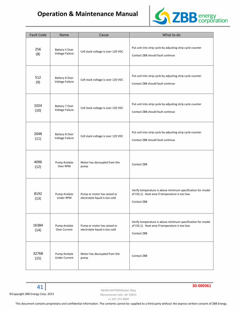
256 (8)
Battery 5 Over Voltage Failure Cell stack voltage is over 120 VDC
Put unit into strip cycle by adjusting strip cycle counter Contact ZBB should fault continue
512 (9)
Battery 6 Over Voltage Failure Cell stack voltage is over 120 VDC
Put unit into strip cycle by adjusting strip cycle counter Contact ZBB should fault continue
1024 (10)
Battery 7 Over Voltage Failure Cell stack voltage is over 120 VDC
Put unit into strip cycle by adjusting strip cycle counter Contact ZBB should fault continue
2048 (11)
Battery 8 Over Voltage Failure Cell stack voltage is over 120 VDC
Put unit into strip cycle by adjusting strip cycle counter Contact ZBB should fault continue
4096 (12)
Pump Anolyte Over RPM
Motor has decoupled from the pump
Contact ZBB
8192 (13)
Pump Anolyte Under RPM
Pump or motor has seized or electrolyte liquid is too cold
Verify temperature is above minimum specification for model of V3(.1). Heat area if temperature is too low. Contact ZBB
16384 (14)
Pump Anolyte Over Current
Pump or motor has seized or electrolyte liquid is too cold
Verify temperature is above minimum specification for model of V3(.1). Heat area if temperature is too low. Contact ZBB
32768 (15)
Pump Anolyte Under Current
Motor has decoupled from the pump
Contact ZBB

Operation & Maintenance Manual
42 30-000361
N93W14475Whittaker Way Menomonee Falls, WI 53051
+1 262 253 9800 This document contains proprietary and confidential information. The contents cannot be supplied to a third party without the express written consent of ZBB Energy.
©Copyright ZBB Energy Corp. 2013
Fault Code Name Cause What to do
65536 (16)
Pump Catholyte Over RPM
Motor has decoupled from the pump
Contact ZBB
131072 (17)
Pump Catholyte Under RPM
Pump or motor has seized or electrolyte liquid is too cold
Verify temperature is above minimum specification for model of V3(.1). Heat area if temperature is too low. Contact ZBB
262144 (18)
Pump Catholyte Over Current
Pump or motor has seized or electrolyte liquid is too cold
Verify temperature is above minimum specification for model of V3(.1). Heat area if temperature is too low. Contact ZBB
524288 (19)
Pump Catholyte Under Current
Motor has decoupled from the pump
Contact ZBB
1048576 (20)
Battery 5 Under Voltage Failure
Cell stack has not reached a minimum voltage while charging
Put unit into strip cycle by adjusting strip cycle counter Contact ZBB
2097152 (21)
Battery 6 Under Voltage Failure
Cell stack has not reached a minimum voltage while charging
Put unit into strip cycle by adjusting strip cycle counter Contact ZBB
4194304 (22)
Battery 7 Under Voltage Failure
Cell stack has not reached a minimum voltage while charging
Put unit into strip cycle by adjusting strip cycle counter Contact ZBB
8388608 (23)
Battery 8 Under Voltage Failure
Cell stack has not reached a minimum voltage while charging
Put unit into strip cycle by adjusting strip cycle counter Contact ZBB

Operation & Maintenance Manual
43 30-000361
N93W14475Whittaker Way Menomonee Falls, WI 53051
+1 262 253 9800 This document contains proprietary and confidential information. The contents cannot be supplied to a third party without the express written consent of ZBB Energy.
©Copyright ZBB Energy Corp. 2013
ZBB SERVICE NUMBERS
SERVICE & TECHNICAL SUPPORT
Address: ZBB Energy Corporation N93 W14475 Whittaker Way Menomonee Falls, Wisconsin 53051 Business hours: United States Central Time Zone – 0700 to 1700 Telephone: 1-262-253-9800 ext 135
Emergency Mobile/Cell Number: + 1 262 442 1216

Operation & Maintenance Manual
30-000361
N93W14475Whittaker Way Menomonee Falls, WI 53051
+1 262 253 9800 ©ZBB Energy Corporation 2013
8.0 Recommended Spare Parts
ZBB Energy Corporation 50V3.1C Recommended Spare PartsEnerStore™ 50V3.1C Module/s Project Total:
Item Description ZBB Part Number Quantity per Module
Recommended No. of Spares
Valve, Ball 32mm, Soc.,Pump shut-off, 2nd Phase discharge 110041 3 1
Actuator, 24 VDC, 90 degree rotation PLUS 2104750 24VDC 120325 2 1
Valve, 4 way, V3.1 610029 1 1
Heat Exchanger 610008 1 1
Pump, DB6H Anolyte 24VDC,250W, 3.63" Impeller 110175 1 1
Pump, DB6H Catholyte 24VDC,250W, 3.63" Impeller 110176 1 1
Sensor,spill,liquid level,24v 120148 2 2
Heat Pad, 66.5 x 22", 1.25 Watts per/in.,1800 Wats@ 600VDC 120356 1 1
Fan, 404 mm, 48 VDC, 1600 CFM 130123 1 1
Fan, 48V DC, 4A 414W, CFM 130441 2 1
V3 Stack (Complete and Tested) 308001 8 2
DC/DC Converter 327346 4 1
Power Supply, In: DC250-500V, Out: DC 24-48V; 20A, PULS 120855 3 1
Auxiliary Power & Control -APC 620005 1 1
Contactor #EV200HAANA 120120 3 1
Fuse, 10A, fast acting, 600VAC/VDC 100kAIR 120872 2 2
Fuse, 15A Fast Acting, 600V, 100kAIR, Midget 120856 4 2
Fuse, 30A Fast Acting, 600V, 100kAIR, Midget 120857 8 4
Fuse, 60A Fast Acting, 600VAC, 200kAIR/300VDC 100kAIR 120858 8 4
Thermosnap, NC, open on rise 15C, QD Terminal 120789 1 1
Thermosnap, NC, open on rise 60C, QD Terminal 120790 1 1
Thermosnap, NC, open on rise 65C, QD Terminal 120788 1 1
Thermosnap, NC, open on rise 80C, QD Terminal 120787 2 1
Thermosnap , OC NC, Temp Range 120381 1 1
Thermocouple, Omega, Self-Adhesive, K-type 120526 2 1
Fan, Axial, 11.8cfm, 24vdc, 5000rpm,-20-70C 130154 1 1
PCB, RJ-45 to Fiber Optic, Interface w/Sync 327307 1 1
EnerStore™ Special Tools
Drum pump/fittings kit (fill and empty) 314701 0 1
Peristaltic Pump 155000 0 1
Operation & Maintenance Manual
45 30-000361
N93W14475Whittaker Way Menomonee Falls, WI 53051
+1 262 253 9800 This document contains proprietary and confidential information. The contents cannot be supplied to a third party without the express written consent of ZBB Energy.
©Copyright ZBB Energy Corp. 2013
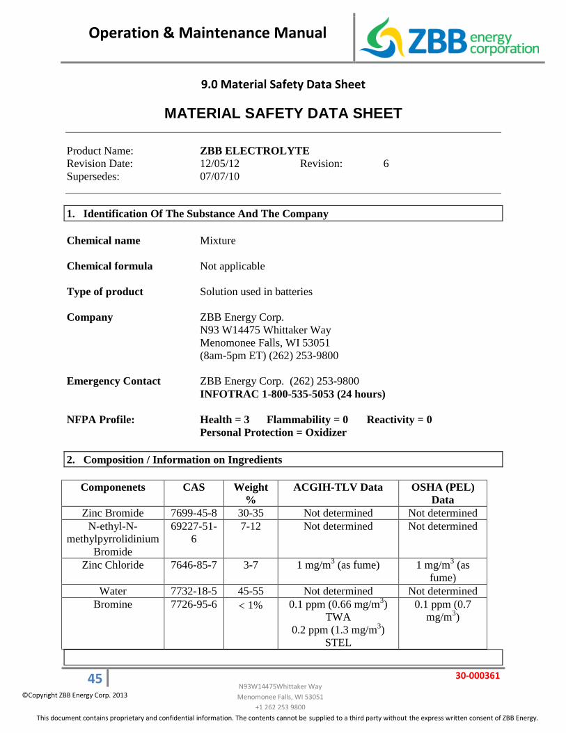
9.0 Material Safety Data Sheet
MATERIAL SAFETY DATA SHEET
Product Name: ZBB ELECTROLYTE Revision Date: 12/05/12 Revision: 6 Supersedes: 07/07/10
1. Identification Of The Substance And The Company Chemical name Mixture Chemical formula Not applicable Type of product Solution used in batteries Company ZBB Energy Corp. N93 W14475 Whittaker Way Menomonee Falls, WI 53051 (8am-5pm ET) (262) 253-9800 Emergency Contact ZBB Energy Corp. (262) 253-9800 INFOTRAC 1-800-535-5053 (24 hours) NFPA Profile: Health = 3 Flammability = 0 Reactivity = 0 Personal Protection = Oxidizer 2. Composition / Information on Ingredients
Componenets CAS Weight %
ACGIH-TLV Data OSHA (PEL) Data
Zinc Bromide 7699-45-8 30-35 Not determined Not determined N-ethyl-N-
methylpyrrolidinium Bromide
69227-51-6
7-12 Not determined Not determined
Zinc Chloride 7646-85-7 3-7 1 mg/m3 (as fume) 1 mg/m3 (as fume)
Water 7732-18-5 45-55 Not determined Not determined Bromine 7726-95-6 < 1% 0.1 ppm (0.66 mg/m3)
TWA 0.2 ppm (1.3 mg/m3)
STEL
0.1 ppm (0.7 mg/m3)

Operation & Maintenance Manual
46 30-000361
N93W14475Whittaker Way Menomonee Falls, WI 53051
+1 262 253 9800 This document contains proprietary and confidential information. The contents cannot be supplied to a third party without the express written consent of ZBB Energy.
©Copyright ZBB Energy Corp. 2013
3. Hazards Identification / Health Information Emergency overview Corrosive to eyes, skin and mucous membranes. May cause skin
sensitization. Bromine vapors are highly irritating and painful to the respiratory tract.
Eye Contact May cause eye irritation. Skin Contact May cause dermatitis. Inhalation May cause irritation to the respiratory tract. Ingestion May cause severe burns to the mucous membranes of the mouth,
esophagus, and stomach, abdominal pain, nausea and vomiting. May cause falling asleep, muscular incoordination and respiratory depression.
4. First Aid Procedures Eye Contact Holding the eyelids apart, flush eyes promptly with copious
flowing water for at least 20 minutes. Get medical attention immediately.
Skin Contact Remove contaminated clothing. Wash skin thoroughly with mild
soap and plenty of water for 15 minutes. Wash clothes before re-use. Get medical attention immediately.
Inhalation In case of inhalation, remove person to fresh air. Keep him quiet
and warm. Apply artificial respiration if necessary and get medical attention immediately.
Swallowing If swallowed, wash mouth thoroughly with plenty of water and
give water or milk to drink. Get medical attention immediately. ************************************************* Note: Never give an unconscious person anything to drink. ************************************************* Notes to physician: Corrosive In case of ingestion DO NOT induce vomiting No specific antidote. Treat symptomatically and supportively.

Operation & Maintenance Manual
47 30-000361
N93W14475Whittaker Way Menomonee Falls, WI 53051
+1 262 253 9800 This document contains proprietary and confidential information. The contents cannot be supplied to a third party without the express written consent of ZBB Energy.
©Copyright ZBB Energy Corp. 2013
5. Fire and explosion hazards Flash point None Auto-ignition Temperature Not applicable Flammable limits in air Not flammable Extinguishing media Material is not combustible. Use extinguishing media appropriate
to surrounding fire conditions. Fire fighting procedures Stay upwind. Avoid any bodily contact. Wear self-contained
breathing apparatus in a positive pressure mode and appropriate protective clothing. Use water from side and from safe distance to keep fire exposed containers cool.
Unusual fire & explosion hazards
When heated to decomposition, may release poisonous and corrosive fumes of hydrobromic acid (HBr) and Bromine (Br2). Although not combustible itself, the fuming liquid will react with combustible materials and may cause them to ignite. Hydrogen, many organic compounds and some metals will burn in a bromine atmosphere.
6. Accidental Release Measures Personal precautions Evacuate area. Full protective clothing, including self-contained breathing
apparatus or power air purifying respirator, must be used. Methods for cleaning up Neutralize, then absorb on sand or vermiculite and place in closed
container for disposal. Ventilate area and wash spill site after material pickup is complete. Avoid access to streams, lakes or ponds.
The following neutralizing agents for bromine are listed in order of neutralizing efficiency:
1. 10-50% potassium carbonate solution 2. 10-30% sodium carbonate solution 3. 5-10% sodium bicarbonate solution 4. Sodium thiosulfate solution (prepared by dissolving 4 kg of
technical grade sodium thiosulfate in 9 liters of water and adding 100 gr of soda ash). Please note that there is a high heat of reaction released in this procedure.
5. 5% magnesium hydroxide slurry (very slow neutralizing action).
6. 5% slaked lime 7. 5% sodium hydroxide solution

Operation & Maintenance Manual
48 30-000361
N93W14475Whittaker Way Menomonee Falls, WI 53051
+1 262 253 9800 This document contains proprietary and confidential information. The contents cannot be supplied to a third party without the express written consent of ZBB Energy.
©Copyright ZBB Energy Corp. 2013
7. Handling and Storage Handling Avoid breathing vapors and any other bodily contact. Keep
containers tightly closed. Storage Store in a dry, well-ventilated area away from incompatible
materials (see “materials to avoid”). 8. Exposure control / personal protection PEL/TWA (OSHA Permissible Exposure Limit/Time Weighted
Average): For Bromine: 0.1 ppm, Not established for other components. TLV/TWA (ACGIH Threshold Limit Value/Time Weighted
Average): For Bromine: 0.1 ppm, Not established for other components.
Ventilation requirements Provide adequate ventilation. Use local exhaust as necessary, especially under misting
conditions. Personal protective equipment: - Respiratory protection Respirator with cartridge providing protection against bromine (up
to 5 ppm) or self-contained breathing apparatus (above 5 ppm). For short term exposure to low concentrations, an approved combination acid gas-organic vapor gas mask is suitable.
The wearer should be warned to get out of the area at the first sign of bromine gas odor coming through the mask.
NIOSH recommendation for respirator selection includes any chemical cartridge respirator with a full face piece and cartridge.
- Hand protection Neoprene or rubber gloves, (tucked under sleeves. - Eye protection Chemical safety goggles or face shield with safety glasses. - Skin and body protection Protective impervious clothing, hard hat and neoprene or rubber
boots. Hygiene measures Avoid bodily contact. Safety shower and eye bath should be provided. Do not eat, drink
or smoke until after-work showering and changing clothes.

Operation & Maintenance Manual
49 30-000361
N93W14475Whittaker Way Menomonee Falls, WI 53051
+1 262 253 9800 This document contains proprietary and confidential information. The contents cannot be supplied to a third party without the express written consent of ZBB Energy.
©Copyright ZBB Energy Corp. 2013
9. Physical And Chemical Properties Appearance and Odor: Yellow to slightly orange liquid with a slightly irritating odor. Boiling Point/Range: 136oC Melting Point/Range: ca. -8oC Vapor Pressure: 5.2 mm Hg at 25oC Specific Gravity: 1.4 - 1.6 Vapor Density (Air = 1) Not available Evaporation (ether = 1) Of water Solubility in Water: Soluble Thermal Decomposition Not available 10. Stability and Reactivity Stability Stable under normal conditions Materials to avoid Strong oxidants Conditions to avoid Not available Hazardous decomposition products Hydrogen bromide and bromine Hazardous polymerization Will not occur 11. Toxicological Information Toxicity: - Rat oral LD50 For zinc bromide 100% (1047 mg/kg) - Rat inhalation LC50 For bromine 2700 mg/m3 - Mouse inhalation LC50 for bromine 750 ppm/9 min. Effects of overexposure - Ocular Corrosive Symptoms include redness, pain and blurred vision. Lachrimation occurs at less than 1 ppm. - Dermal Corrosive. Mild irritant to intact skin - Inhalation Corrosive to mucous membranes and upper respiratory tract.
Symptoms include sore throat, dizziness, headache, nosebleed, coughing, abdominal pain, and sometimes rash. Concentrated bromine vapors may cause severe burns that ulcerate and are slow to heal.
- Ingestion Corrosive by ingestion. Symptoms of inhalation.

Operation & Maintenance Manual
50 30-000361
N93W14475Whittaker Way Menomonee Falls, WI 53051
+1 262 253 9800 This document contains proprietary and confidential information. The contents cannot be supplied to a third party without the express written consent of ZBB Energy.
©Copyright ZBB Energy Corp. 2013
-Chronic toxicity Prolonged exposure may cause chronic bronchitis, contact and allergic dermatitis.
Repeated oral intake of bromides (.9 mg/kg of body weight/day) may affect the central nervous system. Warning symptoms include mental dullness, slurred speech, weakened memory, apathy, anorexia, constipation, drowsiness and loss of sensitivity to touch and pain.
Mutagenicity Not mutagenic by the Ames Test. MEP is positive in in vivo somatic cell mutagenicity assay, the
bone marrow micronucleous test. Carcinogenicity Not known to be a carcinogen. Not classified by IARC. Not included in NPT 10th Annual Report on carcinogens. 12. Ecological Information Ecological Effects Zinc bromide is classified by IMO as a marine pollutant. Bromine is not biodegradable. Because of its high vapor density, bromine id not transferred to the
high atmospheric levels. Note: The following data refer to zinc bromide (ZnBr2) Aquatic toxicity: - 96 Hour-LC50, Fish 115.9 mg/l (Juvenile turbot) - 72 Hour-EC50, Marine alga 6.6 mg/l (Skeletenoma costatum) - 48 Hour-EC50, Marine invertebrate 2.4 mg/l (Acatia tonsa) - 48 Hour-EC50, Daphnia magna 8.8 mg/l 13. Disposal Considerations Waste disposal May be disposed of by absorption on vermiculite or other
equivalent absorbent. Dispose of waste in suitable containers covered with sodium carbonate or bicarbonate. Remove to approved incinerator or landfill. Observe all federal, state and local environmental regulations when disposing of this material.

Operation & Maintenance Manual
51 30-000361
N93W14475Whittaker Way Menomonee Falls, WI 53051
+1 262 253 9800 This document contains proprietary and confidential information. The contents cannot be supplied to a third party without the express written consent of ZBB Energy.
©Copyright ZBB Energy Corp. 2013
14. Transportation Information UN No. 1760 DOT Proper shipping name: Corrosive Liquid, n.o.s. (contains zinc
bromide and bromine) Class: 8 – Corrosives Label: CORROSIVE (8) Marking: MARINE POLLUTANT Packing Group: II IMO Proper shipping name: Corrosive Liquid, n.o.s. (contains zinc
bromide and bromine) Class: 8 – Corrosives Label: CORROSIVE (8) Marking: MARINE POLLUTANT Packing Group: II ICAO / IATA Class: 8 Hazard Label (s): Corrosive Packing Group: II 15. Regulatory Information USA Reported in the EPA TSCA Inventory EPCRA (SARA title III) Zinc compounds and Bromine (CAS #7726-95-6) are subject to
the reporting requirements of section 313 of the Emergency Planning and Community Right-to-Know Act of 1986 and of 40CFR 372.
Section 311/312 Categorization (40CFR 370): Zinc bromide & zinc chloride are categorized as an immediate and delayed health hazard.
Under the provisions of Section 311 of the Clean Water Act, zinc compounds are designated a hazardous substance if discharged in navigable waters. The Reportable Quantity (RQ) for notification is 1,000 lb/454 kg.
EEC Not all ingredients in the preparation are reported in EINECS Japan Listed in MITI Australia Listed in AICS

Operation & Maintenance Manual
52 30-000361
N93W14475Whittaker Way Menomonee Falls, WI 53051
+1 262 253 9800 This document contains proprietary and confidential information. The contents cannot be supplied to a third party without the express written consent of ZBB Energy.
©Copyright ZBB Energy Corp. 2013
16. Other information The information presented herein is believed to be factual as it has
been derived from the works and opinions of persons believed to be qualified experts; however, nothing contained in this information is to be taken as a warranty or representation for which ZBB Technologies, Inc., bears legal responsibility. The user should review any recommendations in the specific context of the intended use to determine whether they are appropriate.
PREPARED BY: ZBB Energy Corp. N93 W14475 Whittaker Way Menomonee Falls, WI 53051 Ph: (262) 253-9800 www.zbbenergy.com ISSUE DATE: December 5, 2012 SUPERSEDES: (April 2, 2008)