working with combinational logic - university of washington · autumn 2006 cse370 - iii - working...
TRANSCRIPT

Autumn 2006 CSE370 - III - Working with Combinational Logic 1
Working with combinational logic
Simplificationtwo-level simplificationexploiting don’t caresalgorithm for simplification
Logic realizationtwo-level logic and canonical forms realized with NANDs and NORsmulti-level logic, converting between ANDs and ORs
Time behaviorHardware description languages
Autumn 2006 CSE370 - III - Working with Combinational Logic 2
block diagramand
truth table
4-variable K-mapfor each of the 4output functions
A2 A1 B2 B1 P8 P4 P2 P10 0 0 0 0 0 0 0
0 1 0 0 0 01 0 0 0 0 01 1 0 0 0 0
0 1 0 0 0 0 0 00 1 0 0 0 11 0 0 0 1 01 1 0 0 1 1
1 0 0 0 0 0 0 00 1 0 0 1 01 0 0 1 0 01 1 0 1 1 0
1 1 0 0 0 0 0 00 1 0 0 1 11 0 0 1 1 01 1 1 0 0 1
Design example: 2x2-bit multiplier
P1P2P4P8
A1A2B1B2

Autumn 2006 CSE370 - III - Working with Combinational Logic 3
K-map for P8 K-map for P4
K-map for P2 K-map for P1
Design example: 2x2-bit multiplier (activity)
0 0
0 0
0 0
0 0B1
A2
0 0
0 0
0 1
1 1
A1
B2
0 0
0 1
0 0
1 0B1
A2
0 1
0 0
1 0
0 0
A1
B2
0 0
0 0
0 0
1 1B1
A2
0 1
0 1
0 1
1 0
A1
B2
0 0
0 0
0 0
0 0B1
A2
0 0
0 0
1 0
0 0
A1
B2
Autumn 2006 CSE370 - III - Working with Combinational Logic 4
Definition of terms for two-level simplification
Implicantsingle element of ON-set or DC-set or any group of these elements that can be combined to form a subcube
Prime implicantimplicant that can't be combined with another to form a larger subcube
Essential prime implicantprime implicant is essential if it alone covers an element of ON-setwill participate in ALL possible covers of the ON-setDC-set used to form prime implicants but not to make implicant essential
Objective:grow implicant into prime implicants(minimize literals per term)cover the ON-set with as few prime implicants as possible(minimize number of product terms)

Autumn 2006 CSE370 - III - Working with Combinational Logic 5
0 X
1 1
1 0
1 0D
A
1 0
0 0
1 1
1 1
B
C
5 prime implicants:BD, ABC', ACD, A'BC, A'C'D
Examples to illustrate terms
0 0
1 1
1 0
1 0D
A
0 1
0 1
1 1
0 0
B
C
6 prime implicants:A'B'D, BC', AC, A'C'D, AB, B'CD
minimum cover: AC + BC' + A'B'D
essential
minimum cover: 4 essential implicants
essential
Autumn 2006 CSE370 - III - Working with Combinational Logic 6
Algorithm for two-level simplification
Algorithm: minimum sum-of-products expression from a Karnaugh map
Step 1: choose an element of the ON-setStep 2: find "maximal" groupings of 1s and Xs adjacent to that element
consider top/bottom row, left/right column, and corner adjacenciesthis forms prime implicants (number of elements always a power of 2)
Repeat Steps 1 and 2 to find all prime implicants
Step 3: revisit the 1s in the K-mapif covered by single prime implicant, it is essential, and participates in final cover1s covered by essential prime implicant do not need to be revisited
Step 4: if there remain 1s not covered by essential prime implicantsselect the smallest number of prime implicants that cover the remaining 1s

Autumn 2006 CSE370 - III - Working with Combinational Logic 7
Algorithm for two-level simplification (example)
X 1
0 1
0 1
1 1D
A
0 X
0 1
X 0
0 1
B
C
2 primes around A'BC'D'
X 1
0 1
0 1
1 1D
A
0 X
0 1
X 0
0 1
B
C
Autumn 2006 CSE370 - III - Working with Combinational Logic 8
Algorithm for two-level simplification (example)
X 1
0 1
0 1
1 1D
A
0 X
0 1
X 0
0 1
B
C
2 primes around A'BC'D'
X 1
0 1
0 1
1 1D
A
0 X
0 1
X 0
0 1
B
C
2 primes around ABC'D
X 1
0 1
0 1
1 1D
A
0 X
0 1
X 0
0 1
B
C

Autumn 2006 CSE370 - III - Working with Combinational Logic 9
X 1
0 1
0 1
1 1D
A
0 X
0 1
X 0
0 1
B
C
3 primes around AB'C'D'
Algorithm for two-level simplification (example)
X 1
0 1
0 1
1 1D
A
0 X
0 1
X 0
0 1
B
C
2 primes around A'BC'D'
X 1
0 1
0 1
1 1D
A
0 X
0 1
X 0
0 1
B
C
2 primes around ABC'D
X 1
0 1
0 1
1 1D
A
0 X
0 1
X 0
0 1
B
C
X 1
0 1
0 1
1 1D
A
0 X
0 1
X 0
0 1
B
C
Autumn 2006 CSE370 - III - Working with Combinational Logic 10
X 1
0 1
0 1
1 1D
A
0 X
0 1
X 0
0 1
B
C
3 primes around AB'C'D'
Algorithm for two-level simplification (example)
X 1
0 1
0 1
1 1D
A
0 X
0 1
X 0
0 1
B
C
2 primes around A'BC'D'
X 1
0 1
0 1
1 1D
A
0 X
0 1
X 0
0 1
B
C
2 primes around ABC'D
X 1
0 1
0 1
1 1D
A
0 X
0 1
X 0
0 1
B
C
X 1
0 1
0 1
1 1D
A
0 X
0 1
X 0
0 1
B
C
2 essential primes
X 1
0 1
0 1
1 1D
A
0 X
0 1
X 0
0 1
B
C

Autumn 2006 CSE370 - III - Working with Combinational Logic 11
X 1
0 1
0 1
1 1D
A
0 X
0 1
X 0
0 1
B
C
3 primes around AB'C'D'
Algorithm for two-level simplification (example)
X 1
0 1
0 1
1 1D
A
0 X
0 1
X 0
0 1
B
C
2 primes around A'BC'D'
X 1
0 1
0 1
1 1D
A
0 X
0 1
X 0
0 1
B
C
2 primes around ABC'D
X 1
0 1
0 1
1 1D
A
0 X
0 1
X 0
0 1
B
C
minimum cover (3 primes)
X 1
0 1
0 1
1 1D
A
0 X
0 1
X 0
0 1
B
C
X 1
0 1
0 1
1 1D
A
0 X
0 1
X 0
0 1
B
C
2 essential primes
X 1
0 1
0 1
1 1D
A
0 X
0 1
X 0
0 1
B
C
Autumn 2006 CSE370 - III - Working with Combinational Logic 12
Activity
X 0
0 1
X 0
X 1D
A
0 X
X 1
X 0
1 1
B
C
List all prime implicants for the following K-map:
Which are essential prime implicants?
What is the minimum cover?
X 0
0 1
X 0
X 1D
A
0 X
X 1
X 0
1 1
B
C

Autumn 2006 CSE370 - III - Working with Combinational Logic 13
Activity
X 0
0 1
X 0
X 1D
A
0 X
X 1
X 0
1 1
B
C
BC BD AB AC’DCD’
BDCD’ AC’D
BDCD’ AC’D
List all prime implicants for the following K-map:
Which are essential prime implicants?
What is the minimum cover?
X 0
0 1
X 0
X 1D
A
0 X
X 1
X 0
1 1
B
C
Autumn 2006 CSE370 - III - Working with Combinational Logic 14
Implementations of two-level logic
Sum-of-productsAND gates to form product terms (minterms)OR gate to form sum
Product-of-sumsOR gates to form sum terms (maxterms)AND gates to form product

Autumn 2006 CSE370 - III - Working with Combinational Logic 15
Why NANDs and NORs
CMOS technology makes it easier to build NANDs and NORsthan ANDs and ORsMOS transistors have three terminals: drain, gate, and source
N-type pass “0” well, P-type pass “1” well
n-channel
open when:voltage at G is low
closed when:voltage(G) > voltage (S/D) + ε
p-channel
closed when:voltage at G is low
open when:voltage(G) < voltage (S/D) – ε
G
S D
G
S D
Autumn 2006 CSE370 - III - Working with Combinational Logic 16
3v
X
Z 0 volts
X Z
3 volts0v
what is the relationship
between x and y?
A simple MOS transistor network (1-input)
0 volts
3 volts

Autumn 2006 CSE370 - III - Working with Combinational Logic 17
X Y Z1 Z2
0 volts
3 volts
0 volts
3 volts
0 volts
0 volts
3 volts
3 volts
what is the relationship between X, Y and Z1 and Z2?
Two input networks
3v
X Y
0v
Z1
3v
X Y
0v
Z2
3 volts
3 volts
3 volts
0 volts
3 volts
0 volts
0 volts
0 volts
NAND NOR
Autumn 2006 CSE370 - III - Working with Combinational Logic 18
OR
NAND NAND
OR AND
NOR NOR
AND
Two-level logic using NAND and NOR gates
NAND-NAND and NOR-NOR networksde Morgan’s law: (A + B)’ = A’ • B’ (A • B)’ = A’ + B’written differently: A + B = (A’ • B’)’ (A • B) = (A’ + B’)’
In other words ––OR is the same as NAND with complemented inputsAND is the same as NOR with complemented inputsNAND is the same as OR with complemented inputsNOR is the same as AND with complemented inputs

Autumn 2006 CSE370 - III - Working with Combinational Logic 19
Two-level logic using NAND gates (cont’d)
OR gate with inverted inputs is a NAND gatede Morgan’s: A’ + B’ = (A • B)’
Two-level NAND-NAND networkinverted inputs are not countedin a typical circuit, inversion is done once and signal distributed
Autumn 2006 CSE370 - III - Working with Combinational Logic 20
Two-level logic using NOR gates (cont’d)
AND gate with inverted inputs is a NOR gatede Morgan’s: A’ • B’ = (A + B)’
Two-level NOR-NOR networkinverted inputs are not countedin a typical circuit, inversion is done once and signal distributed

Autumn 2006 CSE370 - III - Working with Combinational Logic 21
Step 2conserve"bubbles"
Step 1conserve"bubbles"
NOR
NOR
NOR
\A
\B
\C
\D
Z
NOR
NORA
B
C
D
Z
Conversion between forms (cont’d)
Example: map AND/OR network to NOR/NOR networkA
B
C
D
Z
Autumn 2006 CSE370 - III - Working with Combinational Logic 22
Z = { [ (A’ + B’)’ + (C’ + D’)’ ]’ }’
= { (A’ + B’) • (C’ + D’) }’
= (A’ + B’)’ + (C’ + D’)’
= (A • B) + (C • D)
Conversion between forms (cont’d)
Example: verify equivalence of two forms
A
B
C
D
Z
NOR
NOR
NOR
\A
\B
\C
\D
Z

Autumn 2006 CSE370 - III - Working with Combinational Logic 23
A
BCD
F
Activity: convert to NAND gates
Autumn 2006 CSE370 - III - Working with Combinational Logic 24
A
XBCD
F(a)
original circuit
A
XBCD
F(b)
add double bubbles at inputs
\D
A
\XBC
F(c)
distribute bubblessome mismatches
\D
AX
BC
F\X
(d)
insert inverters to fix mismatches
Activity: convert to NAND gates
Example

Autumn 2006 CSE370 - III - Working with Combinational Logic 25
ABC
DE
FG
X
Multi-level logic
x = A D F + A E F + B D F + B E F + C D F + C E F + Greduced sum-of-products form – already simplified6 x 3-input AND gates + 1 x 7-input OR gate (that may not even exist!)25 wires (19 literals plus 6 internal wires)
x = (A + B + C) (D + E) F + Gfactored form – not written as two-level S-o-P1 x 3-input OR gate, 2 x 2-input OR gates, 1 x 3-input AND gate10 wires (7 literals plus 3 internal wires)
Autumn 2006 CSE370 - III - Working with Combinational Logic 26
Level 1 Level 2 Level 3 Level 4
originalAND-OR network
A
CD
B
B\C
F
introduction andconservation of
bubbles A
CD
B
B\C
F
redrawn in termsof conventional
NAND gates A
CD
\B
B\C
F
Conversion of multi-level logic to NAND gatesF = A (B + C D) + B C’

Autumn 2006 CSE370 - III - Working with Combinational Logic 27
Level 1 Level 2 Level 3 Level 4
A
CD
B
B\C
ForiginalAND-OR network
introduction andconservation of
bubbles A
C
DB
B
\C
F
redrawn in termsof conventional
NOR gates\A
\C\D
B
\BC
F
Conversion of multi-level logic to NORs
F = A (B + C D) + B C’
Autumn 2006 CSE370 - III - Working with Combinational Logic 28
Summary for multi-level logic
Advantagescircuits may be smallergates have smaller fan-incircuits may be faster
Disadvantagesmore difficult to designtools for optimization are not as good as for two-levelanalysis is more complex

Autumn 2006 CSE370 - III - Working with Combinational Logic 29
Time behavior of combinational networks
Waveformsvisualization of values carried on signal wires over timeuseful in explaining sequences of events (changes in value)
Simulation tools are used to create these waveformsinput to the simulator includes gates and their connectionsinput stimulus, that is, input signal waveforms
Some termsgate delay — time for change at input to cause change at output
min delay – typical/nominal delay – max delaycareful designers design for the worst case
rise time — time for output to transition from low to high voltagefall time — time for output to transition from high to low voltagepulse width — time that an output stays high or stays low between changes
Autumn 2006 CSE370 - III - Working with Combinational Logic 30
F is not always 0pulse 3 gate-delays wide
D remains high forthree gate delays after
A changes from low to high
FA B C D
Momentary changes in outputs
Can be useful — pulse shaping circuitsCan be a problem — incorrect circuit operation (glitches/hazards)Example: pulse shaping circuit
A’ • A = 0delays matter

Autumn 2006 CSE370 - III - Working with Combinational Logic 31
initially undefined
close switch
open switch
+
open switch
resistorA B
CD
Oscillatory behavior
Another pulse shaping circuit
Autumn 2006 CSE370 - III - Working with Combinational Logic 32
Hardware description languages
Describe hardware at varying levels of abstractionStructural description
textual replacement for schematichierarchical composition of modules from primitives
Behavioral/functional descriptiondescribe what module does, not howsynthesis generates circuit for module
Simulation semantics
Autumn 2006 CSE370 - III - Working with Combinational Logic 33
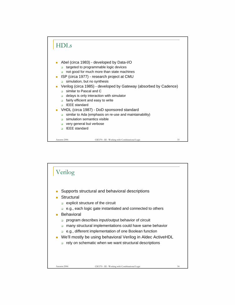
HDLs
Abel (circa 1983) - developed by Data-I/Otargeted to programmable logic devicesnot good for much more than state machines
ISP (circa 1977) - research project at CMUsimulation, but no synthesis
Verilog (circa 1985) - developed by Gateway (absorbed by Cadence)similar to Pascal and Cdelays is only interaction with simulatorfairly efficient and easy to writeIEEE standard
VHDL (circa 1987) - DoD sponsored standardsimilar to Ada (emphasis on re-use and maintainability)simulation semantics visiblevery general but verboseIEEE standard
Autumn 2006 CSE370 - III - Working with Combinational Logic 34
Verilog
Supports structural and behavioral descriptionsStructural
explicit structure of the circuite.g., each logic gate instantiated and connected to others
Behavioralprogram describes input/output behavior of circuitmany structural implementations could have same behaviore.g., different implementation of one Boolean function
We’ll mostly be using behavioral Verilog in Aldec ActiveHDLrely on schematic when we want structural descriptions

Autumn 2006 CSE370 - III - Working with Combinational Logic 35
module xor_gate (out, a, b);input a, b;output out;wire abar, bbar, t1, t2;
inverter invA (abar, a);inverter invB (bbar, b);and_gate and1 (t1, a, bbar);and_gate and2 (t2, b, abar);or_gate or1 (out, t1, t2);
endmodule
Structural model
Autumn 2006 CSE370 - III - Working with Combinational Logic 36
module xor_gate (out, a, b);input a, b;output out;reg out;
assign #6 out = a ^ b;
endmodule
Simple behavioral model
Continuous assignment
delay from input changeto output change
simulation register -keeps track ofvalue of signal

Autumn 2006 CSE370 - III - Working with Combinational Logic 37
module xor_gate (out, a, b);input a, b;output out;reg out;
always @(a or b) begin#6 out = a ^ b;
end
endmodule
Simple behavioral model
always block
specifies when block is executed ie. triggered by which signals
Autumn 2006 CSE370 - III - Working with Combinational Logic 38
module testbench (x, y);output x, y;reg [1:0] cnt;
initial begincnt = 0;repeat (4) begin
#10 cnt = cnt + 1;$display ("@ time=%d, x=%b, y=%b, cnt=%b",
$time, x, y, cnt); end#10 $finish;
end
assign x = cnt[1];assign y = cnt[0];
endmodule
Driving a simulation through a “testbench”
2-bit vector
initial block executed only once at startof simulation
directive to stop simulation
print to a console

Autumn 2006 CSE370 - III - Working with Combinational Logic 39
Complete simulation
Instantiate stimulus component and device to test in a schematic
a
b
ztest-bench
xy
Autumn 2006 CSE370 - III - Working with Combinational Logic 40
module Compare1 (Equal, Alarger, Blarger, A, B);input A, B;output Equal, Alarger, Blarger;
assign #5 Equal = (A & B) | (~A & ~B);assign #3 Alarger = (A & ~B);assign #3 Blarger = (~A & B);
endmodule
Comparator example

Autumn 2006 CSE370 - III - Working with Combinational Logic 41
Hardware description languages vs. programming languages
Program structureinstantiation of multiple components of the same typespecify interconnections between modules via schematichierarchy of modules (only leaves can be HDL in Aldec ActiveHDL)
Assignmentcontinuous assignment (logic always computes)propagation delay (computation takes time)timing of signals is important (when does computation have its effect)
Data structuressize explicitly spelled out - no dynamic structures no pointers
Parallelismhardware is naturally parallel (must support multiple threads)assignments can occur in parallel (not just sequentially)
Autumn 2006 CSE370 - III - Working with Combinational Logic 42
Hardware description languages and combinational logic
Modules - specification of inputs, outputs, bidirectional, and internal signalsContinuous assignment - a gate’s output is a function of its inputs at all times (doesn’t need to wait to be "called")Propagation delay- concept of time and delay in input affecting gate outputComposition - connecting modules together with wiresHierarchy - modules encapsulate functional blocks
Autumn 2006 CSE370 - III - Working with Combinational Logic 43
Working with combinational logic summary
Design problemsfilling in truth tablesincompletely specified functionssimplifying two-level logic
Realizing two-level logicNAND and NOR networksnetworks of Boolean functions and their time behavior
Time behaviorHardware description languagesLater
combinational logic technologiesmore design case studies