working dimensions - broughton plant hire website/power... · battery cells. the electrolyte should...
TRANSCRIPT

Power Towers Ltd, West House, West Avenue, Wigston, Leicester LE18 2FB, United Kingdom, Tel: +44 (0)116 200 1757, Fax: +44 (0)116 284 9243
[email protected] | www.powertowers.com
Working Dimensions Maximum Working Height 5.10 m Maximum Platform Height 3.10 m Platform Dimensions 1.52 x 0.75 m Working Footprint 1.62 x 0.78 m Safe Working Load 250 kgs No. Persons 1 Maximum Manual Force 200 n Max. Gradient for Operation 0° Max. Wind Force 0 MPH Indoor Only Manual Push Force on Level Ground 9 kgs Maximum Total Weight Inc Payload 592kgs Maximum Castor Point Load 2.9 KN
Closed Dimensions Length 1.62 m Width 0.78 m Height 1.85 m Weight 342 kgs Power Source Standard 12v DC Electric Motor IP55 Or 240v AC Electric Motor 13A Supply Or 110v AC Electric Motor 16A Supply Battery 12v 105A Traction Deep Cycle Battery Charger Specification Input Voltage 90-265v A.C. Frequency 45-65 Hz Output 12v DC, 7A Emission EN 55014N, EN 61000
2
Content
Page
3 – 4 Battery Maintenance
5 Battery Charging Fault
6 How to Change the Oil in the Hydraulic System
7 Check Operation of Emergency Lowering Valve 8 Repair a Faulty Emergency Cylinder Valve Shaft 9 Gate Spring Mechanism
10 - 11 Inspect Main Boom Pivot Pins
12 – 13 Replacing the lift Cylinder.
14 – 15 Replace a Main Pivot Pin
16 Castor and Wheel Maintenance
17 Replacement of Castor Wheel
18 Replace a Real Wheel
Battery Maintenance
Please ensure, the unit is isolated and you use the correct PPE as indicated.

3
Check the electrolyte level in each of the battery cells. The electrolyte should be covering the plates by one to two millimetres
Check the connections and make sure the battery is clean
Using a hydrometer, check the specific gravity of each cell in the battery. The hydrometer should read between 1.28 and 1.285, and all cells should be equal.

4
Use a voltmeter to check the voltage. The reading should be approximately 13 volts.

5
Battery Charging Fault
Please ensure, the unit is isolated and you use the correct PPE as indicated.
Ensure the isolator switch is set to the ‘on’ position.
Check the battery charger lights when first switched on (Display Green LED On, Amber LED blinking fast is bulk load, blinking slow is absorption, on float, off storage.) If the both charger lights flash slowly, check the fuse, battery connections and then the battery condition as outlined in the chapter: ‘Battery Maintenance’.
If there are no lights on the charger, check the supply connections.

6
How to Change the Oil in the Hydraulic System
Please ensure, the unit is isolated and you use the correct PPE as indicated.
Use a syringe to empty the hydraulic reservoir.
Refill with 2.5 litres of Grade 32 mineral oil.
Elevate the machine from the ground controls to ensure the platform reaches full travel. If not add a little more oil. Please Note; Do not keep the pump running without any oil in the tank.

7
Check Operation of Emergency Lowering Valve
Please ensure, the unit is isolated and you use the correct PPE as indicated.
Elevate the platform from the ground controls, ideally to full height. Pull and twist the knurled knob on the power pack so it is locked open Press the red button on the cylinder valve.
Keep pressed until the platform is fully lowered
Please note when pressing the red button on the cylinder valve do not put your hand between the tie bar and descending boom, access the red button from underneath the tie bar
Release the button at any time to stop the movement. Keep clear of the descending structure.

8
Repair a Faulty Emergency Cylinder Valve Shaft
Please ensure, the unit is isolated and you use the correct PPE as indicated.
Locate the spindle on the cylinder
The valve spindle can become bent, preventing it from sliding into the housing correctly.
Remove the red cap. Identify the direction of the bend and, using a pair of pliers, gently straighten the bend.
Replace the red cap and ensure that the lowering valve operates correctly.

9
Gate Spring Mechanism
Please ensure, the unit is isolated and you use the correct PPE as indicated.
Offer the gate to the hinges and pass the long pivot bolt downward through the top hinge bracket. When feeding downward, slide the bolt though the spring until just before passing through the lower hinge bracket. Twist the lower arm of the spring behind the gate upright and then pass the pivot bolt through the lower hinge.
Allow the gate to close, and check that the “U” pin locates correctly in the jaw of the of the gate latch. If the “U” pin is too low, raise the pivot bolt slightly above the lower hinge and fit one or two M10 washers as required. Pass the pivot bolt all the way through the hinge plates, fit and tighten a lock nut and washer
10
Inspect Main Boom Pivot Pins
Please ensure, the unit is isolated and you use the correct PPE as indicated.
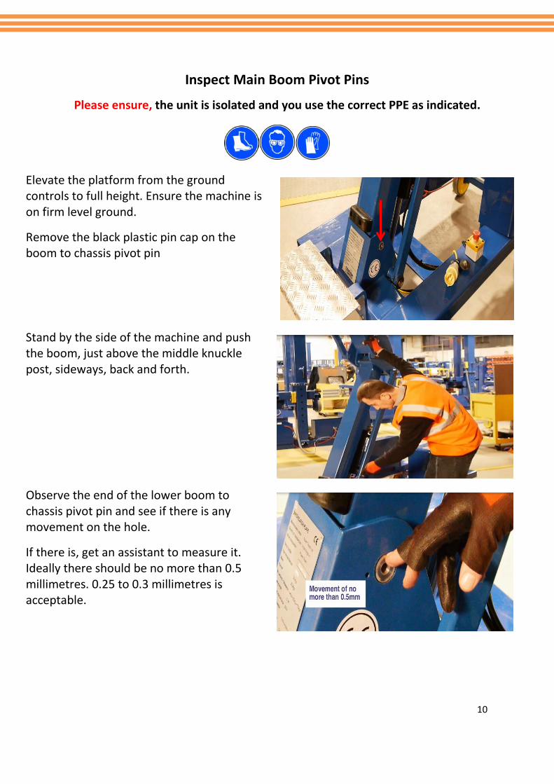
Elevate the platform from the ground controls to full height. Ensure the machine is on firm level ground.
Remove the black plastic pin cap on the boom to chassis pivot pin
Stand by the side of the machine and push the boom, just above the middle knuckle post, sideways, back and forth.
Observe the end of the lower boom to chassis pivot pin and see if there is any movement on the hole.
If there is, get an assistant to measure it. Ideally there should be no more than 0.5 millimetres. 0.25 to 0.3 millimetres is acceptable.

11
If the movement is above the tolerance, then replace the pin use a small amount of Loctite 648 when replacing the plastic pin caps
12
Replacing the Lift Cylinder
Please ensure, the unit is isolated and you use the correct PPE as indicated.
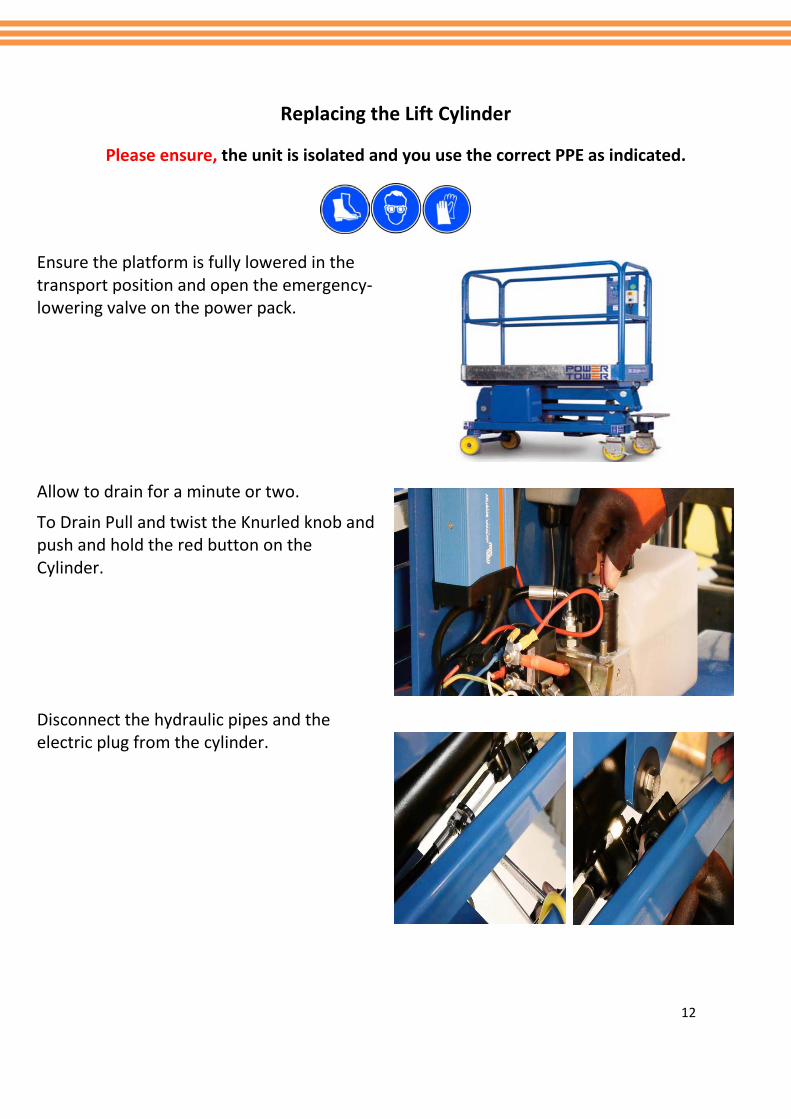
Ensure the platform is fully lowered in the transport position and open the emergency-lowering valve on the power pack.
Allow to drain for a minute or two.
To Drain Pull and twist the Knurled knob and push and hold the red button on the Cylinder.
Disconnect the hydraulic pipes and the electric plug from the cylinder.
13
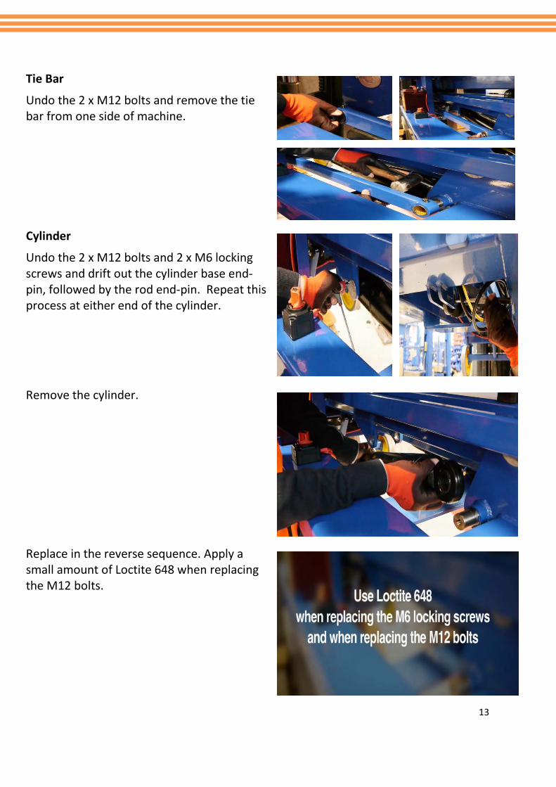
Tie Bar
Undo the 2 x M12 bolts and remove the tie bar from one side of machine.
Cylinder
Undo the 2 x M12 bolts and 2 x M6 locking screws and drift out the cylinder base end-pin, followed by the rod end-pin. Repeat this process at either end of the cylinder.
Remove the cylinder.
Replace in the reverse sequence. Apply a small amount of Loctite 648 when replacing the M12 bolts.

14
Replace a Main Pivot Pin
Please ensure, the unit is isolated and you use the correct PPE as indicated.
To replace the boom pivot pin, first lower the machine to the ground. Remove the M12 bolt and plastic end cap from both sides to enable you to slide off the tie bars.
Then remove the M6 pivot locking screw and use a suitable rod (diameter 30 millimetres), or another pin, to push out the old pin.
With a new pin (part Number PT- M- 120 OR 120S), align the hole on the pin with the hole on the chassis. And tap into place with a mallet.

15
Replace the M6 pivot locking screw. Ensure to use a small amount of thread lock 648 on M6
Replace the M12 bolts and plastic end caps
Please Note ensure to use a small amount 222 thread lock on M12

16
Castor and Wheel Maintenance
Please ensure, the unit is isolated and you use the correct PPE as indicated.
Ensure the Castor bolt is torque to 55Nm, If the castor bolts are to be found to be worn then replace with PT-M-170. Again ensure this is tightened and torqued to 55Nm.
Ensure the wheel spins freely and rotates on the castor if the wheel doesn’t move freely after being tightened to the required torque then fit a spacer washer. Check for any damage, the breaking latch moves freely and the castor is not twisted.
17
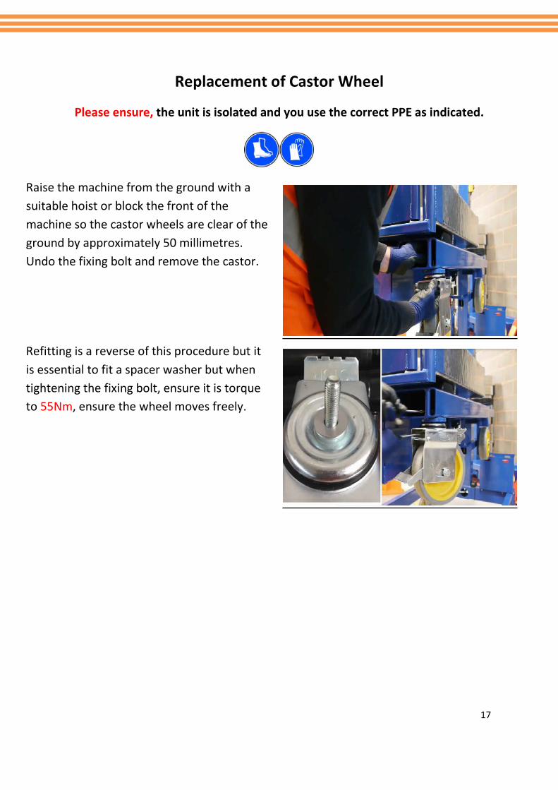
Replacement of Castor Wheel
Please ensure, the unit is isolated and you use the correct PPE as indicated.
Raise the machine from the ground with a suitable hoist or block the front of the machine so the castor wheels are clear of the ground by approximately 50 millimetres. Undo the fixing bolt and remove the castor.
Refitting is a reverse of this procedure but it is essential to fit a spacer washer but when tightening the fixing bolt, ensure it is torque to 55Nm, ensure the wheel moves freely.
18
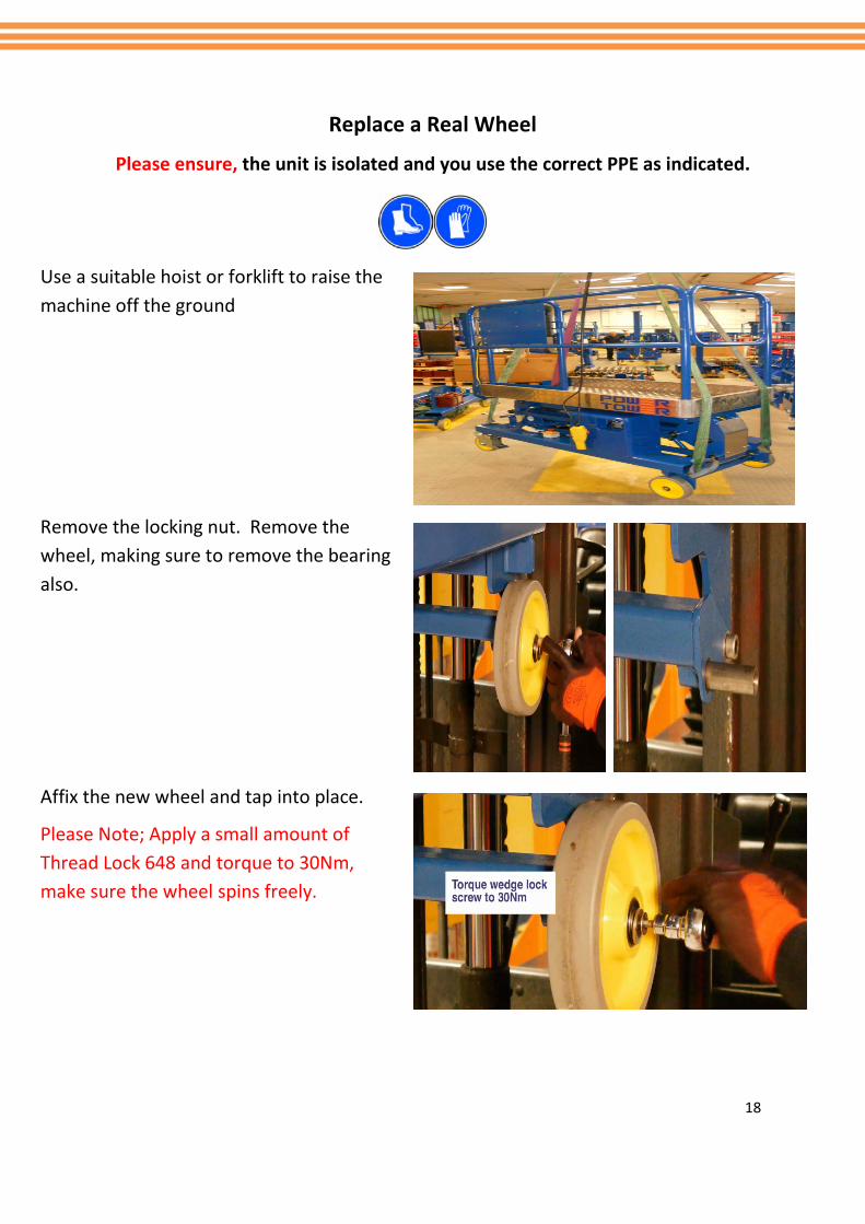
Replace a Real Wheel
Please ensure, the unit is isolated and you use the correct PPE as indicated.
Use a suitable hoist or forklift to raise the machine off the ground
Remove the locking nut. Remove the wheel, making sure to remove the bearing also.
Affix the new wheel and tap into place.
Please Note; Apply a small amount of Thread Lock 648 and torque to 30Nm, make sure the wheel spins freely.