english - broughton plant hire production and servicing of engine dri-venwelders and generating...
TRANSCRIPT

NEW MAGIC WELD
222629003 - GB1 1 0 8
18/11/08 22262M00preparato da UPTapprovato da DITE
ENGLISH


DESCRIPTION OF THE MACHINE
M0
© MOSA REV.0 - 11/08
18/1
1/08
222
62-G
B
The Engine Driven Welder is a block with an engine, an aluminium casting and a front panel. Inside the casting there are all electrical components of the machine: a permanent magnet alternator, a high frequency chopper diode bridge, an electronic control board and an electromagnet.
Main features:• D.C. welding current 150A @ 60% • Continuous regulation of the welding current with "Chopper Technology"• Suitable for basic and rutile electrodes. A reactance for cellulose electrodes is available as an option• Antistick function (small arc force)• Continuous auxiliary output 1600 W/ 230 Vdc (max. power 2000 W)• Auto idle function• Weight 34 Kg.
Electrical components of the machine:• Permanent magnet alternator: the alternator has 2 galvanically separated windings, one for welding
and the other for the auxiliary output.• Auto idle solenoid: an electromagnet inside the aluminium casting is supplied at no load only and
forces the engine speed at minimum (2000 rpm). When the load is present, welding or auxiliary output, the electromagnet is not supplied any more and the engine speed goes to the maximum (4000 rpm rated open circuit).
• High frequency chopper diode bridge: it regulates the welding current using the “Chopper Techno-logy”, which chops the welding D.C. current at high frequency.
• Hall sensor: it measures with high precision the welding current and it’s completely isolated from the welding circuit.
• Reactance for cellulose electrodes (optional).• PWM control board: this single board controls the welding process, the auxiliary current and the elec-
tromagnet for the engine accelerator. Three integrated circuits PWM type (Pulse Width Modulation) have been used. The use of these PWM’s not only for the welding control but also for the supply control of the electromagnet reduces to the minimum the wasted power on the electromagnet.
• D.C. chopped auxiliary output: the auxiliary output is chopped every 50 msec. in order to prevent damages to switches of hand tools due to arcing. This special D.C. auxiliary is suitable not only for universal hand tools with brushes, but also for those with electronic speed control. In this case the limit is that these tools can run at the maximum speed only, without possibility of speed regulation.
Auxiliary output
Fuse for auxiliary output
Welding sockets
Regulation knob for welding current
NEW MAGIC WELD


Quality systemM01
REV.4-03/12
UNI EN ISO 9001 : 2008
10/1
0/02
M01
-GB
MOSA has certified its quality system according to UNI EN ISO 9001:2008 to ensure a constant, highquality of its products. This certification covers thedesign, production and servicing of engine dri-venwelders and generating sets.
The certifying institute, ICIM, which is a member ofthe International Certification Network IQNet, awarded the official approval to MOSA after an-examination of its operations at the head office andplant in Cusago (MI), Italy.
This certification is not a point of arrival but a pledgeon the part of the entire company to maintain a levelof quality of both its products and services whichwill continue to satisfy the needs of its clients, aswell as to improve the transparency and thecom-munications regarding all the company’s activesin accordance with the official procedures and inhar-mony with the MOSA Manual of Quality.
The advantages for MOSA clients are:·Constant quality of products and services at thehigh level which the client expects;· Continuous efforts to improve the products andtheir performance at competitive conditions;
· Competent support in the solution of problems;· Information and training in the correct applicatio-nand use of the products to assure the security ofthe operator and protect the environment;
· Regular inspections by ICIM to confirm that the-requirements of the company’s quality systemand ISO 9001 are being respected.
All these advantages are guaranteed by the CER-TIFICATE OF QUALITY SYSTEM No.0192 issued by ICIM S.p.A. - Milano (Italy ) - www.icim.it

INDEX NEW MAGIC WELDM1
© MOSA REV.0 - 11/08
18/1
1/08
222
62-G
B
M 01 QUALITY SYSTEMM 1.01 COPYRIGHTM 1.1 NOTESM 1.4 CE MARKM 2 ADVICEM 2.1 SYMBOLSM 2.2 ADVICE ENGINE DRIVEN WELDERM 2.3 SYMBOLS - ABBREVIATIONS LEGENDM 2.6 INSTALLATION AND ADVICEM 2.7 INSTALLATIONM 3 UNPACKING AND TRANSPORTM 25 SET-UP FOR OPERATIONM 26 ENGINE STARTINGM 27 STOPPING THE ENGINEM 31 CONTROLSM 34... USE AS A WELDERM 37 USE AS A GENERATORM 40.2... TROUBLE-SHOOTINGM 43 MAINTENANCEM 45 STORAGE - CUST OFFM 51 TECHNICAL DATAM 55 RECOMMENDED ELECTRODESM 53 DIMENSIONSM 60 ELECTRICAL SYSTEM LEGENDEM 61-….. ELECTRICAL SYSTEM
R1 SPARE PARTS LISTAG... SPARE PARTSR1.1 REQUEST FOR ORDER SPARE PARTS

Copyright GE_, MS_, TS_, EASM
1.01© MOSA 1.0-10/02
ATTENTION
© All rights are reserved to said Company.
It is a property logo of MOSA division of B.C.S.S.p.A. All other possible logos contained in thedocumentation are registered by the respectiveowners.
The reproduction and total or partial use, in anyform and/or with any means, of thedocumentation is allowed to nobody without awritten permission by MOSA division of B.C.S.S.p.A.
To this aim is reminded the protection of the author’sright and the rights connected to the creation anddesign for communication, as provided by the lawsin force in the matter.
In no case MOSA division of B.C.S. S.p.A. will beheld responsible for any damaga, direct or indirect,in relation with the use of the given information.
MOSA division of B.C.S. S.p.A. does not take anyresponsibility about the shown information on firmsor individuals, but keeps the right to refuse servicesor information publication which it judges discutible,unright or illegal.
10/1
0/02
M1-
01-G
B
This use and maintenance manual is an importantpart of the machines in question.The assistance and maintenance personel mustkeep said manual at disposal, as well as that forthe engine and alternator (if the machine issynchronous) and all other documentation about themachine.
We advise you to pay attention to the pagesconcerning the security (see page M1.1).

INFORMATION
Dear Customer,We wish to thank you for having bought fromMOSA a high quality set.
Our sections for Technical Service and SpareParts will work at best to help you if it werenecessary.
To this purpose we advise you, for all control andoverhaul operations, to turn to the nearestauthorized Service Centre, where you will obtaina prompt and specialized intervention.
In case you do not profit on these Services andsome parts are replaced, please ask and besure that are used exclusively original MOSAparts; this to guarantee that the performancesand the initial safety prescribed by the norms inforce are re-established.
The use of non original spare parts will cancelimmediately any guarantee and Technical Ser-vice obligation from MOSA.
NOTES ABOUT THE MANUALBefore actioning the machine please read thismanual attentively. Follow the instructionscontained in it, in this way you will avoidinconveniences due to negligence, mistakes orincorrect maintenance. The manual is for qualifiedpersonnel, who knows the rules: about safety andhealth, installation and use of sets movable aswell as fixed.
You must remember that, in case you havedifficulties for use or installation or others, ourTechnical Service is always at your disposal forexplanations or interventions.
The manual for Use Maintenance and Spare Partsis an integrant part of the product. It must be keptwith care during all the life of the product.In case the machine and/or the set should beyielded to another user, this manual must alsogiven to him.Do not damage it, do not take parts away, do nottear pages and keep it in places protected fromdampness and heat.
You must take into account that some figurescontained in it want only to identify the describedparts and therefore might not correspond to themachine in your possession.
INFORMATION OF GENERAL TYPE
In the envelope given together with the machineand/or set you will find: the manual for UseMaintenance and Spare Parts, the manual foruse of the engine and the tools (if included in theequipment), the guarantee (in the countries whereit is prescribed by law).
Our products have been designed for the use ofgeneration for welding, electric and hydraulicsystem; ANY OTHER DIFFERENT USE NOTINCLUDED IN THE ONE INDICATED, relievesMOSA from the risks which could happen or,anyway, from that which was agreed when sellingthe machine; MOSA excludes any responsibilityfor damages to the machine, to the things or topersons in this case.
Our products are made in conformity with thesafety norms in force, for which it is advisable touse all these devices or information so that theuse does not bring damage to persons or things.
While working it is advisable to keep to thepersonal safety norms in force in the countries towhich the product is destined (clothing, work tools,etc.).
Do not modify for any motive parts of the machine(fastenings, holes, electric or mechanical devices,others..) if not duly authorized in writing by MOSA:the responsibility coming from any potentialintervention will fall on the executioner as in facthe becomes maker of the machine.
Notes GE_, MS_, TS_, EAS_M
1-1© MOSA 1.0-10/02
Notice: this manual does not engage MOSA,who keeps the faculty, apart the essentialcharacteristics of the model here described andillustrated, to bring betterments and modificationsto parts and accessories, without putting thismanual uptodate immediately.
10/1
0/02
M 1
-1 G
B

CE MARKM
1.4© MOSA REV.4-10/07
10/1
0/02
M1-
4 G
B
Any of our product is labelled with CE marking attesting its conformity to appliable directivesand also the fulfillment of safety requirements of the product itself; the list of these directives ispart of the declaration of conformity included in any machine standard equipment.Here below the adopted symbol:
CE marking is clearly readable and unerasable and it can be either part of the data-plate (A) orplaced as a sticker near the data-plate (B)
A B
Furthermore, on each model it is shown the noise level value; the symbol used is the following:
The indication is shown in a clear, readable and indeleble way on a sticker.

18/1
1/08
222
62-G
B
Technical dataM
1.5© MOSA REV.0 - 11/08
Technical data NEW MAGIC WELDD.C. WELDING
Current range, continuous 30 - 150AOpen circuit voltage 40-65VDuty cycle 150 A - 60%
D.C. GENERATIONSingle-phase output (max) 2 kW / 230 V / 8.7 ASingle-phase output (continuous) 1.6 kW / 230 V / 6.9 ASingle-phase output (max) (optional) 1.5 kW / 110 V / 13.6 ASingle-phase output (continuous) (optional) 1.2 kW / 110 V / 10.9 A
ALTERNATOR Self-excited, self-regulated, brushlessType permanent magnet, three-phaseInsulating class H
ENGINEMark / Model HONDA / GX 200
Type / Cooling system Gasoline 4-stroke / AirCylinders / Displacement 1 / 196 cm3
Output max 5 kW (6.8 HP)Speed 4000 rpmFuel consumption 313 g/kWhEngine oil capacity 0.6 lStarter recoil
GENERAL SPECIFICATIONSTank capacity 3.6 lRunning time (at duty cycle 60%) 3.5 hProtection IP 23Dimensions max. on base Lxlxh * 430x375x470Weight (dry) * 34 KgNoise level 99 LWA (74 dB (A) - 7 m)* Dimensions and weight are inclusive of all parts.
NEW MAGIC WELD
POWERDeclared power according to ISO 3046-1 (temperature 25°C, 30% relative hummidity, altitude 100 m above sea level).It’s admitted overload of 10% each hour every 12 h.In an approximative way one reduces: of 1% every 100 m altitude and of 2.5% for every 5°C above 25°C.
ACOUSTIC POWER LEVELATTENTION: The concrete risk due to the machine depends on the conditions in which it is used. Therefore, it is up to the end-user and under his direct responsibility to make a correct evaluation of the same risk and to adopt specific precautions (forinstance, adopting a I.P.D. -Individual Protection Device)
Acoustic Noise Level (LWA) - Measure Unit dB(A): it stands for acoustic noise released in a certain delay of time. This is not
submitted to the distance of measurement.Acoustic Pressure (Lp) - Measure Unit dB(A): it measures the pressure originated by sound waves emission. Its valuechanges in proportion to the distance of measurement.The here below table shows examples of acoustic pressure (Lp) at different distances from a machine with Acoustic NoiseLevel (LWA) of 95 dB(A)
Lp a 1 meter = 95 dB(A) - 8 dB(A) = 87 dB(A) Lp a 7 meters = 95 dB(A) - 25 dB(A) = 70 dB(A)Lp a 4 meters = 95 dB(A) - 20 dB(A) = 75 dB(A) Lp a 10 meters = 95 dB(A) - 28 dB(A) = 67 dB(A)
PLEASE NOTE: the symbol when with acoustic noise values, indicates that the device respects noise emission limitsaccording to 2000/14/CE directive.
2000 / 14 / CE

ADVICE NEW MAGIC WELDMAGIC WELD 200
M2
© MOSA REV.0 - 11/08
18/1
1/08
222
62-G
B
ATTENTION
NOTE
IMPORTANT
CAUTION
WARNING
DANGEROUS
FIRST AID. In case the operator shold be sprayed by accident, from corrosive liquids a/o hot toxic gas or whatever event which may cause serious injuries or death, predispose the first aid in accordance with the ruling labour accident standards or of local instructions.
FIRE PREVENTION. In case the working zone,for whatsoever cause goes on fire with flames liable to cause severe wounds or death, follow the first aid as described by the ruling norms or local ones.
This heading warns of an immediate danger for persons as well for things. Not following the advice can result in serious injury or death.
This heading warns of situations which could result in injury for persons or damage to things.
To this advice can appear a danger for persons as well as for things, for which can appear situations bringing material damage to things.
The installation and the general advice concerning the operations, are finalized to the correct use of the ma-chine, in the place where it is used as generator group and/or welder.
!
- Advice to the User about the safety:
N.B.: The information contained in the manual can be changed without notice. Potential damages caused in relation to the use of these instructions will not be considered because these are
only indicative. Remember that the non observance of the indications reported by us might cause damage to persons or things. It is understood, that local dispositions and/or laws must be respected.
Skin contactEyes contactIngestionSuction of liquids from lungsInhalation
Wash with water and soapIrrigate with plenty of water, if the irritation persists contact a specialistDo not induce vomit as to avoid the intake of vomit into the lungs, send for a doctorIf you suppose that vomit has entered the lungs (as in case of spontaneous vomit) take the subject to the hospital with the utmost urgencyIn case of exposure to high concentration of vapours take immediately to a non polluted zone the person involved
AppropriatedNot to be usedOther indications
Particular protectionUseful warnings
EXTINCTION MEANSCarbonate anhydride (or carbon dioxyde) powder, foam, nebulized waterAvoid the use of water jetsCover eventual shedding not on fire with foam or sand, use water jets to cool off the surfaces close to the fireWear an autorespiratory mask when heavy smoke is presentAvoid, by appropriate means to have oil sprays over metallic hot surfaces or over electric contacts (switches,plugs,etc.). In case of oil sprinkling from pressure circuits, keep in mind that the inflamability point is very low.
!
!
!
!
!
!
These headings refer to information which will assis you in the correct use of the machine and/or accessories.

SYMBOLS NEW MAGIC WELDMAGIC WELD 200
M2.1
© MOSA REV.0 - 11/08
18/1
1/08
222
62-G
B
STOP - Read absolutely and be duly attentive
HIGH VOLTAGE - Attention High Voltage.There can be parts in voltage, dangerous to touch. The non observance of the advice implies life danger.
FIRE - Danger of flame or fire. If the advice is not respected fires can happen.
HEAT - Hot surfaces. If the advice is not respected burns or damage to things can be caused.
EXPLOSION - Explosive material or danger of explosion. in general. If the advice is not respected there can be explosions.
WATER - Danger of shortcircuit. If the advice is not respected fires or damage to persons can be caused.
SMOKING - The cigarette can cause fire or explosion. If the advice is not respected fires or explosions can be caused.
WRENCH - Use of the tools. If the advice is not respected damage can be caused to things and even to persons.
ACCES FORBIDDEN to non authorizad peap-le.
SYMBOLS IN THIS MANUAL
- The symbols used in this manual are designed to call your attention to important aspects of the operation of the machine as well as potential hazards and dangers for persons and things.
This symbol is used to draw your attention to the fact that the welder is being used correctly and that the machine or equipment used operates perfectly.
Use only with safety clothing - It is compulsory to use the personal pro-tection means given in equipment.
Use with safe materials only - Never use water to put out fires on electrical equipment
Use only with non inserted voltage - It is prohibited to make interventions before having disinserted the voltage.
No smoking - It is prohibited to smoke while filling the tank with fuel.
Do not refuel - Do not refuel when the engine is hot.
Switch off the engine prior to refuelling.
Fire - Fuel can cause fires.
Use only with safety protections - It is advisable to use all protections while shifting the machine.
Use only with safety protections -It is advisable to use protections suitable for the different daily checking works.and/or of maintenance.
Exhaust gases - Exhaust gases from the engine can kill.
Petrol vapours - Petrol vapours cause fires and can seriously damage your health.
Moving parts - Moving parts are dangerous. Avoid touching any moving parts with your hands or fingers. Never wear loose clothing which may get trapped by
moving parts.

ADVICE ENGINE DRIVEN WELDER NEW MAGIC WELDMAGIC WELD 200
M2.2
© MOSA REV.0 - 11/08
18/1
1/08
222
62-G
B
ADVICE BEFORE USEThe operator of the welder is responsible for the security of the people who work with the welder and for those in the vicinity.The security measures must satisfy the rules and regulations for engine driven welders.The information given below is in addition to the local security norms.
Do not touch any bare wires, leads or contacts as they may be live and there is danger of electric shock which can cause death or serious burns. The electrode and welding cables, etc. are live when the unit is operating.
Do not touch any electrical parts or the electrode while standing in water or with wet hands, feet or clothes.
Insulate yourself from the work surface while welding. Use carpets or other insulating materials to avoid physical contact with the work surface and the floor.
Do not wind cables around the body.Always wear dry, insulating glovers, without holes, and body protection.
Estimate possible electromagnetic problems in the work area taking into account the following indi-cations:
Telephonic wirings and/or of communication, check wirings and so on, in the immediate vicinity.Radio and television receptors and transmettors.Computer and other checking devices.Critical devices for safety and/or for industrial checks.Peapol who, for instance, use pace-maker, hearing-aid for deaf or something and else.Devices used for rating and measuring.The immunity of other devices in the operation area of the welder. Make sure that other used devices
are compatible. If it is the case, provide other additional measures of protection.The daily duration of the welding time.It is forbidden to weld in rooms containing explosive gases.
Keep flamable material away from the welding area.
Do not weld on containers which contain flamable material.Do not weld near refuelling areas.Do not weld on easily flamable surfaces.Protect face and eyes (protective mask with suitable dark lens and side screens),
ears and body (non-flamable protective clothers).Avoid inhaling fumes by providing a ventilation system or, if not possible, use an approved air breather
Do not work in closed areas where there is no fresh air flow.
Do not use the welder to defrost (thaw) pipes.
Use ear protections if the noise level is high.
DANGEROUSArc welders can be dangerous. Protect yourself and others from any possible risks which may cause death or serious injury.!

SYMBOLS - ABBREVIATIONS LEGEND NEW MAGIC WELDM
2.3© MOSA REV.0 - 11/08
18/1
1/08
222
62-G
B
Equipment and optional
Permanent magnet alternator
Gene ra-tion
2000 / 14 / CE
+ -
~
°C: temperature Celsius grades A: Ampere B: pretrol C.A.(c.a.): alternating current C.C.(c.c.): direct current cc: cm³ (volume) CE: European norm conformity CF: special for pipe welding D: GFI F: Fuseg/kwh: grams/kilowatt hour (engine consumption)GMP: permanent magnet alternator Hz: frequency I: single-phase auxiliary generation (symbol 1~)IP: protection grads for electric devices against acess to dangerous parts according to the IEC 529 norm (Internal Protection)
kg: kilogram (mass) K: welding cables setkVA: kilovolt amperekW: kilowatt (engine power)kWh: kilowatt hour (energy)Lwa: maximum acoustic (power level) according to the regulations in forcemm: millimeter (length) (measure) S: symbol of EN 60974-1 T: thermic switchV: Volt
PAR600
Single-phase1 ~
Engine
Weldingcontrol
Optionals
ConformityCE
EECSound power
conformityEN 60974-1conformity
Variousnews
Information
Users'manual
Aircooling
Socket 230/110/48V EEC
Welding cur-rent electr. regulation
Gasolineengine
Manualrecoil
Arccontrol
Fuse
Welding withcovered electrode
Socket230V Schuko
Ground con-nection point
Engine shutdown (oil)
A.C.
Plus MinusD.C.
Options onrequest
Standardequipment
MaintenanceTime
Central lifting eye
Weldingcables
Various

INSTALLATION AND ADVICE NEW MAGIC WELDMAGIC WELD 200
M2.6
© MOSA REV.0 - 11/08
18/1
1/08
222
62-G
B
INSTALLATION AND ADVICE BEFORE USE Use in open space, air swept or vent exhaust gases,
which contain the deathly carbone oxyde, far from the work area.
POSITIONPlace the machine on a level surface at a distance of at least 1,5 m from buildings or other plants.
Check that the air gets changed completely and the hot air sent out does not come back inside the set so as to cause a dangerous increase of the temperature.
Make sure that the machine does not move during the work: block it possibly with tools and/or devices made to this purpose.
MOVES OF THE MACHINE At any move check that the engine is off, that there
are no connections with cables which impede the moves.
PLACE OF THE MACHINE AND/OR EQUIPMENTS
10°
10° = 20° max
10°
10° = 20° max
1,5 m
1,5 m
1,5m
GAS DI SCARICO
Maximum leaning of the machine (in case of dislevel)
EXHAUST OUTPUT
ATTENTION!For a safer use from the operator DO NOT fit the machine in locations with high risk of flood Please do not use the machine in weather conditions which are beyond IP protection shown both in the data plate and on page named “technical data” in this same manual.

NEW MAGIC WELDM
2.7© MOSA REV.O-11/08
18/1
1/08
222
62-I
InstallazioneInstallationInstallation
LuftzirkulationInstalación

UNPACKING AND TRANSPORT NEW MAGIC WELDM3
© MOSA REV.0 - 11/08
18/1
1/08
222
62-G
B
NOTE
Be sure that the lifting devices are: correctly mounted, ade-quate for the weight of the machine with it’s packaging, and conforms to local rules and regulations.When receiving the goods make sure that the product has not suffered damage during the transport, that there has not been rough handling or taking away of parts contained inside the packing or in the set.
In case you find damages, rough handling or absence of parts (envelopes, manuals, etc.), we advise you to inform immediately our Technical Service.
For eliminating the packing materials, the User must keep to the norms in force in his country.
1) Take the machine (C) out of the shipment packing. Take out of the envelope (A) the user’s manual (B).
2) Fit the handle as shown in the instructions (fitting: screws and spanner are supplied).
3) Read: the user’s manual (B), the plates fixed on the machine, the data plate.
2
B
A1
C
In case you should transport or move the machine, keep to the instructions as per the figures.Be sure that the lifting devices are: correctly mounted, adequate for the weight of the machine with it’s packaging, and conform to local rules and regulations.Only authorized persons involved in the transport of the machine should be in the area of movement.
!
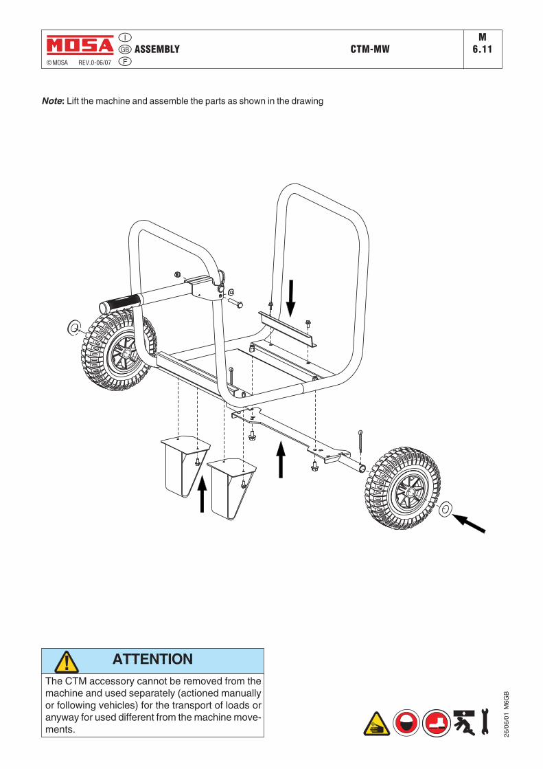
ASSEMBLY CTM-MW© MOSA REV.0-06/07
M6.11
26/0
6/01
M6G
B
Note: Lift the machine and assemble the parts as shown in the drawing
The CTM accessory cannot be removed from themachine and used separately (actioned manuallyor following vehicles) for the transport of loads oranyway for used different from the machine move-ments.
ATTENTION

Set-up for operation M25
© MOSA REV.0 - 11/08
18/1
1/08
222
62-G
B
LUBRICANT
Please refer to the motor operating manual for the recommended viscosity.
RECOMMENDED OILMOSA recommends selecting AGIP engine oil.Refer to the label on the motor for the recommended products.
To check the oil level:1. Remove the oil-fill tap (24) and clean the dip-stick
(23). 2. Insert the dip-stick into the oil filler without
screwing it in.3. If the oil level is low, fill with recommended oil up
to the top of the oil filler
Oil fill tap / dip-stick
Upper oil level
MOTORS WITH OIL ALERT DEVICE
The “Oil Alert” system is designed to prevent dama-ge to the motor due to an insufficient quantity of oil in the cup. This system automatically shuts off the motor before the oil level falls below the safety limit.If the motor does not start up again after shutting itself off, check the oil level.
FUEL
ATTENTION!Gasoline is highly flammable. Refuel with motor shut off in a flat surfaced well-venti-lated area. Do not refuel in the presence of flames. Avoid spilling fuel.
Any eventual spilled fuel and fumes are flammable. Clean any dispersions of fuel before starting up the motor.
AIR FILTERCheck that the dry air filter is correctly installed and that there are no leaks around the filter which could lead to infiltrations of non-filtered air to the inside of the motor.
WARNINGDo not use the machine if it is not in good
technical condition The machine must be in good working order
before being used. Defects, especially those which regard the safety of the machine, must be repaired before using the machine.
Do not use without protective devices provided Removing or disabling protective devices on the
machine is prohibited.
!
NEW MAGIC WELDMAGIC WELD 200
Fill the tank with gasoline for automobiles (prefe-rably lead free or with low lead content in order to reduce deposits in the combustion chamber to a minimum).
For further details on the type of gasoline to use, see the motor operating manual supplied.Do not fill the tank completely; leave a space of approx. 10 mm between the fuel level and the wall of the tank to allow for expansion.

Engine starting M
26© MOSA REV.0 - 11/08
18/1
1/08
222
62-G
B
check daily
Do not alter the primary conditions of regula-tion and do not touch the sealed parts.
NOTE!
1. Turn the fuel cock (87) to ON.
FUEL COCK
2. Switch the choke control (66) to CLOSE
N.B.: Do not use the air valve if the motor is hot or the air temperature is too high.
CHOKE LEVER
CLOSE
CLOSE
3. Turn the engine switch (28) to the ON position
ENGINE SWITCH
STARTER GRIP
Lightly pull the start-up knob (73) until meeting resistance, then pull decisively.
ATTENTION:
Allow the start-up knob to re-enter slowly, avoiding having it knock against the motor and thereby damaging the start-up system.
4. When the engine is started the machine re-aches maximum engine speed immediately (4000 rpm) for 6/7 seconds, after which the engine speed automatically decreases to minimum (2000 rpm). The minimum is set by the solenoid which acts on the accelerator lever.
5. The engine reaches maximum speed only when current is drawn in welding or auxiliary power mode.
NEW MAGIC WELDMAGIC WELD 200

Stopping the engine© MOSA REV.0 - 11/08
18/1
1/08
222
62-G
B
Before stopping the engine it is compulsory:
- Disconnect or close any power load connected to the system’s auxiliary generation.
- Interrupt welding.
To shut down the motor:
For shut down the motor in case of emergency, turn the motor switch (28) to OFF. In normal conditions, wait for the engine to reach minimum speed automatically 6/7 seconds after the load has been excluded. Turn the engine in these conditions for a few minutes so that it can cool down and then turn the engine switch (28) to OFF.
Turn the fuel valve to the OFF position.
ENGINE SWITCH
FUEL VALVE
NEW MAGIC WELDMAGIC WELD 200
M27

ComandiControlsMandos© MOSA REV.O-11/08
18/1
1/08
222
62-I
Commandes
Pos. Descrizione Description Description9
10121522232426272831667387FT
Tomas de soldadura (+)Tomas de soldadura (-)Toma de puesta a tierraToma de corriente en c.cFiltro aire motorAguja nivel aceite motorTapón llenado aceite motorTapón depósitoSilenciador de descargaMando stopTapón vaciado aceite motorPulsador ChokeMando manual arranqueGrifo de combustibleFisibleRegulador corr. de soldadura
Welding sockets (+)Welding sockets (-)Earth terminald.c. socketEngine air filterOil level dipstickEngine oil reservoir capFuel tank capMufflerStop controlOil drain tapChoke buttonStarting push buttonFuel cockFuseWelding current regulator
Prises de soudage (+)Prises de soudage (-)Prise de mise à terrePrises de courant en c.c.Filtre air moteurJauge niveau huile moteurBouchon remplissage huile moteurBouchon réservoirSilencieux d’échappementCommande stopBouchon décharge huile moteurBouton ChokeCommande manuelle démarrageRobinet de l'essenceFusibleRégulateur courant soudage
Prese di saldatura (+)Prese di saldatura (-)Presa di messa a terraPresa di corrente in c.c.Filtro aria motoreAsta livello olio motoreTappo caricamento olio motoreTappo serbatoioSilenziatore di scaricoComando stopTappo scarico olio motoreComando chokeComando manuale avviamentoRubinetto carburanteFusibileRegolatore corrente di saldatura
Descripción
F M31
F 15 T 9 10
12
22 27 26
73 31 23-2428
87
66
NEW MAGIC WELD

Use as a welderM34
© MOSA REV.0 - 11/08
18/1
1/08
222
62-G
B
Areas for which access by non-authorized personnel is forbidden are:- the control panel (at the front) - the endo-thermic motor discharge.
WARNING!
PUSH ANDTWIST
CONNECT WELDING CABLES
Insert the welding cable plugs completely in the sockets, turning clockwise to lock them in place.Connect the earth clamp to the negative pole
and the electrode holder to the positive.
Pay attention to the two polarities on the welding circuit, which must not come into electrical contact with each other.
- Carefully tighten the output cables to the bushings; if loose, they can cause problems of overheating and damage the bushings, cables, etc.
- Make certain the grounding pincer is connec-ted as near as possible to the work station.
ATTENTION!To reduce the risk of electromagnetic interfe-rence, keep the welding cable length short and keep them on or near the ground. If possible, welding operations should not be done near sensitive electronic devices. If interference continues to occur, adopt additional measures: shift the group, use shielded cables, line filters, shield the entire work area.If the above solutions do not suffice, consult our Technical Servicing Department.
ADJUSTING THE WELDING CURRENT
The welding current is regulated by turning knob “T” continuously. If set to the minimum (turned fully in an anticlockwise direction) it provides a current of approximately 30 A; if set to the maximum (turned fully in a clockwise direction) it gives a maximum current of approximately 150A.
RECOMMENDED ELECTRODES
All the electrodes on the market can be used, however for cellulose electrodes we recom-mend Magic Weld with added reactor.
NEW MAGIC WELD

Use as a welder© MOSA REV.0 - 11/08
18/1
1/08
222
62-G
B
AUTO IDLE
OperationWhen the engine is switched on it immediately reaches a maximum speed of 4000 rpm for ap-proximately 6/7 seconds for easy start up, after which it automatically decreases and idles at 2000 rpm. It remains at this speed until current is drawn when set to weld or auxiliary power.When set to weld mode the machine reaches maximum engine speed as soon as there is mi-nimum contact between the tip of the electrode and the piece to be welded and also when set to generation drawing a minimum of 250 – 300 WThe machine returns to minimum 6/7 seconds later if power is not drawn during welding or generation.
Checking and adjusting idling speed- Check idling speed when COLD;- When the engine is switched on it reaches ma-ximum speed; after 6/7 seconds it decreases automatically to idle. Check the speed when the engine idles;
- The idling speed corresponds to 33-35 Vdc (only for Italy 42-45 Vdc) at the welding sockets or the equivalent at 2000-2200 rpm.
Minimum welding voltage TOO LOW- From Fig. 1 proceed as follows:• when the machine idles (engine cold)• Keep pin A locked (8 mm spanner) and un-
screw nut B (7 mm spanner)• Again with pin A locked, turn nut C clockwi-
se (7 mm spanner) 1 - 3 mm: The more it is extended the more the idle speed increases
• Tighten nut B on pin A and check the idling speed.
Minimum welding voltage TOO HIGH- From Fig. 1 proceed as follows:• When the machine idles (engine cold)• tKeep pin A locked (8 mm spanner) and un-
screw nut B 1-3 mm (7 mm spanner)• Again with pin A locked, turn nut C anticlockwi-
se (7 mm spanner) until nut B touches pin A• Tighten nut B against pin A and check that the
idling speed is correct.
Adjusting the maximum engine speed
FIG. 1
FIG. 2
To check that the maximum engine speed is correct simply measure the welding voltage (under no-load conditions) at maximum engine speed which must be 49-51 V (only for Italy 66-68 Vdc).Turn screw (A) to adjust the engine speed Fig. 2. Turning the screw clockwise increases the idling speed , screwing it anticlockwise decreases the maximum engine speed.
M34.1NEW MAGIC WELD

Checking and adjusting the maximum welding current© MOSA REV.0 - 11/08
18/1
1/08
222
62-G
B
dal p
onte
cho
pper
from
cho
pper
wel
ding
brid
geda
l sen
sore
di c
orre
nte
from
cur
rent
sen
sor
taratura corrente max. di sald. (*)welding max. current adjustment (*)
dall'alternatorefrom alternator
dai ponti ausiliarifrom aux. bridges
dal frontalefrom frontal
dal solenoidefrom solenoid
NEW MAGIC WELD M
34.2
So
l.1
So
l.2 Si
Su
Ri
RuYTi
Tu
21
14
13
7 8
1 2
11
12 2
1
YT
R
S
S
R
T
ON
OFF
*) Tutte le volte che viene sostituita o la scheda o il sensore di corrente è necessario procedere ad una verifica della massima corrente di saldatura e eventualmente procedere ad una sua taratura nel se-guente modo:- Lasciare fissato il frontale solo con la vite centrale inferiore e non stringerla in modo che il frontale nella
sua parte superiore rimanga staccato di circa 7-8 cm.- Ruotare il trimmer sulla scheda tutto in senso antiorario.- Porre i dip switch secondo la figura- Verificare che al minimo del potenziometro corrisponda il minimo della manopola.- Porre la manopola di saldatura al minimo e avviare il motore. Lasciare che la macchina vada al
minimo poi fare un corto circuito tra il + e - tramite i cavi di saldatura.- Ruotar e la manopola di saldatura al massimo.- Ruotare lentamente il trimmer in senso orario affinché la corrente di saldatura arrivi a 140A.
*) Every time either the board or the current sensor is changed, it is necessary to check the max. welding current and, if it is the case, to set it as follows:
- Keep the front panel fixed with its lower central screw and don't tight it, so that the front panel in its upper part can have a gap of 7-8 cm.
- Rotate the trimmer on the board fully anticlockwise.- Put the dip switch as drawing- Check that to the minimum of the potentiometer corrisponds the minimum of the knob.- Put the welding knob to the minimum and start the engine.- Let the machine idle, then shortcircuit between the + and - welding sockets through the welding cables.- Rotate the welding knob to the maximum.- Slowly rotate the trimmer clockwise so that the welding current reaches 140 A.
Dip switch
Dip switch
Dip switch

Parallel engine driven welderM
34.3© MOSA REV.0 - 11/08
How to put two machines in parallel:
from the front panels of the machines connect the two positives welding sockets(+) between themselves and the two negative welding sockets bethween themselves.To effect the connection ask for the accessory K2X150.
ATTENTION: use fit cables and tight at the connection point.
How to proceed:- start the machine putting the two welding handles (T) in the wanted position (half of the total current);
- put in parallel with the right cables;- proceed with welding.
18/1
1/08
222
62-G
B
NEW MAGIC WELD

Use as a generator© MOSA REV.0 - 11/08
18/1
1/08
222
62-G
B
WARNING!
GENERATION IN C.C. (CONTINUOUS CUR-RENT WITH MICRO-INTERRUPTION)
Machines with three pin outlets for auxiliary supply have, at each outlet, isolated active and neutral sockets, and an earth socket. Only the earth socket is bonded to the frame of the machine.For your safety, all auxiliary equipment, exten-sion cords, appliance cords, plugs, plug sockets and appliances should be in good condition and correctly wired and connected. All earthing wi-res, qhere used, must be continuous. Extension corde with three wires should be used except for double insulated appliances.
The frame of the unit should not be connec-ted to the general mass of earth by an earth spike or by any other means, but should be isolated from earth.
Note: in line with current practice, a floating auxiliary power system is used. The auxiliary power windings are not connected to the fra-me, hence a "residual current device" is not required.
- If the generator is used to feed more complex circuits, or used in special environments, for example: building sites, it is obligatory to interpose between the socket and the loads a small distribution panel complete with electrical safeties foreseen by regulatory norms in force in matters of electrical installation.
It is absolutely forbidden to connect the unit to the public mains and/or another electrical power source.
Areas for which access by non-authorized personnel is forbidden are:- the control panel (at the front) - the endo-thermic motor discharge.
M37NEW MAGIC WELD

Trouble-shooting© MOSA REV.0 - 11/08
18/1
1/08
222
62-G
B
The motor does not start up, or starts up and then stops immediately
1) Engine switch (28) at position OFF
2) Lack of or insufficient oil in the motor
3) Faulty motor stopping device (oil-alert)
4) Lack of fuel in tank or fuel tap closed
5) Dirty or faulty spark plug
6) Cold motor
7) Other causes
1) Position switch to ON
2) Refill or top off
3) Replace
4) Refill the tank. Open the fuel tap
5) Clean or check and eventually replace
6) Hold down the CHOKE button, after start-up, for a longer period of time
7) Consult the motor Operating Ma-nual.
Problem Possible cause Solution
No current under no-load conditions in weld modeNo current under no-load
conditions in auxiliary power modeIncorrect minimum voltage
1) Use a multimeter to test that there are 3 Kohms between pins 1-2; if NOT replace the bridge
2) Replace3) Disconnect the welding and
auxiliary power cables. Use a voltmeter to check that there is 48 Vac at the outputs in weld and approximately 170 Vac in the 230 V version and 90 Vac in the 110 V version. Carry out the check when the engine idles (discon-nect one of the two wires to the solenoid)
1) Chopper welding bridge broken
2) Faulty circuit3) Faulty alternator
1) replace the fuse 10A retarded for version 230V 15A retarded for version 110V2) Use a multimeter to check the 2
single phase diode bridges on the auxiliary power
3) Replace4) Disconnect the welding and
auxiliary power cables. Use a voltmeter to check that there is 48 Vac at the outputs in weld and approximately 170 Vac in the 230 V version and 90 Vac in the 110 V version. Carry out the check when the engine idles (discon-nect one of the two wires to the solenoid).
1) Fuse open
2) Auxiliary power diode bridge broken
3) Faulty circuit4) Faulty alternator
under no-load conditions 1) Adjust the solenoid as shown on page M34.
1) Incorrect solenoid adjustment
M40.2
NEW MAGIC WELD

Trouble-shooting © MOSA REV.0 - 11/08
18/1
1/08
222
62-G
B
M40.2.1
Problem Possible cause Solution
RESISTENCE OF WINDING AT 20°CΩ (ohm) NOTE
Output in weld mode Between green / black cable Between green / red cable Between black / red cable
0,0300,0300,030
All cables of the same colour are connected in parallel
Auxiliary power outputs 230 VdcBetween the black cables: R / SBetween the black cables: R / TBetween the black cables: S / T
1,21,21,2
Auxiliary power outputs 110VdcBetween the black cables: R / SBetween the black cables: R / TBetween the black cables: S / T
1,01,01,0
Cable Y is connected to the centro stella of the three phase circuit
Cable Y is connected to cable T
1) Adjust the maximum engine spe-ed as shown on page M34.
Incorrect maximum voltage under no-load conditionsEngine always at idle speed 1) Replace
Engine always at maximum speed
1) Incorrect maximum engine speed
1) Faulty circuit
1) Replace;2) Check that the resistance of the
solenoid winding is approximately 10 ohm.
Insufficient power during welding or generation
1) Dirty petrol filter, dirty air filter, dirty carburetor. See engine instruction booklet.1) Disconnect all the outputs; 3 for
1) faulty circuit2) Faulty solenoid1) Engine
1) al ternator windings not
Irregular or inconsistent wel-ding current
insulated from earth
2) welding chopper bridge not insulated from earth
3) power cables not insulated from earth
4) faulty circuit
welding which go to the chopper bridge and 4 for auxiliary power which go to the circuit board. Use a multimeter to check the insulation of the alternator;
2) disconnect the 3 welding cables, the + and - for welding, the black wire and the connector which go to the circuit board, Use a multimeter to check that the bridge is insulated from the earth.
3) check that the cables inside the aluminium casting, are properly insulated;
4) Replace
NEW MAGIC WELD

MAINTENANCE© MOSA REV.0 - 11/08
18/1
1/08
222
62-G
B
!
!
• Maintenance and repair work should only be done by qua-lified personnel.
• Stop the engine before doing any work on the machine. If for any reason the machine must be operated while working on it, be careful not to touch rotating parts, hot surfaces, live wires, etc. which may be unprotected.
• Remove protective guards only when necessary to perform maintenance and replace them immediately after the main-tenance is completed.
• Use suitable tools and wear suitable clothes.• Do not modify the machine without prior authorization
ATTENTION
When carrying out maintenance operations be careful to avoid polluting the environment with the materials used during maintenance. Follow all local health and safety regulations.
IMPORTANT
MAINTENANCE OF THE MACHINEMaintenance refers to all operations regarding the control and replacement of mechanical and electrical parts subject to wear. In addition it refers to the control and topping up or replace-ment of fluids such as fuel, oil and the regular cleaning of the machine.
Repairs refers to the substitution of worn or damaged parts and repairs should be carried out by Authorized Service Centres.
Refer to the Engine Manufacturer’s Manual for the maintenance instructions for the engine. Periodic maintenance should be performed according to the schedule shown in this manual.
On a regular basis check that there are no obstructions in the aspiration/exhaust ducts of the alternator, the engine or the housing which could restrict the flow of cooling air.
DRY AIR FILTERReplace the air filter cartridge every 200 hours under normal conditions and every 100 hours in dusty environments.
PERMANENT MAGNET ALTERNATORNo maintenance is necessary, as the alternator has no brushes or slip rings, and there are no devices for regulation of the output.
WARNING LABELS AND DECALSCheck warning labels and decals once a year and replaced if missing or unreadable.
CABLES AND CONNECTIONSPeriodically check the condition of the cables and tighten the connections.
HOT surfacecan
hurt you
MOVINGPARTS
can injure
M43
NEW MAGIC WELDMAGIC WELD 200

STORAGE - CUST OFF© MOSA REV.0 - 11/08
18/1
1/08
222
62-G
B
M45
Have qualified personnel prepare the ma-chine for the cust-off.
STORAGE
In case the machine will not be used for more than 30 days, it should be stored in a suitable area where it is protected from the elements to prevent rusting, corrosion and other damage to the machine.
ENGINE
Run the engine until it stops from lack of fuel.
For long periods of storage, refer to the engine manufacturer’s manual.
Clean the machine carefully.
Cover the machine with a plastic cover and store in a dry place.
CUST-OFFAs cust off we intend all operations to be made, at utilizer’s care, at the end of the use of the machine.
This comprises the dismantling of the machine, the subdivision of the several components for a further reutilization or for getting rid of them, the eventual packing and transportation of the eliminated parts up to their delivery to the store, or to the bureau encharged to the cust off or to the storage office, etc.
The several operations concerning the cust off, involve the manipulation of fluids potentially dangerous such as: lubricating oil.
The dismantling of metallic parts liable to cau-se injuries or wounds, must be made wearing heavy gloves and using suitable tools.
The getting rid of the various components of the machine must be made accordingly to rules in force of law a/o local rules.
Particular attention must be paid when getting rid of: lubricating oils, inflamable liquids such as fuel.
The machine user is responsible for the obser-vance of the norms concerning the environment conditions with regard to the elimination of the machine being cust off and of all its compon-ents.
In case the machine should be cust off without any previous disassembly it is however com-pulsory to remove:
- tank fuel- engine lubricating oil
NOTE: MOSA is involved with custing off the machine only for the second hand ones, when not reparable.This, of course, after authorization.
In case of necessity for first aid and fire preven-tion, see page M2.
In the storage or cust-off operations avoid that polluting substances, liquids, exhausted
oils, etc. bring damage to people or things or can cause negative effects to surroindings, health or
safety respecting completely the laws and/or dispositions in force in the place.
! IMPORTANT
NEW MAGIC WELDMAGIC WELD 200

RECOMMENDED ELECTRODES (In accordance with A.W.S Standard) MS_, TS_M55
© MOSA 1.0-10/03
The information here below are to be intended only as indicative since the above norm is much larger.For further details please see the specific norms and/or the manufacturers of the product to be used in the weldingprocess.
RUTILE ELECTRODES: E 6013
Easily removable fluid slag, suitable foe welding in all position.Rutile electrodes weld in d.c. with both polarities (electrode holder at + or -) and in a.c..Suitable for soft steels R-38/45 kg/mm2 . Also for soft steels of lower quality.
BASIC ELECTRODES: E 7015
Basic electrrodes wels onlu in d.c. with inverse polarity (+ on the electrode holder) ; there are also types for a.c.Suitable for impure carbon steels. Weld in all position.
HIGH YIELD BASIC ELECTRODES: E 7018
The iron contained in the coating increases the quality of metal added. Good mechanical properties. Weld in all position.Electrode holder at + (inverse polarity). Wld deposit of nice aspect, also vertical. Workable; high yield.Suitable for steels with high contens of sulphur (impurities).
CELLULOSIC ELECTRODES: E 6010
Cellulosic electrodes weld only in d.c. with polarity + electrode holder - ground clamp.Special for steels run on pipes with R max 55 kg/mm2. Weld in all position. volatile slag.
ELECTRODES IDENTIFICATION ACCORDING TO A.W.S. STANDARDS
E X X Y Z2 digits: type of coatingand electric powerconditions.(see table 3)
1 digits: weldingpositions.(see table 2)
2÷3 digits: tesile strenght ofthe weld deposit.(see table 1)
symbol for"Coated
electrode"
10 Cellulose electrodes for d.c.11 Cellulose electrodes for a.c.12 Rutile electrode for d.c.13 Rutile electrode for a.c.14 High yield rutile electrodes15 Basic electrodes for d.c.16 Basic electrodes for c.a.18 High yield basic electrodes for d.c. (inverse polarity)20 Acid electrodes for flat or front position welding for
d.c. (- pole) and for a.c.24 High yield rutile electrodes for flat or front plane
position welding for d.c. and a.c.27 High yield acid electrodes for flat or front plane
position welding for d.c. (- pole) and a.c..28 High yield basic electrodes for flat or front plane
position welding for d.c. (inverse polarity)30 Extra high yield acid electrodes, extra high
penetration if required, for flat position welding onlyfor d.c. (- pole) and a.c.
N° Descrizione
Number Strenght
K.s.l. Kg/mm2
60708090
100110120
60.00070.00080.00090.000
100.000110.000120.000
424956637077
84
for all positionsfor plane and verticlfor plane posotion only
123
Table 1
Table 2 Table 3
10/1
0/03
M55
GB

© MOSA REV.O-11/08
18/1
1/08
222
62-I
M53
DimensioniDimensionsDimensions
AbmessungenDimensiones
375
430
470
510854 610
402
~566
NEW MAGIC WELD

18/1
1/08
222
62-I
NEW MAGIC WELDM60
© MOSA REV.O-11/08
A : AlternatoreF : FusibileH : Presa 230V monofaseI : Presa 110V monofaseR : Unità controllo saldaturaT : Regolatore corrente saldaturaY : Ponte diodi saldaturaF1 : Elettromagnete acceleratoreS2 : Trasmettitore livello olioF3 : Pulsante stopG3 : Bobina accensioneH3 : Candela accensioneW6 : Sensore di hall
Legenda schema elettrico Electrical system legende Legende des schemas electriques
Stromlaufplan-Referenzliste Leyenda esquema eléctrico
A: AlternatorF: FuseH: 230V 1phase socketI: 110V 1-phase socketR: Welding control PCBT: Welding current regulatorY: Welding diode bridgeF1: Acceleration solenoidS2: Oil level transmitterF3: Stop push-buttonG3: Ignition coilH3: Spark plugW6: Hall sensor
A : AlternateurF : FusibleH : Prise 230V monophaséI : Prise 110V monophaséR : Unite contrôle soudageT : Régulateur courant de soudageY : Pont diodes soudageF1 : Electro-aimant accélérateurS2 : Transmetteur niveau huileF3 : Bouton stopG3 : Bobine allumageH3 : Bougie allumageW6: Senseur de hall
A GeneratorF SicherungH Steckdose 230V 1-phasigI Steckdose 110V 1-phasigR Steuerplatine SchweißstromT SchweißstromreglerY Diodenbrücke SchweißstromF1 Elektromagnet MotordrehzahlS2 ÖlstandssensorF3 Taste StoppG3 ZündspuleH3 ZündkerzeW6 Hall-Sensor
A :AlternadorF :FusibleH :Toma 230V monofásicaI :Toma 110V monofásicaR :Unidad control soldaduraT :Regulador corriente soldaduraY :Puente diodos soldaduraF1 :Electromagnetismo aceleradorS2 :Captador nivel aceiteF3 :Pulsador stopG3 :Bobina encendidoH3 :Bujía encendidoW6 :Sensor de entrada

18/1
1/08
222
62-I
Schema elettricoElectric diagramEsquema eléctrico
NEW MAGIC WELD(110V version)
M61
© MOSA REV.O-11/08
20090-C
US
AG
O(M
I)-I
TA
LYhttp://w
ww
.mosa.it
MA
GIC
WE
LD
Wirin
gD
iagra
m22263.p
rg
22
24
0.S
.06
0-F
Lepora
ce
N.
2 Appr
ovat
o:
Esp.
Data
Dis.
Appr
.Mo
difi
ca
Deno
mina
zion
e:
Macc
hina
:Da
ta:
Prog
etto
:di
n°Pa
g.n°
2
Date
Appr
.
Appr
oved
:
Proj
ect:
Deno
mina
tion
:
Mach
ine:
Modi
fica
tion
Date
:
DaPa
g.
Alla
Pag.
ToPa
ge
From
Page
Desi
gner
:
ofn°
Desi
.
Dis.
n°:
Exp.
Page
n°
Dwg.
n°:
Dise
gnat
ore:
LaMOSA
siriserva
atermini
dilegge
laproprieta'
del
presente
disegno
con
divieto
diriprodurlo
ocomunicarlo
aterzi
senza
sua
autorizzazione.
02.0
7.2
004
-+
KE
YC
OLO
RLE
GE
ND
AC
OLO
RI
NE
RO
/BLA
CK
(R)
RO
SS
O/R
ED
(B)
(B)
Y T S R
(B)
GIA
LLO
/YE
LLO
W
(B)
(Y)
(B)
(Y)
(Y)
(B)
(Y)
(B)
(B)
(Y)
(BL
)
(BL
)B
LU
/BLU
E
(Y)
(R)(B)(B)
(R)
(BL)
+ -
~ ~ ~
-+ Z
3~
GS
AW
6
Y
F1
S2
G3
H3
ON
OF
F F3
P1
P3
P2
Sol.1
Sol.2
Si
Su
Ri
Ru
Tu
Ti
Y
12
34
56
78
91
011
12
R
T
A18.0
4.2
005
N.L
.
T
(R)
(B)
S R
+ - + -
F
15
A
11
0V
/16
A
I
Aggiu
nto
soppre
ssore
(Zenam
ic)
apr
ote
zio
ne
deiponti
dio
diausili
aria.
BA
ggiu
nto
ponticello
tra
pi n
9e
10
su
conn.
P1
(opzio
ne
Arc
-F
orc
e).
22.0
3.2
006
N.L
.
(BL)
N.L
.C
03.0
4.2
006
1K
oh
m/¼
W
Aggiu
nto
resis
tenza
1K
ohm
/¼W
nelpontic
ello
tra
pin
9e
10
su
conn.
P1.
22
Ko
hm
/2W
D27.0
6.2
006
N.L
.A
ggiu
nto
resis
tenza
22K
ohm
/2W
inpara
llelo
uscita
ponti
dio
diausila
ria.
10µH
Aggiu
nto
induttanza
10µ
Hsu
cavo
1connettore
P1.
23.0
5.2
007
N.L
.E
Aggiu
nto
reattore
(W)
F27.1
0.2
008
N.L
.
W

18/1
1/08
222
62-I
Schema elettricoElectric diagramEsquema eléctrico
NEW MAGIC WELD(EU Version)
M61.1
© MOSA REV.O-11/08
2009
0-CU
SAG
O(M
I)-IT
ALY
http
://ww
w.m
osa.
itM
AGIC
WEL
D
Wiri
ngDi
agra
m22
243.
prg
2224
3.S.
060-
CLe
pora
ceN.
2 Appr
ovat
o:
Esp.
Data
Dis.
Appr
.M
odific
a
Deno
min
azio
ne:
Mac
chin
a:Da
ta:
Prog
etto
:di
n°Pa
g.n°
2
Date
Appr
.
Appr
oved
:
Proj
ect:
Deno
min
atio
n:
Mac
hine
:
Mod
ificat
ion
Date
:
DaPa
g.
Alla
Pag.
ToPa
ge
From
Page
Desig
ner:
ofn°
Desi.
Dis.
n°:
Exp.
Page
n°
Dwg.
n°:
Dise
gnat
ore:
La
MO
SA
sirise
rva
ate
rmin
id
ile
gg
ela
pro
prie
ta'd
elp
rese
nte
dis
eg
no
co
nd
ivie
tod
irip
rod
urlo
oco
mu
nic
arlo
ate
rzise
nza
su
aa
uto
rizza
zio
ne
.
-+
T
(R)
(B)
KEY
COLO
RLE
GEN
DACO
LORI
NERO
/BLA
CK(R
)RO
SSO
/RED
(B)
(B)
Y T S R
S R
(B)
GIA
LLO
/YEL
LOW
(B)
(Y)
(B)
(Y)
(Y)
(B)
(Y)
(B)
(B)
(Y)
(BL)
(BL)
BLU/
BLUE
(BL)(Y)
(R)(B)(B)
(R)-+ Z
3~GS
A
W
+ - + -
F10
A
23
0V
/16
A
H
W6
Y
F1S2
G3
H3
ON
OFF
F3
P1
P3 P2
Sol.1
Sol.2
Si Su Ri Ru
Tu
Ti
Y
12
34
56
78
910
1112
R
A18
.04.
2005
N.L.
Aggi
unto
sopp
ress
ore
(Zen
amic)
apr
otez
ione
dei p
onti
diod
i aus
iliaria
.
02.0
7.20
04
2x15
Kohm
/2W
N.L.
BAg
giun
ton°
2re
siste
nze
da15
Kohm
/2W
inpa
ralle
lous
cita
pont
i dio
diau
silar
ia.
19.0
9.20
06
10µH
CAg
giun
toin
dutta
nza
10µH
suca
vo1
conn
etto
reP1
.23
.05.
2007
N.L.

SPARE PARTS LISTR1
© MOSA 1.0-03/00
MOSA guarantees that any request for spare parts will be satisfied.To keep the machine in full working order, when replacement of MOSA spare parts is required, always ask for genuine parts only.
When ordering the spare parts, it is recom-mended to indicate:
1) Y serial number
2) Y model of welder and/or generating set
3) u n. table
4) u n. position
5) quantity
14
/12
/98
6Q
16
M3
1
TAVOLA RICAMBI - SPARE PARTS - PIECES DE RECHANGE - ERSATZTEILE
ONOFF
START
*
VE
NULLEITERAUFMASSENULVERBONDENMETMASSA
NEUTROCONECTADOAMASA
NEUTRERACCORDEAUBATINEUTRALBONDEDTOFRAME
NEUTROCOLLEGATOAMASSA
*
6560
Hz A
1050
1555
500
300
V
ST
RS0
200
100
TR0
h
HOURMETER
I
0
EA1
2520
125
1-3 13 18 17 16 20-21-22 12
21-22-2314
11
8
2
19
15
4-5-6
EA1
12
50
Hz
50
Hz 3
EA1
4
12
TS 0000 GE
V.le Europa,59 - 20090 CUSAGO (MI) ITALY
Tel. +39-02 90352.1 - fax +39-02 90390466
0987654321
TYPE
SERIAL N°
22/0
3/00
R1G
B
The requested data are to be found on the data plate located on the machine structure, quite visible and easy to consult. Y
ABBREVIATIONS AND SYMBOLS:(EV) Whenordering,specifytheenginetypeand theauxiliaryvoltage(ER) Enginewithrecoilstarteronly(ES) Enginewithelectricstarteronly(VE) E.A.Sversiononly.(QM) Whenordering,specifythelengthinmeters(VS) Specialversiononly(SR) Byrequestonly

18/1
1/08
222
62-I
© MOSA REV.O-11/08
RicambiSpare partsPiéces de rechange
ErsatzteileTabla de recambios
AGNEW MAGIC WELD 5
1
2
(230V Version)
(110V Version)
33a
4
6
55a
(110V version)
(230V version)
7
8
9
10
11
12
13
14
15
16
1718
20
23
2422
19
21
25

18/1
1/08
222
62-I
© MOSA REV.O-11/08NEW MAGIC WELD
AG5.1
RicambiSpare partsPiéces de rechange
ErsatzteileTabla de recambios
Pos. Rev. Cod. Descr. Note 1 222406020 VENTOLA CENTRIFUGA / FAN 2 222403047 ASSIEME MOZZO/ROTORE /HUB / SHAFT ASSY 3 222413025 STATORE AVVOLTO 230 VAC / STATOR 230V Versione 230V /230V version 3a 222403025 STATORE AVVOLTO 110 VAC / STATOR 110V Versione 110V / 110V version 4 222418263 PIASTRINA FERMA CAVI 5 1270040 PONTE DIODI / DIODE BRIDGE 35A800V Versione 110V / 110V version 5a 1270070 PONTE DIODI / DIODE BRIDGE Versione 230V / 230V version 6 222422200 MOTORE HONDA GX200T - EPA / HONDA ENGINE GX200T 7 102011270 TAPPO MANIGLIA / STOPPER, HANDLE 8 222401226 MANIGLIA DI SOLLEVAMENTO / LIFTING HANDLE 9 222509800 SCHEDA SALDATURA (MAGIC WELD) / WELDING PCB 10 222405400 PONTE CHOPPER / WELDING PCB 11 222405107 SENSORE DI HALL 250A / HALL SENSOR 12 222408065 GRIGLIA USCITA ARIA / AIR OUTLET GRID 13 222403040 CARTER ATT. MOTORE/ALTERN. (LAV.) / BOX 14 222409050 ELETTROMAGNETE ECONOMIZZATORE / ECONOMIZER SOLENOID 15 222402244 MORSETTO PER FUNE COMANDO / COMMAND WIRE CLAMP 16 222409101 SUPPORTO ELETTROMAGNETE / SOLENOID BRACKET 17 222434126 LAMIERA PROTEZIONE REATTORE / REACTOR PROTECTION 18 222401035 ANTIVIBRANTE D.25x30 / VIBRATION DAMPER 19 222402038 RONDELLA DISTANZIALE / WASHER 20 222411050 BASE SUPPORTO MOTORE/ALTERN. / BASE 21 222434100 REATTORE DI LIVELLO / REACTOR 22 222402199 SQUAD.SUPP.LEVA COMAN.GAS MOT.(COMPL.) / ENGINE GAS LEVER BRACKET 23 222408460 FILO RIGIDO COMANDO ACCELER. / ACCELERATOR WIRE 24 222402230 ASSIEME LEVA COMANDO GAS MOT. / ENGINE GAS LEVER 25 208029104 COLONNETTA / SPACER

18/1
1/08
222
62-I
© MOSA REV.O-11/08
NEW MAGIC WELDAG2
RicambiSpare partsPiéces de rechange
ErsatzteileTabla de recambios
110I Version
230I Schuko Version
15
16
230I Version
1 2 3 4* 5 6 7
8*
9*
10*
11*
12*
13*
(*) 14
FUSE
10
20
30
40
50 60
70
1a

18/1
1/08
222
62-I
© MOSA REV.O-11/08
NEW MAGIC WELDAG2.1
RicambiSpare partsPiéces de rechange
ErsatzteileTabla de recambios
Pos. Rev. Cod. Descr. Note
1 1291180 FUSIBILE Versione 230V
1a 1291090 FUSIBILE Versione 110V
2 103011320 PORTA FUSIBILE fino a REV.2-11/05 Del. 78/06 del 18/05/06
2 873789045 PORTA FUSIBILE da REV.3-06/07 Del.78/06 del 18/05/06
3 307017240 PRESA 220V 16A
4 270009701 POTENZ. LINEARE A FILO 5Kohm (*)
5 102301310 PRESA DI SALDATURA (+)
6 102044400 PRESA DI SALDATURA (-)
7 222427020 FRONTALE
8 1018090 ANELLO OR (*)
9 107799349 BUSSOLA MANOP.POT.REG.UN.SALD. (*)
10 207409751 MANOPOLA REGOLAZ.CORR.SALDAT. (*)
11 107011870 TAPPO (*)
12 6060070 GRANO FILETTATO E.I.M4X8 (*)
13 6060050 GRANO M 4X4 UNI 5923 R45H (*)
14 222440543 KIT MANOPOLA ARCO SALD. COMPL, (* 4+8÷13)
15 307047250 PRESA 110V 16A Versione 110V
16 259107241 PRESA SCHUKO 16A 230V - 2P+T Versione Schuko
Pos. Rev. Cod. Descr. Note
1 1291180 FUSE 230V version
1a 1291090 FUSE 110V version
2 103011320 HOLDER, FUSE up to REV.2-11/05 Del. 78/06 del 18/05/06
2 873789045 HOLDER, FUSE from REV.3-06/07 Del.78/06 del 18/05/06
3 307017240 EEC SOCKET 16A, 220V 2P+T
4 270009701 POTENTIOMETER (*)
5 102301310 WELDING SOCKET (+)
6 102044400 WELDING SOCKET (-)
7 222427020 FRONT PANEL
8 1018090 O RING (*)
9 107799349 SLEEVE (*)
10 207409751 KNOB WELDING CURRENT REGULAT. (*)
11 107011870 CAP (*)
12 6060070 DOWEL (*)
13 6060050 DOWEL (*)
14 222440543 KIT FOR ARC FORCE KNOB (*4+8÷13)
15 307047250 SOCKET 110V 16A 110V version
16 259107241 SOCKET SCHUKO 16A 230V 2P+T Schuko version

© MOSA REV.0-06/07
29/0
6/01
KA
CTM-MW222420130
KA18
1
2
3
4
5
6
7 8
9
10
Pos. Rev. Cod. Descr. Descr. Note
1 222421050 BARELLA PROTECTIVE FRAME2 222421226 MANIGLIA DI SOLLEVAMENTO LIFTING HANDLE3 219861159 MANOPOLA KNOB4 222422038 RONDELLA WASHER5 222421170 RUOTA WHEEL6 222421051 PIEDE DI STAZIONAMENTO PARKING STAND7 222421160 ASSALE AXLE8 6075020 COPIGLIA PIN, SPLIT9 222421356 PIASTRA FISS. BASAMENTO FIXING PLATE FOR BASE10 222429359 SPINA DI SICUREZZA SAFETY PLUG


MOSA div. della BCS S.p.A.Stabilimento di Viale Europa, 59
20090 Cusago (MI) Italia
Tel. + 39 - 0290352.1Fax + 39 - 0290390466