wisconsin construction site erosion control field … · wisconsin construction site erosion...
TRANSCRIPT

WISCONSIN CONSTRUCTION SITE EROSION CONTROL
FIELD GUIDE
NASECAWISCONSIN

2
Table of Contents
Background . . . . . . . . . . . . . . . . . . . . . . . . . . . . . . . . . . . . . . . . . . . . . . . . . . . . . . .4BMP Matrix . . . . . . . . . . . . . . . . . . . . . . . . . . . . . . . . . . . . . . . . . . . . . . . . . . . . . . .6Land Application of Additives for Erosion Control (WDNR T.S. 1050) . . . . . . . . .8Water Application of Additives for Sediment Control (WDNR T.S. 1051) . . . . .10Non-Channel Erosion Mat (WDNR T.S. 1052) . . . . . . . . . . . . . . . . . . . . . . . . . . .12Channel Erosion Mat (WDNR T.S. 1053) . . . . . . . . . . . . . . . . . . . . . . . . . . . . . . .14Vegetative Buffer for Construction Sites (WDNR T.S. 1054) . . . . . . . . . . . . . . . .16Sediment Bale Barrier (WDNR T.S. 1055) . . . . . . . . . . . . . . . . . . . . . . . . . . . . . . .18Silt Fence (WDNR T.S. 1056) . . . . . . . . . . . . . . . . . . . . . . . . . . . . . . . . . . . . . . . . .20Trackout Control Practices (WDNR T.S. 1057) . . . . . . . . . . . . . . . . . . . . . . . . . . .22Mulching for Construction Sites (WDNR T.S. 1058) . . . . . . . . . . . . . . . . . . . . . .24Seeding (WDNR T.S. 1059) . . . . . . . . . . . . . . . . . . . . . . . . . . . . . . . . . . . . . . . . . .26Storm Drain Inlet Protection for Construction (WDNR T.S. 1060) . . . . . . . . . . .28Dewatering (WDNR T.S. 1061) . . . . . . . . . . . . . . . . . . . . . . . . . . . . . . . . . . . . . . .30Dewatering Practice Selection Matrix . . . . . . . . . . . . . . . . . . . . . . . . . . . . . . . . .32Ditch Checks (WDNR T.S. 1062) . . . . . . . . . . . . . . . . . . . . . . . . . . . . . . . . . . . . . .34Sediment Trap (WDNR T.S. 1063) . . . . . . . . . . . . . . . . . . . . . . . . . . . . . . . . . . . . .36Sediment Basin (WDNR T.S. 1064) . . . . . . . . . . . . . . . . . . . . . . . . . . . . . . . . . . . .38Construction Site Diversion (WDNR T.S. 1066) . . . . . . . . . . . . . . . . . . . . . . . . . .40Grading Practices for Erosion Control (WDNR T.S. 1067) . . . . . . . . . . . . . . . . . .42Dust Control (WDNR T.S. 1068) . . . . . . . . . . . . . . . . . . . . . . . . . . . . . . . . . . . . . .44Turbidity Barriers (WDNR T.S. 1069) . . . . . . . . . . . . . . . . . . . . . . . . . . . . . . . . . .46Silt Curtain (WDNR T.S. 1070) . . . . . . . . . . . . . . . . . . . . . . . . . . . . . . . . . . . . . . . .48Interim Manuf. Perimeter Ctrl. and Slope Breaks (WDNR T.S. 1071) . . . . . . . . .50Channel Erosion Control Matrix . . . . . . . . . . . . . . . . . . . . . . . . . . . . . . . . . . . . . .52Slope Erosion Control Matrix . . . . . . . . . . . . . . . . . . . . . . . . . . . . . . . . . . . . . . . .58WisDOT Erosion Mat Categories . . . . . . . . . . . . . . . . . . . . . . . . . . . . . . . . . . . . . .63General Inspection and Maintenance Guidance . . . . . . . . . . . . . . . . . . . . . . . . .64

3
ACRONYMS• WDNR T.S. Wisconsin Department of Natural Resources Stormwater
Management Technical Standard• WisDOT PAL Wisconsin Department of Transportation Product Acceptability
List• BMP Best Management Practice
CONTACTS• NASECA-Wisconsin
P.O. Box 70714 | Madison, WI 53707-0714 [email protected] | www.nasecawi.org
• Emmons & Olivier Resources 119 S. Main Street | Cottage Grove, WI 53527 [email protected] | www.eorinic.com
ACKNOWLEDGEMENTS• Wisconsin Department of Natural Resources (WDNR)• Wisconsin Department of Transportation (WisDOT)• Dane County Land and Water Resources Department• Gil Layton, Layton Environmental• Tony Vandermuss, Capital Area Regional Planning Commission• U.S. Environmental Protection Agency (EPA)
This guide is current as of October 2, 2019.

4
As our society has become more environmentally aware, federal, state and local regulatory agencies have recognized the impacts of sediment pollution on our lakes, streams and wetlands and have established rules to reduce those impacts.
Project owners and contractors are required to
meet the standards prescribed in the rules during construction. Consequently, erosion control Best Management Practices (BMPs) have become a standard part of the construction process.
Erosion control BMPs are designed to limit off-site effects of erosion, aid in project construction while minimizing overall cost, and to comply with federal, state, and local laws and regulations.
BMPs can be generally classified into two categories, erosion control and sediment control.• Erosion Control - Directly protect the disturbed soil surface from erosion.
They are the best measure for preventing erosion.• Sediment Control - Aid in removal of sediments from water after the
erosion process has already begun. This is accomplished by using barriers, containments, or other devices to filter or reduce the velocity of the water so soil particles can no longer remain suspended.
This guide is intended to aid designers, inspectors and contractors in selecting and correctly installing BMPs to reduce erosion, by following technical standards developed by the Wisconsin DNR.
Background

5
WISCONSIN DEPARTMENT OF TRANSPORTATION PRODUCT ACCEPTABILITY LIST (PAL)https://wisconsindot.gov/Pages/doing-bus/eng-consultants/cnslt-rsrces/tools/pal/default.aspx
This list provides guidance in selecting and proper application of erosion and sediment control products. The Product Acceptability List pages are for the guidance of design engineers, technicians, and inspection personnel, municipalities, counties, contractors, and suppliers engaged in bridge and highway design, plan preparation, and construction.
Categories include tackifiers, erosion mats, soil stabilizers, inlet protection, and temporary ditch checks. Projects permitted by the State of Wisconsin shall utilize products listed on the PAL when appropriate.
WISCONSIN DEPARTMENT OF NATURAL RESOURCES STORMWATER CONSTRUCTION AND POST-CONSTRUCTION TECHNICAL STANDARDShttp://dnr.wi.gov/topic/stormwater/standards
Stormwater Construction and Post-Construction Technical Standards are minimum requirements needed to plan, design, install and maintain a wide array of conservation practices aimed at preserving the land and water resources of Wisconsin. The WDNR recommends that these technical standards be used for erosion/sediment control or stormwater management as they have been determined to be adequate and effective to implement the performance standards of subch. III or IV of ch. NR 151 and Trans 401.06, WI Administrative Code .

6Sit
e Fea
ture
sSe
nsiti
ve
Feat
ures
Wet
lands
, W
ater
ways
, St
ream
s
Erosio
n Con
trol
Ditch
es or
Ch
anne
ls
Conc
entra
ted
Flow
OK
Stee
p Slo
pes
Slope
s >
10%
OK
OK
OK
OK
OK
Cons
truct
ion
Win
ter
Octo
ber-
April
OK
OK
OK
OK
OK
OK
Sum
mer
May
- Se
ptem
ber
OK
OK
OK
OK
OK
OK
OK
Best
Man
agem
ent P
ract
ice
Land
Appli
catio
n of A
dditi
ves
Non-
Chan
nel E
rosio
n Mat
Chan
nel E
rosio
n Mat
Mulc
h
Seed
ing
Tem
pora
ry G
radin
g Pra
ctice
s
Dust
Cont
rol
WDN
R T.S
.
1050
1052
1053
1058
1059
1067
1068
BMP Matrix

7
Site F
eatu
res
Sens
itive
Fe
atur
esW
etlan
ds,
Wat
erwa
ys,
Stre
ams
Sedim
ent C
ontro
l
OK
OK
OK
OK
OK
OK
OK
Ditch
es or
Ch
anne
ls
Conc
entra
ted
Flow
OK
OK
OK
OK
OK
Stee
p Slo
pes
Slope
s >
10%
OK
OK
OK
OK
OK
Cons
truct
ion
Win
ter
Octo
ber-
April
OK
OK
OK
OK
OK
OK
OK
OK
OK
OK
OK
OK
OK
Sum
mer
May
- Se
ptem
ber
OK
OK
OK
OK
OK
OK
OK
OK
OK
OK
OK
OK
OK
OK
Best
Man
agem
ent P
ract
ice
Wat
er Ap
plica
tion o
f Add
itive
s
Vege
tativ
e Buff
er
Sedim
ent B
ale Ba
rrier
Silt F
ence
Track
out C
ontro
l Pra
citice
s
Stor
m D
rain
Inlet
Prot
ectio
n
Dewa
terin
g
Tem
pora
ry D
itch C
heck
Sedim
ent T
rap
Sedim
ent B
asin
Cons
tructi
on Si
te D
iversi
on
Turb
idity
Barri
er
Silt C
urta
in
Tem
pora
ry Sl
ope B
reak
s
WDN
R T.S
.
1051
1054
1055
1056
1057
1060
1061
1062
1063
1064
1066
1069
1070
1071

8
DEFINITIONThe land application of products containing water soluble and non-soluble additives to temporarily reduce erosion.
PURPOSETo reduce erosion from wind and water on construction sites and agricultural lands until vegetation is established.
CONDITIONS WHERE PRACTICE APPLIESIntended for direct soil surface application to sites where the timely establishment of vegetation may not be feasible or where vegetative cover is absent or inadequate. Such areas may include agricultural lands where plant residues are inadequate to protect the soil surface and construction sites where land disturbing activities or winter shutdown prevent establishment or maintenance of a cover crop.
This practice is not intended for application to surface waters of the state as defined by WDNR ch. NR 102.
Land Application of Additives WDNR T.S. 1050

9
LAND APPLICATION OF ADDITIVES INSTALLATIONApplication • Selected from the approved list in the WisDOT PAL. This product is defined
as “Soil Stabilizer, Type B” on the WisDOT PAL.• Apply additives by the methods and at the rates specified by manufacturer.• The additive may be used either alone as a temporary stabilization measure
or in conjunction with seeding and mulching for permanent restoration. • Additives may be particularly applicable for temporary stabilization of
disturbed areas that will receive intermittent periods of disturbance throughout a construction project.
• May be applied with conventional hydraulic seeding equipment or through dry spreading. Choose application method for uniform coverage and to minimize drift to non-target areas. Prevent over-spray from reaching pavement (pavement becomes slippery).
Restrictions• Application rates shall not exceed manufacturer’s written application rate or
WDNR allowable application rate (expressed in lbs/ac).• Do not use in areas within 30 feet of wetlands, waterways, or channels.• Use of additives shall be restricted to slopes 3 horizontal : 1 vertical or flatter
unless used in conjuction with other surface stabilization methods.Documentation• Document and keep with the erosion control plan and inspection notes:
» Name of person performing the application; » Date, location of application, and weather conditions; » Type of additive applied (manufacturer, product name, concentration); » Application rate per acre, amount of material used, and method.
INSPECTION AND MAINTENANCEReapply after disturbance, large rain events, or where wind/rill erosion is apparent since the last application. May lose effectiveness in 2 months.

10
Water Application of Additives (WDNR T.S. 1051)
DEFINITIONThe application of products containing water-soluble additives to remove suspended solids in sediment control structures.
PURPOSETo clarify water prior to discharge by settling suspended solids within sediment control structures for construction or post-construction process systems.
CONDITIONS WHERE PRACTICE APPLIES• Use to improve the sediment removal efficiency of self-contained sediment
control structures (such as a detention basin) on a temporary basis for construction sites or, in an emergency, for post-construction sites.
• Do not apply polymers directly to surface waters of the state. • If used in accordance with the use restriction, polymer must meet an
acceptable level of risk such that it can be used without harm to organisms that inhabit or come in contact with the aquatic environment. Every attempt shall be made to eliminate any environmentally toxic chemicals within a polymer mixture, and must be non-combustible.
• Contact WDNR Stormwater Program Coordinator at (608) 266-2621 to obtain current list of products with reviewed toxicity data and allowable application rates.

11
WATER APPLICATION OF ADDITIVES INSTALLATIONApplication• Maximum application rates in pounds per acre-feet shall be the lesser of
WDNR’s use restriction multiplied by 1.35 or manufacturer’s rate.• Neither the manufacturer’s written application rate recommendations nor
the application rate shall exceed the WDNR use restriction. • The manufacturer or distributor shall provide for the applicator:
» Labels affixed to the polymer mixture containers that indicate the recommended application rate and the maximum application rate based on the use restriction;
» Product expiration date for the polymer mixture based on product expiration dates of the polymer and written application methods;
» Written instructions for safety, storage, and mixing of their product.• The product must be applied uniformly and in one of the following ways:
» Passive Applications: Polymers applied by non-mechanically dosing the sediment laden inflow prior to it entering the impoundment area of the sediment control structure. Manufacturer must base passive application rates on the dissolution rate and/or the dead storage volume of the sediment control structure.
» Active or Mechanical Applications: Polymer applied by mechanically or hydraulically mixing directly into a sediment control structure.
Documentation » Name of applicator, product type, and method of application; » Application rate in pounds per acre-feet of stormwater runoff; » Date applied and weather conditions during application; and pH in
sediment control structure after application. » Contractor shall enter this information into a monitoring log or a
project diary and must be made available upon request.
INSPECTION AND MAINTENANCEMonitor sediment levels on the bottom of the structure to measure the loss of storage capacity due to enhanced sedimentation by the polymer mixture.
12
Non-Channel Erosion Mat (WDNR T.S. 1052)
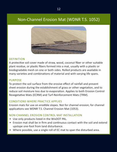
DEFINITIONA protective soil cover made of straw, wood, coconut fiber or other suitable plant residue, or plastic fibers formed into a mat, usually with a plastic or biodegradable mesh on one or both sides. Rolled products are available in many varieties and combinations of material and with varying life spans.
PURPOSETo protect the soil surface from the erosive effect of rainfall and prevent sheet erosion during the establishment of grass or other vegetation, and to reduce soil moisture loss due to evaporation. Applies to both Erosion Control Revegetative Mats (ECRM) and Turf-Reinforcement Mats (TRM).
CONDITIONS WHERE PRACTICE APPLIESErosion mats for use on erodible slopes. Not for channel erosion; for channel applications see WDNR T.S. Channel Erosion Mat (1053).
NON-CHANNEL EROSION CONTROL MAT INSTALLATION• Use only products listed in the WisDOT PAL.• Erosion mat shall be in firm and continuous contact with the soil and extend
upslope one-foot from land disturbance.• Where possible, use a single roll of EC mat to span the disturbed area.
13
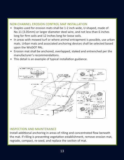
NON-CHANNEL EROSION CONTROL MAT INSTALLATION• Staples used for erosion mats shall be 1-2 inch wide, U-shaped, made of
No.11 (3.05mm) or larger diameter steel wire, and not less than 6 inches long for firm soils and 12 inches long for loose soils.
• In areas with mowed turf or where animal entrapment is possible, use urban mats. Urban mats and associated anchoring devices shall be selected based upon the WisDOT PAL.
• Erosion mat shall be anchored, overlapped, staked and entrenched per the manufacturer’s recommendations.
• This detail is an example of typical installation guidance.
INSPECTION AND MAINTENANCEInstall additional anchoring in areas of rilling and concentrated flow beneath the mat. If rilling is preventing vegetation establishment, remove erosion mat, regrade, compact, re-seed, and replace the section of mat.

14
Channel Erosion Mat (WDNR T.S. 1053)
DEFINITIONA protective soil cover of straw, wood, coconut fiber or other suitable plant residue, or plastic fibers formed into a mat, usually with a plastic or biodegradable mesh on one or both sides. Rolled products are available in many varieties and combination of materials and with varying life spans.
PURPOSETo protect the channel from erosion or act as turf reinforcement during and after the establishment of grass or other vegetation in a channel. Applies to erosion control revegetative mats (ECRM) and turf-reinforcement mats (TRM).
CONDITIONS WHERE PRACTICE APPLIESWhere runoff channelizes in intermittent flow and vegetation is to be established. Some products may have limited applicability in projects adjacent to navigable waters due to potential wildlife entrapment.
• Use channel erosion mat products identified on the WisDOT PAL.• Use WisDOT PAL classes and types to select and specify erosion mat.• Select an erosion mat based on the calculated shear stress, given drainage
area characteristics and channel geometry for the design storm depth.• Select erosion mat that will last until turf grass or other vegetation becomes
densely established.

15
CHANNEL EROSION MAT INSTALLATION• Install and anchor erosion mat in accordance with manufacturer’s
instructions.• At time of installation, retain material labels and manufacturer’s installation
instructions until the site has been stabilized.• Install ECRMs after topsoil is placed and seeding is complete.• Install TRMs in conjunction with placement of topsoil, followed by ECRM
installation.• Install erosion mat so that it bears completely on the soil surface.• Use staples that are at least 6 inches long. • This detail is an example of typical installation guidance.
INSPECTION AND MAINTENANCEInstall additional anchoring in areas of rilling and concentrated flow beneath the mat. If rilling is preventing vegetation establishment, remove erosion mat, regrade, compact, re-seed, and replace the section of mat.

16
Vegetative Buffer (WDNR T.S. 1054)
DEFINITIONAn area of dense vegetation intended to slow runoff and trap sediment. Vegetative buffers are commonly referred to as filter or buffer strips.
PURPOSETo remove sediment in sheet flow by velocity reduction.
CONDITIONS WHERE PRACTICE APPLIESAreas where sediment delivery is in the form of sheet and rill erosion from disturbed areas .
VEGETATIVE BUFFER INSTALLATION• Shall consist of a dense stand of existing grassy vegetation or vegetation
established during the project provided sufficient vegetative cover is established prior to land disturbing activities.
• Must be clearly marked as area of no disturbance, including vehicle traffic.• Vegetative buffers are only effective if sheet flow conditions are present.

17
• This detail is an example of typical installation guidance.
INSPECTION AND MAINTENANCELook for improper distribution of flows, sediment accumulation, and rill erosion. If the vegetative buffer becomes sediment covered, shows rill erosion, or is ineffective, other practices must be implemented.

18
Sediment Bale Barrier (WDNR T.S. 1055)
DEFINITIONA temporary sediment barrier consisting of a row of entrenched and anchored straw bales, hay bales or equivalent material used to intercept sediment-laden sheet flow from small drainage areas of disturbed soil.
PURPOSETo reduce slope length of the disturbed area and to intercept and retain transported sediment from disturbed areas.
CONDITIONS WHERE PRACTICE APPLIESThis standard applies to the following applications where:• Erosion occurs in the form of sheet and rill erosion. There is no
concentration of water flowing to the barrier (channel erosion).• Where adjacent areas need protection from sediment-laden runoff.• Effectiveness is required for less than 3 months.• Conditions allow for the bales to be properly entrenched and staked as
outlined in Criteria Section V of WDNR T.S. Sediment Bale Barrier (1055).Under no circumstance shall products be used in the following applications:• Below the ordinary high watermark or placed perpendicular to flow in
streams, swales, ditches or any place where flow is concentrated.• Where the maximum gradient upslope of the fence is >50% (2:1).

19
SEDIMENT BALE BARRIER INSTALLATION• Install materials per manufacturer’s recommendations.• When joints are necessary, overlap and secure to minimize potential for
concentrated flow. Ends should tie into the slope to prevent erosion from concentrated flow around the ends.
• Should be used in conjunction with permanent restoration practices.• When not used in conjunction with other practices, install spacing per:
Slope Spacing< 2 % 100 feet2 - 5 % 75 feet
5 - 10 % 50 feet
• This detail is an example of typical installation guidance.
INSPECTION AND MAINTENANCELook for indicators that water is eroding around the ends, undercutting the barrier, or erosion is occurring downslope. Remove sediment from behind barrier when reaching 1/2 the height. Remove when permanent vegetation is established.

20
Silt Fence (WDNR T.S. 1056)
DEFINITIONSilt fence is a temporary sediment barrier of entrenched permeable geotextile fabric designed to intercept and slow the flow of sediment-laden sheet flow runoff from small areas of disturbed soil to create ponding.
PURPOSEReduce slope length and intercept and retain sediment from disturbed areas.
CONDITIONS WHERE PRACTICE APPLIESThis standard applies to the following applications where:• Erosion occurs in the form of sheet and rill erosion. There is no
concentration of water flowing to the barrier (channel erosion).• Where adjacent areas need protection from sediment-laden runoff.• Where effectiveness is required for one year or less.• Where conditions allow for silt fence to be properly entrenched and staked
as outlined in Criteria Section V of WDNR T.S. Silt Fence (1056).Under no circumstance shall products be used in the following applications:• Below the ordinary high watermark or placed perpendicular to flow in
streams, swales, ditches or any place where flow is concentrated.• Where the maximum gradient upslope of the fence is >50% (2:1).• Lettering on the fence is not permissible on WisDOT projects. • Must have support cord.
WRONG

21
SILT FENCE INSTALLATION• Construct in an arc with the ends pointing upslope to avoid erosion
around ends of the fence. Best installation method is static slicing. Failure to properly anchor silt fence could result in water and sediment release beneath the silt fence. It is critical to backfill and compact the trench.
• Construct from a continuous roll of geotextile to avoid joints. Where joints are necessary, overlap to the next post or wrap adjoining fabrics together around the joint post and tightly fasten.
• When not used in conjunction with other practices and when using for slope interruption, install spacing per:
Slope Fence Spacing< 2 % 100 feet2 - 5 % 75 feet
5 - 10 % 50 feet10 - 33 % 25 feet> 33 % 20 feet
• This detail is an example of typical installation guidance.
INSPECTION AND MAINTENANCELook for indicators that water is eroding around the ends, undercutting the barrier, or erosion downslope. Remove sediment behind silt fence when reaching 1/2 the height. Remove when permanent vegetation is established.
22
Trackout Control Practices (WDNR T.S. 1057)
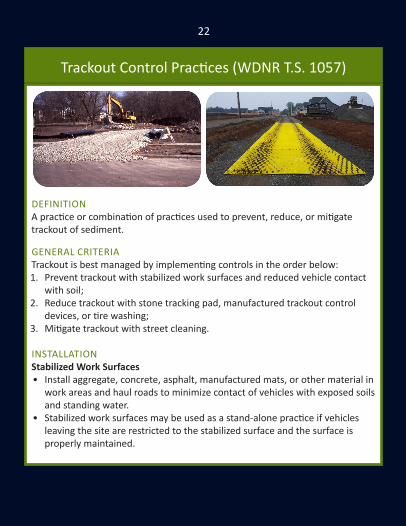
DEFINITIONA practice or combination of practices used to prevent, reduce, or mitigate trackout of sediment.
GENERAL CRITERIATrackout is best managed by implementing controls in the order below:1. Prevent trackout with stabilized work surfaces and reduced vehicle contact
with soil;2 . Reduce trackout with stone tracking pad, manufactured trackout control
devices, or tire washing;3. Mitigate trackout with street cleaning.
INSTALLATION Stabilized Work Surfaces• Install aggregate, concrete, asphalt, manufactured mats, or other material in
work areas and haul roads to minimize contact of vehicles with exposed soils and standing water.
• Stabilized work surfaces may be used as a stand-alone practice if vehicles leaving the site are restricted to the stabilized surface and the surface is properly maintained.

23
Stone Tracking Pads• Install the stone tracking pad to ensure vehicles that drive over exposed soil
exit along the full length of the pad. • Use hard, durable, angular stone or recycled concrete meeting the gradation
in Table 1. Driving surface shall be at least 12 feet wide, 1 foot thick and 50 feet long.
• Where warranted due to soil type or high groundwater, underlay the stone tracking pad with geotextile fabric to minimize migration of underlying soil into the stone. Select fabric type based on soil conditions and vehicle loading.
• Rocks lodged between the tires of dual wheel vehicles shall be removed prior to leaving the construction site.
Manufactured Trackout Control Devices• Install the manufactured trackout control device on a surface capable of
supporting anticipated loads per manufacturer recommendations. • Provide a minimum device length of 32 feet for stand-alone installations.• Add length if needed to reduce trackout in adverse conditions.Tire Washing • Shall be located on site in an area that is stabilized and drains into suitable
sediment trapping or settling device; • Monitor tire washing station for sediment accumulation, clogged hoses,
appropriate water levels, and effectiveness. • For manufactured tire washing stations, operate per manufacturer’s
recommendations.Street/Pavement Cleaning• Scrape and/or sweep pavements and gutters until a shovel-clean or broom-
clean condition is obtained. Repeat as needed to maintain public safety and reduce sediment delivery to drainage infrastructure or water resources, and at the end of each work day.

24
Mulch (WDNR T.S. 1058)
DEFINITIONMulching is the application of organic material to the soil surface to protect it from raindrop impact and overland flow. Mulch covers the soil and absorbs the erosive impact of rainfall and reduces the flow velocity of runoff.
PURPOSETo reduce soil erosion, aid in seed germination and establish plant cover or conserve soil moisture.
CONDITIONS WHERE PRACTICE APPLIESMay be applied on exposed soils as a temporary control where soil grading or landscaping has taken place or in conjunction with temporary or permanent seeding. Mulching is not appropriate in areas of concentrated flow.
ACCEPTABLE MULCH TYPES• Straw or hay in air-dry condition, wood excelsior fiber or wood chips, or
other suitable material of a similar nature that the engineer approves. Use of marsh hay will not be accepted. All mulch material shall be free of noxious weeds and objectionable foreign matter.
• Wood chips or wood bark should be used for temporary stabilization only and should not be used in conjunction with seeding.

25
MULCH INSTALLATIONPrepare area to remove gullies/rills. If seeding, apply prior to mulch. Wood Chips or Bark Mulch• Apply at uniform rate of 9 tons/acre. Mulch should cover a minimum of 80%
of the soil surface with an applied thickness of 0.5 - 1.5 inches.Straw Mulch• Apply at a uniform rate of 2 tons/acre. Mulch should cover a minimum of
70% of the soil surface with an applied thickness of 0.5 - 1.5 inches. • If straw mulch is used without seeding, apply at a uniform rate of 3 tons/
acre. Mulch should cover a minimum of 80% of the soil surface with an applied thickness of 1.5 - 3.0 inches.
• Anchor by crimping or with a tackifier.Straw Mulch Crimping• Just after spreading, anchor mulch using a crimper or equivalent device
consisting of a series of dull flat discs with notched edges spaced approximately 8 inches apart to impress mulch in the soil to a depth of 1 - 3 inches.
Straw Mulch Tackifiers• Select from the approved list in the WisDOT PAL. Apply at a uniform rate. • Spray tackifier at the same time as the mulch application or just after. Do not
spray during conditions preventing proper placement of adhesive.• Apply at manufacturer’s recommended rate or at the rate per acre specified
below, whichever is greater: » Latex base: mix 15 gallons adhesive and a minimum of 250 pounds
recycled newsprint (pulp) as tracer with 375 gallons water; » Guar gum: mix 50 pounds dry adhesive and a minimum of 250 pounds
recycled newsprint (pulp) as tracer with 1,300 gallons water; » Other tackifiers: mix 100 pounds dry adhesive and a minimum of 250
pounds recycled newsprint (pulp) as tracer with 1,300 gallons water.
INSPECTION AND MAINTENANCEReapply as needed.
26
Seeding (WDNR T.S. 1059)
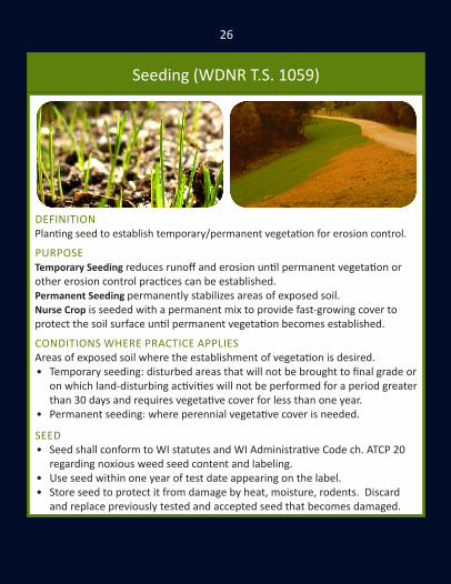
DEFINITIONPlanting seed to establish temporary/permanent vegetation for erosion control.
PURPOSETemporary Seeding reduces runoff and erosion until permanent vegetation or other erosion control practices can be established. Permanent Seeding permanently stabilizes areas of exposed soil.Nurse Crop is seeded with a permanent mix to provide fast-growing cover to protect the soil surface until permanent vegetation becomes established.
CONDITIONS WHERE PRACTICE APPLIESAreas of exposed soil where the establishment of vegetation is desired. • Temporary seeding: disturbed areas that will not be brought to final grade or
on which land-disturbing activities will not be performed for a period greater than 30 days and requires vegetative cover for less than one year.
• Permanent seeding: where perennial vegetative cover is needed.
SEED• Seed shall conform to WI statutes and WI Administrative Code ch. ATCP 20
regarding noxious weed seed content and labeling.• Use seed within one year of test date appearing on the label.• Store seed to protect it from damage by heat, moisture, rodents. Discard
and replace previously tested and accepted seed that becomes damaged.

27
SEEDING INSTALLATIONSeedbed Preparation• Permanent seeding needs a seedbed of at least 4 inches of loose topsoil.• Necessity of fertilizer application should be based on soil testing results.
Prior to seeding, work the area being seeded with appropriate equipment to prepare a tilled fine, but firm, seedbed. Remove rocks, twigs, foreign materials, and dirt clods >2 inches diameter that cannot be broken down.
Sowing• Apply uniformly over the seedbed at the correct seeding rate. Appropriate
seed mixes should be lightly incorporated into the seedbed.DOT Seed Mixture Sowing Rate [pounds/1,000 square feet]
10 1.520 330 240 260 equivalent seeding rate of 1.5
70 and 70A 0.475 0.780 0.8
Temporary Seeding 3Nurse Crop Seeding 0.8
• Seed when soil temperatures remain consistently above 53° F. Avoid seeding during periods where seedlings could be damaged or killed by frost (usually late September to early November).
• Dormant seed after November 1. Do not sow seeds over snow cover.Seed Protection• Protect seed using mulch (WDNR T.S. 1058) or erosion mat (WDNR T.S.
1052). Limit vehicle traffic in areas that have been permanently seeded.
INSPECTION AND MAINTENANCEInspect per permit requirements. Verify seed germination and vegetation establishment. Maintenance includes reapplying mulch and matting, irrigating, regrading, and reseeding.

28
Storm Drain Inlet Protection (WDNR T.S. 1060)
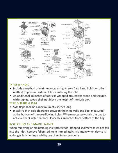
DEFINITIONA temporary device installed around a storm drain inlet, drop inlet or curb inlet.
PURPOSETo minimize sediment from entering storm drainage systems where the contributing drainage area is temporarily disturbed.
STORM DRAIN INLET PROTECTION GENERAL CRITERIA• Inlet protection devices are for drainage areas of one acre or less. • Runoff from areas >1 acre should be routed through a properly designed
sediment trapping or settling practice upstream of the inlet.• Inlet protection devices shall not interfere with the flow of traffic, create a
safety hazard, or cause property damage.• All devices shall have provisions such as overflow holes or “emergency
spillways” to safely pass water if the device becomes clogged.• No gaps shall be left in the material that would allow the flow of water to
bypass the inlet protection device, except for overflow holes.• All fabrics used as part of an inlet protection device must be selected from
the list of Geotextile Fabric, Type FF in the WisDOT PAL. For Types D-M and D-HR inlet devices select Type F, R, DF or HR fabric inserts based on soil type.
29
TYPES B AND C• Include a method of maintenance, using a sewn flap, hand holds, or other
method to prevent sediment from entering the inlet.• An additional 18 inches of fabric is wrapped around the wood and secured
with staples. Wood shall not block the height of the curb box.TYPE D, D-HR, & D-M• Side flaps shall be a maximum of 2 inches long. • Install >3 inch side clearance between the inlet walls and bag, measured
at the bottom of the overflowing holes. Where necessary cinch the bag to achieve the 3 inch clearance. Place ties <4 inches from bottom of the bag.
INSPECTION AND MAINTENANCEWhen removing or maintaining inlet protection, trapped sediment must not fall into the inlet. Remove fallen sediment immediately. Maintain when device is no longer functioning and dispose of sediment properly.
INLET PROTECTION TYPE D-HR
INLET PROTECTION TYPE D-M

30
Dewatering (WDNR T.S. 1061)
DEFINITIONA practice or combination of practices that are used to prevent or reduce the discharge of sediment-laden water from dewatering operations.
PURPOSELand-disturbing construction activity can create conditions where runoff and/or groundwater accumulates in ponds, pits, trenches or other excavations and needs to be removed by pumping or other means of dewatering. The purpose of this standard is to identify common methods which may be used to prevent or reduce the discharge of sediment-laden water from dewatering operations.
CONDITIONS WHERE PRACTICE APPLIESThis standard applies where sediment-laden water needs to be removed by pumping or other means for construction operations or maintenance activities.
Dewatering practices shall meet criteria in the WDNR T.S. Dewatering (1061) Dewatering Practice Selection Matrix.
This practice does not apply to water being discharged directly to groundwater or karst features (see NR140) or well dewatering systems (see NR 812).

31
CONSIDERATIONS• Municipal storm drainage system may need cleaning prior to/after
discharging to prevent scouring solids from the drainage system.• Do not use geotextile bags when discharging to Exceptional Resource
Waters, Outstanding Resource Waters, waterbodies supporting cold water communities, trout streams, or susceptible wetlands.
• Pressurized filtration is most efficient for removing fine sediments.• Portable sediment tanks may be appropriate when other sediment trapping
practices cannot be installed.• Filtration is not an efficient treatment of water with heavy sediment loads.
Use a settling tank or sand filter as pretreatment when possible.• Practices may need to be combined to achieve intended results.
DEWATERING INSTALLATION• Select practices based on soil texture at the dewatering site with
consideration of pumping or flow rates, volumes and device effectiveness. • WDNR T.S. Dewatering (1061) Dewatering Practice Selection Matrix
illustrates acceptable dewatering options and their effective ranges. • Practices selected that are not on the matrix must provide an equivalent
level of control, with justification provided to the reviewing authority.
INSPECTION AND MAINTENANCE• If the dewatering effluent is discolored, has an odor, an oily sheen, or other
toxins are present, notify the DNR immediately: » 24 Hours Spills Reporting Hotline 1-800-943-0003
• Remove sediment from devices. Properly dispose of all sediment collected. • Document test results on a daily log and keep on site:
» Discharge duration and specified pumping rate; » Observed water table at time of dewatering; » If used, type and amount of chemical used for pH adjustment; » If used, type and amount of polymer used for treatment; » Maintenance activities.

32So
il and
Parti
cle Si
ze Cl
assifi
catio
nFin
e to V
ery F
ineCla
y Loa
ms,
Silty
Cla
ys, a
nd Cl
ay
Clay G
eote
xtile
Bag
s
Grav
ity B
ased
Settl
ing
Pass
ive Fi
ltrat
ion
Med
ium to
Fine
Loam
s, Sil
t Loa
ms,
and S
ilts
Coar
se to
Med
iumSa
nd, L
oam
y San
ds,
and S
andy
Loam
s
DEW
ATER
ING
PRA
CTIC
E SE
LECT
ION
MAT
RIX
Type
of D
evic
e
Type
I
Type
II
Sedim
ent T
ank (
Porta
ble)
Sedim
ent T
rap (
Tem
pora
ry)
Sedim
ent B
asin
(Tem
pora
ry)
Wet
Det
entio
n Bas
in (P
erm
anen
t)
Filte
r Tan
k (Po
rtable
)
Filte
r Bas
in
Vege
tativ
e Filt
er
Dewatering Practice Selection Matrix
Effec
tive r
ange
of de
vice:
Devic
e app
licab
le, m
ay no
t be c
ost e
ffect
ive:
Effec
tive r
ange
with
addi
tion o
f pol
ymer
:
(1) T
he eff
ectiv
enes
s of m
any p
racti
ces c
an be
en
hanc
ed th
roug
h the
use o
f poly
mer
mixt
ure.
(2) S
oil cl
assifi
catio
n sha
ll be d
one i
n acco
rdan
ce
to an
acce
pted
met
hod (
i.e. U
SDA,
AASH
TO)

33
Effec
tive r
ange
of de
vice f
or Sa
ndy o
r Clay
ey So
il:De
vice a
pplic
able,
may
not b
e cos
t effe
ctive
:No
t app
licab
le. U
se in
conj
uncti
on w
ith ot
her B
MP’s
:
Soil a
nd Pa
rticle
Size
Clas
sifica
tion
Fine t
o Ver
y Fine
Clay L
oam
s, Sil
ty
Clays
, and
Clay
Pres
suriz
ed Fi
ltrat
ion
Othe
r Pra
ctice
s
Disc
uss w
ith re
gulat
ory a
utho
rity.
Med
ium to
Fine
Loam
s, Sil
t Loa
ms,
and S
ilts
Coar
se to
Med
iumSa
nd, L
oam
y San
ds,
and S
andy
Loam
s
DEW
ATER
ING
PRA
CTIC
E SE
LECT
ION
MAT
RIX
Type
of D
evic
e
Porta
ble Sa
nd Fi
lter
Wou
nd Ca
rtridg
e Unit
s
Mem
bran
es an
d Micr
o-fil
tratio
n
Sanit
ary S
ewer
Disc
harg
e
Pum
p Tru
ck
Alte
rnat
ive M
etho
d
Effec
tive r
ange
of de
vice:
Devic
e app
licab
le, m
ay no
t be c
ost e
ffect
ive:
Effec
tive r
ange
with
addi
tion o
f pol
ymer
:
(1) T
he eff
ectiv
enes
s of m
any p
racti
ces c
an be
en
hanc
ed th
roug
h the
use o
f poly
mer
mixt
ure.
(2) S
oil cl
assifi
catio
n sha
ll be d
one i
n acco
rdan
ce
to an
acce
pted
met
hod (
i.e. U
SDA,
AASH
TO)

34
Ditch Check (WDNR T.S. 1062)
DEFINITIONA temporary dam constructed across a swale, drainage ditch, channel or other area of concentrated flow to reduce the velocity of water. Ditch checks can be constructed out of stone, a double row of straw bales or from manufactured products found on the WisDOT PAL.
PURPOSETo reduce flow velocity and to pond water, thereby reducing active channel erosion and promoting settling of suspended solids behind the ditch check.
GENERAL CRITERIA• Ditch checks shall have a minimum height of 10 inches after installation.• Ditch checks shall not cause ponding that adversely impact or damage
adjacent areas .• Design and install ditch checks to be capable of withstanding anticipated
flow, volume and velocity. • Do not use silt fencing or single rows of straw bales as ditch checks.• Under no circumstance shall ditch checks be placed in intermittent or
perennial stream without permission from WDNR. This practice may not be substituted for sediment control measures such as sediment basins.
• Do not use steel posts or rods to stake ditch checks to avoid safety hazards.
WRONG

35
DESIGN CRITERIAUse the following equation to calculate ditch check spacing in channels:
L = H / SWhere: L = distance between ditch checks, in feet H = height of the ditch check measured from the ditch check overflow invert to the channel bottom on the downslope side of the ditch check, in feet. S = longitudinal slope of the channel in decimal form (e.g. 2% = 0.02)
MANUFACTURED DITCH CHECKS• Use products identified on the WisDOT PAL• Shall be installed in accordance with manufacturer’s recommendations• Entrench manufactured products at least 2 inches or install over erosion
mattingSTONE DITCH CHECKSShall have a minimum top width of 2-ft with a maximum slope of 2:1 on the upslope and downslope sides. Stone shall meet any of the following criteria:1. Well-graded angular stone with a D50
of 3 inches or greater with no more than 5% passing the #4 sieve.
2 . 1-foot layer of 1-inch (#2) washed stone over 3 to 6-inch clear stone.3. Angular stone meeting the gradation for WisDOT Specification 312 select
crush or local equivalent.Stone ditch checks may be constructed using bags or socks filled with stone.
INSPECTION AND MAINTENANCELook for indicators that water is eroding around the ends, undercutting, or erosion is occurring downslope. Remove sediment from behind ditch check when reaching 1/2 the height. Remove when channel permanent vegetation is established, unless part of a permanent plan.

36
Sediment Trap (WDNR T.S. 1063)
DEFINITIONA temporary sediment control device formed by excavation and/or embankment to intercept sediment-laden runoff and to retain the sediment.
PURPOSETo detain sediment-laden runoff from disturbed areas for sufficient time to allow the majority of the sediment to settle out.
CONDITIONS WHERE PRACTICE APPLIES• Areas of concentrated flow or points of discharge during construction
activities. Construct sediment traps at locations accessible for clean out.• Sediment traps are designed to be in place until the contributory drainage
area has been stabilized.• The contributory drainage area shall be a maximum of five acres. For
concentrated flow areas smaller than one acre, ditch checks may be installed; refer to WDNR T.S. Ditch Check (1062).
• For larger drainage areas and/or for sediment basins requiring an engineered outlet structure refer to WDNR T.S. Sediment Basin (1064) or Wet Detention Basin (1001).

37
SEDIMENT TRAP CRITERIATiming• Constructed prior to disturbance of up-slope areas and placed so they
function during all phases of construction and in locations where runoff from disturbed areas can be diverted into the traps.
• Remove and stabilize the sediment trap after the disturbed area draining to sediment trap is stabilized.
Sizing Criteria• Properly sized sediment traps are relatively effective at trapping medium
and coarse-grained particles. • To effectively trap fine-grained particles, the sediment trap must employ a
large surface area or polymers. • See WDNR T.S. Sediment Trap (1063) for specific design criteria. Based on:
» Surface area; » Depth; » Shape; » Side slopes.
Embankments• Not to exceed five feet in height measured from the downstream toe of the
embankment to the top of the embankment. Construct with a minimum top width of four feet, and side slopes of 2:1 or flatter.
• Earthen embankments shall be compacted.• Where sediment traps are employed as a perimeter control, the
embankments shall have stabilization practices in place prior to receiving runoff.
Outlet• Need both a principal outlet and emergency spillway and shall meet WDNR
T.S. Sediment Trap (1063) design criteria.
INSPECTION AND MAINTENANCERemove and properly dispose of sediment deposits when it accumulates to a depth of one foot. Clean outlet when clogged.

38
Sediment Basin (WDNR T.S. 1064)
DEFINITIONA temporary or permanent device constructed with an engineered outlet, formed by excavation or embankment to intercept sediment-laden runoff and retain sediment.
PURPOSEDetain sediment-laden runoff from disturbed areas for sufficient time to allow the majority of the sediment to settle out.
CONDITIONS WHERE PRACTICE APPLIES• Utilize in areas of concentrated flow or points of discharge during
construction activities. Construct at locations accessible for clean out. • Site conditions must allow for runoff to be directed into the basin.• Sediment basins are designed to be in place until the contributory drainage
area has been stabilized. Temporary sediment basins serve drainage areas <100 acres (other practices are often more economical).
• For drainage areas <5 acres, sediment traps or ditch checks may be applicable; for design criteria refer to WDNR T.S. Sediment Trap (1063) or Ditch Check (1062). Design to WDNR T.S. Wet Detention Basin (1001) when a permanent stormwater basin is required.
• Minimum standards for design, installation and performance requirements are deemed 80% effective by design in trapping sediment.

39
SEDIMENT BASIN CRITERIATiming• Construct prior to disturbance and place to function during all phases of
construction, and in locations where runoff can be diverted into the basin.Sizing Criteria• Specific trapping efficiency varies based on the surface area and the particle
size distribution of the sediment entering the device. • Permanent sediment basins must be designed by an engineer.• See WDNR T.S. Sediment Basin (1064) for specific design criteria. Based on:
» Treatment surface area and depth below treatment surface area; » Active storage volume and shape.
Embankments• Design earthen embankments to address potential risk and structural
integrity issues such as seepage and saturation, and meet WDNR T.S. Sediment Basin (1064) design criteria.
Outlet• Need both a principal outlet and an overflow spillway meeting WDNR T.S.
Sediment Basin (1064) design criteria.Inlet Protection • Designed to prevent scour and reduce velocities during peak flows. • Possible design options include flow diffusion, plunge pools, directional
berms, baffles, or other energy dissipation structures.Location• Located to provide access for cleanout and disposal of trapped sediment.Removal• After the contributing drainage area has been stabilized, if temporary. • Complete final grading and restoration according to the site plans. If
standing water needs to be removed see WDNR T.S. Dewatering (1061).
INSPECTION AND MAINTENANCERemove and properly dispose of sediment to maintain three foot depth of the treatment surface area. Clean outlet when clogged.

40
Construction Site Diversion (WDNR T.S. 1066)
DEFINITIONA temporary berm or channel constructed across a slope to collect and divert runoff.
PURPOSETo intercept, divert, and safely convey runoff at construction sites in order to divert clean water away from disturbed areas, or redirect sediment laden waters to an appropriate sediment control facility.
CONDITIONS WHERE PRACTICE APPLIES• Where temporary surface water runoff control or management is needed. • Locations and conditions include:
» Above disturbed areas, to limit runoff onto the site; » Across slopes to reduce slope length; » Below slopes to divert excess runoff to stabilized outlets; » To divert sediment-laden water to sediment control facilities; » At or near the perimeter of the construction area to keep sediment
from leaving the site.• Does not pertain to permanent diversions. Refer to appropriate design
criteria and local regulations when designing permanent diversions.
41
CONSTRUCTION SITE DIVERSION INSTALLATION• Shall have stable side slopes and shall not be overtopped during a 2-year
frequency, 24-hour duration storm. • The minimum berm cross section shall be as follows:
» Side slopes of 2:1 (horizontal:vertical) or flatter; » Top width of two feet; » Berm height of 1.5 feet.
• Sediment-laden runoff from disturbed areas shall be diverted into a sediment control practice. For typical sediment control practices see WDNR T.S. Sediment Trap (1063) or Sediment Basin (1065) for design criteria.
• When diverting clean water, the diversion channel and its outfall shall be immediately stabilized for the 2-year frequency, 24-hour duration storm.
• Build and stabilize clean water diversions before initiating down slope land-disturbing activities.
• Diversions shall be protected from damage by construction activities. • At all points where diversion berms or channels will be crossed by
construction equipment, the diversion shall be stabilized or shaped appropriately .
• Temporary culverts of adequate capacity may be used.• For diversions that are to serve longer than 30 days, the side slopes
including the ridge, and down slope side of the diversion shall be stabilized as soon as they are constructed.
• For diversions serving less than 30 days, the down slope side of the diversion shall be stabilized as soon as constructed.
• The diversion channel should be stabilized (i.e. erosion mat) or an additive sediment control practice, such as ditch checks, shall be installed.
INSPECTION AND MAINTENANCERemove sediment from behind diversion berm when reaching 1/2 the height.

42
Grading Practices for Erosion Ctrl. (WDNR T.S. 1067)
DEFINITIONTemporary grading practices used to minimize construction site erosion. These practices include, but are not limited to surface roughening (directional tracking and tillage) and temporary ditch sumps.
PURPOSETo minimize erosion and sediment transport during grading operations on construction sites.
CONDITIONS WHERE PRACTICE APPLIESWhere land disturbing activities occur on construction sites, to be used in conjunction with other erosion control practices.

43
TEMPORARY GRADING PRACTICES INSTALLATION• These interim practices may be employed in addition to the approved
grading plan to reduce erosion and sediment transport.Surface Roughening• Abrading the soil surface with horizontal ridges and depressions across the
slope to reduce runoff velocities. » Directional tracking: the process of creating ridges with tracked
vehicles by driving up and down unvegetated slopes, used for short durations on sites actively being graded. Use in conjunction with other practices, and place at the end of each workday;
» Tillage: utilizing conventional tillage equipment to create a series of ridges and furrows on the contour no more than 15 inches apart.
Temporary Ditch Sump » Temporary ditch sumps are ½ to 5 cubic yard excavations made in a
drainageway during earthmoving operations. Their purpose is to slow and pond runoff during the time that drainageways are being graded;
» Place sumps prior to anticipated rain events; » Construction involves excavating sumps in the rough ditch grade, and
using the excavated material to form a dike on the downstream side of the sump;
» Temporary ditch sumps are not effective perimeter controls. Utilize other sediment control practices prior to channels discharging into public waterways.
INSPECTION AND MAINTENANCEInspect and repair/reinstall after every runoff event.

44
Dust Control (WDNR T.S. 1068)
DEFINITIONDust control includes practices used to reduce or prevent the surface and air transport of dust during construction. Includes minimization of soil disturbance, applying mulch and establishing vegetation, water spraying, surface roughening, applying polymers, spray-on tackifiers, chlorides, and barriers.
PURPOSE• Reduce wind erosion and dust.• Minimize deposition of dust and wind transported soils into water bodies
through runoff or wind action.• Reduce respiratory problems.• Minimize low visibility conditions caused by airborne dust.
CONDITIONS WHERE PRACTICE APPLIESAt any construction site, but is particularly important for sites with dry exposed soils which may be exposed to wind or vehicular traffic.
DUST CONTROL INSTALLATION• Implementation limits the area exposed for dust generation.• Asphalt and petroleum based products cannot be used.
WRONG
45
Mulch and Vegetation• Mulch or seed and mulch may be applied to protect exposed soil from both
wind and water erosion. Refer to WDNR T.S. Mulching (1058) and Seeding (1059) for criteria.
Water• Water until the surface is wet and repeat as needed, applied at rates so
that runoff does not occur. Treated soil surfaces that receive vehicle traffic require a stone tracking pad or tire washing at all point of egress. Refer to WDNR T.S. Trackout Control Practices (1057) for criteria.
Tillage• Performed with chisel type plows on exposed soils, beginning on the
windward side of the site. Only applicable to flat areas.Additives• Can be effective for areas that do not receive vehicle traffic. Dry applied
additives must be initially watered for activation to be effective for dust control. Refer to WDNR T.S. Land Applied Additives for Erosion Control (1050) for criteria.
Tackifiers and Soil Stabilizers Type A• Products must be selected from and installed at rates conforming to the
WisDOT PAL. Example products include Latex-based and Guar Gum.Chlorides• Apply according to the Wis DOT Standard Specifications for Highway and
Bridge Construction.Barriers • Place barriers at right angles to prevailing wind currents at intervals of about
15 times the barrier height. Solid board fences, snow fences, burlap fences, crate walls, bales of hay and similar material can be used to control air currents and blown soil.
INSPECTION AND MAINTENANCEInspect daily at a minimum.

46
Turbidity Barriers (WDNR T.S. 1069)
DEFINITIONA temporary fabric barrier with low permeability, installed parallel to the flow in or near the bed of a waterway or waterbody to minimize sediment transport.
PURPOSETo provide sediment containment while construction activities are occurring in or directly adjacent to a waterway or waterbody.
CONDITIONS WHERE PRACTICE APPLIESWhere construction activities intrude or are directly adjacent to a waterway or waterbody. This includes but is not limited to bridge construction, rip rap placement, utility work, streambank restoration, boat launches and dredging. Use in conditions with fine soils and flow velocities not exceeding 5 feet per second, unless additional reinforcement is installed.
MATERIAL NOTES• Reusable components of the turbidity barrier shall be clean and free of
potential exotic species. Fabric cannot be reused.• See WDNR T.S. Turbidity Barrier (1069) for detailed material specifications,
per Wis DOT Spec 628.2.10.

47
TURBIDITY BARRIERS INSTALLATION• Refer to WDNR T.S. Turbidity Barriers (1069) for specific criteria.• Install before construction activities are initiated in, or adjacent to the
waterway or waterbody, as close to the construction as practical. • The ends of the barrier shall be securely anchored and keyed into the
shoreline to fully enclose the area where sediment may enter the water.• Follow guidelines outlined in WDNR T.S. Turbidity Barriers (1069) regarding
posts and spacing, flotation devices, height, anchorage, and danger buoys.• Turbidity barriers shall be installed parallel to the direction of flow and shall
not be installed across channels. • Keep in place and maintain until the construction activity is completed and
the disturbed area stabilized.• This detail is an example of typical installation guidance.
INSPECTION AND MAINTENANCEInspect daily and repair if necessary. Do not remove until the water behind the barrier has equal or greater clarity than the waterbody (minimum of 24 hours). When removing the silt curtain, minimize the release or re-suspension of accumulated sediment.
48
Silt Curtain (WDNR T.S. 1070)
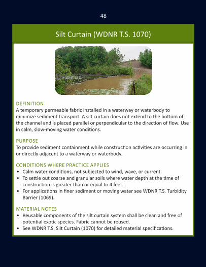
DEFINITIONA temporary permeable fabric installed in a waterway or waterbody to minimize sediment transport. A silt curtain does not extend to the bottom of the channel and is placed parallel or perpendicular to the direction of flow. Use in calm, slow-moving water conditions.
PURPOSETo provide sediment containment while construction activities are occurring in or directly adjacent to a waterway or waterbody.
CONDITIONS WHERE PRACTICE APPLIES• Calm water conditions, not subjected to wind, wave, or current. • To settle out coarse and granular soils where water depth at the time of
construction is greater than or equal to 4 feet.• For applications in finer sediment or moving water see WDNR T.S. Turbidity
Barrier (1069).
MATERIAL NOTES• Reusable components of the silt curtain system shall be clean and free of
potential exotic species. Fabric cannot be reused.• See WDNR T.S. Silt Curtain (1070) for detailed material specifications.

49
SILT CURTAIN INSTALLATIONInstallation• Refer to WDNR T.S. Silt Curtain (1070) for specific criteria.• Install in or adjacent to the waterway or waterbody before construction
activities begin. Install as close to the construction as practical. • Maintain a 2-foot gap between the weighted lower end of the curtain and
the bottom of the waterway or waterbody.• Follow guidelines outlined in WDNR T.S. Silt Curtain (1070) regarding
anchorage and danger buoys.• Must remain in place and be maintained until the construction activity is
completed and the disturbed area is stabilized.• This detail is an example of typical installation guidance.
INSPECTION AND MAINTENANCEInspect daily and repair if necessary. Do not remove until the water behind the curtain has equal or greater clarity than waterbody (minimum 24 hours). When removing the silt curtain, minimize the release or re-suspension of accumulated sediment.

50
Manufactured Slope & Perimeter (WDNR TS. 1071)
DEFINITIONManufactured perimeter control and slope interruption products are designed to detain or slow the flow of sediment-laden sheet flow runoff from small areas of disturbed soil .
PURPOSETo reduce uninterrupted slope length to slow the velocity of runoff so as to retain transported sediment from disturbed areas.
CONDITIONS WHERE PRACTICE APPLIESThis standard applies to the following:• Where only sheet and rill erosion occurs unless the product is approved
for use in concentrated flow areas as a ditch check on Wis DOT PAL and is designed/installed in accordance with WDNR T.S. Ditch Checks (1062).
• Products not approved for concentrated flow that are installed on slopes that terminate in a channel shall be installed no lower than 6 inches above the design flow depth of the channel, limited to 12 months.
• Proper installation (Criteria Section V) and maintenance (Criteria Section VIII) in WDNR T.S. Temporary Slope Break (1071) must be present.
Under no circumstance should products be used in the following:• Below ordinary high watermark or placed perpendicular to flow in streams. • Where the maximum gradient upslope of product is greater than 50% (2:1).

51
TEMPORARY SLOPE BREAKS INSTALLATION• Proprietary products shall be installed per manufacturer’s requirements.• Installed to intercept sheet water flow and direct to an undisturbed area
stabilized with grassy vegetation. Entrench 2 inches with the ends facing upslope. Configure lower end to provide sediment containment.
• The sediment barrier shall be secured with wooden stakes spaced every 4 lineal feet across the length of the barrier. The stakes shall be driven through the center of the barrier into the ground a minimum of 15 inches
• This detail is an example of typical installation guidance.
Slope Slope Break Spacing< 2 % 100 feet2 - 5 % 75 feet
5 - 10 % 50 feet10 - 33 % 25 feet33 - 50 % 20 feet
>50 % Not Permitted•
INSPECTION AND MAINTENANCERemove sediment from behind ditch check when reaching 1/2 the height.
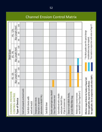
52Di
tch G
rade
9% -
12%
Max
Leng
th [f
eet] 12
0060
030
0
6% -
9%M
ax Le
ngth
[fee
t] 1200
600
300
4% -
6%M
ax Le
ngth
[fee
t] 1200
600
300
CHAN
NEL
ERO
SIO
N
CON
TRO
L M
ATRI
XTy
pe o
f Dev
ice
Seed
with
prop
erly
anch
ored
mulc
h
Sod d
itch c
heck
s with
se
ed an
d mulc
h
Tem
pora
ry di
tch ch
ecks
(h
ay ba
les or
appr
oved
alt
erna
tives
in W
isDOT
PAL)
Sod d
itch l
iner
Doub
le ne
tted l
ight d
uty (
WisD
OT
Class
I Typ
e B) e
rosio
n mat
Sod r
einfo
rced w
ith a
doub
le ne
tted j
ute (
WisD
OT Cl
ass
II Typ
e A) e
rosio
n mat
Ston
e or r
ock d
itch c
heck
s, or
rock
-fille
d filte
r bag
Med
ium du
ty co
conu
t ero
sion
mat
(WisD
OT Cl
ass I
I Typ
e B or
C)
Channel Erosion Control Matrix
Effec
tive r
ange
of de
vice f
or Sa
ndy o
r Clay
ey So
il:De
vice a
pplic
able,
may
not b
e cos
t effe
ctive
:No
t app
licab
le. U
se in
conj
unct
ion w
ith ot
her B
MP’s
:
* For
ditch
grad
es ov
er 9%
spec
ial de
sign
cons
idera
tions
may
be re
quire
d.*U
se m
atrix
in co
njun
ction
with
note
s on P
age 5
7.

53
Effec
tive r
ange
of de
vice f
or Sa
ndy o
r Clay
ey So
il:De
vice a
pplic
able,
may
not b
e cos
t effe
ctive
:No
t app
licab
le. U
se in
conj
uncti
on w
ith ot
her B
MP’s
:
Ditch
Gra
de2%
- 4%
Max
Leng
th [f
eet] 12
0060
030
0
<2%
Max
Leng
th [f
eet] 12
0060
030
0
Perm
issibl
e Sh
ear [
lbs/
squa
re fo
ot]
0.6 N/A
N/A
1.0 1.5 1.5 N/A
2.0
CHAN
NEL
ERO
SIO
N
CON
TRO
L M
ATRI
XTy
pe o
f Dev
ice
Seed
with
prop
erly
anch
ored
mulc
h
Sod d
itch
chec
ks w
ith se
ed an
d mulc
h
Tem
pora
ry di
tch ch
ecks
(hay
bales
or
appr
oved
alte
rnat
ives i
n WisD
OT PA
L)
Sod d
itch l
iner
Doub
le ne
tted l
ight d
uty (
WisD
OT
Class
I Typ
e B) e
rosio
n mat
Sod r
einfo
rced w
ith a
doub
le ne
tted j
ute
(WisD
OT Cl
ass I
I Typ
e A) e
rosio
n mat
Ston
e or r
ock d
itch c
heck
s, or
rock
-fille
d filte
r bag
Med
ium du
ty co
conu
t ero
sion m
at
(WisD
OT Cl
ass I
I Typ
e B or
C)
Effec
tive r
ange
of de
vice f
or Sa
ndy o
r Clay
ey So
il:De
vice a
pplic
able,
may
not b
e cos
t effe
ctive
:No
t app
licab
le. U
se in
conj
unct
ion w
ith ot
her B
MP’s
:
* For
ditch
grad
es ov
er 9%
spec
ial de
sign
cons
idera
tions
may
be re
quire
d.*U
se m
atrix
in co
njun
ction
with
note
s on P
age 5
7.
effec
tive
for c
layey
so
il onl
y

54Di
tch G
rade
9% -
12%
Max
Leng
th [f
eet] 12
0060
030
0
6% -
9%M
ax Le
ngth
[fee
t] 1200
600
300
4% -
6%M
ax Le
ngth
[fee
t] 1200
600
300
CHAN
NEL
ERO
SIO
N
CON
TRO
L M
ATRI
XTy
pe o
f Dev
ice
Heav
y dut
y syn
thet
ic (W
isDOT
Cla
ss III
Type
A) er
osion
mat
or
turf
reinf
orce
men
t mat
(W
isDOT
Clas
s III T
ype B
)
Heav
y dut
y syn
thet
ic tu
rf re
infor
cem
ent (
WisD
OT
Class
III Ty
pe C)
mat
Ripr
ap di
tch ch
ecks
Heav
y dut
y syn
thet
ic tu
rf re
infor
cem
ent (
Class
III Ty
pe D
) mat
Light
ripra
p
Med
ium rip
rap
Heav
y ripr
ap
Grou
ted r
iprap
Channel Erosion Control Matrix
Effec
tive r
ange
of de
vice f
or Sa
ndy o
r Clay
ey So
il:De
vice a
pplic
able,
may
not b
e cos
t effe
ctive
:No
t app
licab
le. U
se in
conj
unct
ion w
ith ot
her B
MP’s
:
* For
ditch
grad
es ov
er 9%
spec
ial de
sign
cons
idera
tions
may
be re
quire
d.*U
se m
atrix
in co
njun
ction
with
note
s on P
age 5
7.
55
Effec
tive r
ange
of de
vice f
or Sa
ndy o
r Clay
ey So
il:De
vice a
pplic
able,
may
not b
e cos
t effe
ctive
:No
t app
licab
le. U
se in
conj
uncti
on w
ith ot
her B
MP’s
:
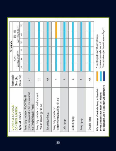
Ditch
Gra
de2%
- 4%
Max
Leng
th [f
eet] 12
0060
030
0
<2%
Max
Leng
th [f
eet] 12
0060
030
0
Perm
issibl
e Sh
ear [
lbs/
squa
re fo
ot]
2.0 3.5 N/A 5 4 5 8 N/A
CHAN
NEL
ERO
SIO
N
CON
TRO
L M
ATRI
XTy
pe o
f Dev
ice
Heav
y dut
y syn
thet
ic (W
isDOT
Clas
s III
Type
A) er
osion
mat
or tu
rf re
infor
cem
ent
mat
(WisD
OT Cl
ass I
II Typ
e B)
Heav
y dut
y syn
thet
ic tu
rf re
infor
cem
ent
(WisD
OT Cl
ass I
II Typ
e C) m
at
Ripr
ap di
tch ch
ecks
Heav
y dut
y syn
thet
ic tu
rf re
infor
cem
ent (
Class
III Ty
pe D
) mat
Light
ripra
p
Med
ium rip
rap
Heav
y ripr
ap
Grou
ted r
iprap
Effec
tive r
ange
of de
vice f
or Sa
ndy o
r Clay
ey So
il:De
vice a
pplic
able,
may
not b
e cos
t effe
ctive
:No
t app
licab
le. U
se in
conj
unct
ion w
ith ot
her B
MP’s
:
* For
ditch
grad
es ov
er 9%
spec
ial de
sign
cons
idera
tions
may
be re
quire
d.*U
se m
atrix
in co
njun
ction
with
note
s on P
age 5
7.

56Di
tch G
rade
9% -
12%
Max
Leng
th [f
eet]
1200
600
300
6% -
9%M
ax Le
ngth
[fee
t]12
0060
030
0
< 6%
Max
Leng
th [f
eet]
1200
600
300
Perm
issibl
e Sh
ear [
lbs/
squa
re fo
ot]
5 10 15 20 30
CHAN
NEL
ERO
SIO
N
CON
TRO
L M
ATRI
XTy
pe o
f Dev
ice
Artic
ulate
d Con
crete
Bl
ock T
ype A
Artic
ulate
d Con
crete
Bl
ock T
ype B
Artic
ulate
d Con
crete
Bl
ock T
ype C
Artic
ulate
d Con
crete
Bl
ock T
ype D
Artic
ulate
d Con
crete
Bl
ock T
ype E
Channel Erosion Control Matrix
Effec
tive r
ange
of de
vice f
or Sa
ndy o
r Clay
ey So
il:De
vice a
pplic
able,
may
not b
e cos
t effe
ctive
:No
t app
licab
le. U
se in
conj
unct
ion w
ith ot
her B
MP’s
:
* For
ditch
grad
es ov
er 9%
spec
ial de
sign
cons
idera
tions
may
be re
quire
d.*U
se m
atrix
in co
njun
ction
with
note
s on P
age 5
7.

57
Effec
tive r
ange
of de
vice f
or Sa
ndy o
r Clay
ey So
il:De
vice a
pplic
able,
may
not b
e cos
t effe
ctive
:No
t app
licab
le. U
se in
conj
uncti
on w
ith ot
her B
MP’s
:
NOTES FOR THE CHANNEL EROSION CONTROL MATRIX1) Ditch flow rates used to develop bar chart are based on a 60 foot right
of way (ROW) from pavement centerline and a 2-year rainfall event for temporary liners or a 25-year rainfall event for permanent (Class III mat or riprap) liners. If the drainage area extends outside the 60 foot ROW or unusual flows are expected, use the shear stress column values to determine the suitablity of a liner. See FDM procedures in Chapter 10 and in Section 13-30-10.
2) Erosion mats shall extend upslope 1 foot minimum vertically from the ditch bottom or 6” higher than the design flow depth. There shall be no joints within 18” of the low point.
3) Cost shall be a consideration in the selection of these devices.4) Add sediment traps at the bottom of channel slopes.5) Refer to FDM Chapter 10 for any channels exceeding the limits shown.6) Approved materials for erosion products are referenced from the Wis DOT
PAL: https://wisconsindot.gov/Pages/doing-bus/eng-consultants/cnslt-rsrces/tools/pal/default .aspx
7) On long or steep channels that require a higher class mat, use the appropriate lower class mat for the first 300-600 feet of the channel.
8) Effective erosion control involves minimizing the amount of time soil is exposed and the selection of a combination of practices, and not reliance on just one practice.
STANDARD DITCH SECTION

58Slo
pe1:1
Slope
Leng
th [f
eet]
60-1
20
Used
in co
njun
ction
with
othe
r BM
Ps eff
ectiv
e up t
o a 2:
1 slop
e. No
t effe
ctive
in
sand
. Whe
n use
d alon
e effe
ctive
up to
a 3:1
slop
e. St
and a
lone u
se
appr
opria
te fo
r ear
then
stoc
k pile
s, te
mpo
rary,
and l
ate s
easo
n app
licat
ions.
30-6
00-
30
2:1Slo
pe Le
ngth
[fee
t]60
-120
30-6
00-
30
2.5:1
Slope
Leng
th [f
eet]
60-1
2030
-60
0-30
SLO
PE E
ROSI
ON
CO
NTR
OL
MAT
RIX
Type
of D
evic
e
Seed
with
prop
erly
anch
ored
mulc
h
Single
nette
d ligh
t dut
y (W
isDOT
Cla
ss I T
ype A
) ero
sion m
at
Light
duty
sing
le ne
tted 1
00%
bio
degr
adea
ble (W
isDOT
Ur
ban T
ype A
) ero
sion m
at
Light
duty
doub
le ne
tted
100%
biod
egra
deab
le (W
isDOT
Ur
ban T
ype B
) ero
sion m
at
Bond
ed M
ulch (
WisD
OT
Type
A So
il Sta
bilize
r)
Polym
er (W
isDOT
Type
B S
oil St
abiliz
er)
Doub
le ne
tted l
ight d
uty (
WisD
OT
Class
I Typ
e B) e
rosio
n mat
Sod
Slope Erosion Control Matrix
Effec
tive r
ange
of de
vice f
or Sa
ndy o
r Clay
ey So
il:De
vice a
pplic
able,
may
not b
e cos
t effe
ctive
:No
t app
licab
le. U
se in
conj
unct
ion w
ith ot
her B
MPs
:
* For
ditch
grad
es ov
er 9%
spec
ial de
sign
cons
idera
tions
may
be re
quire
d.*U
se m
atrix
in co
njun
ction
with
note
s on P
age 6
2.

59
Effec
tive r
ange
of de
vice f
or Sa
ndy o
r Clay
ey So
il:De
vice a
pplic
able,
may
not b
e cos
t effe
ctive
:No
t app
licab
le. U
se in
conj
uncti
on w
ith ot
her B
MP’s
:
Slope
3:1Slo
pe Le
ngth
[fee
t]60
-120
Used
in co
njun
ction
with
othe
r BM
Ps eff
ectiv
e up t
o a 2:
1 slop
e. No
t effe
ctive
in
sand
. Whe
n use
d alon
e effe
ctive
up to
a 3:1
slop
e. St
and a
lone u
se
appr
opria
te fo
r ear
then
stoc
k pile
s, te
mpo
rary,
and l
ate s
easo
n app
licat
ions.
30-6
00-
30
4:1Slo
pe Le
ngth
[fee
t]60
-120
30-6
00-
30
6:1 or
flatte
rSlo
pe Le
ngth
[fee
t]60
-120
30-6
00-
30
SLO
PE E
ROSI
ON
CO
NTR
OL
MAT
RIX
Type
of D
evic
e
Seed
with
prop
erly
anch
ored
mulc
h
Single
nette
d ligh
t dut
y (W
isDOT
Cla
ss I T
ype A
) ero
sion m
at
Light
duty
sing
le ne
tted 1
00%
bio
degr
adea
ble (W
isDOT
Ur
ban T
ype A
) ero
sion m
at
Light
duty
doub
le ne
tted
100%
biod
egra
deab
le (W
isDOT
Ur
ban T
ype B
) ero
sion m
at
Bond
ed M
ulch (
WisD
OT
Type
A So
il Sta
bilize
r)
Polym
er (W
isDOT
Type
B So
il Sta
bilize
r)
Doub
le ne
tted l
ight d
uty (
WisD
OT
Class
I Typ
e B) e
rosio
n mat
Sod
Effec
tive r
ange
of de
vice f
or Sa
ndy o
r Clay
ey So
il:De
vice a
pplic
able,
may
not b
e cos
t effe
ctive
:No
t app
licab
le. U
se in
conj
unct
ion w
ith ot
her B
MPs
:
* For
ditch
grad
es ov
er 9%
spec
ial de
sign
cons
idera
tions
may
be re
quire
d.*U
se m
atrix
in co
njun
ction
with
note
s on P
age 6
2.

60Slo
pe1:1
Slope
Leng
th [f
eet]
60-1
2030
-60
0-30
2:1Slo
pe Le
ngth
[fee
t]60
-120
30-6
00-
30
2.5:1
Slope
Leng
th [f
eet]
60-1
2030
-60
0-30
SLO
PE E
ROSI
ON
CO
NTR
OL
MAT
RIX
Type
of D
evic
e
Med
ium du
ty co
conu
t ero
sion
mat
(WisD
OT Cl
ass I
I Typ
e B or
C)
Sod r
einfo
rced w
ith a
doub
le ne
tted j
ute (
WisD
OT Cl
ass
II Typ
e A) e
rosio
n mat
Heav
y dut
y syn
thet
ic er
osion
co
ntro
l reve
geta
tion m
at
(WisD
OT Cl
ass I
II Ty
pe A)
Ripr
ap
Heav
y dut
y syn
thet
ic tu
rf re
infor
cem
ent (
WisD
OT
Class
III Ty
pe B
or C)
mat
Heav
y dut
y syn
thet
ic tu
rf re
infor
cem
ent (
WisD
OT
Class
III Ty
pe D
) mat
Slope
pavin
g or g
rout
ed rip
rap
Slope Erosion Control Matrix
Effec
tive r
ange
of de
vice f
or Sa
ndy o
r Clay
ey So
il:De
vice a
pplic
able,
may
not b
e cos
t effe
ctive
:No
t app
licab
le. U
se in
conj
unct
ion w
ith ot
her B
MPs
:
* For
ditch
grad
es ov
er 9%
spec
ial de
sign
cons
idera
tions
may
be re
quire
d.*U
se m
atrix
in co
njun
ction
with
note
s on P
age 6
2.

61
Effec
tive r
ange
of de
vice f
or Sa
ndy o
r Clay
ey So
il:De
vice a
pplic
able,
may
not b
e cos
t effe
ctive
:No
t app
licab
le. U
se in
conj
uncti
on w
ith ot
her B
MP’s
:
“ l on
ly* F
or di
tch gr
ades
over
9% sp
ecial
desig
n con
sider
ation
s may
be re
quire
d.**
Soils
that
are n
ot sa
ndy s
hould
be tr
eate
d as c
lay so
ils.
Slope
3:1Slo
pe Le
ngth
[fee
t]60
-120
30-6
00-
30
4:1Slo
pe Le
ngth
[fee
t]60
-120
30-6
00-
30
6:1 or
flatte
rSlo
pe Le
ngth
[fee
t]60
-120
30-6
00-
30
SLO
PE E
ROSI
ON
CO
NTR
OL
MAT
RIX
Type
of D
evic
e
Med
ium du
ty co
conu
t ero
sion m
at
(WisD
OT Cl
ass I
I Typ
e B or
C)
Sod r
einfo
rced w
ith a
doub
le ne
tted j
ute (
WisD
OT Cl
ass I
I Ty
pe A)
eros
ion m
at
Heav
y dut
y syn
thet
ic er
osion
co
ntro
l reve
geta
tion m
at
(WisD
OT Cl
ass I
II Ty
pe A)
Ripr
ap
Heav
y dut
y syn
thet
ic tu
rf re
infor
cem
ent (
WisD
OT Cl
ass
III Ty
pe B
or C)
mat
Heav
y dut
y syn
thet
ic tu
rf re
infor
cem
ent (
WisD
OT
Class
III Ty
pe D
) mat
Slope
pavin
g or g
rout
ed rip
rap
Effec
tive r
ange
of de
vice f
or Sa
ndy o
r Clay
ey So
il:De
vice a
pplic
able,
may
not b
e cos
t effe
ctive
:No
t app
licab
le. U
se in
conj
unct
ion w
ith ot
her B
MPs
:
* For
ditch
grad
es ov
er 9%
spec
ial de
sign
cons
idera
tions
may
be re
quire
d.*U
se m
atrix
in co
njun
ction
with
note
s on P
age 6
2.

62SL
OPE
ERO
SIO
N C
ON
TRO
L M
ATRI
X
Ero
sion
Con
trol
Cons
ider b
ench
es w
hen c
uts e
xcee
d 20’,
benc
h at a
ppro
ximat
ely 15
’ ver
tical
inter
vals
to co
llect
and d
rain
wate
r. Tre
at be
nche
s as c
hann
els (d
itche
s).
Adjus
t elev
ation
s to p
rovid
e dra
inage
. Con
sider
flum
es at
tran
sition
s.Us
ed to
inte
rcept
runo
ff fro
m ab
uttin
g lan
ds. F
lumes
m
ay be
nece
ssary
to di
rect
runo
ff.Us
ed at
toe o
f slop
es to
inte
rcept
and d
etain
small
amou
nts o
f se
dimen
t. Us
e onl
y Wis
DOT a
ppro
ved s
ilt fe
nce a
s list
ed in
the P
AL.
Used
at to
e of s
lopes
to in
terce
pt an
d det
ain sm
all am
ount
s of s
edim
ent.
May
be ne
cessa
ry on
slop
es (s
ee ch
anne
l mat
rix fo
r des
ign gu
idanc
e).
Used
to tr
ap se
dimen
t lad
en ru
noff.
Could
be us
ed
at th
e inl
et or
outle
t end
of sl
ope d
rain.
Benc
hes
Inte
rcept
ing
emba
nkm
ents
Silt f
ence
Tem
pora
ry di
tch ch
ecks
or
eros
ion ba
les
Slope
drain
s/flum
es
Sedim
ent t
raps
Slope Erosion Control Matrix
NO
TES
FOR
THE
SLO
PE E
ROSI
ON
CO
NTR
OL
MAT
RIX
1) C
ost s
hall
be a
con
sider
ation
in th
e se
lecti
on o
f the
se d
evic
es.
2) D
esig
ners
shou
ld re
view
FDM
Cha
pter
10
prio
r to
sele
ction
of e
rosio
n m
ats.
3) In
stal
l int
erce
pting
ditc
hes t
o lim
it slo
pe le
ngth
s to
15’ v
ertic
al in
terv
als (
see
FDM
Cha
pter
10)
.4)
Ref
er to
FDM
Cha
pter
10
for a
ny sl
opes
exc
eedi
ng th
e lim
its sh
own.
5) A
ppro
ved
mat
eria
ls fo
r ero
sion
prod
ucts
are
refe
renc
ed fr
om th
e W
is DO
T PA
L:
https
://w
iscon
sindo
t.gov
/Pag
es/d
oing
-bus
/eng
-con
sulta
nts/
cnslt
-rsr
ces/
tool
s/pa
l/de
faul
t .asp
x6)
On
stee
per s
lope
s tha
t req
uire
a h
ighe
r cla
ss m
at, u
se th
e ap
prop
riate
low
er
clas
s mat
or s
eed
and
mul
ch fo
r the
firs
t 30-
60 fe
et o
f the
slop
e.7)
Unl
ess p
roje
ct c
ondi
tions
requ
ire o
ther
wise
, see
d an
d m
ulch
all
slope
s tha
t are
fla
tter t
han
a 5%
gra
de, r
egar
dles
s of l
engt
h. If
pra
ctica
ble,
ben
ch th
e slo
pes.
8) E
ffecti
ve e
rosio
n co
ntro
l inv
olve
s min
imizi
ng th
e du
ratio
n of
soil
expo
sure
and
th
e se
lecti
on o
f a c
ombi
natio
n of
pra
ctice
s, a
nd n
ot re
lianc
e on
just
one
pra
ctice
.

63
WisDOT Erosion Mat Categories
Class I Short Term Organic
Type AShear 1.0 lbs/square foot
Slopes up to 2.5:1
Type BShear 1.5 lbs/square foot
Slopes up to 2:1Light Duty Channel Liner
Class I, UrbanFor Use in Urban,
Residential Areas, and Environmentally Sensitive
Areas
Urban, Type ASlopes up to 4:1
Biodegradable Netting
Class II Long Term Organic
Type AJute for Sod
Reinforcement
Type BShear 2.0 lbs/square foot
Slopes up to 2:1Medium Duty Channel Liner
Synthetic Netting OK
Type CShear 2.0 lbs/square foot
Slopes up to 2:1Medium Duty
Channel Liner, 100% Organic Fiber Required
Class III Permanent Synthetic
Type AShear 2.0 lbs/square foot
ECRM MatSlopes up to 2:1
Channel Liner
Type BShear 2.0 lbs/square foot
TRM MatSlopes up to 2:1
Channel Liner
Type CShear 3.5 lbs/square foot
TRM MatSlopes up to 2:1
Heavy Duty Channel Liner
Type DShear 5.0 lbs/square foot
TRM MatSlopes up to 1:1
Heavy Duty Channel Liner
Urban, Type BShear 1.0 lbs/square foot
Slopes up to 2.5:1Biodegradable Netting

64
• The environmental monitor will inspect erosion and sediment control practices a minimum of:
» Once a week; » Within 24 hours following a rainfall of 0.5 inches or more.
• Take corrective action as soon as possible with consideration of site conditions, at the most within 24 hours of the inspection.
• Maintain written documentation of the inspection at the construction site describing:
» Date, time, and location of construction site inspection; » Name of individual performing inspection; » Assessment of the condition of erosion and sediment controls; » Description of any corrective erosion and sediment control
implementation or maintenance performed; » Description of the current location and phase of land disturbing
activity.• For a sample construction site inspection report form:
https://dnr.wi.gov/files/PDF/forms/3400/3400-187.pdf
General Inspection and Maintenance Guidance

65

Many thanks to Emmons and Olivier Resources for donating staff time and resources to develop this guide.
(608) 839-4422 | www.eorinc.com
Visit us online to see upcoming training events and professional development opportunities.
www.nasecawi.org