quivira erosion control field guide
DESCRIPTION
GUIDING PRINCIPLES1. Protect and expand moisture storing areas of the landscape.2. Stabilize active erosion and prevent further degradation.3. Restore dispersed flow and increase infiltration at every opportunity.4. Cultivate restorative plant communities to build soil.5. Create site-specific solutions using natural forms and processes.For more information visit www.DrylandSolutions.com and www.QuiviraCoalition.orgTRANSCRIPT

EROSION CONTROL EROSION CONTROL
FIELD GUIDEFIELD GUIDE
1. Protect and expand moisture storing areas of the landscape.
2. Stabilize active erosion and prevent further degradation.
3. Restore dispersed flow and increase infiltration at every opportunity.
4. Cultivate restorative plant communities to build soil.
5. Create site-specific solutions using natural forms and processes.
For more information visit www.DrylandSolutions.com
and www.QuiviraCoalition.org
GUIDING PRINCIPLES By Craig Sponholtz & Avery C. Anderson
© 2010 CS AA

A low grade control structure built with a single layer of rock on the bed of the channel. ORDs stabilize the bed of the channel by slowing the flow of water, increasing roughness, recruiting vegetation, capturing sediment, and gradually raising the bed level over time. ORDs are also passive water harvesting structures. The single layer of rock is an effective rock mulch that increases soil moisture, infiltration, and plant growth. Original concept developed by Bill Zeedyk.
Design & Construction 1. Select area to build the ORD; dig a shallow footer trench and fill with one or two rows of rock, so that no rock protrudes
more than 2 in/5cm above the bed of the channel. This will serve as the splash apron for the ORD. 2. Scatter native grass and wildflower seeds in the area where the ORD is to be built. 3. Start building at the footer and continue upstream, laying down one layer of rock horizontally, as if you were building a rock
wall. 4. Once the ORD is completely filled with sediment, another layer can be added to further raise the bed of the channel and
capture more sediment. The original ORD becomes the splash apron for the new layer.
Orientation of Rocks: Placing rocks vertically
is called book-stacking, this makes a very strong structure, especially when using small rocks. It is also a good way to make a slightly higher structure.
Direction of flow
© 2010 CS AA
ONE ROCK DAM “ORD”
STEP 1: Dig trench and build footer
STEP 3: Start at footer and build upstream
STEP 2: Seed area STEP 4: When ORD fills in, add a new layer
Book-stacked rocks are vertically placed Rocks placed flat
ONE ROCK DAM
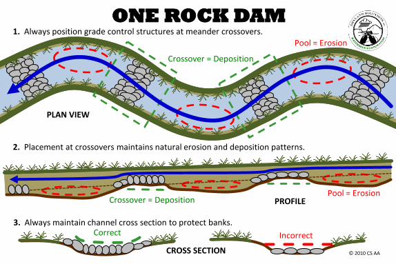
PLAN VIEW
Pool = Erosion
Crossover = Deposition
Pool = Erosion PROFILE Crossover = Deposition
1. Always position grade control structures at meander crossovers.
3. Always maintain channel cross section to protect banks.
2. Placement at crossovers maintains natural erosion and deposition patterns.
Correct Incorrect
CROSS SECTION © 2010 CS AA
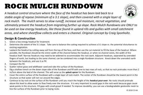
A headcut control structure where the face of the headcut has been laid back to a stable angle of repose (minimum of a 3:1 slope), and then covered with a single layer of rock mulch. The mulch serves to slow runoff, increase soil moisture, recruit vegetation, and ultimately prevent the headcut from migrating further up slope. Rock Mulch Rundowns are ONLY to be used on low energy headcuts, like those found in upland rills and gullies with small catchment areas, and where sheetflow collects and enters a channel. Original concept by Craig Sponholtz.
Design & Construction 1. Select a low energy headcut for treatment. 2. Determine the extent of the 3:1 slope. Take care to balance the cutting required to achieve a 3:1 slope vs. the potential disturbance to
existing vegetation. 3. Layback the headcut by cutting away soil from the top of the face, and then use the cut material to fill the base of the headcut. Where
possible, the Rundown should be the entire width of the channel below the headcut, or when no channel exists, the width of the headcut itself. Narrow headcuts may need to be widened to accommodate the rock work. Adjacent headcuts, separated by uneroded fingers of earth, but leading to the same channel, can be combined into a single Rundown structure. Knock down the uneroded earth between the headcuts, and use it as fill.
4. Compact the fill. 5. Scatter native grass and wildflower seed and rake the surface of the Rundown. 6. Dig a shallow trench on the down slope side of the Rundown and fill with one to two rows of rock, so that no rock protrudes more than 2
in/5cm above the bed of the channel. This will serve as the splash apron for the Rundown. 7. Cover the entire surface of the Rundown with a single layer of rock mulch. The center of the Rundown should be the lowest point in the
structure so that water will not run around the edges. 8. Continue to lay rock on the surface of the Rundown until you reach the height of the headcut pour-over. No rocks should protrude
above this level to allow water to flow freely over the structure. It is very important to avoid gaps in the rock work because gaps cause weak points in the structure. Fill gaps with small gravel if needed. To improve durability, you can use a biodegradable geotextile mesh to line the surface of the Rundown prior to laying rocks.
© 2010 CS AA
ROCK MULCH RUNDOWN
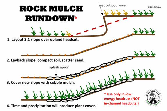
ROCK MULCH
RUNDOWN*
1. Layout 3:1 slope over upland headcut.
2. Layback slope, compact soil, scatter seed.
3. Cover new slope with cobble mulch.
4. Time and precipitation will produce plant cover.
* Use only in low energy headcuts (NOT in-channel headcuts!)
© 2010 CS AA
splash apron
headcut pour-over
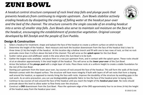
Design & Construction 1. Select a headcut for treatment; shape and layback the face of the headcut to create a uniform surface on which to build. 2. Determine the height of the headcut. Next measure and mark the location downstream from the face of the headcut that is two to
three times (2-3x) the height of the headcut. At this location dig a shallow trench and fill with one to two rows of rock, so that no rock protrudes more than 2 in/5cm above the bed of the channel. This will serve as the splash apron for the Zuni Bowl.
3. Scatter native grass and wildflower seeds in the area where the Zuni Bowl is to be built. 4. Gather the largest rocks available, and place them in a row just upstream from, and in contact with the splash apron. These rocks should
sit at an elevation approximately ½ the total height of the headcut. This will serve as the lower pour-over of the Zuni Bowl. 5. Armor the bottom of the plunge pool with a single layer of rocks. Place these rocks at a uniform height to create a stable foundation for
the rest of the Zuni Bowl. 6. Starting just upstream from the lower pour-over, lay courses of rock around the face of the headcut. This will form the walls of the bowl.
Maintain contact with the shaped surface. The structure will have more integrity if built with layers of off-set rocks that form a sloping wall around the headcut, as opposed to merely lining the face with rocks. Improve the durability of the structure by avoiding gaps in the rock work. As an extra precaution, you can use biodegradable geotextile fabric to line the face of the headcut prior to laying rocks.
7. Continue to lay courses of rock around the face of the headcut until you reach the height of the headcut pour-over. No rocks should protrude above this level to allow water to flow freely over the structure.
8. Construct a ORD downstream from the Zuni Bowl. Place the upstream edge of the ORD approximately four to six times (4-6x) the height of the headcut away from the headcut pour-over.
ZUNI BOWL A headcut control structure composed of rock lined step falls and plunge pools that prevents headcuts from continuing to migrate upstream. Zuni Bowls stabilize actively eroding headcuts by dissipating the energy of falling water at the headcut pour-over and the bed of the channel. The structure converts the single cascade of an eroding headcut into a series of smaller step falls. Zuni Bowls also serve to maintain soil moisture on the face of the headcut, encouraging the establishment of protective vegetation. Original concept developed by Bill Zeedyk and the people of Zuni Pueblo.
© 2010 CS AA

ZUNI BOWL
lower pour-over [½ height of headcut pour-over]
splash apron
headcut pour-over
2-3x height of headcut © 2010 CS AA
one rock dam
4-6x height of headcut
plunge pool
plunge pool

MEDIA LUNA There are two types of Media Luna structures – both used to manage sheet flow and prevent erosion. “Sheet flow collectors” (tips DOWN) prevent erosion (i.e. headcuts) at the head of rills and gullies by creating a stable transition from sheet flow to channel flow at the collection point. “Sheet flow spreaders” (tips UP) are used on relatively flat ground to disperse erosive channelized flow and reestablish sheet flow where it once occurred. Original concept developed by Van Clothier, and expanded upon by Craig Sponholtz.
Design & Construction 1. Identify which type of Media Luna (i.e. “tips UP” or “tips DOWN”) is appropriate for the treatment site. 2. If the treatment site is at the collection point of a network of rills (< 6 in/15cm deep) or small channels (< 1 ft/30cm deep) then use a
sheet flow collector (tips DOWN). First lay out the down-slope edge of the structure by selecting two points on the banks of the main channel immediately down slope from where the rills enter. Using a leveling tool, lay out a level arc from bank to bank so that the tips point down slope, and the arc spans all of the rills that you aim to treat.
3. If the treatment site is located where runoff from rills or a shallow channel can easily be spread across relatively flat ground, then use a sheet flow spreader (tips UP). First lay out the down-slope edge of the structure by creating a level arc across the flat area with the tips on a slightly higher contour. The tips should be far enough up-slope that they prevent water from running around the ends of the structure.
4. For both sheet flow collectors and sheet flow spreaders - lay out the up-slope edge of the structure by tracing a level arc parallel to the down-slope edge to create a band that is at least 3 ft/1m wide. Media Lunas composed of wider bands of cobble mulch offer more protection from erosion, improved infiltration and increased plant recruitment.
5. Start by digging a shallow trench from tip to tip along the down-slope edge. Fill the trench with one to two rows of rock, so that no rock protrudes more than 2 in/5cm above ground level. This will serve as the splash apron for the Media Luna.
6. Scatter native grass and wildflower seeds in the area where the Media Luna is to be built. 7. For both types of Media Lunas, start on the down-slope edge and work up slope covering the ground with a single layer of cobble
mulch to form a band at least 3 ft/1m wide. The tops of the rocks on the up-slope edge need to be level to ensure proper function of the structure.
© 2010 CS AA
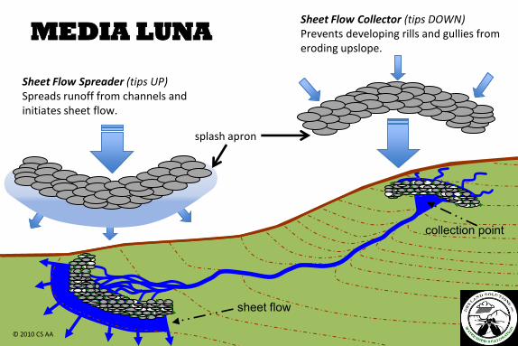
MEDIA LUNA
Sheet Flow Spreader (tips UP) Spreads runoff from channels and initiates sheet flow.
Sheet Flow Collector (tips DOWN) Prevents developing rills and gullies from eroding upslope.
© 2010 CS AA
collection point
sheet flow
splash apron
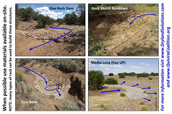
One Rock Dam Rock Mulch Rundown
Media Luna (tips UP)
Zuni Bowl
© 2
010
CS
AA
Wh
en
po
ssib
le u
se m
ate
rial
s av
aila
ble
on
-sit
e.
NO
TE:
man
y ty
pe
s o
f ro
ck c
an b
e u
sed
to
bu
ild t
he
se s
tru
ctu
res.
For
mo
re in
form
ati
on
vis
it w
ww
.Dry
lan
dSo
luti
on
s.co
m
an
d w
ww
.Qu
ivir
aC
oa
litio
n.o
rg