wireless sd shield · included on board is a sd card slot. when using the sd library to access the...
TRANSCRIPT
Search the Arduino Website
Wireless SD Shield
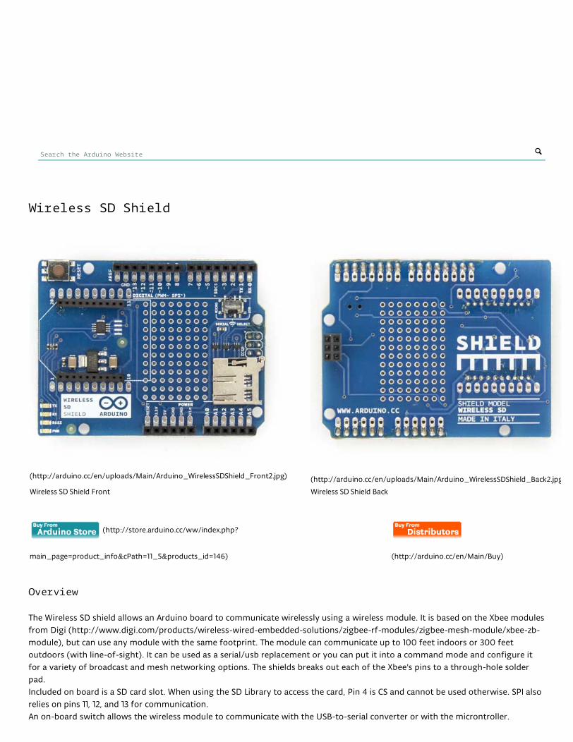
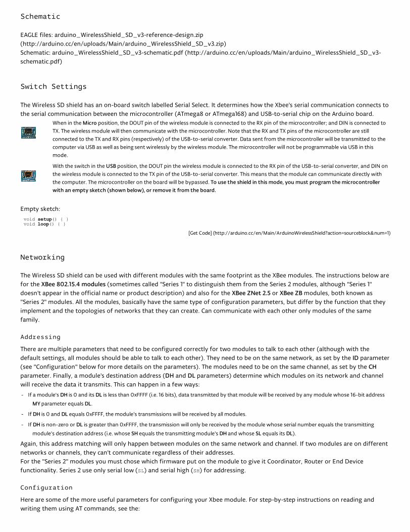
(http://arduino.cc/en/uploads/Main/Arduino_WirelessSDShield_Front2.jpg) (http://arduino.cc/en/uploads/Main/Arduino_WirelessSDShield_Back2.jpg)
Wireless SD Shield Front Wireless SD Shield Back
(http://store.arduino.cc/ww/index.php?
main_page=product_info&cPath=11_5&products_id=146) (http://arduino.cc/en/Main/Buy)
Overview
The Wireless SD shield allows an Arduino board to communicate wirelessly using a wireless module. It is based on the Xbee modules
from Digi (http://www.digi.com/products/wireless-wired-embedded-solutions/zigbee-rf-modules/zigbee-mesh-module/xbee-zb-
module), but can use any module with the same footprint. The module can communicate up to 100 feet indoors or 300 feet
outdoors (with line-of-sight). It can be used as a serial/usb replacement or you can put it into a command mode and configure it
for a variety of broadcast and mesh networking options. The shields breaks out each of the Xbee's pins to a through-hole solder
pad.
Included on board is a SD card slot. When using the SD Library to access the card, Pin 4 is CS and cannot be used otherwise. SPI also
relies on pins 11, 12, and 13 for communication.
An on-board switch allows the wireless module to communicate with the USB-to-serial converter or with the microntroller.
Schematic
EAGLE files: arduino_WirelessShield_SD_v3-reference-design.zip
(http://arduino.cc/en/uploads/Main/arduino_WirelessShield_SD_v3.zip)
Schematic: arduino_WirelessShield_SD_v3-schematic.pdf (http://arduino.cc/en/uploads/Main/arduino_WirelessShield_SD_v3-
schematic.pdf)
Switch Settings
The Wireless SD shield has an on-board switch labelled Serial Select. It determines how the Xbee's serial communication connects to
the serial communication between the microcontroller (ATmega8 or ATmega168) and USB-to-serial chip on the Arduino board.
When in the Micro position, the DOUT pin of the wireless module is connected to the RX pin of the microcontroller; and DIN is connected to
TX. The wireless module will then communicate with the microcontroller. Note that the RX and TX pins of the microcontroller are still
connected to the TX and RX pins (respectively) of the USB-to-serial converter. Data sent from the microcontroller will be transmitted to the
computer via USB as well as being sent wirelessly by the wireless module. The microcontroller will not be programmable via USB in this
mode.
With the switch in the USB position, the DOUT pin the wireless module is connected to the RX pin of the USB-to-serial converter, and DIN on
the wireless module is connected to the TX pin of the USB-to-serial converter. This means that the module can communicate directly with
the computer. The microcontroller on the board will be bypassed. To use the shield in this mode, you must program the microcontroller
with an empty sketch (shown below), or remove it from the board.
Empty sketch:
void setup() { }void loop() { }
[Get Code] (http://arduino.cc/en/Main/ArduinoWirelessShield?action=sourceblock&num=1)
Networking
The Wireless SD shield can be used with different modules with the same footprint as the XBee modules. The instructions below are
for the XBee 802.15.4 modules (sometimes called "Series 1" to distinguish them from the Series 2 modules, although "Series 1"
doesn't appear in the official name or product description) and also for the XBee ZNet 2.5 or XBee ZB modules, both known as
"Series 2" modules. All the modules, basically have the same type of configuration parameters, but differ by the function that they
implement and the topologies of networks that they can create. Can communicate with each other only modules of the same
family.
Addressing
There are multiple parameters that need to be configured correctly for two modules to talk to each other (although with the
default settings, all modules should be able to talk to each other). They need to be on the same network, as set by the ID parameter
(see "Configuration" below for more details on the parameters). The modules need to be on the same channel, as set by the CH
parameter. Finally, a module's destination address (DH and DL parameters) determine which modules on its network and channel
will receive the data it transmits. This can happen in a few ways:
If a module's DH is 0 and its DL is less than 0xFFFF (i.e. 16 bits), data transmitted by that module will be received by any module whose 16-bit address
MY parameter equals DL.
If DH is 0 and DL equals 0xFFFF, the module's transmissions will be received by all modules.
If DH is non-zero or DL is greater than 0xFFFF, the transmission will only be received by the module whose serial number equals the transmitting
module's destination address (i.e. whose SH equals the transmitting module's DH and whose SL equals its DL).
Again, this address matching will only happen between modules on the same network and channel. If two modules are on different
networks or channels, they can't communicate regardless of their addresses.
For the "Series 2" modules you must chose which firmware put on the module to give it Coordinator, Router or End Device
functionality. Series 2 use only serial low (SL) and serial high (SH) for addressing.
Configuration
Here are some of the more useful parameters for configuring your Xbee module. For step-by-step instructions on reading and
writing them using AT commands, see the:
-
-
-
Share
guide to the Wireless shield with the 802.15.4 modules (http://arduino.cc/en/Guide/ArduinoWirelessShield).
guide to the Wireless shield with the ZNet 2.5 modules (http://arduino.cc/en/Guide/ArduinoWirelessShieldS2).
Make sure to prepend AT to the parameter name when sending a command to the module (e.g. to read the ID parameter, you
should send the command ATID).
Command Description Valid Values Default Value
ID The network ID of the XBee module. 0 - 0xFFFF 3332
CH The channel of the XBee module. 0x0B - 0x1A 0X0C
SH and SL The serial number of the XBee module (SH gives the high 32 bits, SL
the low 32 bits). Read-only.
0 - 0xFFFFFFFF
(for both SH and SL)
different for each module
MY The 16-bit address of the module. 0 - 0xFFFF 0
DH and DL The destination address for wireless communication (DH is the high 32
bits, DL the low 32).
0 - 0xFFFFFFFF
(for both DH and DL)
0 (for both DH and DL)
BD The baud rate used for serial communication with the Arduino board
or computer.
0 (1200 bps)
1 (2400 bps)
2 (4800 bps)
3 (9600 bps)
4 (19200 bps)
5 (38400 bps)
6 (57600 bps)
7 (115200 bps)
3 (9600 baud)
Note: although the valid and default values in the table above are written with a prefix of "0x" (to indicate that they are
hexadecimal numbers), the module will not include the "0x" when reporting the value of a parameter, and you should omit it when
setting values.
Here are a couple more useful commands for configuring the XBee module (you'll need to prepend AT to these too).
Command Description
RE Restore factory default settings (note that like parameter changes,
this is not permanent unless followed by the WR command).
WR Write newly configured parameter values to non-volatile (long-term)
storage. Otherwise, they will only last until the module loses power.
CN Exit command mode now. (If you don't send any commands to the
module for a few seconds, command mode will timeout and exit
even without a CN command.)
For more details on configuring the XBee module, see the 802.15.4 modules product manual
(http://www.digi.com/products/wireless-wired-embedded-solutions/zigbee-rf-modules/zigbee-mesh-module/xbee-zb-
module#docs) or the ZB modules product manual (http://www.digi.com/products/wireless-wired-embedded-solutions/zigbee-rf-
modules/zigbee-mesh-module/xbee-zb-module#docs) from Digi International.
COMMENTS
bryonb 4/6/2014
Hi,
Where can I find the Bill of Materials for this Shield?
Thanks
You must be logged in to post a comment.
-
-
©2014 Arduino Copyright Notice (http://arduino.cc/en/Main/CopyrightNotice) Contact us (http://arduino.cc/en/Main/ContactUs)
NEWSLETTER
Enter your email to sign up SUBSCRIBE
(https://twitter.com/arduino) (http://www.facebook.com/official.arduino)
(https://plus.google.com/+Arduino) (http://www.flickr.com/photos/arduino_cc)
(http://youtube.com/arduinoteam)