vth15 series user’s manual - sapsan.org series users... · click on sd card, you can view sd card...
TRANSCRIPT

VTH15 Series User’s Manual
V3.2.0
Table of Contents
1 General Introduction ............................................................................................... 4
1.1 Model List ........................................................................................................... 4
1.2 Front Panel .......................................................................................................... 5
1.3 Rear Panel......................................................................................................... 11
2 Product Function .................................................................................................. 14
2.1 Basic Function ................................................................................................... 14
2.1.1 Main Menu ...................................................................................................... 14
2.1.2 Video Talk ....................................................................................................... 15
2.1.3 Security .......................................................................................................... 17
2.1.4 Info Search ..................................................................................................... 19
2.1.5 System Settings .............................................................................................. 22
2.2 Unlock ............................................................................................................... 26
2.3 Arm/Disarm ........................................................................................................ 26
2.4 Screen Calibration ............................................................................................. 27
Appendix 1 Technical Specification ......................................................................... 28
Important Safeguards and Warnings
Please read the following safeguards and warnings carefully before using the product in order
to avoid damages and losses.
Note:
Do not expose the device to lampblack, steam or dust. Otherwise it may cause fire or
electric shock.
Do not install the device at position exposed to sunlight or in high temperature.
Temperature rise in device may cause fire.
Do not expose the device to humid environment. Otherwise it may cause fire.
The device must be installed on solid and flat surface in order to guarantee safety
under load and earthquake. Otherwise, it may cause device to fall off or turnover.
Do not place the device on carpet or quilt.
Do not block air vent of the device or ventilation around the device. Otherwise,
temperature in device will rise and may cause fire.
Do not place any object on the device.
Do not disassemble the device without professional instruction.
Warning:
Please use battery properly to avoid fire, explosion and other dangers.
Please replace used battery with battery of the same type.
Do not use power line other than the one specified. Please use it properly. Otherwise,
it may cause fire or electric shock.
Special Announcement
This manual is for reference only.
All the designs and software here are subject to change without prior written notice.
owners.
If there is any uncertainty or controversy, please refer to the final explanation of us.
1 General Introduction
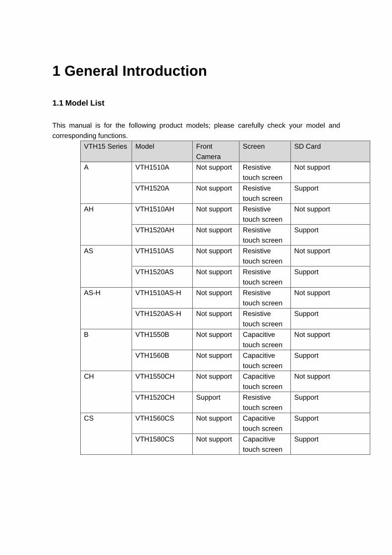
1.1 Model List
This manual is for the following product models; please carefully check your model and
corresponding functions.
VTH15 Series Model Front
Camera
Screen SD Card
A VTH1510A Not support Resistive
touch screen
Not support
VTH1520A Not support Resistive
touch screen
Support
AH VTH1510AH Not support Resistive
touch screen
Not support
VTH1520AH Not support Resistive
touch screen
Support
AS VTH1510AS Not support Resistive
touch screen
Not support
VTH1520AS Not support Resistive
touch screen
Support
AS-H VTH1510AS-H Not support Resistive
touch screen
Not support
VTH1520AS-H Not support Resistive
touch screen
Support
B VTH1550B Not support Capacitive
touch screen
Not support
VTH1560B Not support Capacitive
touch screen
Support
CH VTH1550CH Not support Capacitive
touch screen
Not support
VTH1520CH Support Resistive
touch screen
Support
CS VTH1560CS Not support Capacitive
touch screen
Support
VTH1580CS Not support Capacitive
touch screen
Support
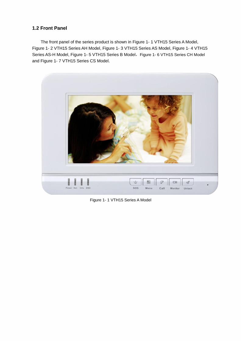
1.2 Front Panel
The front panel of the series product is shown in Figure 1- 1 VTH15 Series A Model,
Figure 1- 2 VTH15 Series AH Model, Figure 1- 3 VTH15 Series AS Model, Figure 1- 4 VTH15
Series AS-H Model, Figure 1- 5 VTH15 Series B Model,Figure 1- 6 VTH15 Series CH Model
and Figure 1- 7 VTH15 Series CS Model.
Figure 1- 1 VTH15 Series A Model
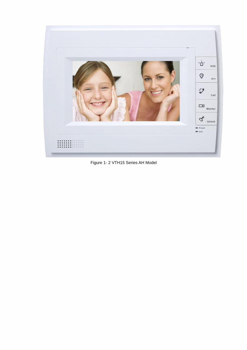
Figure 1- 2 VTH15 Series AH Model
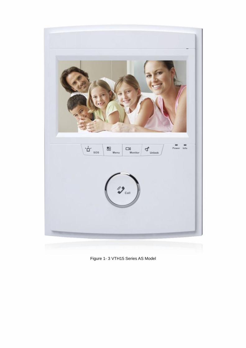
Figure 1- 3 VTH15 Series AS Model

Figure 1- 4 VTH15 Series AS-H Model
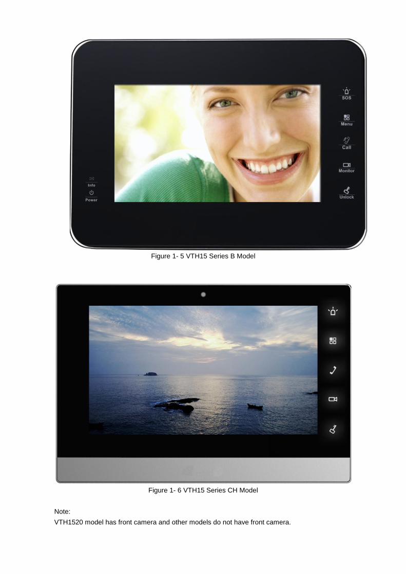
Figure 1- 5 VTH15 Series B Model
Figure 1- 6 VTH15 Series CH Model
Note:
VTH1520 model has front camera and other models do not have front camera.
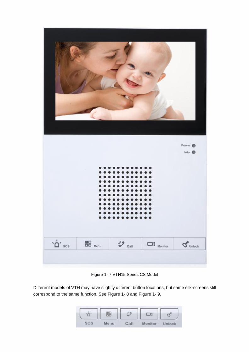
Figure 1- 7 VTH15 Series CS Model
Different models of VTH may have slightly different button locations, but same silk-screens still
correspond to the same function. See Figure 1- 8 and Figure 1- 9.
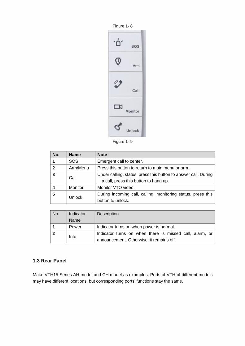
Figure 1- 8
Figure 1- 9
No. Name Note
1 SOS Emergent call to center.
2 Arm/Menu Press this button to return to main menu or arm.
3 Call
Under calling, status, press this button to answer call. During
a call, press this button to hang up.
4 Monitor Monitor VTO video.
5 Unlock
During incoming call, calling, monitoring status, press this
button to unlock.
No. Indicator
Name
Description
1 Power Indicator turns on when power is normal.
2 Info
Indicator turns on when there is missed call, alarm, or
announcement. Otherwise, it remains off.
1.3 Rear Panel
Make VTH15 Series AH model and CH model as examples. Ports of VTH of different models
may have different locations, but corresponding ports’ functions stay the same.
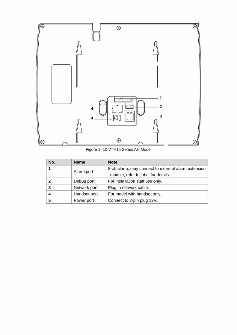
Figure 1- 10 VTH15 Series AH Model
No. Name Note
1 Alarm port
8-ch alarm, may connect to external alarm extension
module, refer to label for details.
2 Debug port For installation staff use only.
3 Network port Plug in network cable.
4 Handset port For model with handset only.
5 Power port Connect to 2-pin plug 12V.
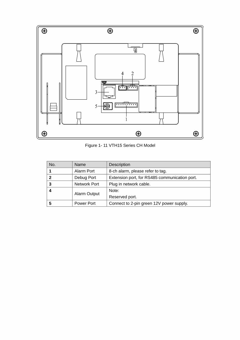
Figure 1- 11 VTH15 Series CH Model
No. Name Description
1 Alarm Port 8-ch alarm, please refer to tag.
2 Debug Port Extension port, for RS485 communication port.
3 Network Port Plug in network cable.
4 Alarm Output
Note:
Reserved port.
5 Power Port Connect to 2-pin green 12V power supply.
2 Product Function
2.1 Basic Function
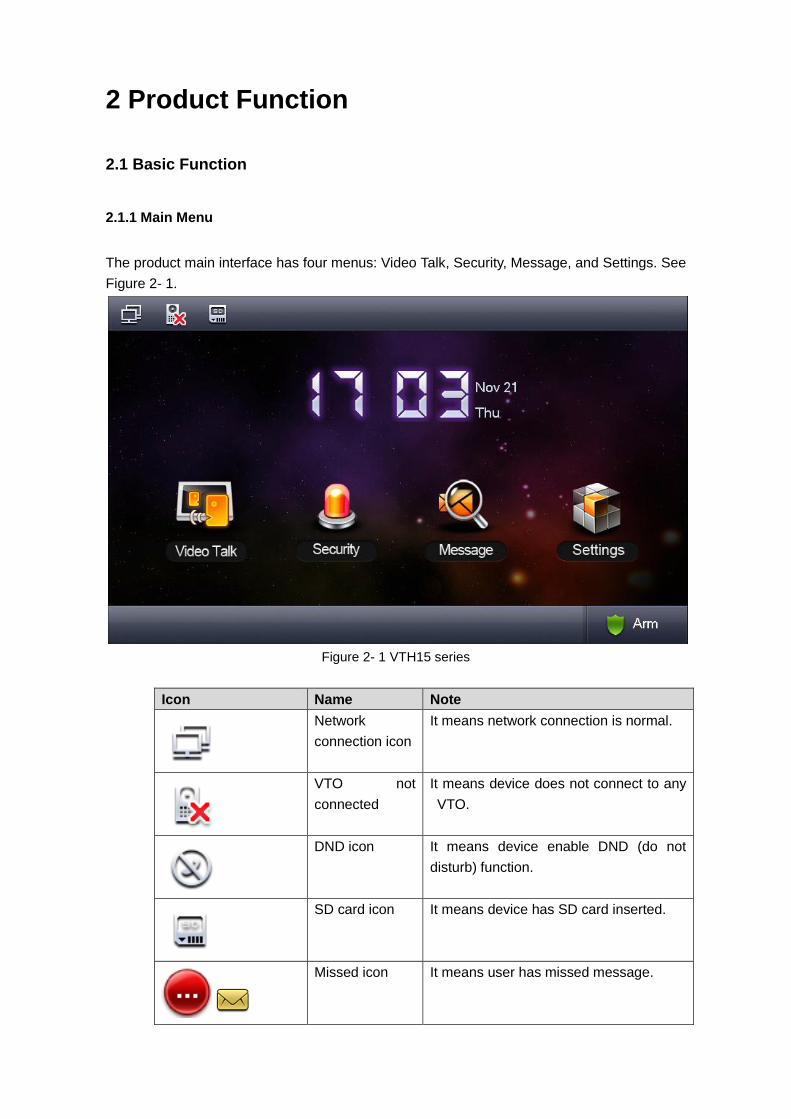
2.1.1 Main Menu
The product main interface has four menus: Video Talk, Security, Message, and Settings. See
Figure 2- 1.
Figure 2- 1 VTH15 series
Icon Name Note
Network
connection icon
It means network connection is normal.
VTO not
connected
It means device does not connect to any
VTO.
DND icon It means device enable DND (do not
disturb) function.
SD card icon It means device has SD card inserted.
Missed icon It means user has missed message.
2.1.2 Video Talk
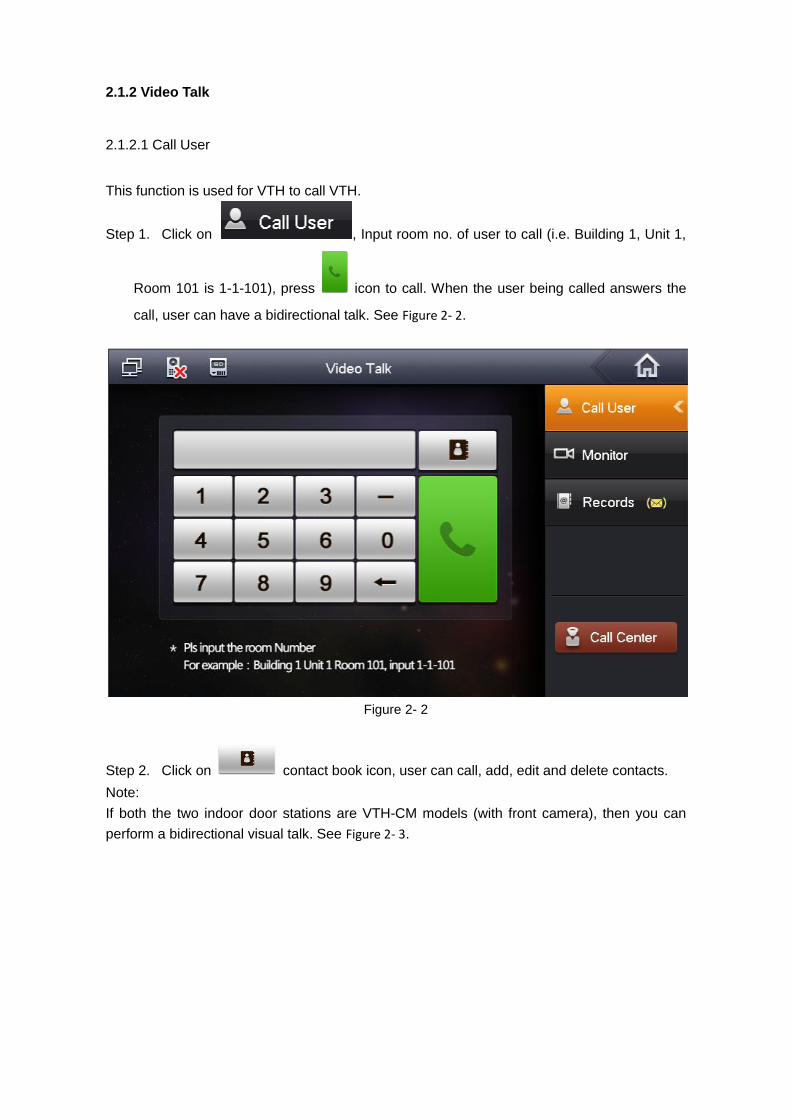
2.1.2.1 Call User
This function is used for VTH to call VTH.
Step 1. Click on , Input room no. of user to call (i.e. Building 1, Unit 1,
Room 101 is 1-1-101), press icon to call. When the user being called answers the
call, user can have a bidirectional talk. See Figure 2- 2.
Figure 2- 2
Step 2. Click on contact book icon, user can call, add, edit and delete contacts.
Note:
If both the two indoor door stations are VTH-CM models (with front camera), then you can
perform a bidirectional visual talk. See Figure 2- 3.
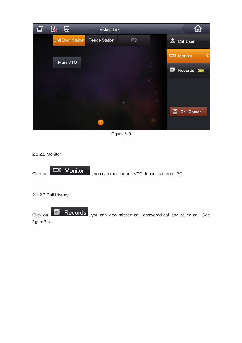
Figure 2- 3
2.1.2.2 Monitor
Click on , you can monitor unit VTO, fence station or IPC.
2.1.2.3 Call History
Click on , you can view missed call, answered call and called call. See
Figure 2- 4.
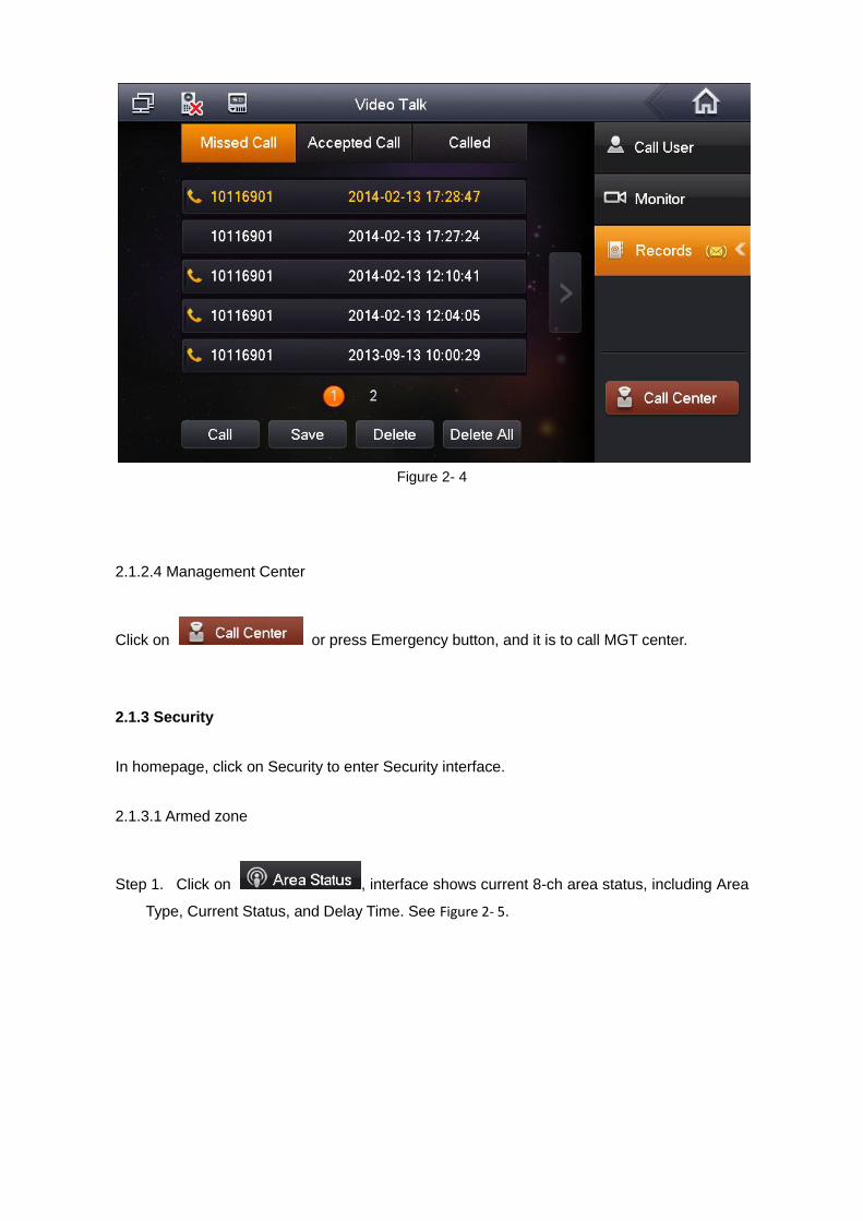
Figure 2- 4
2.1.2.4 Management Center
Click on or press Emergency button, and it is to call MGT center.
2.1.3 Security
In homepage, click on Security to enter Security interface.
2.1.3.1 Armed zone
Step 1. Click on , interface shows current 8-ch area status, including Area
Type, Current Status, and Delay Time. See Figure 2- 5.
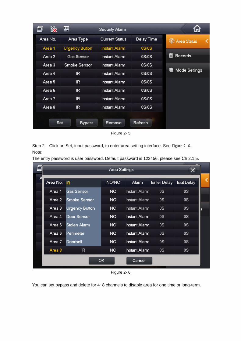
Figure 2- 5
Step 2. Click on Set, input password, to enter area setting interface. See Figure 2- 6.
Note:
The entry password is user password. Default password is 123456, please see Ch 2.1.5.
Figure 2- 6
You can set bypass and delete for 4~8 channels to disable area for one time or long-term.
2.1.3.2 Alarm History
Click on , and it records alarm time, area no., and event.
Meantime, alarm info will be simultaneously uploaded to management platform. When each
channel has alarm, there will be a 15s alarm locally, plus a pop-up alarm interface.
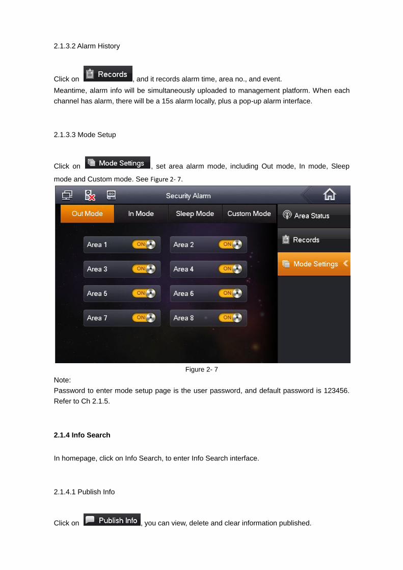
2.1.3.3 Mode Setup
Click on , set area alarm mode, including Out mode, In mode, Sleep
mode and Custom mode. See Figure 2- 7.
Figure 2- 7
Note:
Password to enter mode setup page is the user password, and default password is 123456.
Refer to Ch 2.1.5.
2.1.4 Info Search
In homepage, click on Info Search, to enter Info Search interface.
2.1.4.1 Publish Info
Click on , you can view, delete and clear information published.
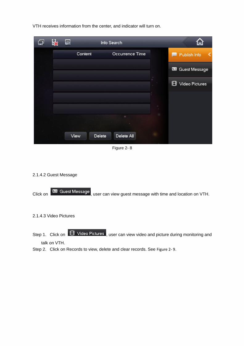
VTH receives information from the center, and indicator will turn on.
Figure 2- 8
2.1.4.2 Guest Message
Click on , user can view guest message with time and location on VTH.
2.1.4.3 Video Pictures
Step 1. Click on , user can view video and picture during monitoring and
talk on VTH.
Step 2. Click on Records to view, delete and clear records. See Figure 2- 9.
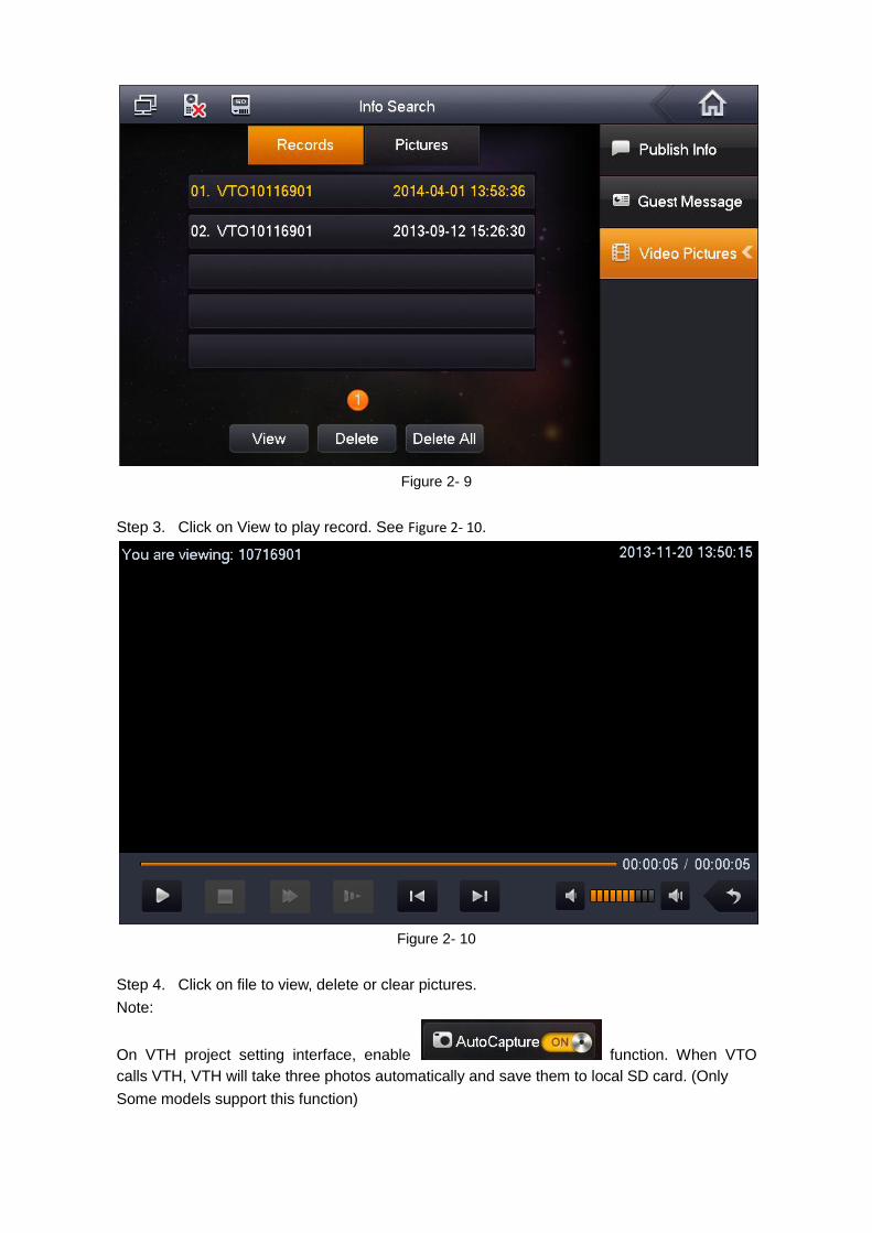
Figure 2- 9
Step 3. Click on View to play record. See Figure 2- 10.
Figure 2- 10
Step 4. Click on file to view, delete or clear pictures.
Note:
On VTH project setting interface, enable function. When VTO
calls VTH, VTH will take three photos automatically and save them to local SD card. (Only
Some models support this function)
2.1.5 System Settings
In System Settings interface, user can set screen brightness, incoming ring, alarm ring, talk
time, DND time and etc. The following introduces the most commonly used functions.
User
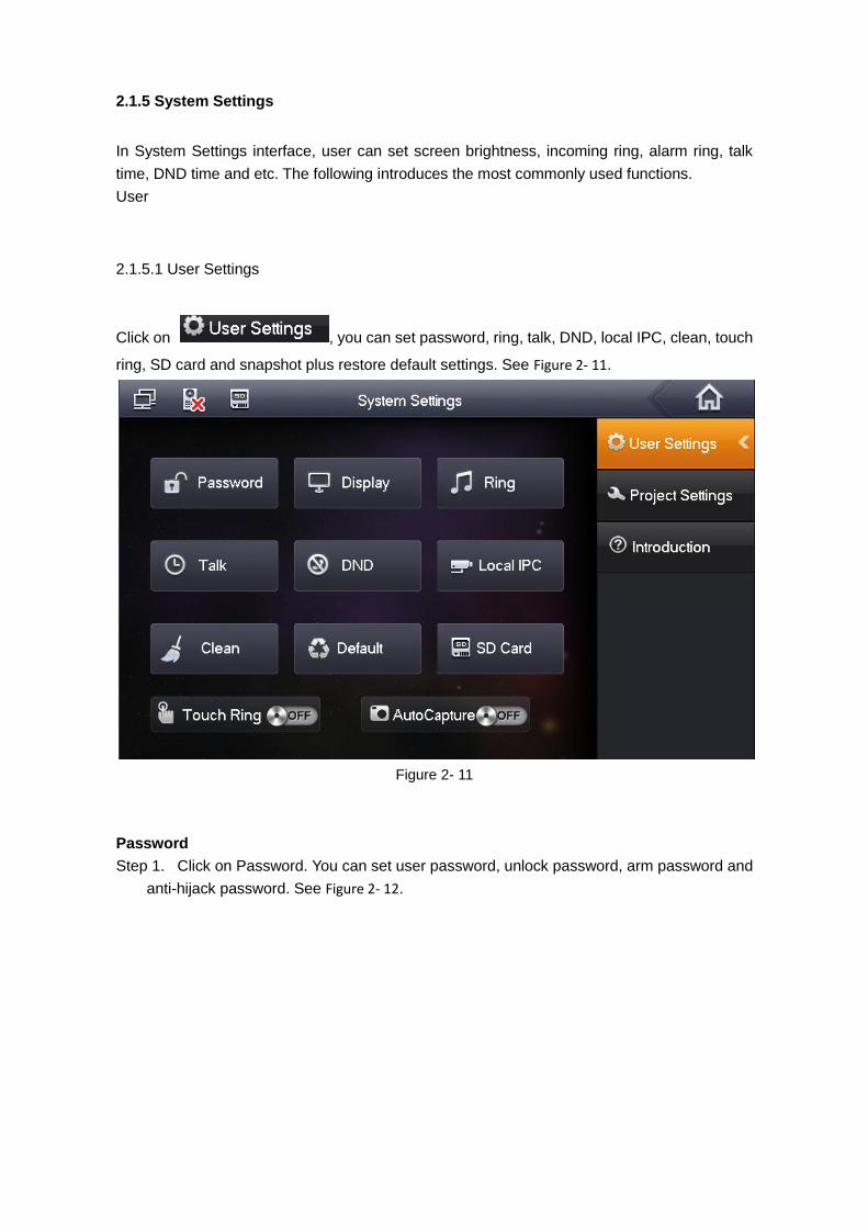
2.1.5.1 User Settings
Click on , you can set password, ring, talk, DND, local IPC, clean, touch
ring, SD card and snapshot plus restore default settings. See Figure 2- 11.
Figure 2- 11
Password
Step 1. Click on Password. You can set user password, unlock password, arm password and
anti-hijack password. See Figure 2- 12.
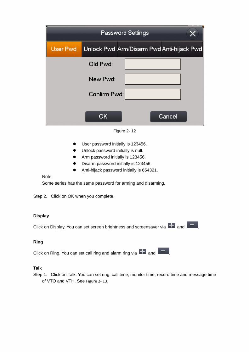
Figure 2- 12
User password initially is 123456.
Unlock password initially is null.
Arm password initially is 123456.
Disarm password initially is 123456.
Anti-hijack password initially is 654321.
Note:
Some series has the same password for arming and disarming.
Step 2. Click on OK when you complete.
Display
Click on Display. You can set screen brightness and screensaver via and .
Ring
Click on Ring. You can set call ring and alarm ring via and .
Talk
Step 1. Click on Talk. You can set ring, call time, monitor time, record time and message time
of VTO and VTH. See Figure 2- 13.
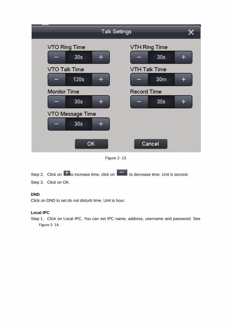
Figure 2- 13
Step 2. Click on to increase time, click on to decrease time. Unit is second.
Step 3. Click on OK.
DND
Click on DND to set do not disturb time. Unit is hour.
Local IPC
Step 1. Click on Local IPC. You can set IPC name, address, username and password. See
Figure 2- 14.
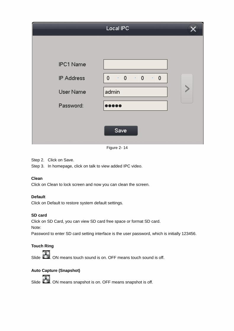
Figure 2- 14
Step 2. Click on Save.
Step 3. In homepage, click on talk to view added IPC video.
Clean
Click on Clean to lock screen and now you can clean the screen.
Default
Click on Default to restore system default settings.
SD card
Click on SD Card, you can view SD card free space or format SD card.
Note:
Password to enter SD card setting interface is the user password, which is initially 123456.
Touch Ring
Slide . ON means touch sound is on. OFF means touch sound is off.
Auto Capture (Snapshot)
Slide . ON means snapshot is on. OFF means snapshot is off.
2.1.5.2 Project Settings
Click on , this function is for installer user only. The entry password is
002236.
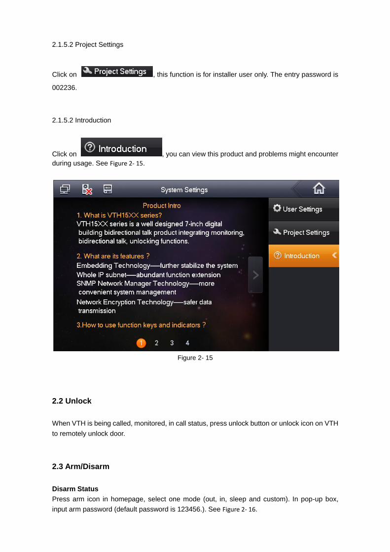
2.1.5.2 Introduction
Click on , you can view this product and problems might encounter
during usage. See Figure 2- 15.
Figure 2- 15
2.2 Unlock
When VTH is being called, monitored, in call status, press unlock button or unlock icon on VTH
to remotely unlock door.
2.3 Arm/Disarm
Disarm Status
Press arm icon in homepage, select one mode (out, in, sleep and custom). In pop-up box,
input arm password (default password is 123456.). See Figure 2- 16.
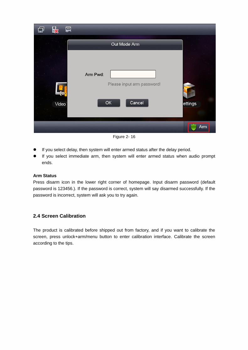
Figure 2- 16
If you select delay, then system will enter armed status after the delay period.
If you select immediate arm, then system will enter armed status when audio prompt
ends.
Arm Status
Press disarm icon in the lower right corner of homepage. Input disarm password (default
password is 123456.). If the password is correct, system will say disarmed successfully. If the
password is incorrect, system will ask you to try again.
2.4 Screen Calibration
The product is calibrated before shipped out from factory, and if you want to calibrate the
screen, press unlock+arm/menu button to enter calibration interface. Calibrate the screen
according to the tips.
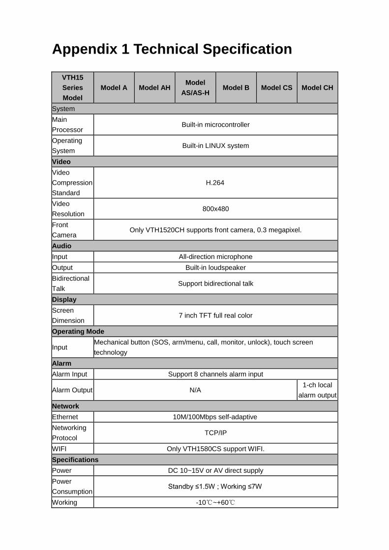
Appendix 1 Technical Specification
VTH15
Series
Model
Model A Model AH Model
AS/AS-H Model B Model CS Model CH
System
Main
Processor Built-in microcontroller
Operating
System Built-in LINUX system
Video
Video
Compression
Standard
H.264
Video
Resolution 800x480
Front
Camera Only VTH1520CH supports front camera, 0.3 megapixel.
Audio
Input All-direction microphone
Output Built-in loudspeaker
Bidirectional
Talk Support bidirectional talk
Display
Screen
Dimension 7 inch TFT full real color
Operating Mode
Input Mechanical button (SOS, arm/menu, call, monitor, unlock), touch screen
technology
Alarm
Alarm Input Support 8 channels alarm input
Alarm Output N/A 1-ch local
alarm output
Network
Ethernet 10M/100Mbps self-adaptive
Networking
Protocol TCP/IP
WIFI Only VTH1580CS support WIFI.
Specifications
Power DC 10~15V or AV direct supply
Power
Consumption Standby ≤1.5W ; Working ≤7W
Working -10℃~+60℃
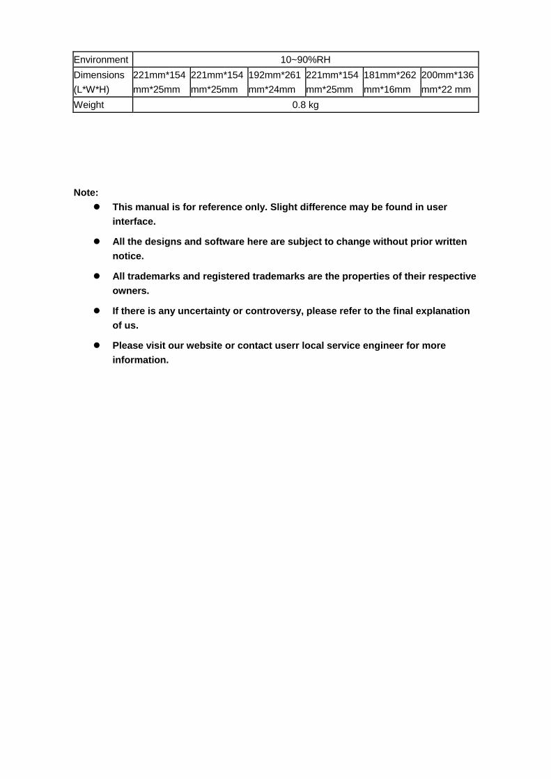
Environment 10~90%RH
Dimensions
(L*W*H)
221mm*154
mm*25mm
221mm*154
mm*25mm
192mm*261
mm*24mm
221mm*154
mm*25mm
181mm*262
mm*16mm
200mm*136
mm*22 mm
Weight 0.8 kg
Note:
This manual is for reference only. Slight difference may be found in user
interface.
All the designs and software here are subject to change without prior written
notice.
All trademarks and registered trademarks are the properties of their respective
owners.
If there is any uncertainty or controversy, please refer to the final explanation
of us.
Please visit our website or contact userr local service engineer for more
information.