abstract sd card standard
TRANSCRIPT
Application NoteSecure Digital Card Interface for the MSP430
F. FoustDept. of Electrical and Computer Engineering
Abstract
Secure Digital (SD) cards are removable flash-based storage devices that are gaining in popularity in smallconsumer devices such as digital cameras, PDAs, and portable music devices. Their small size, relative simplicity,low power consumption, and low cost make them an ideal solution for many applications.
This application note describes the implementation of an SD Card interface for the Texas Instruments MSP430,a low-power 16-bit microcontroller [4]. This interface, combined with the MSP430, can form the foundation fora low-cost, long-life data logger or media player or recorder.
SD Card Standard
The SD card standard is a standard for removable memory storage designed and licensed by the SD CardAssociation [3]. The SD Card standard is largely a collaborative effort by three manufacturers, Toshiba, SanDisk,and MEI [2] and grew out of an older standard, MultiMediaCard (MMC). The card form factor, electrical interface,and protocol are all part of the SD Card specification. The SD standard is not limited to removable memorystorage devices and has been adapted to many different classes of devices, including 802.11 cards, bluetoothdevices, and modems [3].
Comparison with Other Technologies
SD is one of many different types of removable memory storage devices. Among the other competing standardsare CF, CF+, Sony Memory Stick, and USB. These devices all perform similar functions, but differ widely inform factors, complexity, and power consumption.
SD Cards measure only 32x24 mm. This is very small compared to most competing technologies, but is both anadvantage and a disadvantage, since the small size and weight requirements cannot accommodate microdrives.However, if size is a significant design consideration, SD is an ideal choice.
The SD Card electrical interface is relatively simple, requiring at most only 6 wires for communications, whilestill supporting data rates in the Mbps range. Compared to USB and CF/CF+, the SD physical interface is verysimple, a strong consideration if interface complexity is a concern.
SD Cards typically draw no more than 100 mA of current while active, generally less than that drawn by CF orUSB devices. If power consumption is important, SD again is a good choice.
SD Electrical Interface
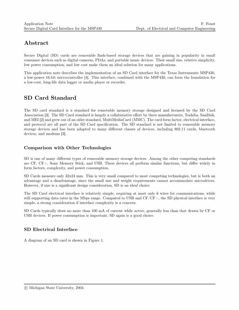
A diagram of an SD card is shown in Figure 1.
c© Michigan State University, 2004
Application NoteSecure Digital Card Interface for the MSP430
F. FoustDept. of Electrical and Computer Engineering
9
4 61 2 3 5 7 8
Figure 1: SD Card Diagram [2].
Table 1 lists the pin assignments for the SD Card.
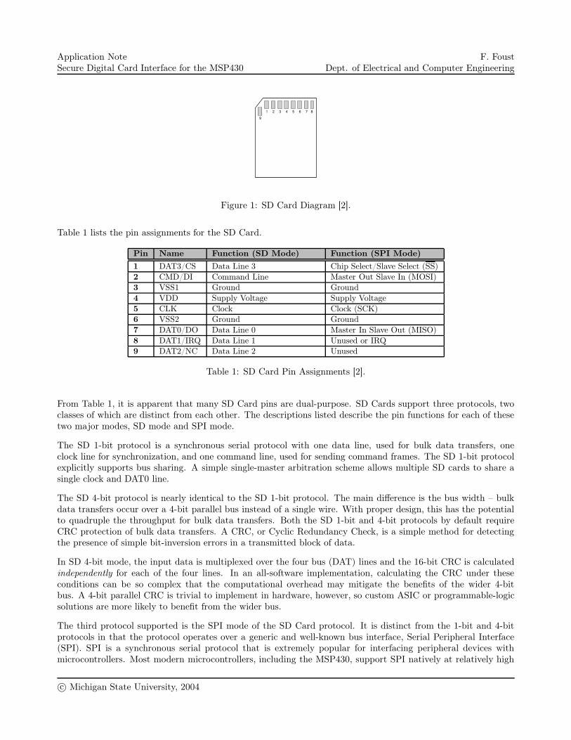
Pin Name Function (SD Mode) Function (SPI Mode)
1 DAT3/CS Data Line 3 Chip Select/Slave Select (SS)
2 CMD/DI Command Line Master Out Slave In (MOSI)
3 VSS1 Ground Ground
4 VDD Supply Voltage Supply Voltage
5 CLK Clock Clock (SCK)
6 VSS2 Ground Ground
7 DAT0/DO Data Line 0 Master In Slave Out (MISO)
8 DAT1/IRQ Data Line 1 Unused or IRQ
9 DAT2/NC Data Line 2 Unused
Table 1: SD Card Pin Assignments [2].
From Table 1, it is apparent that many SD Card pins are dual-purpose. SD Cards support three protocols, twoclasses of which are distinct from each other. The descriptions listed describe the pin functions for each of thesetwo major modes, SD mode and SPI mode.
The SD 1-bit protocol is a synchronous serial protocol with one data line, used for bulk data transfers, oneclock line for synchronization, and one command line, used for sending command frames. The SD 1-bit protocolexplicitly supports bus sharing. A simple single-master arbitration scheme allows multiple SD cards to share asingle clock and DAT0 line.
The SD 4-bit protocol is nearly identical to the SD 1-bit protocol. The main difference is the bus width – bulkdata transfers occur over a 4-bit parallel bus instead of a single wire. With proper design, this has the potentialto quadruple the throughput for bulk data transfers. Both the SD 1-bit and 4-bit protocols by default requireCRC protection of bulk data transfers. A CRC, or Cyclic Redundancy Check, is a simple method for detectingthe presence of simple bit-inversion errors in a transmitted block of data.
In SD 4-bit mode, the input data is multiplexed over the four bus (DAT) lines and the 16-bit CRC is calculatedindependently for each of the four lines. In an all-software implementation, calculating the CRC under theseconditions can be so complex that the computational overhead may mitigate the benefits of the wider 4-bitbus. A 4-bit parallel CRC is trivial to implement in hardware, however, so custom ASIC or programmable-logicsolutions are more likely to benefit from the wider bus.
The third protocol supported is the SPI mode of the SD Card protocol. It is distinct from the 1-bit and 4-bitprotocols in that the protocol operates over a generic and well-known bus interface, Serial Peripheral Interface(SPI). SPI is a synchronous serial protocol that is extremely popular for interfacing peripheral devices withmicrocontrollers. Most modern microcontrollers, including the MSP430, support SPI natively at relatively high
c© Michigan State University, 2004
Application NoteSecure Digital Card Interface for the MSP430
F. FoustDept. of Electrical and Computer Engineering
data rates. The SPI communications mode supports only a subset of the full SD Card protocol. However, most ofthe unsupported command sets are simply not needed in SPI mode. A fully-functional SD Card implementationcan be realized using only SPI.
This flexibility of electrical interfaces is a significant advantage to a designer. A designer may opt for a fastparallel interface, or depending on the application, may prefer a slower implementation using SPI. Due to thepopularity of the SPI protocol and its efficient implementation on the MSP430, this application note covers onlythe SPI mode of the SD Card protocol. Minor differences in the initialization sequence exist between the twomajor modes. For more information, the interested reader should consult the full SD Card Specification, availablefrom the SD Card Association [3].
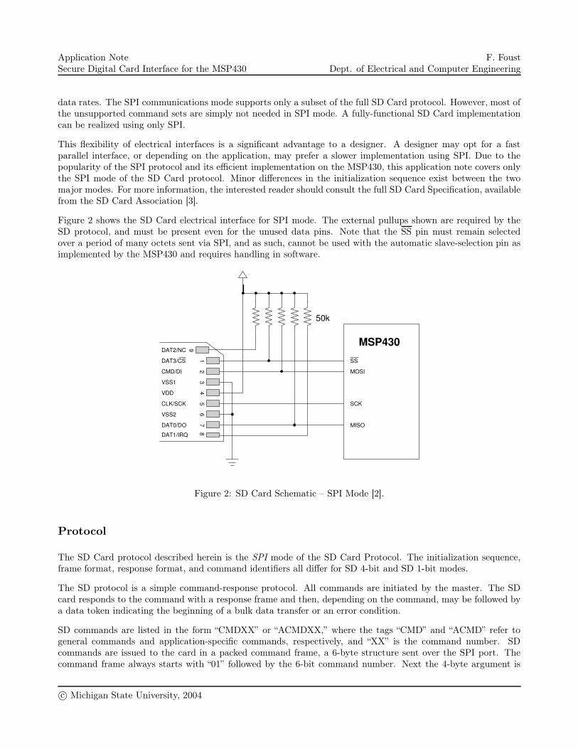
Figure 2 shows the SD Card electrical interface for SPI mode. The external pullups shown are required by theSD protocol, and must be present even for the unused data pins. Note that the SS pin must remain selectedover a period of many octets sent via SPI, and as such, cannot be used with the automatic slave-selection pin asimplemented by the MSP430 and requires handling in software.
50k
MOSI
SCK
MISO
MSP430
46
12
35
78
9DAT2/NC
DAT3/CS
CMD/DI
VSS1
VDD
CLK/SCK
VSS2
DAT0/DO
DAT1/IRQ
SS
Figure 2: SD Card Schematic – SPI Mode [2].
Protocol
The SD Card protocol described herein is the SPI mode of the SD Card Protocol. The initialization sequence,frame format, response format, and command identifiers all differ for SD 4-bit and SD 1-bit modes.
The SD protocol is a simple command-response protocol. All commands are initiated by the master. The SDcard responds to the command with a response frame and then, depending on the command, may be followed bya data token indicating the beginning of a bulk data transfer or an error condition.
SD commands are listed in the form “CMDXX” or “ACMDXX,” where the tags “CMD” and “ACMD” refer togeneral commands and application-specific commands, respectively, and “XX” is the command number. SDcommands are issued to the card in a packed command frame, a 6-byte structure sent over the SPI port. Thecommand frame always starts with “01” followed by the 6-bit command number. Next the 4-byte argument is
c© Michigan State University, 2004
Application NoteSecure Digital Card Interface for the MSP430
F. FoustDept. of Electrical and Computer Engineering
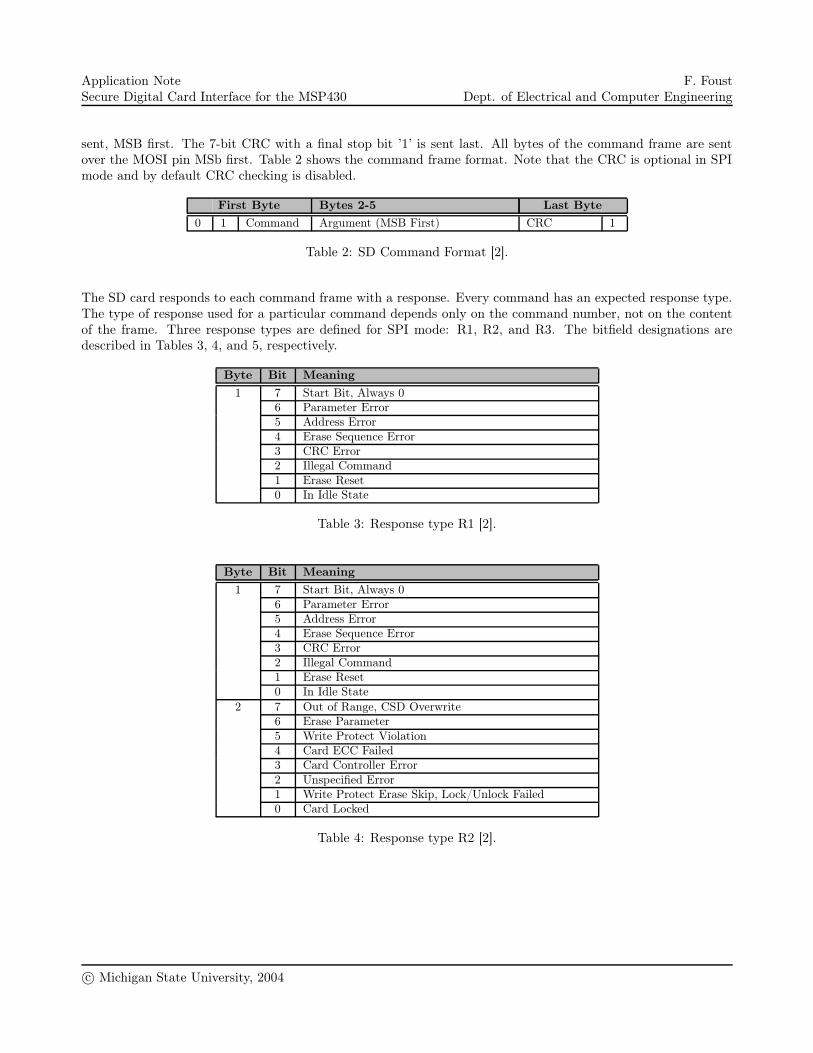
sent, MSB first. The 7-bit CRC with a final stop bit ’1’ is sent last. All bytes of the command frame are sentover the MOSI pin MSb first. Table 2 shows the command frame format. Note that the CRC is optional in SPImode and by default CRC checking is disabled.
First Byte Bytes 2-5 Last Byte
0 1 Command Argument (MSB First) CRC 1
Table 2: SD Command Format [2].
The SD card responds to each command frame with a response. Every command has an expected response type.The type of response used for a particular command depends only on the command number, not on the contentof the frame. Three response types are defined for SPI mode: R1, R2, and R3. The bitfield designations aredescribed in Tables 3, 4, and 5, respectively.
Byte Bit Meaning
1 7 Start Bit, Always 06 Parameter Error5 Address Error4 Erase Sequence Error3 CRC Error2 Illegal Command1 Erase Reset0 In Idle State
Table 3: Response type R1 [2].
Byte Bit Meaning
1 7 Start Bit, Always 06 Parameter Error5 Address Error4 Erase Sequence Error3 CRC Error2 Illegal Command1 Erase Reset0 In Idle State
2 7 Out of Range, CSD Overwrite6 Erase Parameter5 Write Protect Violation4 Card ECC Failed3 Card Controller Error2 Unspecified Error1 Write Protect Erase Skip, Lock/Unlock Failed0 Card Locked
Table 4: Response type R2 [2].
c© Michigan State University, 2004
Application NoteSecure Digital Card Interface for the MSP430
F. FoustDept. of Electrical and Computer Engineering
Byte Bit Meaning
1 7 Start Bit, Always 06 Parameter Error5 Address Error4 Erase Sequence Error3 CRC Error2 Illegal Command1 Erase Reset0 In Idle State
2-5 All Operating Condition Register, MSB First
Table 5: Response type R3 [2].
Bulk data transfers provide a mechanism to efficiently transfer large amounts of data to and from the SD Card.The normal command-response structure only allows for the exchange of small amounts of data in fixed sizes,while bulk data may be of any arbitrary size.
When a bulk data command is issued to the card, the card responds normally with one of the three standardresponse types. Then the bulk transfer starts with a data token, followed by the bulk data itself, and completeswith a 16-bit CRC [2].
For a block read or write, the block transfer is preceded by a start block token, a constant “11111110.” Thisis followed by a block of data (typically 512 bytes), and then followed by a 16-bit CRC [2]. The CRC is notcalculated and is ignored in this implementation.
After every card write, the card will return a 1-byte token indicating the status of the operation. The responsetoken is “XXX0AAA1,” where XXX are don’t cares and AAA indicates the status, if any. “010” indicates thedata was accepted. “101” indicates the data was rejected because of a CRC error. “110” indicates the data wasrejected because of a write error [2].
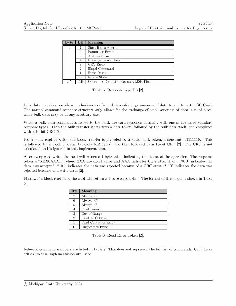
Finally, if a block read fails, the card will return a 1-byte error token. The format of this token is shown in Table6.
Bit Meaning
7 Always ’0’
6 Always ’0’
5 Always ’0’
4 Card Locked
3 Out of Range
2 Card ECC Failed
1 Card Controller Error
0 Unspecified Error
Table 6: Read Error Token [2].
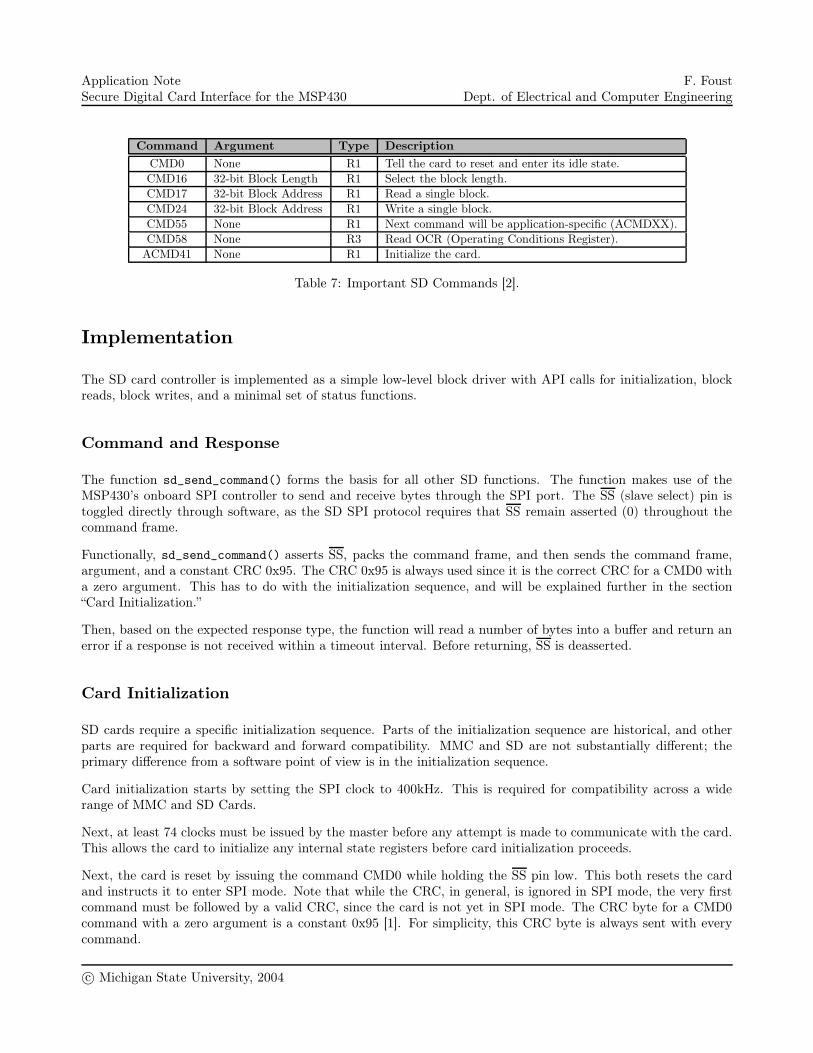
Relevant command numbers are listed in table 7. This does not represent the full list of commands. Only thosecritical to this implementation are listed.
c© Michigan State University, 2004
Application NoteSecure Digital Card Interface for the MSP430
F. FoustDept. of Electrical and Computer Engineering
Command Argument Type Description
CMD0 None R1 Tell the card to reset and enter its idle state.
CMD16 32-bit Block Length R1 Select the block length.
CMD17 32-bit Block Address R1 Read a single block.
CMD24 32-bit Block Address R1 Write a single block.
CMD55 None R1 Next command will be application-specific (ACMDXX).
CMD58 None R3 Read OCR (Operating Conditions Register).
ACMD41 None R1 Initialize the card.
Table 7: Important SD Commands [2].
Implementation
The SD card controller is implemented as a simple low-level block driver with API calls for initialization, blockreads, block writes, and a minimal set of status functions.
Command and Response
The function sd_send_command() forms the basis for all other SD functions. The function makes use of theMSP430’s onboard SPI controller to send and receive bytes through the SPI port. The SS (slave select) pin istoggled directly through software, as the SD SPI protocol requires that SS remain asserted (0) throughout thecommand frame.
Functionally, sd_send_command() asserts SS, packs the command frame, and then sends the command frame,argument, and a constant CRC 0x95. The CRC 0x95 is always used since it is the correct CRC for a CMD0 witha zero argument. This has to do with the initialization sequence, and will be explained further in the section“Card Initialization.”
Then, based on the expected response type, the function will read a number of bytes into a buffer and return anerror if a response is not received within a timeout interval. Before returning, SS is deasserted.
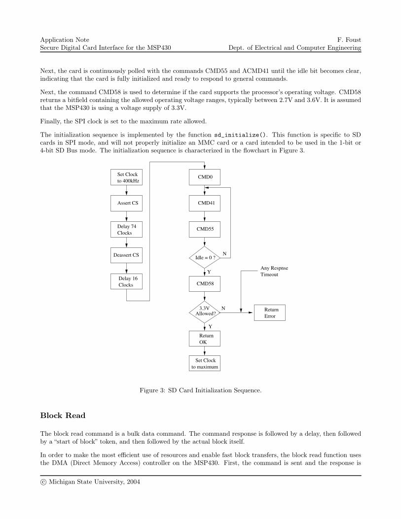
Card Initialization
SD cards require a specific initialization sequence. Parts of the initialization sequence are historical, and otherparts are required for backward and forward compatibility. MMC and SD are not substantially different; theprimary difference from a software point of view is in the initialization sequence.
Card initialization starts by setting the SPI clock to 400kHz. This is required for compatibility across a widerange of MMC and SD Cards.
Next, at least 74 clocks must be issued by the master before any attempt is made to communicate with the card.This allows the card to initialize any internal state registers before card initialization proceeds.
Next, the card is reset by issuing the command CMD0 while holding the SS pin low. This both resets the cardand instructs it to enter SPI mode. Note that while the CRC, in general, is ignored in SPI mode, the very firstcommand must be followed by a valid CRC, since the card is not yet in SPI mode. The CRC byte for a CMD0command with a zero argument is a constant 0x95 [1]. For simplicity, this CRC byte is always sent with everycommand.
c© Michigan State University, 2004
Application NoteSecure Digital Card Interface for the MSP430
F. FoustDept. of Electrical and Computer Engineering
Next, the card is continuously polled with the commands CMD55 and ACMD41 until the idle bit becomes clear,indicating that the card is fully initialized and ready to respond to general commands.
Next, the command CMD58 is used to determine if the card supports the processor’s operating voltage. CMD58returns a bitfield containing the allowed operating voltage ranges, typically between 2.7V and 3.6V. It is assumedthat the MSP430 is using a voltage supply of 3.3V.
Finally, the SPI clock is set to the maximum rate allowed.
The initialization sequence is implemented by the function sd_initialize(). This function is specific to SDcards in SPI mode, and will not properly initialize an MMC card or a card intended to be used in the 1-bit or4-bit SD Bus mode. The initialization sequence is characterized in the flowchart in Figure 3.
Idle = 0 ?
CMD0
CMD41
Allowed?3.3V Return
Error
Any RespnseTimeout
Assert CS
Delay 74Clocks
Deassert CS
Delay 16Clocks
Set Clockto 400kHz
OKReturn
Set Clockto maximum
Y
N
Y
N
CMD55
CMD58
Figure 3: SD Card Initialization Sequence.
Block Read
The block read command is a bulk data command. The command response is followed by a delay, then followedby a “start of block” token, and then followed by the actual block itself.
In order to make the most efficient use of resources and enable fast block transfers, the block read function usesthe DMA (Direct Memory Access) controller on the MSP430. First, the command is sent and the response is
c© Michigan State University, 2004
Application NoteSecure Digital Card Interface for the MSP430
F. FoustDept. of Electrical and Computer Engineering
received. Then, the function waits until the start token is received. When it is received, the function starts aDMA transfer.
Since SPI requires that a byte be sent for a byte to be received, two DMA units are used to complete the transfer.
DMA0 is triggered by a UART receive. The source for the DMA transfer is the USART receive buffer, U0RXBUF.The source is set to byte-wide, no increment. The destination for the DMA transfer is the data buffer. Thedestination is set to byte-wide, with an increment. The count is fixed at 512, the default block size for a typicalSD card.
DMA1 is also triggered by a UART receive. The source for this register is a constant 0xFF (the idle bus condition).The output is the USART transmit buffer, U0TXBUF.
DMA priorities ensure that a byte will be received before a new 0xFF (idle byte) is sent. Since both DMA unitsuse the same trigger, DMA0 will always be serviced before DMA1.
Finally, the receive and transmit interrupt flags are reset and the entire block transfer is triggered by manuallysending a single idle byte.
The function sd_read_block() implements the block read. The function will return immediately and normal pro-gram execution can continue while the block transfer finishes. sd_wait_notbusy() can be used to synchronouslywait for any pending block transfers to finish.
Block Write
The block write is similar to the block read function in that it uses a DMA transfer and also starts with a datatoken. However, since no bytes need to be received during the block transfer, the block transfer only requires oneDMA trigger.
DMA0 is triggered by a UART send. The destination for the DMA transfer is the USART receive buffer,U0RXBUF. The destination is set to byte-wide, no increment. The source for the DMA transfer is the databuffer. The source is set to byte-wide, with an increment. The count is fixed at 512, the default block size for atypical SD card.
Finally, the receive and transmit interrupt flags are reset and the entire block transfer is triggered by manuallysending a single idle byte.
The function sd_write_block() implements the block write. The function will return immediately and normalprogram execution can continue while the block transfer finishes. sd_wait_notbusy() can be used to syn-chronously wait for any pending block transfers to finish.
Summary and Conclusions
SD Cards offer a cost-effective way to store large amounts of data in a removable memory storage device. Thesimplicity of the SD Card protocol and the flexibility in interfacing with these devices makes them ideal for usewith small microcontrollers.
Combined with the low-cost, low-power TI MSP430 and its advanced features like onboard DMA and SPI, afast and low-overhead complete data logging solution can be implemented quickly and inexpensively. Additionalapplication-level support for a filesystem such as FAT16 can extend the usefulness of this solution even further.
c© Michigan State University, 2004
Application NoteSecure Digital Card Interface for the MSP430
F. FoustDept. of Electrical and Computer Engineering
Appendix A - main.c
#include <msp430x16x.h>
#include "main.h"
#include "sd.h"
#include "spi.h"
static unsigned char sd_buffer[512];
static sd_context_t sdc;
void main(void)
{
int j, ok;
ok = 0;
/* Stop the watchdog timer */
WDTCTL = WDTPW | WDTHOLD;
/* Set some reasonable values for the timeouts. */
sdc.timeout_write = PERIPH_CLOCKRATE/8;
sdc.timeout_read = PERIPH_CLOCKRATE/20;
sdc.busyflag = 0;
for (j=0; j<SD_INIT_TRY && ok != 1; j++)
{
ok = do_sd_initialize(&sdc);
}
/* Read in the first block on the SD Card */
if (ok == 1)
{
sd_read_block (&sdc, 0, sd_buffer);
sd_wait_notbusy (&sdc);
}
/* Wait forever */
while (1) { }
}
int do_sd_initialize (sd_context_t *sdc)
{
/* Initialize the SPI controller */
spi_initialize();
/* Start out with a slow SPI clock, 400kHz, as required by the SD spec
(for MMC compatibility). */
spi_set_divisor(PERIPH_CLOCKRATE/400000);
/* Initialization OK? */
if (sd_initialize(sdc) != 1)
return 0;
/* Set the maximum SPI clock rate possible */
spi_set_divisor(2);
return 1;
}
c© Michigan State University, 2004
Application NoteSecure Digital Card Interface for the MSP430
F. FoustDept. of Electrical and Computer Engineering
Appendix B - main.h
#ifndef MAIN_H
#define MAIN_H
#include "sdcomm_spi.h"
/* Peripheral clock rate, in Hz, used for timing. */
#define PERIPH_CLOCKRATE 8000000
int do_sd_initialize (sd_context_t *sdc);
#endif
Appendix C - sd.c
#include <msp430x16x.h>
#include "main.h"
#include "sd.h"
#include "sdcomm_spi.h"
#include "spi.h"
static unsigned char response[5];
static unsigned char argument[4];
int sd_card_present()
{
return (!(P3IN & 0x01));
}
/* This function initializes the SD card. It returns 1 if
initialization was successful, 0 otherwise.
sd_context_t *sdc -- pointer to a data structure containing
information about the card. For now, the
timeouts MUST be specified in advance. This
function does not yet calculate them from the
card data.
*/
int sd_initialize(sd_context_t *sdc)
{
char i, j;
/* SPI SD initialization sequence:
* CMD0
* CMD55
* ACMD41
* CMD58
* (Note there is no CMD2 or CMD3 in SPI mode. These
* instructions are devoted to addressing on the SD bus.)
*
* SD memory card SD initialization sequence:
* CMD0
* CMD55
* ACMD41
* CMD2
* CMD3
*/
c© Michigan State University, 2004
Application NoteSecure Digital Card Interface for the MSP430
F. FoustDept. of Electrical and Computer Engineering
sdc->busyflag = 0;
for (i=0; i<4; i++)
argument[i] = 0;
/* Delay for at least 74 clock cycles. This means to actually
* *clock* out at least 74 clock cycles with no data present on
* the clock. In SPI mode, send at least 10 idle bytes (0xFF). */
spi_cs_assert();
sd_delay(100);
spi_cs_deassert();
sd_delay(2);
/* Put the card in the idle state */
if (sd_send_command(sdc, CMD0, CMD0_R, response, argument) == 0)
return 0;
/* Now wait until the card goes idle. Retry at most SD_IDLE_WAIT_MAX
times */
j = 0;
do
{
j++;
/* Flag the next command as an application-specific command */
if (sd_send_command(sdc, CMD55, CMD55_R, response, argument) == 1)
{
/* Tell the card to send its OCR */
sd_send_command(sdc, ACMD41, ACMD41_R, response, argument);
}
else
{
/* No response, bail early */
j = SD_IDLE_WAIT_MAX;
}
}
while ((response[0] & MSK_IDLE) == MSK_IDLE && j < SD_IDLE_WAIT_MAX);
/* As long as we didn’t hit the timeout, assume we’re OK. */
if (j >= SD_IDLE_WAIT_MAX)
return 0;
if (sd_send_command(sdc, CMD58, CMD58_R, response, argument) == 0)
return 0;
/* At a very minimum, we must allow 3.3V. */
if ((response[2] & MSK_OCR_33) != MSK_OCR_33)
return 0;
/* Set the block length */
if (sd_set_blocklen (sdc, SD_BLOCKSIZE) != 1)
return 0;
/* If we got this far, initialization was OK. */
return 1;
}
/* This function reads a single block from the SD card at block
blockaddr. The buffer must be preallocated. Returns 1 if the
command was successful, zero otherwise.
This is an ASYNCHRONOUS call. The transfer will not be complete
c© Michigan State University, 2004
Application NoteSecure Digital Card Interface for the MSP430
F. FoustDept. of Electrical and Computer Engineering
when the function returns. If you want to explicitly wait until
any pending transfers are finished, use the command
sd_wait_notbusy(sdc).
sd_context_t *sdc -- a pointer to an sd device context structure,
populated by the function sd_initialize()
u32 blockaddr -- The block address to read from the card.
This is a block address, not a linear address.
unsigned char *data -- The data, a pointer to an array of unsigned
chars.
*/
int sd_read_block (sd_context_t *sdc, u32 blockaddr,
unsigned char *data)
{
unsigned long int i = 0;
unsigned char tmp;
unsigned char blank = 0xFF;
/* Adjust the block address to a linear address */
blockaddr <<= SD_BLOCKSIZE_NBITS;
/* Wait until any old transfers are finished */
sd_wait_notbusy (sdc);
/* Pack the address */
sd_packarg(argument, blockaddr);
/* Need to add size checking */
if (sd_send_command(sdc, CMD17, CMD17_R, response, argument) == 0)
return 0;
/* Check for an error, like a misaligned read */
if (response[0] != 0)
return 0;
/* Re-assert CS to continue the transfer */
spi_cs_assert();
/* Wait for the token */
i=0;
do
{
tmp = spi_rcv_byte();
i++;
}
while ((tmp == 0xFF) && i < sdc->timeout_read );
if ((tmp & MSK_TOK_DATAERROR) == 0)
{
/* Clock out a byte before returning */
spi_send_byte(0xFF);
/* The card returned an error response. Bail and return 0 */
return 0;
}
/* Prime the interrupt flags so things happen in the correct order. */
IFG1 &= ~URXIFG0;
IFG1 &= ~UTXIFG0;
/* Get the block */
/* Source DMA address: receive register. */
DMA0SA = U0RXBUF_;
/* Destination DMA address: the user data buffer. */
DMA0DA = (unsigned short)data;
c© Michigan State University, 2004
Application NoteSecure Digital Card Interface for the MSP430
F. FoustDept. of Electrical and Computer Engineering
/* The size of the block to be transferred */
DMA0SZ = SD_BLOCKSIZE;
/* Configure the DMA transfer*/
DMA0CTL =
DMADT_0 | /* Single transfer mode */
DMASBDB | /* Byte mode */
DMAEN | /* Enable DMA */
DMADSTINCR1 | DMADSTINCR0; /* Increment the destination address */
/* We depend on the DMA priorities here. Both triggers occur at
the same time, since the source is identical. DMA0 is handled
first, and retrieves the byte. DMA1 is triggered next, and
sends the next byte. */
/* Source DMA address: constant 0xFF (don’t increment)*/
DMA1SA = (unsigned short)␣
/* Destination DMA address: the transmit buffer. */
DMA1DA = U0TXBUF_;
/* Increment the destination address */
/* The size of the block to be transferred */
DMA1SZ = SD_BLOCKSIZE-1;
/* Configure the DMA transfer*/
DMA1CTL =
DMADT_0 | /* Single transfer mode */
DMASBDB | /* Byte mode */
DMAEN; /* Enable DMA */
/* DMA trigger is UART receive for both DMA0 and DMA1 */
DMACTL0 = DMA0TSEL_3 | DMA1TSEL_3;
/* Kick off the transfer by sending the first byte */
U0TXBUF = 0xFF;
return 1;
}
/* This function writes a single block to the SD card at block
blockaddr. Returns 1 if the command was successful, zero
otherwise.
This is an ASYNCHRONOUS call. The transfer will not be complete
when the function returns. If you want to explicitly wait until
any pending transfers are finished, use the command
sd_wait_notbusy(sdc).
sd_context_t *sdc -- a pointer to an sd device context structure,
populated by the function sd_initialize()
u32 blockaddr -- The block address to read from the card.
This is a block address, not a linear address.
unsigned char *data -- The data, a pointer to an array of unsigned
chars.
*/
int sd_write_block (sd_context_t *sdc, u32 blockaddr,
unsigned char *data)
{
/* Adjust the block address to a linear address */
blockaddr <<= SD_BLOCKSIZE_NBITS;
/* Wait until any old transfers are finished */
sd_wait_notbusy (sdc);
/* Pack the address */
sd_packarg(argument, blockaddr);
if (sd_send_command(sdc, CMD24, CMD24_R, response, argument) == 0)
c© Michigan State University, 2004
Application NoteSecure Digital Card Interface for the MSP430
F. FoustDept. of Electrical and Computer Engineering
return 0;
/* Check for an error, like a misaligned write */
if (response[0] != 0)
return 0;
/* Re-assert CS to continue the transfer */
spi_cs_assert();
/* The write command needs an additional 8 clock cycles before
* the block write is started. */
spi_rcv_byte();
/* Clear any pending flags */
IFG1 &= ~(URXIFG0 | UTXIFG0);
/* Get the block */
/* Source DMA address: the data buffer. */
DMA0SA = (unsigned short)data;
/* Destination DMA address: the UART send register. */
DMA0DA = U0TXBUF_;
/* The size of the block to be transferred */
DMA0SZ = SD_BLOCKSIZE;
/* Configure the DMA transfer*/
DMA0CTL =
DMADT_0 | /* Single transfer mode */
DMASBDB | /* Byte mode */
DMAEN | /* Enable DMA */
DMASRCINCR1 | DMASRCINCR0; /* Increment the source address */
/* DMA trigger is UART send */
DMACTL0 = DMA0TSEL_3;
/* Kick off the transfer by sending the first byte, the "start block"
* token */
U0TXBUF = SD_TOK_WRITE_STARTBLOCK;
/* Signal that the card may be busy, so any subsequent commands
should wait for the busy signalling to end (indicated by a
nonzero response). */
sdc->busyflag = 1;
return 1;
}
/* This function synchronously waits until any pending block transfers
are finished. If your program needs to ensure a block has finished
transferring, call this function.
Note that sd_read_block() and sd_write_block() already call this
function internally before attempting a new transfer, so there are
only two times when a user would need to use this function.
1) When the processor will be shutting down. All pending
writes should be finished first.
2) When the user needs the results of an sd_read_block() call
right away.
*/
void sd_wait_notbusy (sd_context_t *sdc)
{
/* Just twiddle our thumbs until the transfer’s done */
while ((DMA0CTL & DMAEN) != 0) { }
c© Michigan State University, 2004
Application NoteSecure Digital Card Interface for the MSP430
F. FoustDept. of Electrical and Computer Engineering
/* Reset the DMA controller */
DMACTL0 = 0;
/* Ignore the checksum */
sd_delay(4);
/* Check for the busy flag (set on a write block) */
if (sdc->busyflag == 1)
{
while (spi_rcv_byte() != 0xFF);
sdc->busyflag = 0;
}
/* Deassert CS */
spi_cs_deassert();
/* Send some extra clocks so the card can resynchronize on the next
transfer */
sd_delay(2);
}
void sd_packarg(unsigned char *argument, u32 value)
{
argument[3] = (unsigned char)(value >> 24);
argument[2] = (unsigned char)(value >> 16);
argument[1] = (unsigned char)(value >> 8);
argument[0] = (unsigned char)(value);
}
int sd_send_command(sd_context_t *sdc,
unsigned char cmd, unsigned char response_type,
unsigned char *response, unsigned char *argument)
{
int i;
char response_length;
unsigned char tmp;
spi_cs_assert();
/* All data is sent MSB first, and MSb first */
/* Send the header/command */
/* Format:
cmd[7:6] : 01
cmd[5:0] : command */
spi_send_byte((cmd & 0x3F) | 0x40);
for (i=3; i>=0; i--)
{
spi_send_byte(argument[i]);
}
/* This is the CRC. It only matters what we put here for the first
command. Otherwise, the CRC is ignored for SPI mode unless we
enable CRC checking. */
spi_send_byte(0x95);
response_length = 0;
switch (response_type)
{
case R1:
case R1B:
response_length = 1;
break;
case R2:
c© Michigan State University, 2004
Application NoteSecure Digital Card Interface for the MSP430
F. FoustDept. of Electrical and Computer Engineering
response_length = 2;
break;
case R3:
response_length = 5;
break;
default:
break;
}
/* Wait for a response. A response can be recognized by the
start bit (a zero) */
i=0;
do
{
tmp = spi_rcv_byte();
i++;
}
while (((tmp & 0x80) != 0) && i < SD_CMD_TIMEOUT);
/* Just bail if we never got a response */
if (i >= SD_CMD_TIMEOUT)
{
spi_cs_deassert();
return 0;
}
for (i=response_length-1; i>=0; i--)
{
response[i] = tmp;
/* This handles the trailing-byte requirement. */
tmp = spi_rcv_byte();
}
/* If the response is a "busy" type (R1B), then there’s some
* special handling that needs to be done. The card will
* output a continuous stream of zeros, so the end of the BUSY
* state is signaled by any nonzero response. The bus idles
* high.
*/
i=0;
if (response_type == R1B)
{
do
{
i++;
tmp = spi_rcv_byte();
}
/* This should never time out, unless SDI is grounded.
* Don’t bother forcing a timeout condition here. */
while (tmp != 0xFF);
spi_send_byte(0xFF);
}
spi_cs_deassert();
return 1;
}
void sd_delay(char number)
{
char i;
/* Null for now */
for (i=0; i<number; i++)
{
c© Michigan State University, 2004
Application NoteSecure Digital Card Interface for the MSP430
F. FoustDept. of Electrical and Computer Engineering
/* Clock out an idle byte (0xFF) */
spi_send_byte(0xFF);
}
}
/* Set the block length for all future block transactions */
/* Returns 1 if the function was successful */
int sd_set_blocklen (sd_context_t *sdc, u32 length)
{
/* Pack the block length */
sd_packarg(argument, length);
return (sd_send_command(sdc, CMD16, CMD16_R, response, argument));
}
Appendix D - sd.h
#ifndef SD_H
#define SD_H
#include <msp430x16x.h>
#include "sdcomm_spi.h"
#define SD_BLOCKSIZE 512
#define SD_BLOCKSIZE_NBITS 9
/* User functions */
int sd_card_present();
int sd_initialize(sd_context_t *sdc);
int sd_read_block (sd_context_t *sdc, u32 blockaddr, unsigned char *data);
int sd_write_block (sd_context_t *sdc, u32 blockaddr, unsigned char *data);
void sd_wait_notbusy (sd_context_t *sdc);
/* Internal functions, used for SD card communications. */
void sd_packarg(unsigned char *argument, u32 value);
int sd_set_blocklen (sd_context_t *sdc, u32 length);
int sd_send_command(sd_context_t *sdc,
unsigned char cmd, unsigned char response_type,
unsigned char *response, unsigned char *argument);
void sd_delay(char number);
#endif
Appendix E - sdcomm_spi.h
#ifndef SDCOMM_SPI_H
#define SDCOMM_SPI_H
#include "types.h"
typedef struct
{
unsigned long int timeout_write;
unsigned long int timeout_read;
char busyflag;
} sd_context_t;
c© Michigan State University, 2004
Application NoteSecure Digital Card Interface for the MSP430
F. FoustDept. of Electrical and Computer Engineering
#define R1 1
#define R1B 2
#define R2 3
#define R3 4
#define MSK_IDLE 0x01
#define MSK_ERASE_RST 0x02
#define MSK_ILL_CMD 0x04
#define MSK_CRC_ERR 0x08
#define MSK_ERASE_SEQ_ERR 0x10
#define MSK_ADDR_ERR 0x20
#define MSK_PARAM_ERR 0x40
#define SD_TOK_READ_STARTBLOCK 0xFE
#define SD_TOK_WRITE_STARTBLOCK 0xFE
#define SD_TOK_READ_STARTBLOCK_M 0xFE
#define SD_TOK_WRITE_STARTBLOCK_M 0xFC
#define SD_TOK_STOP_MULTI 0xFD
/* Error token is 111XXXXX */
#define MSK_TOK_DATAERROR 0xE0
/* Bit fields */
#define MSK_TOK_ERROR 0x01
#define MSK_TOK_CC_ERROR 0x02
#define MSK_TOK_ECC_FAILED 0x04
#define MSK_TOK_CC_OUTOFRANGE 0x08
#define MSK_TOK_CC_LOCKED 0x10
/* Mask off the bits in the OCR corresponding to voltage range 3.2V to
* 3.4V, OCR bits 20 and 21 */
#define MSK_OCR_33 0xC0
/* Number of times to retry the probe cycle during initialization */
#define SD_INIT_TRY 50
/* Number of tries to wait for the card to go idle during initialization */
#define SD_IDLE_WAIT_MAX 100
/* Hardcoded timeout for commands. 8 words, or 64 clocks. Do 10
* words instead */
#define SD_CMD_TIMEOUT 100
/******************************** Basic command set **************************/
/* Reset cards to idle state */
#define CMD0 0
#define CMD0_R R1
/* Read the OCR (MMC mode, do not use for SD cards) */
#define CMD1 1
#define CMD1_R R1
/* Card sends the CSD */
#define CMD9 9
#define CMD9_R R1
/* Card sends CID */
#define CMD10 10
#define CMD10_R R1
/* Stop a multiple block (stream) read/write operation */
#define CMD12 12
#define CMD12_R R1B
/* Get the addressed card’s status register */
#define CMD13 13
#define CMD13_R R2
/***************************** Block read commands **************************/
/* Set the block length */
c© Michigan State University, 2004
Application NoteSecure Digital Card Interface for the MSP430
F. FoustDept. of Electrical and Computer Engineering
#define CMD16 16
#define CMD16_R R1
/* Read a single block */
#define CMD17 17
#define CMD17_R R1
/* Read multiple blocks until a CMD12 */
#define CMD18 18
#define CMD18_R R1
/***************************** Block write commands *************************/
/* Write a block of the size selected with CMD16 */
#define CMD24 24
#define CMD24_R R1
/* Multiple block write until a CMD12 */
#define CMD25 25
#define CMD25_R R1
/* Program the programmable bits of the CSD */
#define CMD27 27
#define CMD27_R R1
/***************************** Write protection *****************************/
/* Set the write protection bit of the addressed group */
#define CMD28 28
#define CMD28_R R1B
/* Clear the write protection bit of the addressed group */
#define CMD29 29
#define CMD29_R R1B
/* Ask the card for the status of the write protection bits */
#define CMD30 30
#define CMD30_R R1
/***************************** Erase commands *******************************/
/* Set the address of the first write block to be erased */
#define CMD32 32
#define CMD32_R R1
/* Set the address of the last write block to be erased */
#define CMD33 33
#define CMD33_R R1
/* Erase the selected write blocks */
#define CMD38 38
#define CMD38_R R1B
/***************************** Lock Card commands ***************************/
/* Commands from 42 to 54, not defined here */
/***************************** Application-specific commands ****************/
/* Flag that the next command is application-specific */
#define CMD55 55
#define CMD55_R R1
/* General purpose I/O for application-specific commands */
#define CMD56 56
#define CMD56_R R1
/* Read the OCR (SPI mode only) */
#define CMD58 58
#define CMD58_R R3
/* Turn CRC on or off */
#define CMD59 59
#define CMD59_R R1
/***************************** Application-specific commands ***************/
/* Get the SD card’s status */
#define ACMD13 13
#define ACMD13_R R2
/* Get the number of written write blocks (Minus errors ) */
c© Michigan State University, 2004
Application NoteSecure Digital Card Interface for the MSP430
F. FoustDept. of Electrical and Computer Engineering
#define ACMD22 22
#define ACMD22_R R1
/* Set the number of write blocks to be pre-erased before writing */
#define ACMD23 23
#define ACMD23_R R1
/* Get the card’s OCR (SD mode) */
#define ACMD41 41
#define ACMD41_R R1
/* Connect or disconnect the 50kOhm internal pull-up on CD/DAT[3] */
#define ACMD42 42
#define ACMD42_R R1
/* Get the SD configuration register */
#define ACMD51 42
#define ACMD51_R R1
#endif
Appendix F - spi.h
#ifndef SPI_H
#define SPI_H
#include <msp430x16x.h>
void spi_initialize();
void spi_set_divisor(unsigned int divisor);
void spi_cs_assert();
void spi_cs_deassert();
void spi_send_byte(unsigned char input);
unsigned char spi_rcv_byte();
void spi_enable();
void spi_disable();
#endif
Appendix G - spi.c
#include <msp430x16x.h>
#include "main.h"
#include "spi.h"
/* Initialize and enable the SPI module */
void spi_initialize()
{
P3SEL = 0x00E; // Setup P3 for SPI mode
P3OUT |= 0x010; // Setup P3.4 as the SS signal, active
// low. So, initialize it high.
P3DIR |= 0x010; // Set up P3.4 as an output
U0CTL = (CHAR | SYNC | MM | SWRST); // 8-bit, SPI, Master
U0TCTL = (SSEL1 | STC | CKPH); // Normal polarity, 3-wire
U0BR0 = 0x002; // SPICLK = SMCLK/2 (2=Minimum divisor)
U0BR1 = 0x000;
U0MCTL = 0x000;
ME1 |= USPIE0; // Module enable
U0CTL &= ~SWRST; // SPI enable
}
c© Michigan State University, 2004
Application NoteSecure Digital Card Interface for the MSP430
F. FoustDept. of Electrical and Computer Engineering
/* Set the baud-rate divisor. The correct value is computed by dividing
the clock rate by the desired baud rate. The minimum divisor allowed
is 2. */
void spi_set_divisor(unsigned int divisor)
{
U0CTL |= SWRST; // Temporarily disable the SPI module
U0BR1 = divisor >> 8;
U0BR0 = divisor;
U0CTL &= ~SWRST; // Re-enable SPI
}
/* Assert the CS signal, active low (CS=0) */
void spi_cs_assert()
{
// Pin 3.4, Pin 32
P3OUT &= ~0x010;
}
/* Deassert the CS signal (CS=1) */
void spi_cs_deassert()
{
// Pin 3.4, Pin 32
P3OUT |= 0x010;
}
/* Send a single byte over the SPI port */
void spi_send_byte(unsigned char input)
{
IFG1 &= ~URXIFG0;
/* Send the byte */
TXBUF0 = input;
/* Wait for the byte to be sent */
while ((IFG1 & URXIFG0) == 0) { }
}
/* Receive a byte. Output an 0xFF (the bus idles high) to receive the byte */
unsigned char spi_rcv_byte()
{
unsigned char tmp;
IFG1 &= ~URXIFG0;
/* Send the byte */
TXBUF0 = 0xFF;
/* Wait for the byte to be received */
while ((IFG1 & URXIFG0) == 0) { }
tmp = U0RXBUF;
return (tmp);
}
/* Disable the SPI module. This function assumes the module had
* already been initialized. */
void spi_disable()
{
/* Put the SPI module in reset mode */
U0CTL |= SWRST;
/* Disable the USART module */
ME1 &= ~USPIE0;
}
void spi_enable()
{
/* Enable the USART module */
ME1 |= USPIE0;
/* Take the SPI module out of reset mode */
c© Michigan State University, 2004
Application NoteSecure Digital Card Interface for the MSP430
F. FoustDept. of Electrical and Computer Engineering
U0CTL &= ~SWRST;
}
Appendix H - types.h
#ifndef TYPES_H
#define TYPES_H
typedef unsigned char u8;
typedef unsigned int u16;
typedef unsigned long int u32;
#endif
c© Michigan State University, 2004
Application NoteSecure Digital Card Interface for the MSP430
F. FoustDept. of Electrical and Computer Engineering
References
[1] Jun Li, Sharp. Interfacing a MultiMediaCard to the LH79520 System-On-Chip, http://www.sharpsma.com/pub/productfocus/publications/micro/mcu/tec_appnote_LH79520_multimediacar.pdf.
[2] SanDisk. Secure Digital Card Product Manual - Revision 1.7, September 2003.
[3] SD Card Association. http://sdcard.org/.
[4] Texas Instruments. MSP430x1xx Family User’s Guide, http://focus.ti.com/lit/ug/slau049d/slau049d.pdf.
c© Michigan State University, 2004