wire rope - italmet | sollevamento e arredamento navale · wire rope is metal in its strongest...
TRANSCRIPT
6
WIRE ROPESome things every user should know about use and care of wire rope
Following the standards UNI EN ISO 2408 “STEEL WIRE ROPE FOR ALL PURPOSES”, the ropes can be classified following 2 basic features: Total number of Strands and Total number of wire of outer Strands. Wire rope is metal in its strongest form. It consists of a group of strands laid helically around a core. The strands of a wire rope, or cable, consist of a number of individual wires laid about a central wire. The terms “wire rope” and “cable” are used interchangeably. There is some tendency to use the term “wire rope” for sizes 1/4 in. and larger and “cable” for the smaller sizes. But this is not uniform practice and either name is correct. Wire rope is versatile. It can be used to transmit motion through almost any plane or angle, to guy or tie down, to hold back, launch or control; to counterbalance; to guide or to lift; or to do hundreds of other jobs. It has a long life and needs little or no maintenance. Most people do not think of wire rope as a machine, but it is, such as D.P.R 459/96 Machinery Directives. It is a machine composed of a number of precise, moving parts-all de-signed to bear a very definite relation to one another. In fact, some wire ropes contain more moving parts than many complicated mechanisms. A six-strand rope consisting of 49 wires per strand, laid around an independ-ent wire rope core, contains a total of 343 individual wires. All of these must be able to blend and move with respect to one another if the rope is to have the flexibility necessary for successful operation.
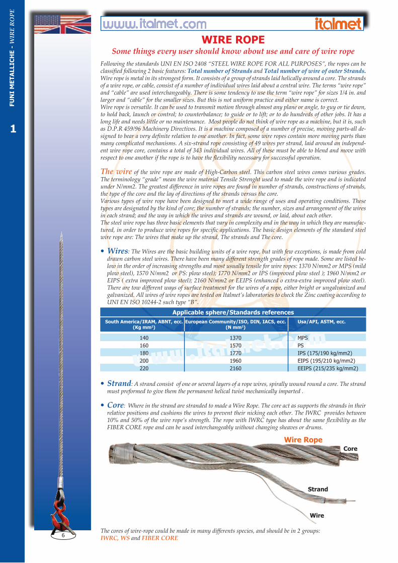
The wire of the wire rope are made of High-Carbon steel. This carbon steel wires comes various grades. The terminology “grade” mean the wire material Tensile Strenght used to made the wire rope and is indicated under N/mm2. The greatest difference in wire ropes are found in number of strands, constructions of strands, the type of the core and the lay of directions of the strands versus the core.Various types of wire rope have been designed to meet a wide range of uses and operating conditions. These types are designated by the kind of core; the number of strands; the number, sizes and arrangement of the wires in each strand; and the way in which the wires and strands are wound, or laid, about each other.The steel wire rope has three basic elements that vary in complexity and in the way in which they are manufac-tured, in order to produce wire ropes for specific applications. The basic design elements of the standard steel wire rope are: The wires that make up the strand, The strands and The core.
• Wires: The Wires are the basic building units of a wire rope, but with few exceptions, is made from cold drawn carbon steel wires. There have been many different strength grades of rope made. Some are listed be-low in the order of increasing strengths and most usually tensile for wire ropes: 1370 N/mm2 or MPS (mild plow steel), 1570 N/mm2 or PS: plow steel); 1770 N/mm2 or IPS (improved plow steel ); 1960 N/mm2 or EIPS ( extra improved plow steel); 2160 N/mm2 or EEIPS (enhanced o extra-extra improved plow steel). There are tow different ways of surface treatment for the wires of a rope, either bright or ungalvanized and galvanized. All wires of wire ropes are tested on Italmet’s laboratories to check the Zinc coating according to UNI EN ISO 10244-2 such type “B”.
• Strand: A strand consist of one or several layers of a rope wires, spirally wound round a core. The strand must preformed to give them the permanent helical twist mechanically imparted .
• Core: Where in the strand are stranded to made a Wire Rope. The core act as supports the strands in their relative positions and cushions the wires to prevent their nicking each other. The IWRC provides between 10% and 50% of the wire rope’s strength. The rope with IWRC type has about the same flexibility as the FIBER CORE rope and can be used interchangeably without changing sheaves or drums.
The cores of wire-rope could be made in many differents species, and should be in 2 groups:IWRC, WS and FIBER CORE
op ng y ging
www.italmet.com
Applicable sphere/Standards references
South America/IRAM, ABNT, ecc. European Community/ISO, DIN, IACS, ecc. Usa/API, ASTM, ecc. (Kg mm2) (N mm2)
140 1370 MPS
160 1570 PS
180 1770 IPS (175/190 kg/mm2)
200 1960 EIPS (195/210 kg/mm2)
220 2160 EEIPS (215/235 kg/mm2)
Wire RopeCore
Strand
Wire
FU
NI
ME
TA
LLIC
HE
- W
IRE
RO
PE
1

7
FUNI METALLICHEQualche nozione indispensabile che gli operatori devono conoscere
Secondo la norma UNI EN ISO 2408 “FUNI METALLICHE PER IMPIEGHI GENERALI” le funi si possono classificare sia per Numero di trefoli sia per la Quantità di fili esterni per trefolo. La fune Metallica è composta da materiali in una espressione di massima robustezza. Consiste in un gruppo di trefoli avvolti in senso elicoidale i quali a sua volta sono formati da un numero di fili indivi-duali avvolti attorno ad una anima. La fune metallica è molto versatile per cui si presta a diversi im-pieghi, sollevare, legare, controbilanciare, trainare, ecc. Bisogna considerare la Fune Metallica come “macchina”, come espresso nel D.P.R. 459/96 Direttiva Macchine, in quanto composta da precisi e complicati componenti in grado di trasmettere movimento con conseguente relazione tra loro.
La Fune è il risultato del procedimento di “trafilatura” dei singoli trefoli intorno ad una anima cen-trale, tessile o metallica che sia. Le Funi Metalliche sono trafilate con fili di acciaio ad elevata quantità di carbonio. A seconda della resistenza specifica dell’acciaio impiegato per la costruzione di una fune le viene assegnato il “grado” di resistenza. Questo termine viene usato per indicare la resistenza alla rottura dei fili elementari ed è espresso in N/mm2. Le funi possono variare per diametro, per numero e caratteristiche dei trefoli, per tipologia di costruzione o configurazione dei trefoli, per diametro del filo elementare, per finitura, per senso di avvolgimento e per tipologia dell’anima centrale.La fune metallica è composta essenzialmente da 3 elementi: Filo, Trefolo ed Anima.
• Filo: Il filo è l’elemento costitutivo essenziale della fune, può essere di diverse resistenze e si possono raggruppare in 5 classi di maggiore interesse: 1370 N/mm2 o MPS (mild plow steel), 1570 N/mm2 o PS:( plow steel); 1770 N/mm2 o IPS (improved plow steel ); 1960 N/mm2 o EIPS (extra improved plow steel); 2160 N/mm2 o EEIPS (enhanced o extra-extra improved plow steel).
Il filo può restare grezzo oppure sottoposto al processo di zincatura. Con il processo di zincatura si ottiene una sorta di protezione agli agenti atmosferici e corrosivi ai quali la fune può essere sotto-posta durante la vita lavorativa.Tutte le funi zincate illustrate in questo catalogo sono di zincatura tipo “B”. Inoltre queste funi sono sottoposte a verifiche del rivestimento della massa dello zinco nei nostri laboratori interni con il metodo volumetrico gassoso, accordo alla norma UNI EN ISO 10244-2
• Trefolo: E’ l’insieme di fili disposti in senso elicoidale intorno ad una anima. Questi possono essere sottoposti al procedimento di “Preformazione” per assicurare e garantire la compattezza al taglio della fune.
• Anima: E’ il corpo intorno al quale i trefoli subiscono il processo di trafilatura per dare origine alla “FUNE”. La funzione principale dell’anima è dare supporto ai singoli trefoli. Grazie ad esso la fune mantiene la sua forma durante l’impiego. L’Anima rappresenta tra il 10 e 50% della resistenza della fune. Le Funi con l’Anima metallica hanno le stesse caratteristiche di flessibilità rispetto alle Funi con Anima tessile, potendo così essere impiegate senza dover modificare l’apparecchiatura di lavoro.
La natura di questi corpi denominati “anima” possono essere di diversa specie, e si possono sud-dividere in due macro gruppi:
Anima Metallica e Anima Tessile
lavoro.
FuneAnima
Trefolo
Filo
www.italmet.com
Ambito d’applicazione/Ente certificatore
America del Sud/IRAM, ABNT, ecc. Comunità Europea/ISO, DIN, IACS, ecc. Usa/API, ASTM, ecc. (Kg mm2) (N mm2)
140 1370 MPS
160 1570 PS
180 1770 IPS (175/190 kg/mm2)
200 1960 EIPS (195/210 kg/mm2)
220 2160 EEIPS (215/235 kg/mm2)
FU
NI
ME
TA
LLIC
HE
- W
IRE
RO
PE
1

8
• IWRC and WS or WSC: Wire cores are made in two different forms. The one used most exten-sively is a wire rope of suitable size to serve as a core. Ropes with a steel core can work at temperatures up to 250°.
• It is called as independent wire rope core (IWRC) which is actually a rope in itself.
• The other type of wire core is a wire strand structure (WSC or SC). This consists of a multiple-wire strand, and may be the same construction as the main rope strands.
• Fiber Core “FC”: The core are made in Manila or Sisal fiber, Plastic, Polypropy-lene, Asbestos, Cot-ton is the type of core often used when loads are not too great. It supports strands in their relative positions and cushions the wires to prevent their nicking each other. Polypropylene cores, made up of a multiplicity of synthetic filaments extruded from a petrochemical resin. These are similar in physical construction to fiber cores.
Plastic impregnated fibre cores are sisal fiber cores impregnated with polyvinyl chloride (PVC). Fiber cores look like an ordinary hemp fiber rope. But in construction and lubrication they will differ somewhat.
Because of its wearing qualities and resiliency this core was for years the most popular center. But wire cores offer less stretch, have better resistance to heavy crushing loads and are not affected by heat. Ropes with a steel core could be with a plastic covered steel core PVC extruded to a specific thickness around the core, keep out water and abrasive elements, prevent internal wire breaks and more. Wire rope with FC cores should not be used at temperatures of more than 100 °.
Strand Wire Arrangement Most of the different wire arrangements used in the strands of the wire rope can be classified into 3 general types: Seale, Warrington and Filler. Wire inner and outer layer positioning and diameter are basis to assign the right strand wire arrangement.
• Seale: They have the same number of wire on both layers.The wires of the outer layer are ticker than those of the inner layer and each layer wires have the same diameter. That is the reason why a rope in Seale construction has a relatively low resistance to fatigue and a relatively high resist-ance to wear and deterioration.
• Warrington: type differs from the others in that: the outside layer is composed of twice numbers of wires alternately large and small and the inner layer consist of wires of the same diameter. A War-rington construction of rope therefore can be easily identified by this characteristic.
IWRC - WS Fiber Core
FU
NI
ME
TA
LLIC
HE
- W
IRE
RO
PE
1

9
• Anima Metallica - ”AM”: Composta di materiale metallico. Generalmente designata nel mercato nazionale in un solo macrogruppo con la nomenclatura “AM” e si intende anima metallica in genere, mentre per il mercato internazionale si ha la suddivisione a sua volta in due gruppi: “IWRC” e “WSC o SC”. Funi con anima Metallica possono essere impiegate in lavori con temperatura fino a 250°C.
• IWRC - Indipendent Wire Rope Core: In questo caso l’anima metallica è composta da una vera e propria fune.
• WSC o SC - Wire Strand Core Structure o Strand Core: In questo caso l’anima metallica è composta un singolo trefolo, richiamando la maggior parte dei casi la stessa costruzione dei trefoli esterni o principali.
• Anima Tessile - ”AT”: Corpo composto da fibre naturale o fibra sintetica (Manila o Sisal Fibre, Plastica, Polypropy-lene, Asbestos, Cotone). Supporta i trefoli nelle loro posizioni ed am-mortizza e previene lo schiacciamento dei singoli fili tra loro. La designazione per questa tipologia è “AT”.
L’anima a sua volta può essere rivestita di materiale plastico (PVC) ottenendo la riduzione della frizione tra i componenti della corona interna e quelli della corona esterna riducendo così i con-sumi e la possibilità della deformazione geometrica dei singoli componenti, inoltre prolunga la vita lavorativa della fune laddove il suo impiego sia in ambienti aggressivi (es. porti, piattaforme off-shore, navi, ecc.). Le funi con anima tessile NON devono essere impiegate in lavori dove la temperatura supera i 100°C.
Caratteristica di Configurazione dei TrefoliLa classificazione delle funi è data dalla quantità di fili esterni per trefolo e quindi dalla configurazione dei singoli fili nei trefoli e si possono riassumere in tre gruppi: SEALE, WARRINGTON e FILLER. Le caratteristiche fondamentali per la loro assegnazione sono date dal diametro dei fili della corona interna, dal diametro dei fili della corona esterna ed anche dal loro stesso posizionamento. Carat-teristiche come la resistenza alla Fatica o allo Sfregamento sono dettate esclusivamente dalla con-figurazione dei Trefoli. In termini generali, una fune metallica caratterizzata da una bassa quantità di fili per trefolo, (di conseguenza fili di diametro maggiore) sarà una fune maggiormente resistente allo sfregamento e meno alla fatica. Esempio: una fune con la formazione 6x19 è indicata per l’uso a sfregamento, mentre una fune con formazione 6x36 è indicata per la resistenza alla fatica. Questo rapporto si modifica con l’aumentare del diametro della fune dove si userà un maggior numero di fili per aumentare la resistenza alla fatica e sufficientemente grossi per garantire un ottimo impiego contro lo sfregamento.
• Seale: La caratteristica fondamentale di que-sta formazione è data dalla medesima quantità di fili nella corona esterna e la corona interna. Il diametro dei fili della corona esterna è mag-giore al diametro dei fili interni. Questa carat-teristica di costruzione/configurazione rende la fune estremamente resistente allo sfregamento ed abrasione, riducendo così la flessibilità e di conseguenza minor resistenza alla fatica.
FU
NI
ME
TA
LLIC
HE
- W
IRE
RO
PE
Anima Metallica Anima Tessile
1

10
• Filler: On the filler type the outside layer’s wires are uniform in size. The outer layer have twice number of wire as than of the inner layers. The wires of the inside layers of Filler arrangement are made up of a combination of main wires each of the same size, and smaller filler wires each of the same size, nested between the main wires. The outside layer of wires, therefore, is supported partly by the main in-side wires and partly by the filler wires.
In the 216 wires class, because of the greater number of wires used, combinations of the Filler Wire, Seale and Warrington types are used. The most popular combinations is Warrington-Seale given the best features of each strand wire arrangement more flexibility and more resistant to abrasion and pressure.
Rope Diameter and MeasurementThe rope diameter is the diameter of the circle drawn round the cross sections of the rope, is designed in mil-limeters (UNI EN ISO 4309). When put into service the wire rope diameter slightly decreases when first loaded. A further reduction in wire rope diameter indicates wear, abrasion, or core deterioration. Please check the allowable rope oversize tolerance as per UNI rules.
Table UNI EN ISO 2408
www.italmet.com
WRONG RIGHT
FU
NI
ME
TA
LLIC
HE
- W
IRE
RO
PE
Figure 1
1
Tolerance Rope Diameter % Rope Diameter mm I W R C F C
2 and 3 +7 -1 -
4 and 5 +6 -1 +8 -1
6 and 7 +5 -1 +7 -1
8 and up +4 -1 +6 -1

11
• Warrington: Questa formazione è caratte-rizzata dall’alternarsi di fili di due diametri diversi nella corona esterna, mentre i fili che compongo-no la corona interna sono di identico diametro fra loro. Questo tipo di costruzione/configurazione eredita gli stessi vantaggi della costruzione Sea-le migliorandone la flessibilità dovuta al maggior numero di fili nella corona esterna.
• Filler: Come nella costruzione SEALE, la co-rona esterna presenta lo stesso numero di fili elementari della corona interna. La caratteri-stica principale nella configurazione FILLER è data dalla composizione della corona interna risultato di una combinazione di fili dello stesso ed identico diametro al diametro dei fili della corona esterna e dal posizionamento di fili di diametro inferiore tra i fili principali. La doppia funzione esercitata dai fili di diametro inferiore è di supporto ai fili della corona esterna e di riempimento per i fili della corona interna.
E’ possibile avere più combinazioni di composizioni in una singola fune. Nel caso delle funi di classe 216 fili, a causa della alta quantità di fili usati, si possono trovare configurazioni come: Filler-Seale; Warrington-Seale; Seale-Filler, ecc. La combinazione più comune è la Warrington-Seale che prende le caratteristiche migliori di entrambe le configurazioni, ovvero fili di piccolo diametro nella corona interna apportando flessibilità alla fune e fili di grosso diametro nella corona esterna apportando maggiore resistenza allo sfregamento.
Diametro e Misurazione della FuneIl diametro nominale della fune è la misura della circonferenza della sezione che circoscrive la fune in ciascun momento della sua vita (UNI EN ISO 4309), ed è espressa in millimetri. La misurazione delle fune deve essere fatta come illustrato (figura 1), ed in due punti in una distanza di almeno 1 mt., applicandole una forza pari al 10% del carico di rottura, ottenendo così il DIAMETRO EFFETTIVO della fune. Come espresso dalla Norma UNI EN ISO 2408 ci sono delle tolleranze ammesse.
Tabella UNI EN ISO 2408
www.italmet.com
Tolleranza sul diametro nominale % Diametro nominale Funi con trefoli Funi con trefoli mm interamente di acciaio ad anima tessile
2 e 3 +7 -1 -
4 e 5 +6 -1 +8 -1
6 e 7 +5 -1 +7 -1
8 e più +4 -1 +6 -1
MISURAZIONE SBAGLIATA MISURAZIONE CORRETTA
Figura 1
FU
NI
ME
TA
LLIC
HE
- W
IRE
RO
PE
1

12
Wire Rope Lays Wire ropes have two types of lay. Lay means the direction in which the wires and strands are twisted around the rope. Right or left are used to refer to the lay of the strands
• Regular lay, as opposed to lang lay, denotes the direction of wire twist in the strands. In regular lay rope the wires in each strand lie in the “opposite” direction from the strands. “sZ” or “zS”.
• In Lang lay rope the wires in each strand lie in the “same” direction as the strands. “zZ” or “sS”.
Right regular lay is generally understood to be intended, unless other lay is specified. Exceptions occur in the case of certain types of well-drilling equipment. In some rope applications, direction of lay is important to proper performance of the job. In operating a clam-shell crane without a tag line to prevent rotation of the bucket--holding and closing lines are frequently opposite in direction of lay.
Wire Rope Lays Directions on the DrumsThe Drums is an important element of a Hoisting systems. Distinguishing between smooth or grooved drums and single or multiple layers. Most machines on which wire rope is used are designed for right regular lay rope.In some applications it may be advisable to select the rope lay direction according to the most frequently used drums layers. Be sure to use the correct rope lay direction for the drum and this applied to smooth drums as well as to grooved drums. If the first rope layer is used as a ‘guide layer’ only, it is advisable to select the rope lay direction according to the second layer. Is very important rolling up the rope close layers together on the first layer without overlapping or cross-over the other layers to not crushing the rope.
Single Layer Drums:• The rope lay directions has to be choose in opposite directions of the winding drums directions.
Multiple Layer Drums: • Following the rules to choose the right rope lay directions. See the drawing as above; • The first layers must be installed under tension; • Should be use Wedge. This provide to help to climb the next layers on the drums.
RHOL or sZRighthandordinary lay
LHOL or zSLefthandordinary lay
RHLLor zZRighthandlang lay
LHLLor sSLefthandlang lay
Underwind from right to left:Use Right Hand Rope
Underwind from left to right:Use Left Hand Rope
Overwind from left to right:Use Right Hand Rope
Overwind from right to left:Use Left Hand Rope
Right Hand Grooved:Use Left Hand Rope
Right Hand Grooved:Use Left Hand Rope
Left Hand Grooved:Use Right Hand Rope
Left Hand Grooved:
Use Right Hand Rope
Left Hand Grooved:Use Right Hand Rope
Right Hand Grooved:Use Left
Hand Rope
For RopeLeft Lay
For RopeRegular Lay
For RopeLeft Lay
For Rope Regular Lay
RightHandRope Left
HandRope
FU
NI
ME
TA
LLIC
HE
- W
IRE
RO
PE
1

13
Senso di AvvolgimentoE’ il senso di avvolgimento con il quale il filo ed il trefolo sono stati trafilati rispetto alla fune. Possono essere Crociato o Regolare oppure Parallelo. Il simbolo che identifica il senso di avvolgimento è formato da due lettere una maiuscola ed una minuscola: la lettera maiuscola evidenzia il senso di avvolgimento del trefolo mentre la lettera minuscola evidenzia il senso di avvolgimento del filo all’interno del trefolo.
• Crociato o Regolare: Denota il senso di avvolgimento “opposto” del filo sul trefolo. Può essere di senso destrorso “sZ” oppure sinistrorso “zS”.
• Parallelo: Denota il senso di Avvolgimento del filo nella “stessa” direzione sul trefolo. Può essere di senso parallelo destrorso “zZ” oppure parallelo sinistrorso “sS”.
Il senso di avvolgimento della fune, quando non diversamente espresso, si intende con crociato de-stro “sZ”. Il senso di avvolgimento Parallelo comporta molteplici benefici sia per la macchina sia per la stessa vita lavorativa della fune. Questo beneficio è esponenziale nelle funi speciali oppure nelle Antigiro.
Senso di Avvolgimento sul Tamburo E’ molto importante sapere se il tamburo dove si intende impiegare la fune si tratta di Tamburo Liscio oppure Tamburo scanalato a singola o multiple spire.La maggior parte delle attrezzature è studiata per alloggiare fune con avvolgimento destrorso. La verifica fondamentale da fare è assicurarsi dell’esistenza di un punto di aggancio o punto morto se si tratta di tamburo liscio. In caso di impiego di fune con avvolgimento sbagliato rispetto al senso di avvolgimento del tamburo il primo strato di fune tenderà ad allontanarsi dal punto di aggancio o punto morto provocando così spazi vuoti tra le spire della fune, avendo come conseguenza lo schiacciamento e la deformazione della fune.
Con Tamburo a singola spira di fune:• Fune con avvolgimento OPPOSTO al senso di avvolgimento del tamburo.
Con Tamburo a Multiple spira di fune si deve scegliere fune:• Fune con avvolgimento in accordo ai regolamenti. Vedi immagine sopra illustrata.• Le prime spire di fune dovranno essere avvolte in tensione.• L’uso di cunei o spessori possono aiutare il giusto avvolgimento della fune sul tamburo.
sZCrociatodestro
zSCrociatosinistro
zZParallelodestro
sSParallelosinistro
Avvolgimento inferioreda destra a sinistra:
utilizzare Funi destrorse
Avvolgimento inferioreda sinistra a destra:
utilizzare Funi sinistrorse
Avvolgimento superioreda sinistra a destra:
utilizzare Funi destrorse
Avvolgimento superioreda destra a sinistra:
utilizzare Funi sinistrorse
Scanalatoa destra:utilizzareFunisinistrorse
Scanalato a destra:utilizzare Funi sinistrorse
Scanalato a sinistra:utilizzare Funi destrorse
Scanalatoa sinistra:
utilizzareFuni
destrorse
Scanalatoa sinistra:utilizzareFunidestrorse
Scanalatoa destra:
utilizzareFuni
sinistrorse
Fune conavvolgiturasinistrorsa
Fune conavvolgituradestrorsa
Fune conavvolgiturasinistrorsa
Fune conavvolgituradestrorsa
Funedestrorsa
Fune sinistrorsa
FU
NI
ME
TA
LLIC
HE
- W
IRE
RO
PE
1

14
Diameter of Shaves and WinchesThe performance of all wire rope depends on the good condition and sufficient dimensions of sheaves and drums.Too small sheaves and drums will reduce the service life of a rope. This is more a question of ‘perform-ance’ rather than ‘safety’. The following table is based upon recommendations by the Wire Rope Technical Board:
Fleet AnglesMaximum rope fleet angle for general purpose Standard ropes should not exceed 4°. For non-rotating or rota-tion resistant ropes types the fleet angles should not exceed 1.5° with ungrooved drums and 2° for grooved drums.
Minimum Breaking Load MBLIs the minimum load at which the rope may fail or no longer support when reached breaking the whole rope (Breaking Load Test). It is in Kilonewton (kN). Refer the equations as listed below d2 x Qb x K x1 Fmin = 1000where Fmin is the MBL, d2 is square of the rope diameter, Qb is the tensile grade, K is the breaking strength constant. (The K value for standard rope are shown on UNI EN ISO 2408 standard and for Special ropes), see page 23.
Actual Breaking Load ABLIs the value determined by breaking the whole rope.
Calculated Breaking LoadIs the product of the metallic cross sections and the nominal strength of the wires.
WLL- Work Load LimitIs the maximum load the rope is designed to support in safety conditions. The WLL should be multiplied by safety factor becoming final applications. The number determined is the MBL of the rope.
Safety FactorThis factor gives the ratio between the Minimum Breaking Load and the Working Load Limit. The safety factor are given specifically for each product range, standards and the rules of third parties, i.e. Lifting ropes between 5-6 times, for lifting slings is 5 times, for personnel lift between 12-22 times.
www.italmet.comConstructions Number of outer strands Suggested D/d Ratio
19x7 - 18x7 - 14 SRS 12/14 34
6x26 6 30
WS6x25 Filler - 6x31 WS 6 26
6x36 WS - 9F19V - 9F19N - 10F16V - 10S16V 6/9/10 23
8x25 - 8F7KV - 8F7KN - 8WSTKL 8 20
VDW505 - 17S24K - 17SRS 15/16/17 20
(D= Diameter bottom of the shaves or the grooves (mm) d= Nominal rope diameter(mm))
Deflete angleswith ungroove drum
Deflete angleswith groove drum
1,50°
2° or 4°
FU
NI
ME
TA
LLIC
HE
- W
IRE
RO
PE
1

15
Diametro Pulegge e TamburiLa durata della vita lavorativa della fune che lavora attraverso puleggia e/o tamburo dipende dalle ottime condizioni di questi e dal giusto rapporto dimensionale tra il diametro della fune ed il diametro della puleggia e/o tamburo. Puleggia e/o tamburo molto piccoli riducono la vita lavorativa della fune. Vedi la tabella sotto riportata per rapporto D/d dove D= rappresenta il diametro del Tamburo e/o Puleggia a fondo gola e d= il diametro nominale della fune.
Angolo di DeflessioneE’ la deviazione massima consentita ad una fune tra il tamburo e la prima puleggia di rinvio. Il valore ammesso per i tamburi lisci è di 1,5 gradi, mentre non deve superare i 2 gradi se si tratta di tamburo scanalato ed impiego di fune Speciale od Antigiro, mentre non deve superare i 4° se si tratta di fune Standard.
Carico di Rottura MinimoE’ il valore minimo garantito per un campione di fune da sottoporre a verifica (test di rottura), è espresso in kilonewton (kN) UNI EN ISO 2408. Per le norme antinfortunistiche questo è il valore di riferimento che determina la portata della fune. Si ottiene con la seguente formula d2 x Qb x K x1 Fmin = 1000dove Fmin è il carico di rottura minimo, d2 è il valore del quadrato del diametro della fune di rife-rimento, Qb è il valore della resistenza unitaria del filo elementare, K è il coefficiente empirico del carico di rottura per una data formazione di fune. Questi valori sono espressi nella UNI EN ISO 2408 per le funi Standard e per le funi Speciali o Antigiro. Vedi tabella analitica del prodotto.
Carico di Rottura EffettivoE’ il valore ottenuto dalla prova di rottura su campione di fune sottoposto a verifica su banco prova. Questo valore deve essere sempre superiore o uguale al valore Minimo Garantito UNI EN ISO 3171.
Carico di Rottura CalcolatoE’ il prodotto tra il valore della sezione metallica della fune ed il valore della resistenza dei fili ele-mentari. Questo valore è puramente teorico e NON deve essere preso in esame per determinare la portata della fune.
Carico Massimo di UtilizzazioneE’ designato con la nomenclatura CMU “Carico Massimo di Utilizzazione”, alla quale la fune può essere sottoposta in condizione di impiego in accordo alle norme antinfortunistiche vigenti. Il CMU è soggetto ad un coefficiente di sicurezza variabile secondo gli impieghi.
www.italmet.com Tipologia di Fune Num. trefoli esterni Rapporto D/d
19x7 - 18x7 - 14 SRS 12/14 34
6x26 6 30
WS6x25 Filler - 6x31 WS 6 26
6x36 WS - 9F19V - 9F19N - 10F16V - 10S16V 6/9/10 23
8x25 - 8F7KV - 8F7KN - 8WSTKL 8 20
VDW505 - 17S24K - 17SRS 15/16/17 20
[D= Diametro fondo gola Tamburo/Puleggia (mm) d= Diam nominale Fune (mm)]
Angolo di deflessioneper tamburo liscio
Angolo di deflessioneper tamburo scanalato
1,50°
2° o 4°
FU
NI
ME
TA
LLIC
HE
- W
IRE
RO
PE
1

16
Fill FactorThe ration of the metallic cross section of a rope to the total cross sections.
Preforming Most ropes are preformed. A permanent helical twist is mechanically imparted to each strand before assembly. This eliminates built-in stress in the finished rope, and results in a better performing and longer-lived rope. With few exceptions (some drilling cables, some elevator ropes) almost all wire rope today is made preformed.
Compacted Rope Is a plastically deformed process of the wires achieved trough an compacting tool suck drawing tool or swaged machines. After this process the strand diameter are reduced and the surface is made smooth (Figure 2). This process improve the contact conditions between the individual wires and the strand to strand. Many of our wire ropes are made with either DIE-DRAWN STRANDS or the entire rope is subjected to a compaction process ROPE SWAGING.
Here are the differences:
• DIE-DRAWN STRANDS This process is applied to the strands NOT to the rope. The ready made strands are forced through drawing
dies which compress and shape the individual wires to have a flat outer surface. The advantages are: • increased strength; • less wire interlocking on multiple layer drums; • less contact pressures onto sheaves and drum.
• ROPE SWAGING This process is applied after the rope has been manufactured and compresses individual surface wires as well
as closing strand gaps.This process is usually applied to wire rope which is made using the double parallel manufacturing method, or where the rope core is plastic coated.
The advantages are: • increased strength: transforming
the entire rope into a more ‘round’ shape;
• less wire interlocking on multiple drums;
• less contact pressure onto sheave and drums;
• embedding strands into plastic coat-ed cores;
• achieve tighter diameter tolerances; • reduces constructional rope stretch
to near zero.
Designations Rope The terminology used to wire rope classifications is a International alphanumeric code trough numbers and letters are identified the ropes featuring. For standards wire ropes the first number mean the number of strand, the second number mean the total wire per strand. The letters means the strand arrangement constructions and the type of the core. Examples for a standard rope 6x36ws+IWRC: 6 strands, 36 wires per strands, War-rington-Seale strand constructions, Independent Wire Rope Core. The code have more informations for High Performance wire ropes like total number of strand for each layer, if it is a plastic coated and if it is compacted. Example PYTHON 8F7K-V is 8 = outer strands, F = Filler strand arrangement, 7 = Inner strands, K = plastic coated, V = Swaging rope.
Compactedwires surfaces
Spherical wires surfaces
Figure 2
FU
NI
ME
TA
LLIC
HE
- W
IRE
RO
PE
1

17
Coefficiente di SicurezzaE’ il coefficiente di declassamento che determina la portata della fune in base al massimo sforzo con-sentito o carico di rottura. I coefficienti di sicurezza sono svariati e si applicano a seconda del rego-lamento dell’ente certificatore ed anche a seconda dell’applicazione della fune metallica. Per esempio per le funi di sollevamento il coefficiente varia da 5 a 6; per i tiranti in fune è 5; per sollevamento persone varia da 12 a 22, ecc. Questo significa che una fune per sollevamento che ha un C.R. di 100 kN, la sua portata o CMU sarà di 20 kN
Fill-FactorE’ il coefficiente di riempimento della fune metallica. Questo coefficiente determina la “quantità” di acciaio presente in una data sezione della fune. Misura il rapporto tra la sezione metallica della fune e l’area stessa circoscritta dal diametro della fune.
Preformazione della FuneLa maggior parte delle funi in commercio subiscono un processo di preformazione, ad eccezione di qualche tipologia di fune per trivellazione o per elevatori, ottenendo cosi la deformazione elicoidale permanente del trefolo. I vantaggi: • I trefoli non si scompongono nel caso di tagli della fune. Anche i fili mantengono la loro posizione
in caso di rottura della fune.• Ottimo rendimento a fatica della fune;• Buona versatilità nella lavorazione delle cime.
Compattazione della Fune o Fune CompattateE’ il processo di deformazione della sezione che subiscono sia i singoli fili che i trefoli prima della trafilatura passando attraverso macchinari che “martellano” i componenti fino modificare la loro geometria “sferica” in una sezione avente una parte “appiattita” (figura 2). Questo processo tende a diminuire in modo drastico gli interstizi tra i fili nonché tra i trefoli di conseguenza aumentando la sezione metallica della fune, ottenendo così un più elevato carico di rottura a parità di diametro, maggiore resistenza alla fatica, alla pressione dovuta alle pulegge o rinvii (schiacciamento) ed anche allo sfregamento, una maggiore superficie di contatto tra i fili rendendo più uniforme la ripartizione delle forze sui singoli fili.
Questo procedimento può essere fatto in due modi: Trefoli Compattati e a Trefoli Compattati Martellati.
• Trefoli Compattati o Strand Compacted. Questo procedimento si realizza sui singoli fili elementari prima o durante la trafilatura, sottopo-
nendo i singoli trefoli alla deformazione geometrica passando attraverso una serie di rulli ottenendo l’appiattimento di tutta la superficie dei fili esterni del trefolo.
I vantaggi: • Aumenta la resistenza della fune; • Diminuisce la pressione di contatto nelle gole delle pulegge.
• Compattato-Martellato o Swage Compacted. Questo procedimento, a differenza del primo, si realizza direttamente a fune terminata e consiste
nella compressione dell’intera fune riportando così la schiacciatura solo della parte più esterna di ogni singolo filo del trefolo.
Questo procedimento è particolar-mente presente per le funi speciali aventi l’anima centrale metallica pla-stificata.
I vantaggi: • Aumenta la resistenza della fune; • Diminuisce la pressione di contat-
to nelle gole delle pulegge; • Ottimo alloggio del trefolo nella
guaina di plastica dell’anima; • Riduce pari a zero lo stress dai co-
struzione della fune
Trefoli compattati Trefoli non compattati
Figura 2
FU
NI
ME
TA
LLIC
HE
- W
IRE
RO
PE
1

18
Characteristic Standard RopesThe main features of Standard Wire Rope is 6 strands constructions. The 8 strands wire ropes are consider between Standard wire rope and Special wire rope. The right classifications depending of the technical specifica-tions for every kind of 8 strands rope. Standards wire rope have 6 outer strands ( 6x7, 6x19, 6x36, etc ) except 8 outer strands such 8x19.
Flexible rope, sometimes referred to as standard hoisting rope, covers six-strand rope containing as few as nine, but not greater than 26 wires per strand, with these wires arranged in several different strand pat-terns. This is the most popular and widely used class of wire ropes. Ropes in this class are furnished on a regular or lang lay. Cores may be fiber, independent wire rope or strand. The different constructions in this classification which have the greater number of wires generally are the more flexible, while the ones containing fewer wires are more resistant to abrasion and pressure.
Extra flexible rope, includes those containing six strands, with the number of wires per strand varying from 27 to 49, although the group is designated 6x37. The group is also referred to as extra flexible hoisting rope. Here, again, the greater number of wires the greater the flexibility, and the less resistance to pres-sure and abrasion. Overhead crane ropes are an example of this type of service.
Special flexible hoisting rope is a stable smooth-running rope, especially suitable, because of its flexibility, for high speed operation with reverse bends. This 8x19 class has 8 strands, usually around a fiber core. Most of this rope is right lay, regular lay.
Characteristic High PerformanceWire Ropes - Non Rotating ropesWhen loaded, every wire rope will develop torque; that is it has the tendency to unlay itself unless both rope ends are secured against rotation and cause a lower sheave block to rotate and to spin the line parts together.The characteristic of these wire ropes are that the outer layer is twisted in the opposite direction of their inner layers. With one rope end allowed to spin freely these and regular 6- strand ropes will spin violently and unlay them-selves when loaded. They may also develop a significant drop in breaking strength and an even larger drop in their fatigue life characteristic.As already mentioned, to achieve any degree of resisting the tendency of a rope to spin and unlay under load all such rope types (other than 4-strand ones) are constructed with 2 or more layers of opposite twisted strands. 2-layer ropes have a larger tendency to rotate than 3-layer ones (e.g. class 34x7). The 2-layer spin-resistant or rotation resistant ropes satisfy only low to moderate rotational resistance de-mands. The 3-layer rope constructions (e.g. class 35x7) have many more outer strands which can much better distrib-ute the radial pressures onto the reverse lay inner strands.These ropes should be selected for larger mobile- and ALL tower cranes.
FU
NI
ME
TA
LLIC
HE
- W
IRE
RO
PE
1

19
Designazione e Nomenclatura della Fune Metallica La nomenclatura usata per la designazione delle funi è estremamente semplice ed è Internazional-mente riconosciuta. Trattasi di una sorta di codice o sigla di carattere alfanumerico utili ad identificare la tipologia dei componenti della fune quali il numero di trefoli esterni, numeri dei fili per trefolo. Nelle funi con anima metallica “WSC” o “SC” è usato un secondo gruppo che indica la quantità di fili (1X23). Inoltre, nella nomenclatura della fune, sono comprese una prima serie di lettera che identifi-ca la configurazione di costruzione dei trefoli ed una seconda serie di lettere per identificare la natura dell’anima centrale.Esempio: per una fune standard 6x36ws+AM, il primo numero indica il numero dei trefoli esterni ed il secondo numero indica il numero di fili per ogni trefolo, quindi è una fune composta da 6 trefoli con 36 fili per trefolo. WS “Warrintong-Seale” che identifica la configurazione di costruzione dei trefoli ed infine AM che identifica la natura dell’anima centrale. Questa nomenclatura è usata per tutta la famiglia delle funi Standard, mentre per le più moderne tipologie di costruzione come le Funi Speciale può essere usata una nomenclatura con delle notizie aggiuntive. Per esempio la nomenclatura della fune PYTHON 8F7KV esprime il concetto di essere composta da 8 Trefoli esterni, “F” configurazione di costruzione “FILLER”, 7 è il numero dei trefoli della corona interna, “K” significa che l’anima centrale metallica è plastificata, “V” significa che il processo di compattazione della fune è “martellato”.
Caratteristiche delle Funi Standard Le funi denominate “standard” hanno 6 trefoli esterni (es. 6x7, 6x19, 6x36), tranne nella 8x19 (al confine delle funi speciali) che presenta 8 trefoli esterni.Fune Flessibile: Comunemente conosciuta come Standard Hoisting rope, configurata con 6 trefoli
esterni e meno di 26 fili per trefolo (6x19). Rappresenta la più comune famiglia delle funi me-talliche usate. Può essere fornita con anima sia Tessile che Metallica. La caratteristica di questa famiglia di funi è Flessibilità ed ottima resistenza allo sfregamento ed alla pressione.
Fune Extra Flessibile: Anche questa famiglia è composta da funi che presentano 6 trefoli esterni, ma la quantità dei fili aumenta. I numero di fili per trefolo è compreso tra 27 e 49 (6x36, 6x41). Può essere fornita con anima sia Tessile che Metallica. La caratteristica di questa famiglia di funi è ottima flessibilità ed una più bassa resistenza allo sfregamento ed alla pressione.
Fune Speciale Extra Flessibile: E’ rappresentato dalle funi con 8 Trefoli esterni (8x25). Parti-colarmente indicata dovuta alla loro flessibilità, per impieghi con macchinari di alta velocità di operazione. Può essere fornita con anima Tessile ed anima Metallica.
Caratteristiche delle Funi Antigiro o AntitorsioneLa fune metallica tende a “srotolarsi” o a ruotare nel suo stesso asse quando è sottoposta alla pres-sione di un carico. Si denominano funi Antitorsione tutte quelle funi cha a seguito della loro partico-lare costruzione non trasmettono un momento giratorio sul proprio asse quando è sottoposta ad una pressione di carico non guidato in sospensione. Caratteristica di costruzione di una fune antitorsione è quella di avere 2 o più corone di trefoli trafilate con opposto senso di rotazione tra di loro limitando o annullando quasi il momento rotatorio proprio della fune. Fune con 2 corone di trefoli è tendenzialmente più propenso a richiamare il momento rotatorio della fune rispetto ad una fune con 3 corone di trefoli (es. 35x7). Fune con 3 corone di trefoli è indicata per tutte le tipologie di grù mobili e grù a torre.
Le funi Antigiro o Antitorsione a sua volta si possono suddividere in tre gruppi in base al grado di capacità della fune di annullare il suo momento giratorio: Antitorsione o Spin-Resistant; Antiro-tazione o Rotation Resistant; Antigiro o Non Rotating.Per questi guppi di funi le caratteristiche di costruzione sono identiche e comuni tra loro. La diffe-renziazione è nella quantità di trefoli esterni e fondamentalmente nella quantità di corone di trefoli delle fune.
FU
NI
ME
TA
LLIC
HE
- W
IRE
RO
PE
1
20
RIGHT
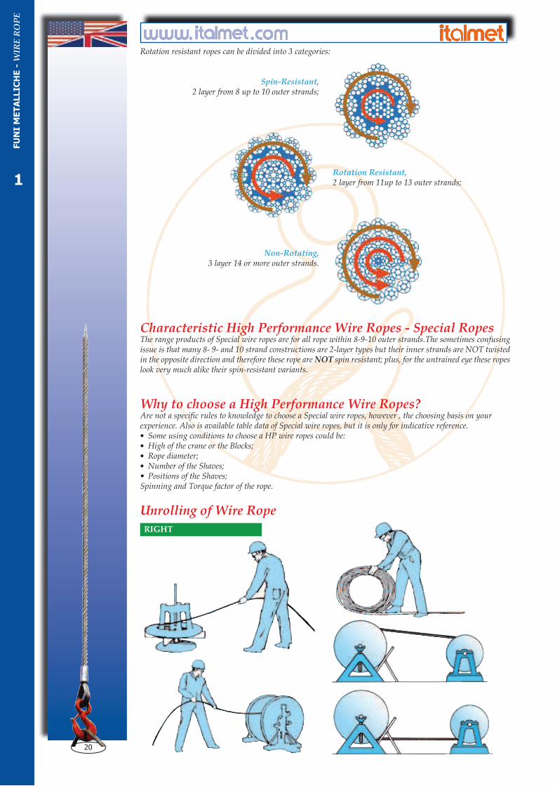
Rotation resistant ropes can be divided into 3 categories:
Spin-Resistant,2 layer from 8 up to 10 outer strands;
Rotation Resistant,2 layer from 11up to 13 outer strands;
Non-Rotating, 3 layer 14 or more outer strands.
Characteristic High Performance Wire Ropes - Special RopesThe range products of Special wire ropes are for all rope within 8-9-10 outer strands.The sometimes confusing issue is that many 8- 9- and 10 strand constructions are 2-layer types but their inner strands are NOT twisted in the opposite direction and therefore these rope are NOT spin resistant; plus, for the untrained eye these ropes look very much alike their spin-resistant variants.
Why to choose a High Performance Wire Ropes?Are not a specific rules to knowledge to choose a Special wire ropes, however , the choosing basis on your experience. Also is available table data of Special wire ropes, but it is only for indicative reference. • Some using conditions to choose a HP wire ropes could be: • High of the crane or the Blocks; • Rope diameter; • Number of the Shaves; • Positions of the Shaves; Spinning and Torque factor of the rope.
Unrolling of Wire Rope
FU
NI
ME
TA
LLIC
HE
- W
IRE
RO
PE
1

21
Antitorsione o Spin-Resistant:2 corone di trefoli da 8 a 10 trefoli esterni;
Antirotazione o Rotation Resistant:2 corone di trefoli da 11 a 13 trefoli esterni;
Antigiro o Non Rotating: 3 corone di trefoli da 14 o più trefoli esterni.
Caratteristiche delle Funi SpecialiSono comprese in questa famiglia tutte le funi composte da 8-9 e 10 trefoli esterni. In questa famiglia di funi i trefoli della corona esterna e la(e) corona(e) NON hanno lo stesso senso di rotazione. Questa categoria funi può trarre in inganno l’operatore inesperto visto le caratteristiche molto simili alle funi Antigiro, assegnandole in maniera impropria delle proprietà di antitorsione.
Scelta della fune Antigiro o SpecialeNon esiste un vera e propria regola che sancisca il “quando” usare una fune speciale o antigiro. In primo luogo conviene considerare esperienze precedenti di questo impiego. Se non ci fossero queste esperienze esistono delle tabelle e formule per questo uso, dettando valori di carattere puramente orientativo. Alcune condizioni che potrebbero determinare l’uso di queste funi sono:• Altezza del tiro;• Diametro della fune;• Diametro e disposizione delle pulegge;• Numero di rinvii;• Momento giratorio specifico della fune.Si consiglia di NON usare funi Antigiro quando il carico sia guidato.
Svolgimento della Fune
SISTEMA CORRETTOFU
NI
ME
TA
LLIC
HE
- W
IRE
RO
PE
1

22
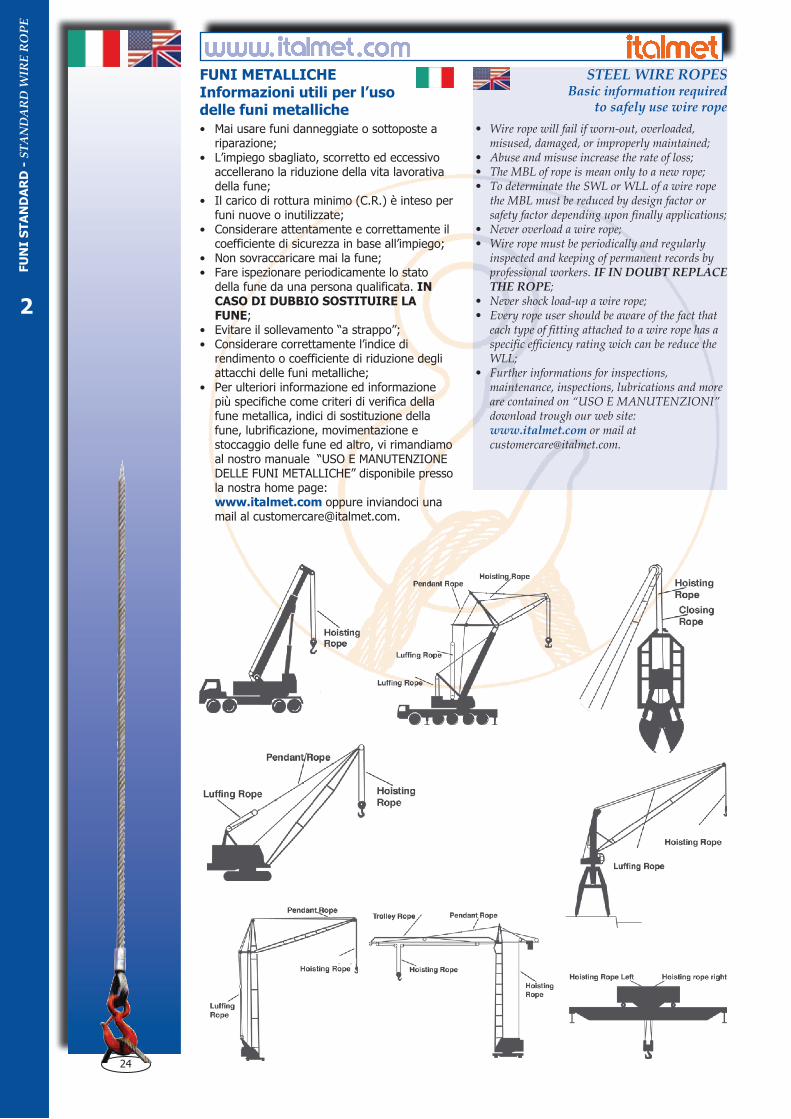
How to orderThe following is the minimum informations should be given on wire ropes puchase order or enquiry.• Total lenghts: EWL - Effective Working Lengts;• Surfaces of the wires will be furnished;• Diameter of rope;• Type of constructions of rope;• Type of core of the rope;• Nominal tensile strenght or MBL;• Strand arrangement constructions;• Type and direction of lay;• If will be furnished with end connections (Thimbles - Sockets - etc.)
This informations help us to follow you on use and know if we have the possibility to improve the working life of actually wire rope used or suggest the most favorable rope following your applications criterias.Further informations for inspections, maintenance, inspections, lubrications and more are contained on “USO E MANUTENZIONI” download trough our web site:
www.italmet.comor mail at
WRONG
FU
NI
ME
TA
LLIC
HE
- W
IRE
RO
PE
F
1
23
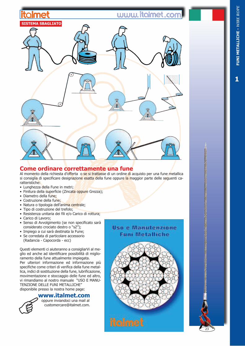
Come ordinare correttamente una funeAl momento della richiesta d’offerta o se si trattasse di un ordine di acquisto per una fune metallica si consiglia di specificare designazione esatta della fune oppure la maggior parte delle seguenti ca-ratteristiche:• Lunghezza della Fune in metri;• Finitura della superficie (Zincata oppure Grezza);• Diametro della fune;• Costruzione della fune; • Natura o tipologia dell’anima centrale;• Tipo di costruzione del trefolo;• Resistenza unitaria dei fili e/o Carico di rottura;• Carico di Lavoro;• Senso di Avvolgimento (se non specificato sarà
considerato crociato destro o “sZ”);• Impiego a cui sarà destinata la Fune;• Se corredata di particolare accessorio (Radancia - Capocorda - ecc)
Questi elementi ci aiuteranno a consigliarVi al me-glio ed anche ad identificare possibilità di miglio-ramento della fune attualmente impiegata.Per ulteriori informazione ed informazione più specifiche come criteri di verifica della fune metal-lica, indici di sostituzione della fune, lubrificazione, movimentazione e stoccaggio delle fune ed altro, vi rimandiamo al nostro manuale “USO E MANU-TENZIONE DELLE FUNI METALLICHE”disponibile presso la nostra home page:
www.italmet.comoppure inviandoci una mail al
SISTEMA SBAGLIATO
FU
NI
ME
TA
LLIC
HE
- W
IRE
RO
PE
F
1
24
FUNI METALLICHEInformazioni utili per l’usodelle funi metalliche
• Wire rope will fail if worn-out, overloaded, misused, damaged, or improperly maintained;
• Abuse and misuse increase the rate of loss;• The MBL of rope is mean only to a new rope;• To determinate the SWL or WLL of a wire rope
the MBL must be reduced by design factor or safety factor depending upon finally applications;
• Never overload a wire rope;• Wire rope must be periodically and regularly
inspected and keeping of permanent records by professional workers. IF IN DOUBT REPLACE THE ROPE;
• Never shock load-up a wire rope;• Every rope user should be aware of the fact that
each type of fitting attached to a wire rope has a specific efficiency rating wich can be reduce the WLL;
• Further informations for inspections, maintenance, inspections, lubrications and more are contained on “USO E MANUTENZIONI” download trough our web site:
www.italmet.com or mail at [email protected].
FU
NI
ST
AN
DA
RD
- S
TA
ND
AR
D W
IRE
RO
PE
• Mai usare funi danneggiate o sottoposte a riparazione;
• L’impiego sbagliato, scorretto ed eccessivo accellerano la riduzione della vita lavorativa della fune;
• Il carico di rottura minimo (C.R.) è inteso per funi nuove o inutilizzate;
• Considerare attentamente e correttamente il coefficiente di sicurezza in base all’impiego;
• Non sovraccaricare mai la fune;• Fare ispezionare periodicamente lo stato
della fune da una persona qualificata. IN CASO DI DUBBIO SOSTITUIRE LA FUNE;
• Evitare il sollevamento “a strappo”;• Considerare correttamente l’indice di
rendimento o coefficiente di riduzione degli attacchi delle funi metalliche;
• Per ulteriori informazione ed informazione più specifiche come criteri di verifica della fune metallica, indici di sostituzione della fune, lubrificazione, movimentazione e stoccaggio delle fune ed altro, vi rimandiamo al nostro manuale “USO E MANUTENZIONE DELLE FUNI METALLICHE” disponibile presso la nostra home page:
www.italmet.com oppure inviandoci una mail al [email protected].
STEEL WIRE ROPESBasic information required
to safely use wire rope
2