winder/unwind tension control - - get a free
TRANSCRIPT
MLP-Trim
5:1 MOTORVariable Speed Drive
560.0
(or)
COATING/HEATING/ LAMINATING/PRINTING
PROCESS
WINDER/UNWIND TENSION CONTROLYou may know them as winders, rewinds, recoilers or take-ups; likewise, you may know them as unwinds, uncoilers or pay-offs, but they are all the same subsection of web handling. Winders and unwinds are a critical portion of the process. The setup time required for loading and unloading need to be minimized, while maintaining safety. Also, accurate tension control at both ends of the process allows better process control throughout the machine.
Contrex (many still call us by our old name Fenner) has been a fixture in the web handling industry for decades. This industry has evolved over those years and Contrex has evolved right along with it. As manufacturers produce higher and higher quality products, at higher and higher speeds, the precise control that Contrex controllers give has become necessary in more and more manufacturing processes.
This white paper builds from the most basic control, to much more complicated systems. Many readers may want to skim the simple topics and jump to more advanced control methods. As always, please consult with Contrex regarding the best method for your particular machine. Contrex’s policy is to choose the least expensive (including set up costs) option that comfortably gets the job done. We have decades of experience across a broad range of industries. The Contrex products are a family of very precise speed controllers that give very accurate, easy-to-set process control. These products start out with a 0.01 percent accuracy in speed mode and true zero-error in follower mode. By allowing inexpensive 60 PPR ring kits or higher resolution surface speed encoders, they are flexible across a broad range of web applications.
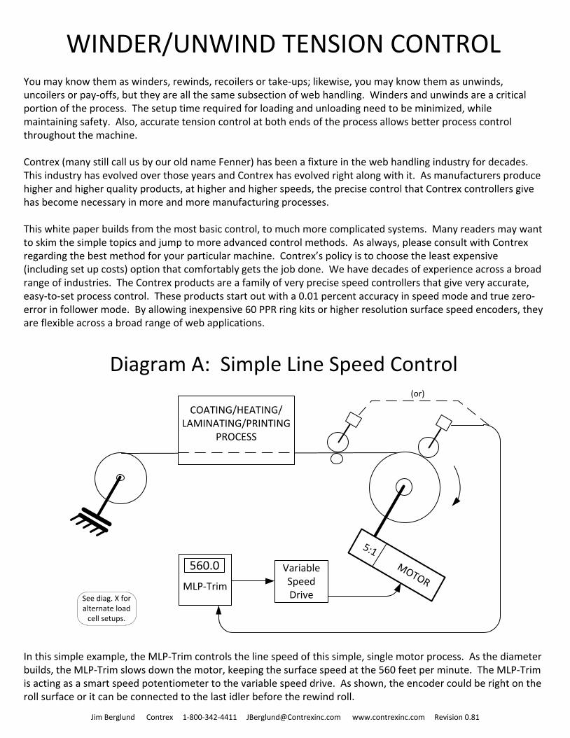
In this simple example, the MLP-Trim controls the line speed of this simple, single motor process. As the diameter builds, the MLP-Trim slows down the motor, keeping the surface speed at the 560 feet per minute. The MLP-Trim is acting as a smart speed potentiometer to the variable speed drive. As shown, the encoder could be right on the roll surface or it can be connected to the last idler before the rewind roll.
Jim Berglund Contrex 1-800-342-4411 [email protected] www.contrexinc.com Revision 0.81
Diagram A: Simple Line Speed Control
See diag. X for alternate load
cell setups.
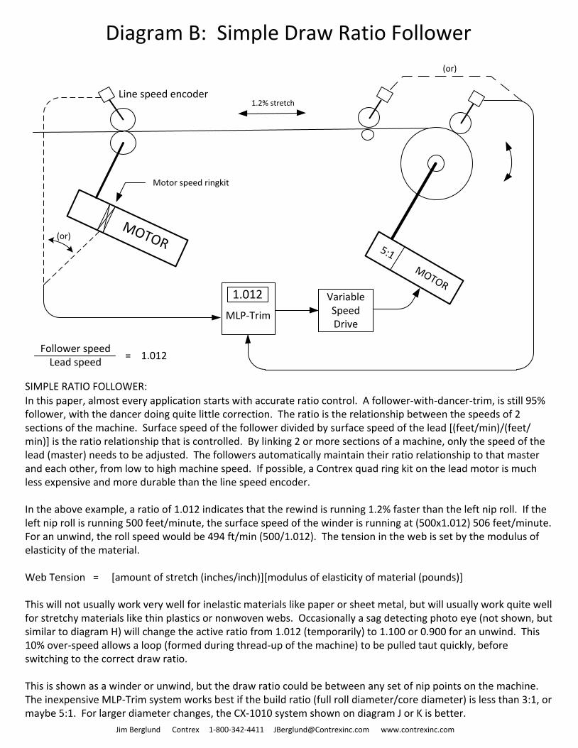
Diagram B: Simple Draw Ratio Follower
MOTOR
Motor speed ringkit
Line speed encoder
SIMPLE RATIO FOLLOWER:In this paper, almost every application starts with accurate ratio control. A follower-with-dancer-trim, is still 95% follower, with the dancer doing quite little correction. The ratio is the relationship between the speeds of 2 sections of the machine. Surface speed of the follower divided by surface speed of the lead [(feet/min)/(feet/min)] is the ratio relationship that is controlled. By linking 2 or more sections of a machine, only the speed of the lead (master) needs to be adjusted. The followers automatically maintain their ratio relationship to that master and each other, from low to high machine speed. If possible, a Contrex quad ring kit on the lead motor is much less expensive and more durable than the line speed encoder.
In the above example, a ratio of 1.012 indicates that the rewind is running 1.2% faster than the left nip roll. If the left nip roll is running 500 feet/minute, the surface speed of the winder is running at (500x1.012) 506 feet/minute. For an unwind, the roll speed would be 494 ft/min (500/1.012). The tension in the web is set by the modulus of elasticity of the material.
Web Tension = [amount of stretch (inches/inch)][modulus of elasticity of material (pounds)]
This will not usually work very well for inelastic materials like paper or sheet metal, but will usually work quite well for stretchy materials like thin plastics or nonwoven webs. Occasionally a sag detecting photo eye (not shown, but similar to diagram H) will change the active ratio from 1.012 (temporarily) to 1.100 or 0.900 for an unwind. This 10% over-speed allows a loop (formed during thread-up of the machine) to be pulled taut quickly, before switching to the correct draw ratio.
This is shown as a winder or unwind, but the draw ratio could be between any set of nip points on the machine. The inexpensive MLP-Trim system works best if the build ratio (full roll diameter/core diameter) is less than 3:1, or maybe 5:1. For larger diameter changes, the CX-1010 system shown on diagram J or K is better.
(or)
Follower speedLead speed
= 1.012
Jim Berglund Contrex 1-800-342-4411 [email protected] www.contrexinc.com
MLP-Trim
5:1 MOTORVariable Speed Drive
1.2% stretch
1.012
(or)
MLP-Trim
1.000
5:1 MOTOR
MOTOR
Variable Speed Drive
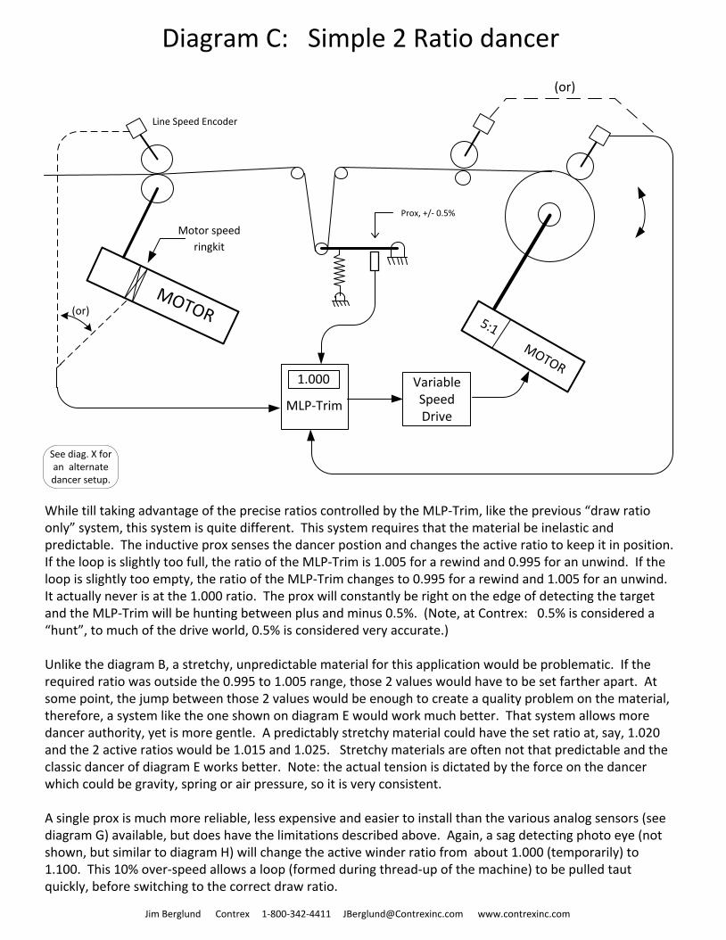
Diagram C: Simple 2 Ratio dancer
Line Speed Encoder
Prox, +/- 0.5%
Motor speed
ringkit
While till taking advantage of the precise ratios controlled by the MLP-Trim, like the previous “draw ratio only” system, this system is quite different. This system requires that the material be inelastic and predictable. The inductive prox senses the dancer postion and changes the active ratio to keep it in position. If the loop is slightly too full, the ratio of the MLP-Trim is 1.005 for a rewind and 0.995 for an unwind. If the loop is slightly too empty, the ratio of the MLP-Trim changes to 0.995 for a rewind and 1.005 for an unwind. It actually never is at the 1.000 ratio. The prox will constantly be right on the edge of detecting the target and the MLP-Trim will be hunting between plus and minus 0.5%. (Note, at Contrex: 0.5% is considered a “hunt”, to much of the drive world, 0.5% is considered very accurate.)
Unlike the diagram B, a stretchy, unpredictable material for this application would be problematic. If the required ratio was outside the 0.995 to 1.005 range, those 2 values would have to be set farther apart. At some point, the jump between those 2 values would be enough to create a quality problem on the material, therefore, a system like the one shown on diagram E would work much better. That system allows more dancer authority, yet is more gentle. A predictably stretchy material could have the set ratio at, say, 1.020 and the 2 active ratios would be 1.015 and 1.025. Stretchy materials are often not that predictable and the classic dancer of diagram E works better. Note: the actual tension is dictated by the force on the dancer which could be gravity, spring or air pressure, so it is very consistent.
A single prox is much more reliable, less expensive and easier to install than the various analog sensors (see diagram G) available, but does have the limitations described above. Again, a sag detecting photo eye (not shown, but similar to diagram H) will change the active winder ratio from about 1.000 (temporarily) to 1.100. This 10% over-speed allows a loop (formed during thread-up of the machine) to be pulled taut quickly, before switching to the correct draw ratio.
(or)
(or)
Jim Berglund Contrex 1-800-342-4411 [email protected] www.contrexinc.com
See diag. X for an alternate dancer setup.
MLP-Trim
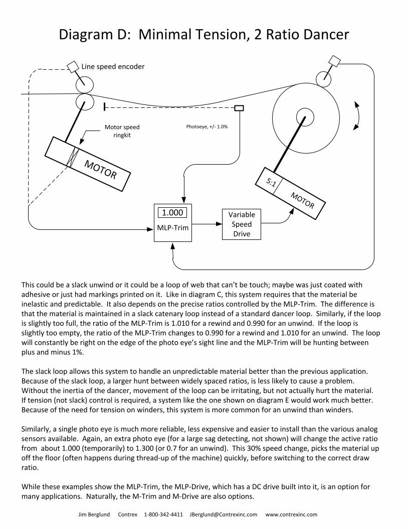
Diagram D: Minimal Tension, 2 Ratio Dancer
5:1 MOTOR
MOTOR
Motor speed ringkit
Line speed encoder
Variable Speed Drive
1.000
Photoeye, +/- 1.0%
This could be a slack unwind or it could be a loop of web that can’t be touch; maybe was just coated with adhesive or just had markings printed on it. Like in diagram C, this system requires that the material be inelastic and predictable. It also depends on the precise ratios controlled by the MLP-Trim. The difference is that the material is maintained in a slack catenary loop instead of a standard dancer loop. Similarly, if the loop is slightly too full, the ratio of the MLP-Trim is 1.010 for a rewind and 0.990 for an unwind. If the loop is slightly too empty, the ratio of the MLP-Trim changes to 0.990 for a rewind and 1.010 for an unwind. The loop will constantly be right on the edge of the photo eye’s sight line and the MLP-Trim will be hunting between plus and minus 1%.
The slack loop allows this system to handle an unpredictable material better than the previous application. Because of the slack loop, a larger hunt between widely spaced ratios, is less likely to cause a problem. Without the inertia of the dancer, movement of the loop can be irritating, but not actually hurt the material. If tension (not slack) control is required, a system like the one shown on diagram E would work much better. Because of the need for tension on winders, this system is more common for an unwind than winders.
Similarly, a single photo eye is much more reliable, less expensive and easier to install than the various analog sensors available. Again, an extra photo eye (for a large sag detecting, not shown) will change the active ratio from about 1.000 (temporarily) to 1.300 (or 0.7 for an unwind). This 30% speed change, picks the material up off the floor (often happens during thread-up of the machine) quickly, before switching to the correct draw ratio.
While these examples show the MLP-Trim, the MLP-Drive, which has a DC drive built into it, is an option for many applications. Naturally, the M-Trim and M-Drive are also options.
Jim Berglund Contrex 1-800-342-4411 [email protected] www.contrexinc.com
MLP-Trim
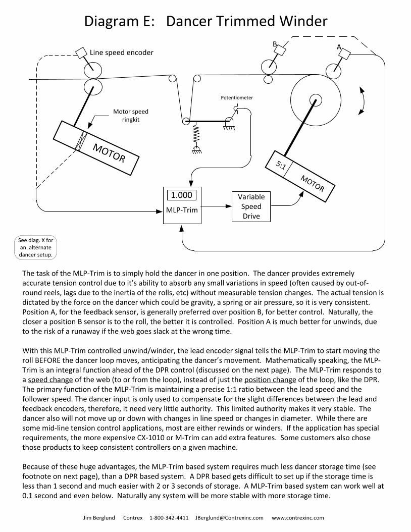
Diagram E: Dancer Trimmed Winder
5:1 MOTOR
MOTOR
Motor speed ringkit
Line speed encoder
Variable Speed Drive
1.000
Potentiometer
The task of the MLP-Trim is to simply hold the dancer in one position. The dancer provides extremely accurate tension control due to it’s ability to absorb any small variations in speed (often caused by out-of-round reels, lags due to the inertia of the rolls, etc) without measurable tension changes. The actual tension is dictated by the force on the dancer which could be gravity, a spring or air pressure, so it is very consistent. Position A, for the feedback sensor, is generally preferred over position B, for better control. Naturally, the closer a position B sensor is to the roll, the better it is controlled. Position A is much better for unwinds, due to the risk of a runaway if the web goes slack at the wrong time.
With this MLP-Trim controlled unwind/winder, the lead encoder signal tells the MLP-Trim to start moving the roll BEFORE the dancer loop moves, anticipating the dancer’s movement. Mathematically speaking, the MLP-Trim is an integral function ahead of the DPR control (discussed on the next page). The MLP-Trim responds to a speed change of the web (to or from the loop), instead of just the position change of the loop, like the DPR. The primary function of the MLP-Trim is maintaining a precise 1:1 ratio between the lead speed and the follower speed. The dancer input is only used to compensate for the slight differences between the lead and feedback encoders, therefore, it need very little authority. This limited authority makes it very stable. The dancer also will not move up or down with changes in line speed or changes in diameter. While there are some mid-line tension control applications, most are either rewinds or winders. If the application has special requirements, the more expensive CX-1010 or M-Trim can add extra features. Some customers also chose those products to keep consistent controllers on a given machine.
Because of these huge advantages, the MLP-Trim based system requires much less dancer storage time (see footnote on next page), than a DPR based system. A DPR based gets difficult to set up if the storage time is less than 1 second and much easier with 2 or 3 seconds of storage. A MLP-Trim based system can work well at 0.1 second and even below. Naturally any system will be more stable with more storage time.
Jim Berglund Contrex 1-800-342-4411 [email protected] www.contrexinc.com
B A
See diag. X for an alternate dancer setup.
Dancer Position
Regulator (DPR) Card
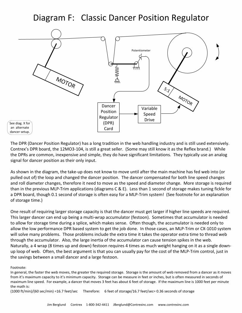
Diagram F: Classic Dancer Position Regulator
5:1 MOTOR
MOTOR
Variable Speed Drive
Potentiometer
The DPR (Dancer Position Regulator) has a long tradition in the web handling industry and is still used extensively. Contrex’s DPR board, the 12MO3-104, is still a great seller. (Some may still know it as the Reflex brand.) While the DPRs are common, inexpensive and simple, they do have significant limitations. They typically use an analog signal for dancer position as their only input.
As shown in the diagram, the take-up does not know to move until after the main machine has fed web into (or pulled out of) the loop and changed the dancer position. The dancer compensated for both line speed changes and roll diameter changes, therefore it need to move as the speed and diameter change. More storage is required than in the previous MLP-Trim applications (diagrams C & E). Less than 1 second of storage makes tuning fickle for a DPR board, though 0.1 second of storage is often easy for a MLP-Trim system! (See footnote for an explanation of storage time.)
One result of requiring larger storage capacity is that the dancer must get larger if higher line speeds are required. This larger dancer can end up being a multi-wrap accumulator (festoon). Sometimes that accumulator is needed to allow for storage time during a splice, which makes sense. Often though, the accumulator is needed only to allow the low performance DPR based system to get the job done. In those cases, an MLP-Trim or CX-1010 system will solve many problems. Those problems include the extra time it takes the operator extra time to thread web through the accumulator. Also, the large inertia of the accumulator can cause tension spikes in the web. Naturally, a 4 wrap (8 times up and down) festoon requires 4 times as much weight hanging on it as a single down-up loop of web. Often, the best argument is that you can usually pay for the cost of the MLP-Trim control, just in the savings between a small dancer and a large festoon.
Footnote:In general, the faster the web moves, the greater the required storage. Storage is the amount of web removed from a dancer as it moves from it’s maximum capacity to it’s minimum capacity. Storage can be measure in feet or inches, but is often measured in seconds of maximum line speed. For example, a dancer that moves 3 feet has about 6 feet of storage. If the maximum line is 1000 feet per minute the math is: (1000 ft/min)/(60 sec/min) =16.7 feet/sec Therefore: 6 feet of storage/16.7 feet/sec= 0.36 seconds of storage
Jim Berglund Contrex 1-800-342-4411 [email protected] www.contrexinc.com
See diag. X for an alternate dancer setup.
Jim Berglund Contrex 1-800-342-4411 [email protected] www.contrexinc.com
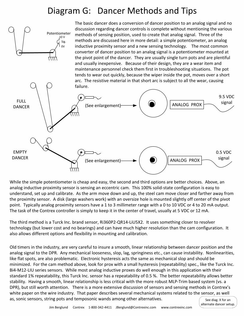
Diagram G: Dancer Methods and TipsThe basic dancer does a conversion of dancer position to an analog signal and no discussion regarding dancer controls is complete without mentioning the various methods of sensing position, used to create that analog signal. Three of the methods are discussed here in more detail: a simple potentiometer, an analog inductive proximity sensor and a new sensing technology. The most common converter of dancer position to an analog signal is a potentiometer mounted at the pivot point of the dancer. They are usually single turn pots and are plentiful and usually inexpensive. Because of their design, they are a wear item and maintenance personnel check them first in troubleshooting situations. The pot tends to wear out quickly, because the wiper inside the pot, moves over a short arc. The resistive material in that short arc is subject to all the wear, causing failure.
Potentiometer
ANALOG PROX(See enlargement)
(See enlargement)
9.5 VDC signalFULL
DANCER
EMPTY DANCER
While the simple potentiometer is cheap and easy, the second and third options are better choices. Above, an analog inductive proximity sensor is sensing an eccentric cam. This 100% solid-state configuration is easy to understand, set up and calibrate. As the arm move down and up, the steel cam move closer and farther away from the proximity sensor. A disk (large washers work) with an oversize hole is mounted slightly off center of the pivot point. Typically analog proximity sensors have a 1 to 3 millimeter range with a 0 to 10 VDC or 4 to 20 mA output. The task of the Contrex controller is simply to keep it in the center of travel, usually at 5 VDC or 12 mA.
The third method is a Turck Inc. brand sensor, Ri360P2-QR14-LiU5X2. It uses something closer to resolver technology (but lower cost and no bearings) and can have much higher resolution than the cam configuration. It also allows different options and flexibility in mounting and calibration.
Old timers in the industry, are very careful to insure a smooth, linear relationship between dancer position and the analog signal to the DPR. Any mechanical looseness, slop, lag, springiness etc., can cause instability. Nonlinearities, like flat spots, are also problematic. Electronic hysteresis acts the same as mechanical slop and should be minimized. For the cam method above, look for prox with a small hysteresis (repeatability) spec., like the Turck Inc. Bi4-M12-LIU series sensors. While most analog inductive proxes do well enough in this application with their standard 1% repeatability, this Turck Inc. sensor has a repeatability of 0.5 %. The better repeatability allows better stability. Having a smooth, linear relationship is less critical with the more robust MLP-Trim based system (vs. a DPR), but still worth attention. There is a more extensive discussion of sensors and sensing methods in Contrex’s white paper on the wire industry. That paper describes several mechanical systems related to the sensor, as well as, sonic sensors, string pots and temposonic wands among other alternatives.
ANALOG PROX
0.5 VDC signal
10 V
0V
Sig.
See diag. X for an alternate dancer setup.
MLP-Trim
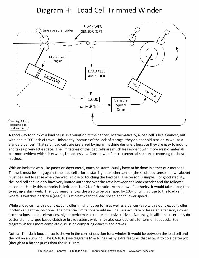
Diagram H: Load Cell Trimmed Winder
5:1 MOTOR
MOTOR
Motor speed ringkit
Line speed encoder
Variable Speed Drive
1.000
SLACK WEB SENSOR (OPT.)
LOAD CELLAMPLIFIER
A good way to think of a load cell is as a variation of the dancer. Mathematically, a load cell is like a dancer, but with about .003 inch of travel. Inherently, because of the lack of storage, they do not hold tension as well as a standard dancer. That said, load cells are preferred by many machine designers because they are easy to mount and take up very little space. The limitations of the load cells are much less evident with more elastic materials, but more evident with sticky webs, like adhesives. Consult with Contrex technical support in choosing the best method.
With an inelastic web, like paper or sheet metal, machine starts usually have to be done in either of 2 methods. The web must be snug against the load cell prior to starting or another sensor (the slack loop sensor shown above) must be used to sense when the web is close to touching the load cell. The reason is simple. For good stability, the load cell should only have very limited authority over the ratio between the lead encoder and the follower encoder. Usually this authority is limited to 1 or 2% of the ratio. At that low of authority, it would take a long time to eat up a slack web. The loop sensor allows the web to be over sped by 10%, until it is close to the load cell, where is switches back to a (near) 1:1 ratio between the lead speed and follower speed.
While a load cell (with a Contrex controller) might not perform as well as a dancer (also with a Contrex controller), it often can get the job done. The potential limitations would include: less accurate or less stable tension, slower accelerations and decelerations, higher performance (more expensive) drives. Naturally, it will almost certainly do better than a torque based clutch or brake system, which may also use load cells for tension feedback. See diagram W for a more complete discussion comparing dancers and brakes.
Notes: The slack loop sensor is shown in the correct position for a winder, it would be between the load cell and the roll on an unwind. The CX-1010 (see diagrams M & N) has many extra features that allow it to do a better job (though at a higher price) than the MLP-Trim.
Jim Berglund Contrex 1-800-342-4411 [email protected] www.contrexinc.com
See diag. X for alternate load
cell setups.
MLP-Trim
Diagram I: Minimal Tension, Sonic Trimmed Winder
5:1 MOTOR
MOTOR
Motor speed ringkit
Line speed encoder
Variable Speed Drive
1.000
ANALOG SIGNAL FROM SONIC SENSOR
SONIC SENSOR
“A”
SONIC SENSOR
“B”
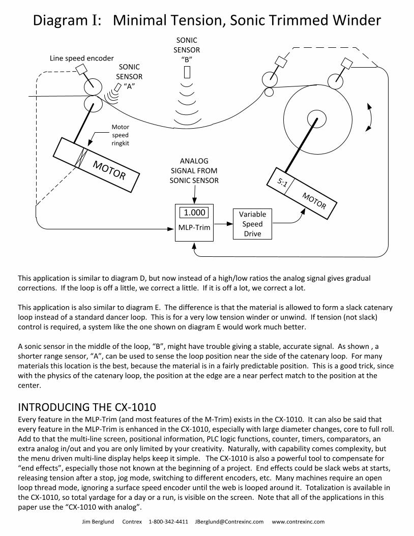
This application is similar to diagram D, but now instead of a high/low ratios the analog signal gives gradual corrections. If the loop is off a little, we correct a little. If it is off a lot, we correct a lot.
This application is also similar to diagram E. The difference is that the material is allowed to form a slack catenary loop instead of a standard dancer loop. This is for a very low tension winder or unwind. If tension (not slack) control is required, a system like the one shown on diagram E would work much better.
A sonic sensor in the middle of the loop, “B”, might have trouble giving a stable, accurate signal. As shown , a shorter range sensor, “A”, can be used to sense the loop position near the side of the catenary loop. For many materials this location is the best, because the material is in a fairly predictable position. This is a good trick, since with the physics of the catenary loop, the position at the edge are a near perfect match to the position at the center.
INTRODUCING THE CX-1010 Every feature in the MLP-Trim (and most features of the M-Trim) exists in the CX-1010. It can also be said that every feature in the MLP-Trim is enhanced in the CX-1010, especially with large diameter changes, core to full roll. Add to that the multi-line screen, positional information, PLC logic functions, counter, timers, comparators, an extra analog in/out and you are only limited by your creativity. Naturally, with capability comes complexity, but the menu driven multi-line display helps keep it simple. The CX-1010 is also a powerful tool to compensate for “end effects”, especially those not known at the beginning of a project. End effects could be slack webs at starts, releasing tension after a stop, jog mode, switching to different encoders, etc. Many machines require an open loop thread mode, ignoring a surface speed encoder until the web is looped around it. Totalization is available in the CX-1010, so total yardage for a day or a run, is visible on the screen. Note that all of the applications in this paper use the “CX-1010 with analog”.
Jim Berglund Contrex 1-800-342-4411 [email protected] www.contrexinc.com
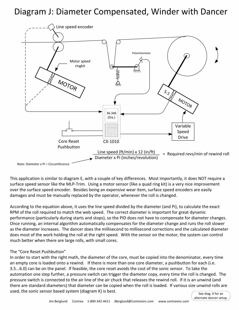
Diagram J: Diameter Compensated, Winder with Dancer
5:1 MOTOR
MOTOR
Motor speed ringkit
Line speed encoder
Variable Speed Drive
Potentiometer
36.346(Dia.)
Core ResetPushbutton
This application is similar to diagram E, with a couple of key differences. Most importantly, it does NOT require a surface speed sensor like the MLP-Trim. Using a motor sensor (like a quad ring kit) is a very nice improvement over the surface speed encoder. Besides being an expensive wear item, surface speed encoders are easily damages and must be manually replaced by the operator, whenever the roll is changed.
According to the equation above, it uses the line speed divided by the diameter (and Pi), to calculate the exact RPM of the roll required to match the web speed. The correct diameter is important for great dynamic performance (particularly during starts and stops), so the PID does not have to compensate for diameter changes. Once running, an internal algorithm automatically compensates for the diameter change and runs the roll slower as the diameter increases. The dancer does the millisecond to millisecond corrections and the calculated diameter does most of the work holding the roll at the right speed. With the sensor on the motor, the system can control much better when there are large rolls, with small cores.
The “Core Reset Pushbutton”In order to start with the right math, the diameter of the core, must be copied into the denominator, every time an empty core is loaded onto a rewind. If there is more than one core diameter, a pushbutton for each (i.e. 3.5...6.0) can be on the panel. If feasible, the core reset avoids the cost of the sonic sensor. To take the automation one step further, a pressure switch can trigger the diameter copy, every time the roll is changed. The pressure switch is connected to the air line of the air chuck that releases the rewind roll. If it is an unwind (and there are standard diameters) that diameter can be copied when the roll is loaded. If various size unwind rolls are used, the sonic sensor based system (diagram K) is best.
Jim Berglund Contrex 1-800-342-4411 [email protected] www.contrexinc.com
Line speed (ft/min) x 12 (in/ft)Diameter x Pi (inches/revolution)
= Required revs/min of rewind roll
Note: Diameter x Pi = Circumference
CX-1010
See diag. X for an alternate dancer setup.
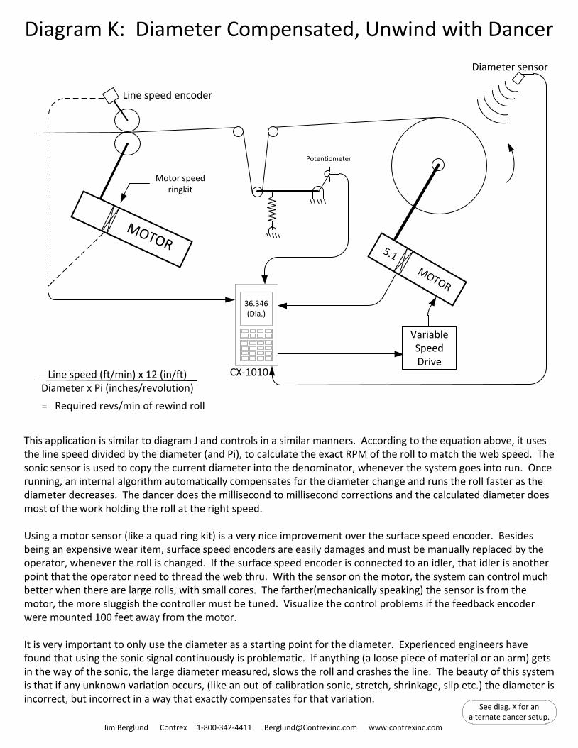
Diagram K: Diameter Compensated, Unwind with Dancer
5:1 MOTOR
MOTOR
Motor speed ringkit
Line speed encoder
Variable Speed Drive
Potentiometer
36.346(Dia.)
Diameter sensor
Jim Berglund Contrex 1-800-342-4411 [email protected] www.contrexinc.com
This application is similar to diagram J and controls in a similar manners. According to the equation above, it uses the line speed divided by the diameter (and Pi), to calculate the exact RPM of the roll to match the web speed. The sonic sensor is used to copy the current diameter into the denominator, whenever the system goes into run. Once running, an internal algorithm automatically compensates for the diameter change and runs the roll faster as the diameter decreases. The dancer does the millisecond to millisecond corrections and the calculated diameter does most of the work holding the roll at the right speed.
Using a motor sensor (like a quad ring kit) is a very nice improvement over the surface speed encoder. Besides being an expensive wear item, surface speed encoders are easily damages and must be manually replaced by the operator, whenever the roll is changed. If the surface speed encoder is connected to an idler, that idler is another point that the operator need to thread the web thru. With the sensor on the motor, the system can control much better when there are large rolls, with small cores. The farther(mechanically speaking) the sensor is from the motor, the more sluggish the controller must be tuned. Visualize the control problems if the feedback encoder were mounted 100 feet away from the motor.
It is very important to only use the diameter as a starting point for the diameter. Experienced engineers have found that using the sonic signal continuously is problematic. If anything (a loose piece of material or an arm) gets in the way of the sonic, the large diameter measured, slows the roll and crashes the line. The beauty of this system is that if any unknown variation occurs, (like an out-of-calibration sonic, stretch, shrinkage, slip etc.) the diameter is incorrect, but incorrect in a way that exactly compensates for that variation.
CX-1010Line speed (ft/min) x 12 (in/ft)Diameter x Pi (inches/revolution)
= Required revs/min of rewind roll
See diag. X for an alternate dancer setup.
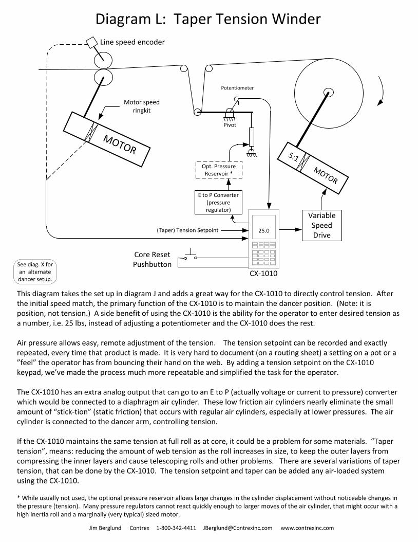
Diagram L: Taper Tension Winder
5:1 MOTOR
MOTOR
Motor speed ringkit
Line speed encoder
Variable Speed Drive
Potentiometer
25.0
Opt. Pressure Reservoir *
E to P Converter(pressure regulator)
(Taper) Tension Setpoint
Pivot
This diagram takes the set up in diagram J and adds a great way for the CX-1010 to directly control tension. After the initial speed match, the primary function of the CX-1010 is to maintain the dancer position. (Note: it is position, not tension.) A side benefit of using the CX-1010 is the ability for the operator to enter desired tension as a number, i.e. 25 lbs, instead of adjusting a potentiometer and the CX-1010 does the rest.
Air pressure allows easy, remote adjustment of the tension. The tension setpoint can be recorded and exactly repeated, every time that product is made. It is very hard to document (on a routing sheet) a setting on a pot or a ”feel” the operator has from bouncing their hand on the web. By adding a tension setpoint on the CX-1010 keypad, we’ve made the process much more repeatable and simplified the task for the operator.
The CX-1010 has an extra analog output that can go to an E to P (actually voltage or current to pressure) converter which would be connected to a diaphragm air cylinder. These low friction air cylinders nearly eliminate the small amount of “stick-tion” (static friction) that occurs with regular air cylinders, especially at lower pressures. The air cylinder is connected to the dancer arm, controlling tension.
If the CX-1010 maintains the same tension at full roll as at core, it could be a problem for some materials. “Taper tension”, means: reducing the amount of web tension as the roll increases in size, to keep the outer layers from compressing the inner layers and cause telescoping rolls and other problems. There are several variations of taper tension, that can be done by the CX-1010. The tension setpoint and taper can be added any air-loaded system using the CX-1010.
* While usually not used, the optional pressure reservoir allows large changes in the cylinder displacement without noticeable changes in the pressure (tension). Many pressure regulators cannot react quickly enough to larger moves of the air cylinder, that might occur with a high inertia roll and a marginally (very typical) sized motor.
Jim Berglund Contrex 1-800-342-4411 [email protected] www.contrexinc.com
CX-1010
Core ResetPushbuttonSee diag. X for
an alternate dancer setup.
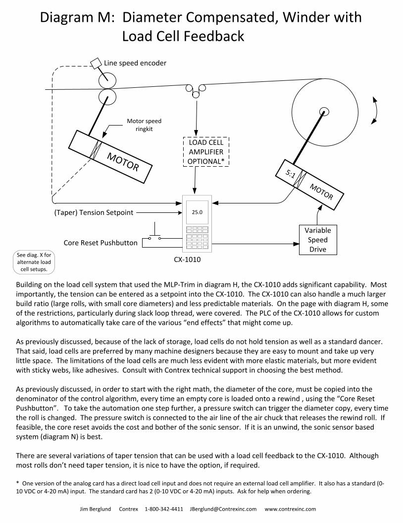
Diagram M: Diameter Compensated, Winder with Load Cell Feedback
5:1 MOTOR
MOTOR
Motor speed ringkit
Line speed encoder
Variable Speed Drive
25.0
Core Reset Pushbutton
LOAD CELLAMPLIFIEROPTIONAL*
(Taper) Tension Setpoint
Jim Berglund Contrex 1-800-342-4411 [email protected] www.contrexinc.com
Building on the load cell system that used the MLP-Trim in diagram H, the CX-1010 adds significant capability. Most importantly, the tension can be entered as a setpoint into the CX-1010. The CX-1010 can also handle a much larger build ratio (large rolls, with small core diameters) and less predictable materials. On the page with diagram H, some of the restrictions, particularly during slack loop thread, were covered. The PLC of the CX-1010 allows for custom algorithms to automatically take care of the various “end effects” that might come up.
As previously discussed, because of the lack of storage, load cells do not hold tension as well as a standard dancer. That said, load cells are preferred by many machine designers because they are easy to mount and take up very little space. The limitations of the load cells are much less evident with more elastic materials, but more evident with sticky webs, like adhesives. Consult with Contrex technical support in choosing the best method.
As previously discussed, in order to start with the right math, the diameter of the core, must be copied into the denominator of the control algorithm, every time an empty core is loaded onto a rewind , using the “Core Reset Pushbutton”. To take the automation one step further, a pressure switch can trigger the diameter copy, every time the roll is changed. The pressure switch is connected to the air line of the air chuck that releases the rewind roll. If feasible, the core reset avoids the cost and bother of the sonic sensor. If it is an unwind, the sonic sensor based system (diagram N) is best.
There are several variations of taper tension that can be used with a load cell feedback to the CX-1010. Although most rolls don’t need taper tension, it is nice to have the option, if required.
* One version of the analog card has a direct load cell input and does not require an external load cell amplifier. It also has a standard (0-10 VDC or 4-20 mA) input. The standard card has 2 (0-10 VDC or 4-20 mA) inputs. Ask for help when ordering.
CX-1010See diag. X for alternate load
cell setups.
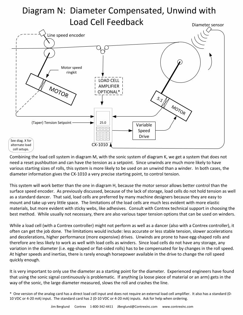
Diagram N: Diameter Compensated, Unwind with Load Cell Feedback
5:1 MOTOR
MOTOR
Motor speed ringkit
Line speed encoder
Variable Speed Drive
25.0
LOAD CELLAMPLIFIEROPTIONAL*
Diameter sensor
(Taper) Tension Setpoint
Jim Berglund Contrex 1-800-342-4411 [email protected] www.contrexinc.com
Combining the load cell system in diagram M, with the sonic system of diagram K, we get a system that does not need a reset pushbutton and can have the tension as a setpoint. Since unwinds are much more likely to have various starting sizes of rolls, this system is more likely to be used on an unwind than a winder. In both cases, the diameter information gives the CX-1010 a very precise starting point, to control tension.
This system will work better than the one in diagram H, because the motor sensor allows better control than the surface speed encoder. As previously discussed, because of the lack of storage, load cells do not hold tension as well as a standard dancer. That said, load cells are preferred by many machine designers because they are easy to mount and take up very little space. The limitations of the load cells are much less evident with more elastic materials, but more evident with sticky webs, like adhesives. Consult with Contrex technical support in choosing the best method. While usually not necessary, there are also various taper tension options that can be used on winders.
While a load cell (with a Contrex controller) might not perform as well as a dancer (also with a Contrex controller), it often can get the job done. The limitations would include: less accurate or less stable tension, slower accelerations and decelerations, higher performance (more expensive) drives. Unwinds are prone to have egg-shaped rolls and therefore are less likely to work as well with load cells as winders. Since load cells do not have any storage, any variation in the diameter (i.e. egg-shaped or flat-sided rolls) has to be compensated for by changes in the roll speed. At higher speeds and inertias, there is rarely enough horsepower available in the drive to change the roll speed quickly enough.
It is very important to only use the diameter as a starting point for the diameter. Experienced engineers have found that using the sonic signal continuously is problematic. If anything (a loose piece of material or an arm) gets in the way of the sonic, the large diameter measured, slows the roll and crashes the line.
* One version of the analog card has a direct load cell input and does not require an external load cell amplifier. It also has a standard (0-10 VDC or 4-20 mA) input. The standard card has 2 (0-10 VDC or 4-20 mA) inputs. Ask for help when ordering.
CX-1010See diag. X for alternate load
cell setups.
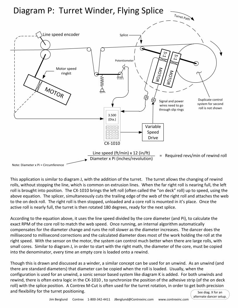
Diagram P: Turret Winder, Flying Splice
MOTOR
Motor speed ringkit
Line speed encoder
Variable Speed Drive
Potentiometer5:1 M
OTO
R5:1 M
OTO
R
Turret Path
Splice
3.500(Dia.)
Signal and power wires need to go through slip rings
Duplicate control system for second roll is not shown
Jim Berglund Contrex 1-800-342-4411 [email protected] www.contrexinc.com
This application is similar to diagram J, with the addition of the turret. The turret allows the changing of rewind rolls, without stopping the line, which is common on extrusion lines. When the far right roll is nearing full, the left roll is brought into position. The CX-1010 brings the left roll (often called the “on deck” roll) up to speed, using the above equation. The splicer, simultaneously cuts the trailing edge of the web of the right roll and attaches the web to the on deck roll. The right roll is then stopped, unloaded and a core roll is mounted in it’s place. Once the active roll is nearly full, the turret is then rotated 180 degrees, ready for the next splice.
According to the equation above, it uses the line speed divided by the core diameter (and Pi), to calculate the exact RPM of the core roll to match the web speed. Once running, an internal algorithm automatically compensates for the diameter change and runs the roll slower as the diameter increases. The dancer does the millisecond to millisecond corrections and the calculated diameter does most of the work holding the roll at the right speed. With the sensor on the motor, the system can control much better when there are large rolls, with small cores. Similar to diagram J, in order to start with the right math, the diameter of the core, must be copied into the denominator, every time an empty core is loaded onto a rewind.
Though this is drawn and discussed as a winder, a similar concept can be used for an unwind. As an unwind (and there are standard diameters) that diameter can be copied when the roll is loaded. Usually, when the configuration is used for an unwind, a sonic sensor based system like diagram K is added. For both unwinds and rewind, there is often extra logic in the CX-1010 , to synchronize the position of the adhesive strip (of the on deck roll) with the splice position. A Contrex M-Cut is often used for the turret rotation, in order to get both precision and flexibility for the turret positioning.
Line speed (ft/min) x 12 (in/ft)Diameter x Pi (inches/revolution)
= Required revs/min of rewind roll
Note: Diameter x Pi = Circumference
CX-1010
See diag. X for an alternate dancer setup.
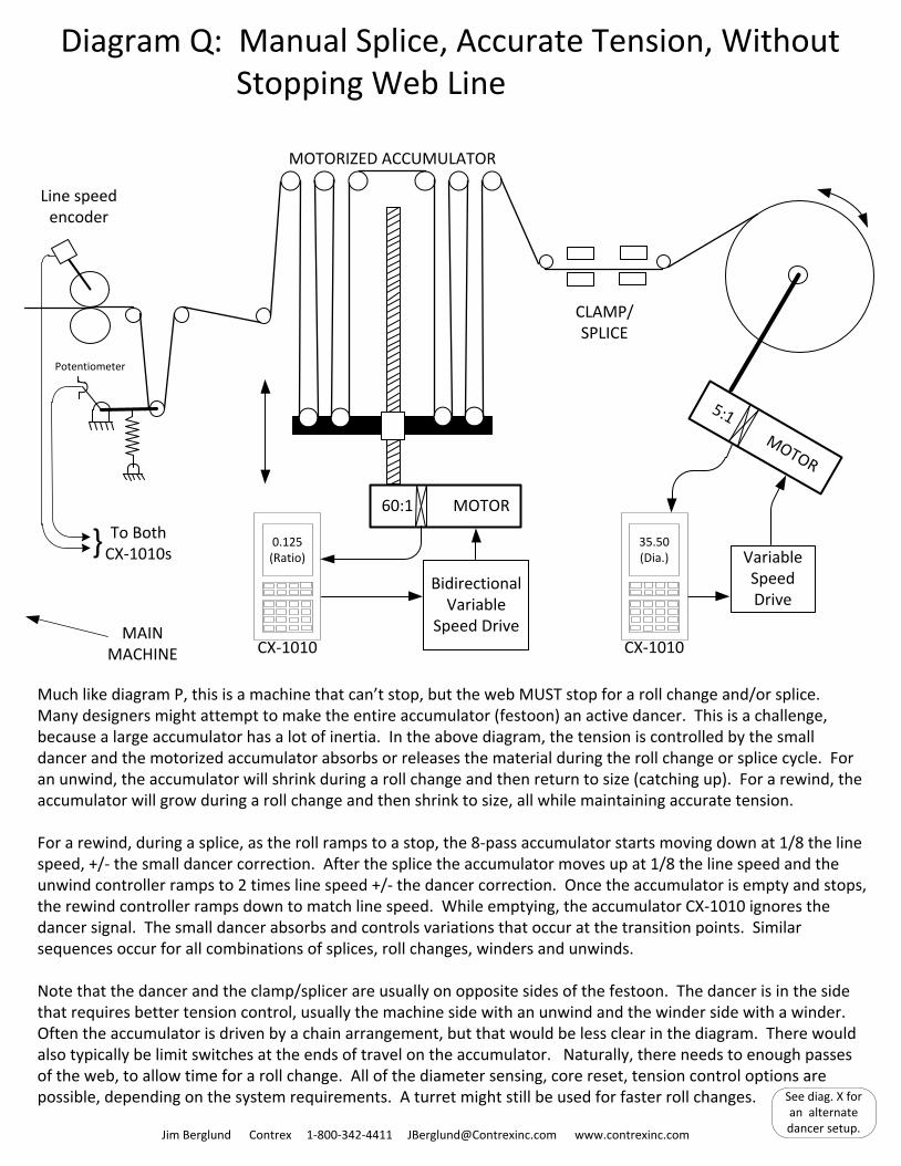
Diagram Q: Manual Splice, Accurate Tension, Without Stopping Web Line
Much like diagram P, this is a machine that can’t stop, but the web MUST stop for a roll change and/or splice. Many designers might attempt to make the entire accumulator (festoon) an active dancer. This is a challenge, because a large accumulator has a lot of inertia. In the above diagram, the tension is controlled by the small dancer and the motorized accumulator absorbs or releases the material during the roll change or splice cycle. For an unwind, the accumulator will shrink during a roll change and then return to size (catching up). For a rewind, the accumulator will grow during a roll change and then shrink to size, all while maintaining accurate tension.
For a rewind, during a splice, as the roll ramps to a stop, the 8-pass accumulator starts moving down at 1/8 the line speed, +/- the small dancer correction. After the splice the accumulator moves up at 1/8 the line speed and the unwind controller ramps to 2 times line speed +/- the dancer correction. Once the accumulator is empty and stops, the rewind controller ramps down to match line speed. While emptying, the accumulator CX-1010 ignores the dancer signal. The small dancer absorbs and controls variations that occur at the transition points. Similar sequences occur for all combinations of splices, roll changes, winders and unwinds.
Note that the dancer and the clamp/splicer are usually on opposite sides of the festoon. The dancer is in the side that requires better tension control, usually the machine side with an unwind and the winder side with a winder. Often the accumulator is driven by a chain arrangement, but that would be less clear in the diagram. There would also typically be limit switches at the ends of travel on the accumulator. Naturally, there needs to enough passes of the web, to allow time for a roll change. All of the diameter sensing, core reset, tension control options are possible, depending on the system requirements. A turret might still be used for faster roll changes.
Jim Berglund Contrex 1-800-342-4411 [email protected] www.contrexinc.com
Line speed encoder
5:1 MOTOR
Variable Speed Drive
Potentiometer
35.50(Dia.)
CX-1010
60:1 MOTOR
CLAMP/ SPLICE
} To Both CX-1010s
Bidirectional Variable
Speed Drive
0.125 (Ratio)
CX-1010MAIN
MACHINE
MOTORIZED ACCUMULATOR
See diag. X for an alternate dancer setup.
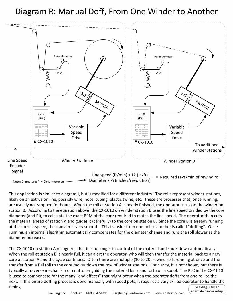
Diagram R: Manual Doff, From One Winder to Another
This application is similar to diagram J, but is modified for a different industry. The rolls represent winder stations, likely on an extrusion line, possibly wire, hose, tubing, plastic twine, etc. These are processes that, once running, are usually not stopped for hours. When the roll at station A is nearly finished, the operator turns on the winder on station B. According to the equation above, the CX-1010 on winder station B uses the line speed divided by the core diameter (and Pi), to calculate the exact RPM of the core required to match the line speed. The operator then cuts the material ahead of station A and guides it (carefully) to the core on station B. Since the core B is already running at the correct speed, the transfer is very smooth. This transfer from one roll to another is called “doffing”. Once running, an internal algorithm automatically compensates for the diameter change and runs the roll slower as the diameter increases.
The CX-1010 on station A recognizes that it is no longer in control of the material and shuts down automatically. When the roll at station B is nearly full, it can alert the operator, who will then transfer the material back to a new core at station A and the cycle continues. Often there are multiple (10 to 20) rewind rolls running at once and the transfer from a full roll to the core moves down the row of winder stations. For clarity, it is not shown, but there is typically a traverse mechanism or controller guiding the material back and forth on a spool. The PLC in the CX-1010 is used to compensate for the many “end effects” that might occur when the operator doffs from one roll to the next. If this entire doffing process is done manually with speed pots, it requires a very skilled operator to handle the timing.
Jim Berglund Contrex 1-800-342-4411 [email protected] www.contrexinc.com
Line speed (ft/min) x 12 (in/ft)Diameter x Pi (inches/revolution)
= Required revs/min of rewind rollNote: Diameter x Pi = Circumference
5:1 MOTOR
Variable Speed Drive
Potentiometer
25.50(Dia.)
CX-1010
5:1 MOTOR
Variable Speed Drive
Potentiometer
3.50(Dia.)
CX-1010
Winder Station BWinder Station A
To additional winder stations
Line Speed Encoder
Signal
See diag. X for an alternate dancer setup.
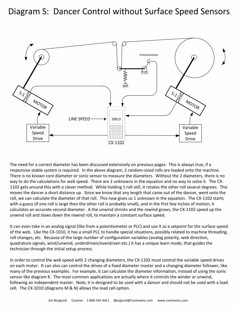
Diagram S: Dancer Control without Surface Speed Sensors
5:1 MOTOR
Variable Speed Drive
5:1 MOTOR
Variable Speed Drive
500.0
Potentiometer
Jim Berglund Contrex 1-800-342-4411 [email protected] www.contrexinc.com
CX-1102
The need for a correct diameter has been discussed extensively on previous pages. This is always true, if a responsive stable system is required. In the above diagram, 2 random-sized rolls are loaded onto the machine. There is no known core diameter or sonic sensor to measure the diameters. Without the 2 diameters, there is no way to do the calculations for web speed. There are 2 unknowns in the equation and no way to solve it. The CX-1102 gets around this with a clever method. While holding 1 roll still, it rotates the other roll several degrees. This moves the dancer a short distance up. Since we know that any length that came out of the dancer, went onto the roll, we can calculate the diameter of that roll. This now gives us 1 unknown in the equation. The CX-1102 starts with a guess (if one roll is large then the other roll is probably small), and in the first few inches of motion, it calculates an accurate second diameter. A the unwind shrinks and the rewind grows, the CX-1102 speed up the unwind roll and slows down the rewind roll, to maintain a constant surface speed.
It can even take in an analog signal (like from a potentiometer or PLC) and use it as a setpoint for the surface speed of the web. Like the CX-1010, it has a small PLC to handle special situations, possibly related to machine threading, roll changes, etc. Because of the large number of configuration variables (analog polarity, web direction, quadrature signals, wind/unwind, underdriven/overdriven etc.) it has a unique learn mode, that guides the technician through the initial setup process.
In order to control the web speed with 2 changing diameters, the CX-1102 must control the variable speed drives on each motor. It can also can control the drives of a fixed diameter master and a changing diameter follower, like many of the previous examples. For example, it can calculate the diameter information, instead of using the sonic sensor like diagram K. The most common applications are actually where it controls the winder or unwind, following an independent master. Note, it is designed to be used with a dancer and should not be used with a load cell. The CX-1010 (diagrams M & N) allows the load cell option.
LINE SPEED
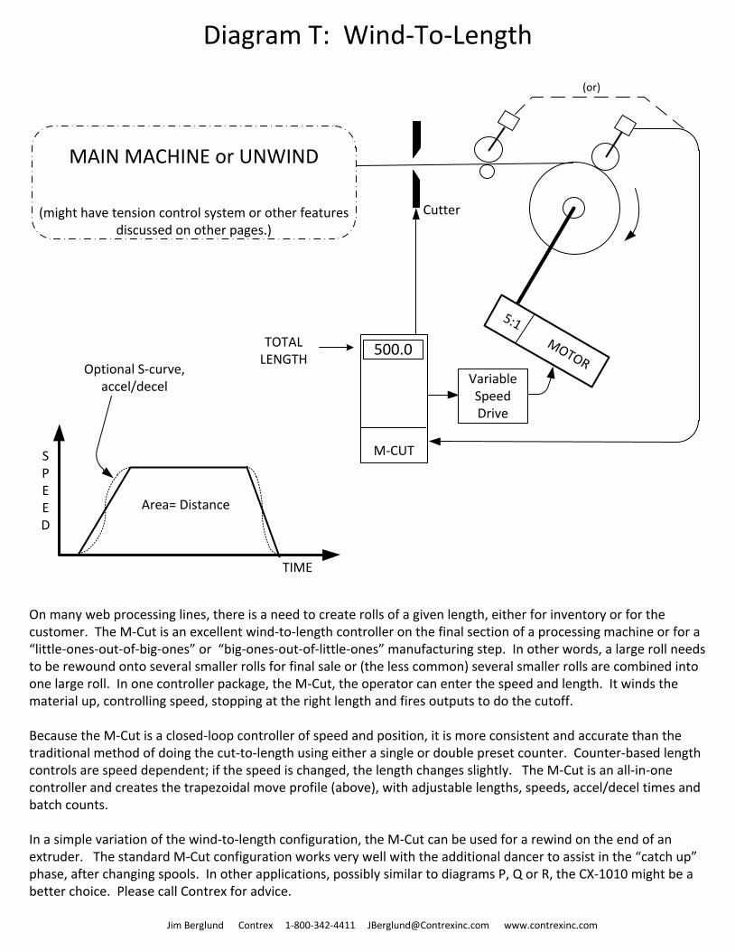
Diagram T: Wind-To-Length
Jim Berglund Contrex 1-800-342-4411 [email protected] www.contrexinc.com
5:1 MOTORVariable Speed Drive
(or)
M-CUT
500.0
MAIN MACHINE or UNWIND
(might have tension control system or other features discussed on other pages.)
SPEED
TIME
Area= Distance
Optional S-curve,accel/decel
On many web processing lines, there is a need to create rolls of a given length, either for inventory or for the customer. The M-Cut is an excellent wind-to-length controller on the final section of a processing machine or for a “little-ones-out-of-big-ones” or “big-ones-out-of-little-ones” manufacturing step. In other words, a large roll needs to be rewound onto several smaller rolls for final sale or (the less common) several smaller rolls are combined into one large roll. In one controller package, the M-Cut, the operator can enter the speed and length. It winds the material up, controlling speed, stopping at the right length and fires outputs to do the cutoff.
Because the M-Cut is a closed-loop controller of speed and position, it is more consistent and accurate than the traditional method of doing the cut-to-length using either a single or double preset counter. Counter-based length controls are speed dependent; if the speed is changed, the length changes slightly. The M-Cut is an all-in-one controller and creates the trapezoidal move profile (above), with adjustable lengths, speeds, accel/decel times and batch counts.
In a simple variation of the wind-to-length configuration, the M-Cut can be used for a rewind on the end of an extruder. The standard M-Cut configuration works very well with the additional dancer to assist in the “catch up” phase, after changing spools. In other applications, possibly similar to diagrams P, Q or R, the CX-1010 might be a better choice. Please call Contrex for advice.
Cutter
TOTALLENGTH
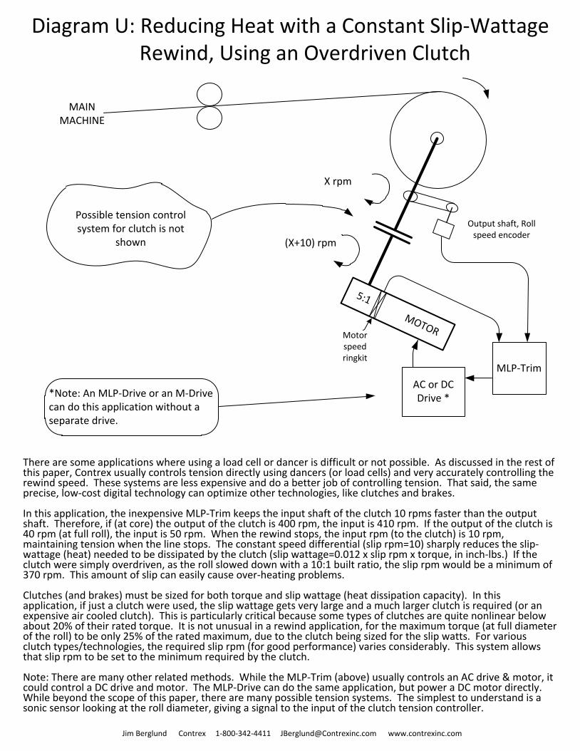
There are some applications where using a load cell or dancer is difficult or not possible. As discussed in the rest of this paper, Contrex usually controls tension directly using dancers (or load cells) and very accurately controlling the rewind speed. These systems are less expensive and do a better job of controlling tension. That said, the same precise, low-cost digital technology can optimize other technologies, like clutches and brakes.
In this application, the inexpensive MLP-Trim keeps the input shaft of the clutch 10 rpms faster than the output shaft. Therefore, if (at core) the output of the clutch is 400 rpm, the input is 410 rpm. If the output of the clutch is 40 rpm (at full roll), the input is 50 rpm. When the rewind stops, the input rpm (to the clutch) is 10 rpm, maintaining tension when the line stops. The constant speed differential (slip rpm=10) sharply reduces the slip-wattage (heat) needed to be dissipated by the clutch (slip wattage=0.012 x slip rpm x torque, in inch-lbs.) If the clutch were simply overdriven, as the roll slowed down with a 10:1 built ratio, the slip rpm would be a minimum of 370 rpm. This amount of slip can easily cause over-heating problems.
Clutches (and brakes) must be sized for both torque and slip wattage (heat dissipation capacity). In this application, if just a clutch were used, the slip wattage gets very large and a much larger clutch is required (or an expensive air cooled clutch). This is particularly critical because some types of clutches are quite nonlinear below about 20% of their rated torque. It is not unusual in a rewind application, for the maximum torque (at full diameter of the roll) to be only 25% of the rated maximum, due to the clutch being sized for the slip watts. For various clutch types/technologies, the required slip rpm (for good performance) varies considerably. This system allows that slip rpm to be set to the minimum required by the clutch.
Note: There are many other related methods. While the MLP-Trim (above) usually controls an AC drive & motor, it could control a DC drive and motor. The MLP-Drive can do the same application, but power a DC motor directly. While beyond the scope of this paper, there are many possible tension systems. The simplest to understand is a sonic sensor looking at the roll diameter, giving a signal to the input of the clutch tension controller.
5:1 MOTOR
Diagram U: Reducing Heat with a Constant Slip-Wattage Rewind, Using an Overdriven Clutch
MLP-Trim
Output shaft, Roll speed encoder
Motor speed ringkit
X rpm
(X+10) rpm
Possible tension control system for clutch is not
shown
AC or DC Drive **Note: An MLP-Drive or an M-Drive
can do this application without a separate drive.
Jim Berglund Contrex 1-800-342-4411 [email protected] www.contrexinc.com
MAIN MACHINE
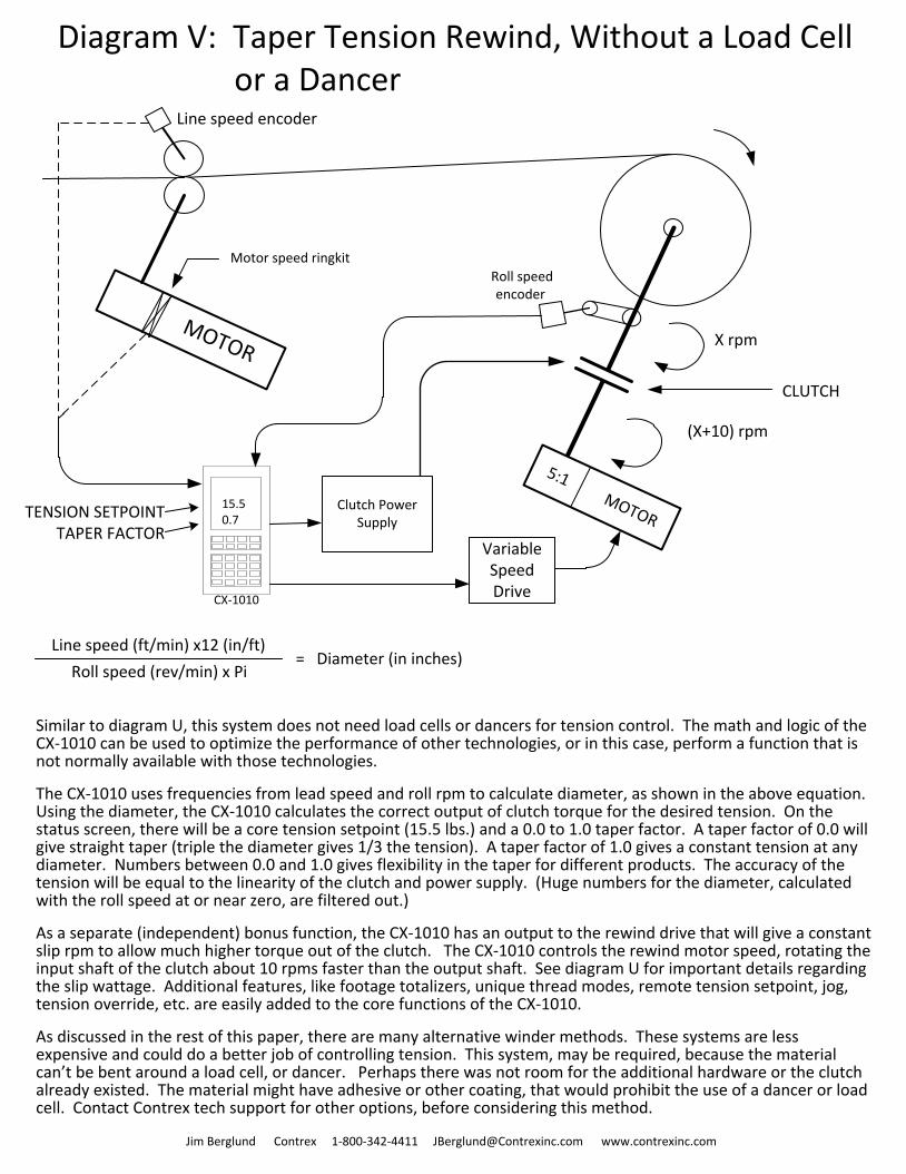
Similar to diagram U, this system does not need load cells or dancers for tension control. The math and logic of the CX-1010 can be used to optimize the performance of other technologies, or in this case, perform a function that is not normally available with those technologies.
The CX-1010 uses frequencies from lead speed and roll rpm to calculate diameter, as shown in the above equation. Using the diameter, the CX-1010 calculates the correct output of clutch torque for the desired tension. On the status screen, there will be a core tension setpoint (15.5 lbs.) and a 0.0 to 1.0 taper factor. A taper factor of 0.0 will give straight taper (triple the diameter gives 1/3 the tension). A taper factor of 1.0 gives a constant tension at any diameter. Numbers between 0.0 and 1.0 gives flexibility in the taper for different products. The accuracy of the tension will be equal to the linearity of the clutch and power supply. (Huge numbers for the diameter, calculated with the roll speed at or near zero, are filtered out.)
As a separate (independent) bonus function, the CX-1010 has an output to the rewind drive that will give a constant slip rpm to allow much higher torque out of the clutch. The CX-1010 controls the rewind motor speed, rotating the input shaft of the clutch about 10 rpms faster than the output shaft. See diagram U for important details regarding the slip wattage. Additional features, like footage totalizers, unique thread modes, remote tension setpoint, jog, tension override, etc. are easily added to the core functions of the CX-1010.
As discussed in the rest of this paper, there are many alternative winder methods. These systems are less expensive and could do a better job of controlling tension. This system, may be required, because the material can’t be bent around a load cell, or dancer. Perhaps there was not room for the additional hardware or the clutch already existed. The material might have adhesive or other coating, that would prohibit the use of a dancer or load cell. Contact Contrex tech support for other options, before considering this method.
Diagram V: Taper Tension Rewind, Without a Load Cell or a Dancer
5:1 MOTOR
MOTOR
Roll speed encoder
X rpm
(X+10) rpm
Motor speed ringkit
15.50.7
CX-1010
Clutch Power Supply
Line speed encoder
Variable Speed Drive
CLUTCH
Jim Berglund Contrex 1-800-342-4411 [email protected] www.contrexinc.com
TENSION SETPOINTTAPER FACTOR
= Diameter (in inches)Line speed (ft/min) x12 (in/ft)
Roll speed (rev/min) x Pi
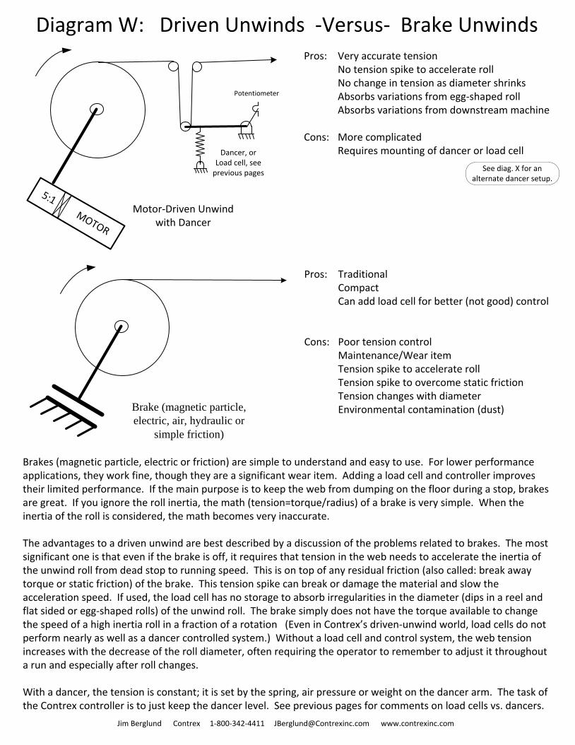
Pros: Very accurate tensionNo tension spike to accelerate roll No change in tension as diameter shrinksAbsorbs variations from egg-shaped rollAbsorbs variations from downstream machine
Cons: More complicatedRequires mounting of dancer or load cell
Brakes (magnetic particle, electric or friction) are simple to understand and easy to use. For lower performance applications, they work fine, though they are a significant wear item. Adding a load cell and controller improves their limited performance. If the main purpose is to keep the web from dumping on the floor during a stop, brakes are great. If you ignore the roll inertia, the math (tension=torque/radius) of a brake is very simple. When the inertia of the roll is considered, the math becomes very inaccurate.
The advantages to a driven unwind are best described by a discussion of the problems related to brakes. The most significant one is that even if the brake is off, it requires that tension in the web needs to accelerate the inertia of the unwind roll from dead stop to running speed. This is on top of any residual friction (also called: break away torque or static friction) of the brake. This tension spike can break or damage the material and slow the acceleration speed. If used, the load cell has no storage to absorb irregularities in the diameter (dips in a reel and flat sided or egg-shaped rolls) of the unwind roll. The brake simply does not have the torque available to change the speed of a high inertia roll in a fraction of a rotation (Even in Contrex’s driven-unwind world, load cells do not perform nearly as well as a dancer controlled system.) Without a load cell and control system, the web tension increases with the decrease of the roll diameter, often requiring the operator to remember to adjust it throughout a run and especially after roll changes.
With a dancer, the tension is constant; it is set by the spring, air pressure or weight on the dancer arm. The task of the Contrex controller is to just keep the dancer level. See previous pages for comments on load cells vs. dancers.
Pros: TraditionalCompactCan add load cell for better (not good) control
Cons: Poor tension controlMaintenance/Wear itemTension spike to accelerate rollTension spike to overcome static friction Tension changes with diameterEnvironmental contamination (dust)
Potentiometer
5:1 MOTOR
Motor-Driven Unwind with Dancer
Dancer, or Load cell, see
previous pages
Diagram W: Driven Unwinds -Versus- Brake Unwinds
Jim Berglund Contrex 1-800-342-4411 [email protected] www.contrexinc.com
Brake (magnetic particle,
electric, air, hydraulic or
simple friction)
See diag. X for an alternate dancer setup.
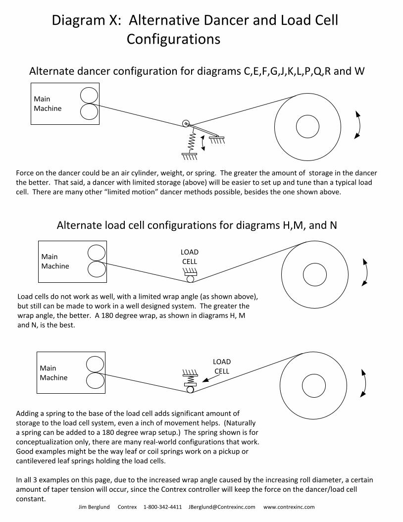
Adding a spring to the base of the load cell adds significant amount of storage to the load cell system, even a inch of movement helps. (Naturally a spring can be added to a 180 degree wrap setup.) The spring shown is for conceptualization only, there are many real-world configurations that work. Good examples might be the way leaf or coil springs work on a pickup or cantilevered leaf springs holding the load cells.
Diagram X: Alternative Dancer and Load Cell Configurations
MainMachine
Alternate dancer configuration for diagrams C,E,F,G,J,K,L,P,Q,R and W
Force on the dancer could be an air cylinder, weight, or spring. The greater the amount of storage in the dancer the better. That said, a dancer with limited storage (above) will be easier to set up and tune than a typical load cell. There are many other “limited motion” dancer methods possible, besides the one shown above.
MainMachine
LOAD CELL
Alternate load cell configurations for diagrams H,M, and N
MainMachine
LOAD CELL
Jim Berglund Contrex 1-800-342-4411 [email protected] www.contrexinc.com
Load cells do not work as well, with a limited wrap angle (as shown above), but still can be made to work in a well designed system. The greater the wrap angle, the better. A 180 degree wrap, as shown in diagrams H, M and N, is the best.
In all 3 examples on this page, due to the increased wrap angle caused by the increasing roll diameter, a certain amount of taper tension will occur, since the Contrex controller will keep the force on the dancer/load cell constant.