wind tunnel instructions - stem-az.orgstem-az.org/resources/wind-tunnel-instructions.pdf1 a table...
TRANSCRIPT
1
A Table Top Wind Tunnel You Can Build
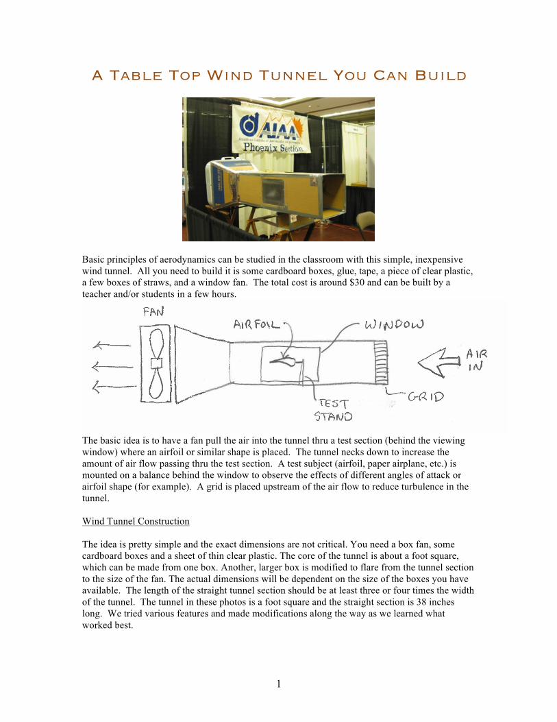
Basic principles of aerodynamics can be studied in the classroom with this simple, inexpensive wind tunnel. All you need to build it is some cardboard boxes, glue, tape, a piece of clear plastic, a few boxes of straws, and a window fan. The total cost is around $30 and can be built by a teacher and/or students in a few hours.
The basic idea is to have a fan pull the air into the tunnel thru a test section (behind the viewing window) where an airfoil or similar shape is placed. The tunnel necks down to increase the amount of air flow passing thru the test section. A test subject (airfoil, paper airplane, etc.) is mounted on a balance behind the window to observe the effects of different angles of attack or airfoil shape (for example). A grid is placed upstream of the air flow to reduce turbulence in the tunnel. Wind Tunnel Construction The idea is pretty simple and the exact dimensions are not critical. You need a box fan, some cardboard boxes and a sheet of thin clear plastic. The core of the tunnel is about a foot square, which can be made from one box. Another, larger box is modified to flare from the tunnel section to the size of the fan. The actual dimensions will be dependent on the size of the boxes you have available. The length of the straight tunnel section should be at least three or four times the width of the tunnel. The tunnel in these photos is a foot square and the straight section is 38 inches long. We tried various features and made modifications along the way as we learned what worked best.
2
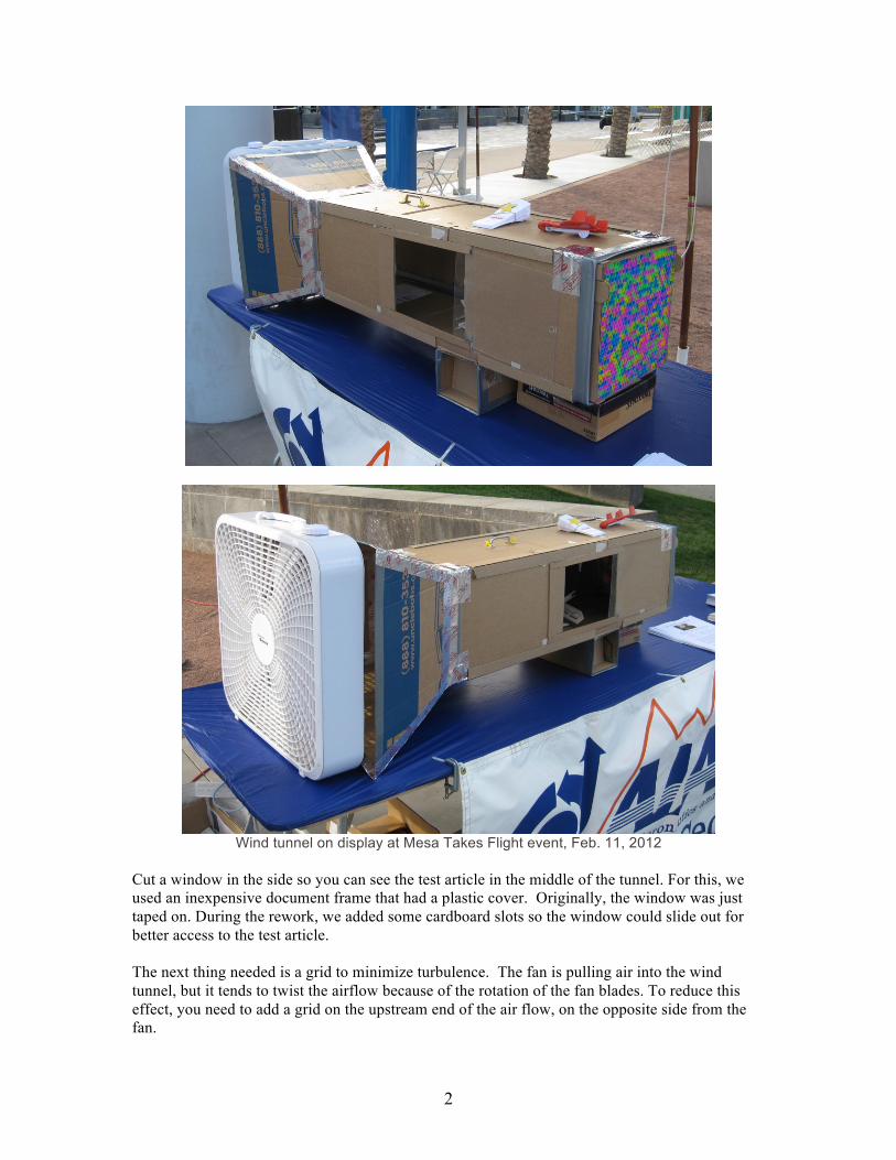
Wind tunnel on display at Mesa Takes Flight event, Feb. 11, 2012
Cut a window in the side so you can see the test article in the middle of the tunnel. For this, we used an inexpensive document frame that had a plastic cover. Originally, the window was just taped on. During the rework, we added some cardboard slots so the window could slide out for better access to the test article. The next thing needed is a grid to minimize turbulence. The fan is pulling air into the wind tunnel, but it tends to twist the airflow because of the rotation of the fan blades. To reduce this effect, you need to add a grid on the upstream end of the air flow, on the opposite side from the fan.
3
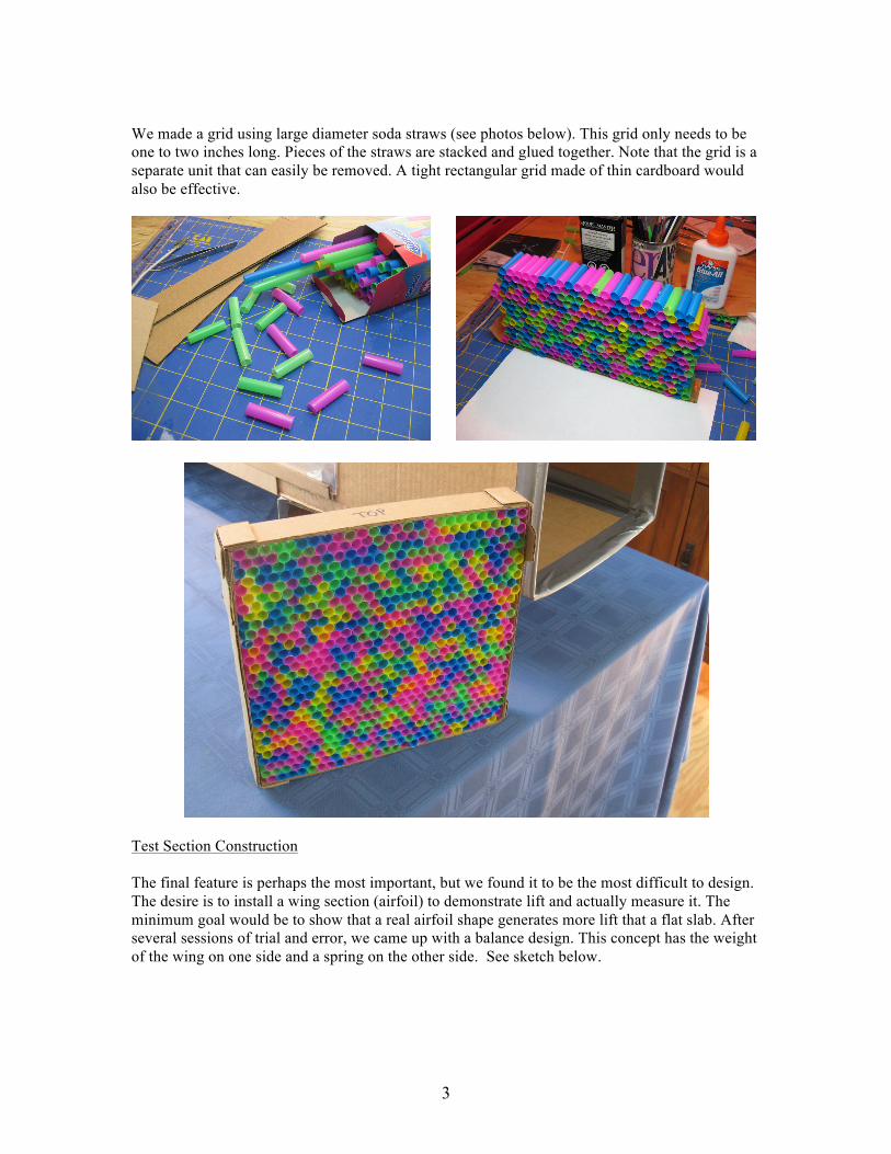
We made a grid using large diameter soda straws (see photos below). This grid only needs to be one to two inches long. Pieces of the straws are stacked and glued together. Note that the grid is a separate unit that can easily be removed. A tight rectangular grid made of thin cardboard would also be effective.
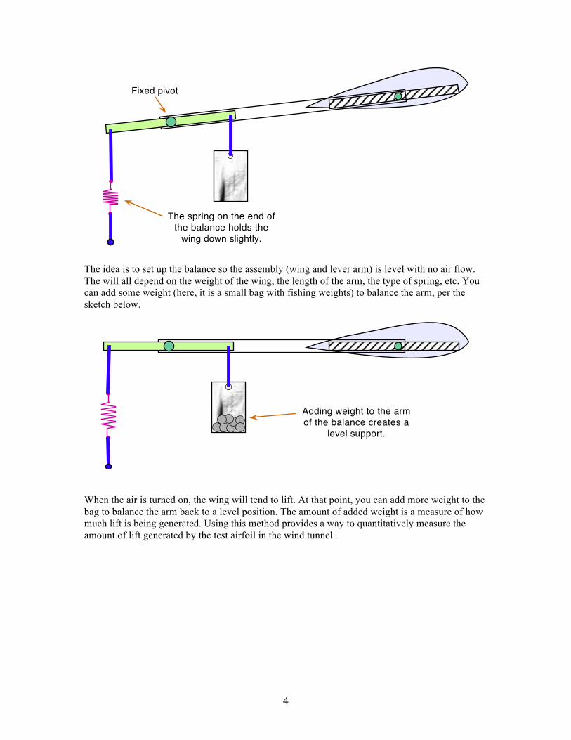
Test Section Construction The final feature is perhaps the most important, but we found it to be the most difficult to design. The desire is to install a wing section (airfoil) to demonstrate lift and actually measure it. The minimum goal would be to show that a real airfoil shape generates more lift that a flat slab. After several sessions of trial and error, we came up with a balance design. This concept has the weight of the wing on one side and a spring on the other side. See sketch below.
4
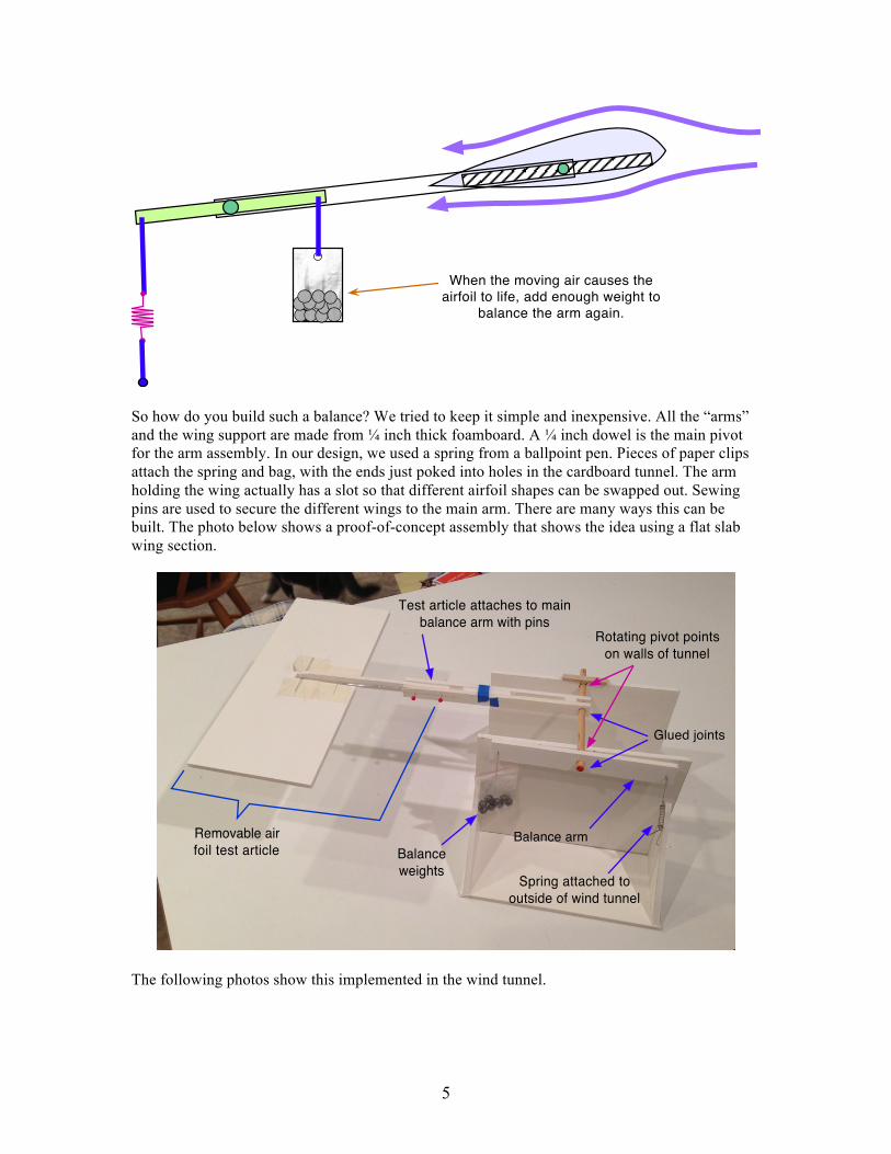
The idea is to set up the balance so the assembly (wing and lever arm) is level with no air flow. The will all depend on the weight of the wing, the length of the arm, the type of spring, etc. You can add some weight (here, it is a small bag with fishing weights) to balance the arm, per the sketch below.
When the air is turned on, the wing will tend to lift. At that point, you can add more weight to the bag to balance the arm back to a level position. The amount of added weight is a measure of how much lift is being generated. Using this method provides a way to quantitatively measure the amount of lift generated by the test airfoil in the wind tunnel.
The spring on the end of the balance holds the
wing down slightly.
Fixed pivot
Adding weight to the arm of the balance creates a
level support.
5
So how do you build such a balance? We tried to keep it simple and inexpensive. All the “arms” and the wing support are made from ¼ inch thick foamboard. A ¼ inch dowel is the main pivot for the arm assembly. In our design, we used a spring from a ballpoint pen. Pieces of paper clips attach the spring and bag, with the ends just poked into holes in the cardboard tunnel. The arm holding the wing actually has a slot so that different airfoil shapes can be swapped out. Sewing pins are used to secure the different wings to the main arm. There are many ways this can be built. The photo below shows a proof-of-concept assembly that shows the idea using a flat slab wing section.
The following photos show this implemented in the wind tunnel.
When the moving air causes the airfoil to life, add enough weight to
balance the arm again.
Removable air foil test article Balance
weights
Glued joints
Balance arm
Spring attached to outside of wind tunnel
Test article attaches to main balance arm with pins
Rotating pivot points on walls of tunnel
6
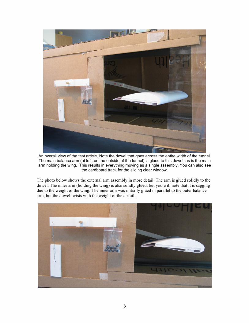
An overall view of the test article. Note the dowel that goes across the entire width of the tunnel. The main balance arm (at left, on the outside of the tunnel) is glued to this dowel, as is the main arm holding the wing. This results in everything moving as a single assembly. You can also see
the cardboard track for the sliding clear window. The photo below shows the external arm assembly in more detail. The arm is glued solidly to the dowel. The inner arm (holding the wing) is also solidly glued, but you will note that it is sagging due to the weight of the wing. The inner arm was initially glued in parallel to the outer balance arm, but the dowel twists with the weight of the airfoil.
7
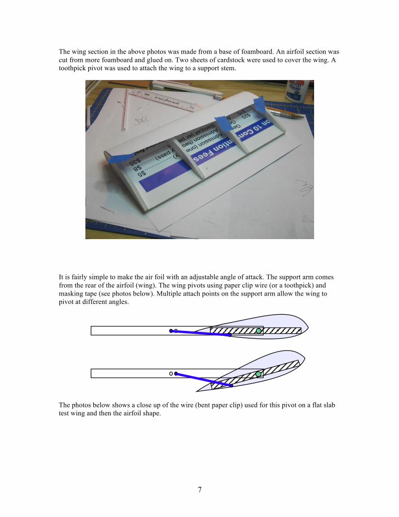
The wing section in the above photos was made from a base of foamboard. An airfoil section was cut from more foamboard and glued on. Two sheets of cardstock were used to cover the wing. A toothpick pivot was used to attach the wing to a support stem.
It is fairly simple to make the air foil with an adjustable angle of attack. The support arm comes from the rear of the airfoil (wing). The wing pivots using paper clip wire (or a toothpick) and masking tape (see photos below). Multiple attach points on the support arm allow the wing to pivot at different angles.
The photos below shows a close up of the wire (bent paper clip) used for this pivot on a flat slab test wing and then the airfoil shape.
8
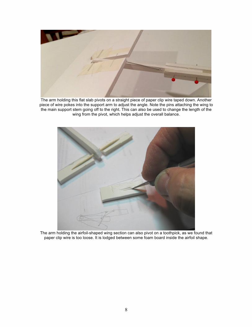
The arm holding this flat slab pivots on a straight piece of paper clip wire taped down. Another
piece of wire pokes into the support arm to adjust the angle. Note the pins attaching the wing to the main support stem going off to the right. This can also be used to change the length of the
wing from the pivot, which helps adjust the overall balance.
The arm holding the airfoil-shaped wing section can also pivot on a toothpick, as we found that
paper clip wire is too loose. It is lodged between some foam board inside the airfoil shape.
9
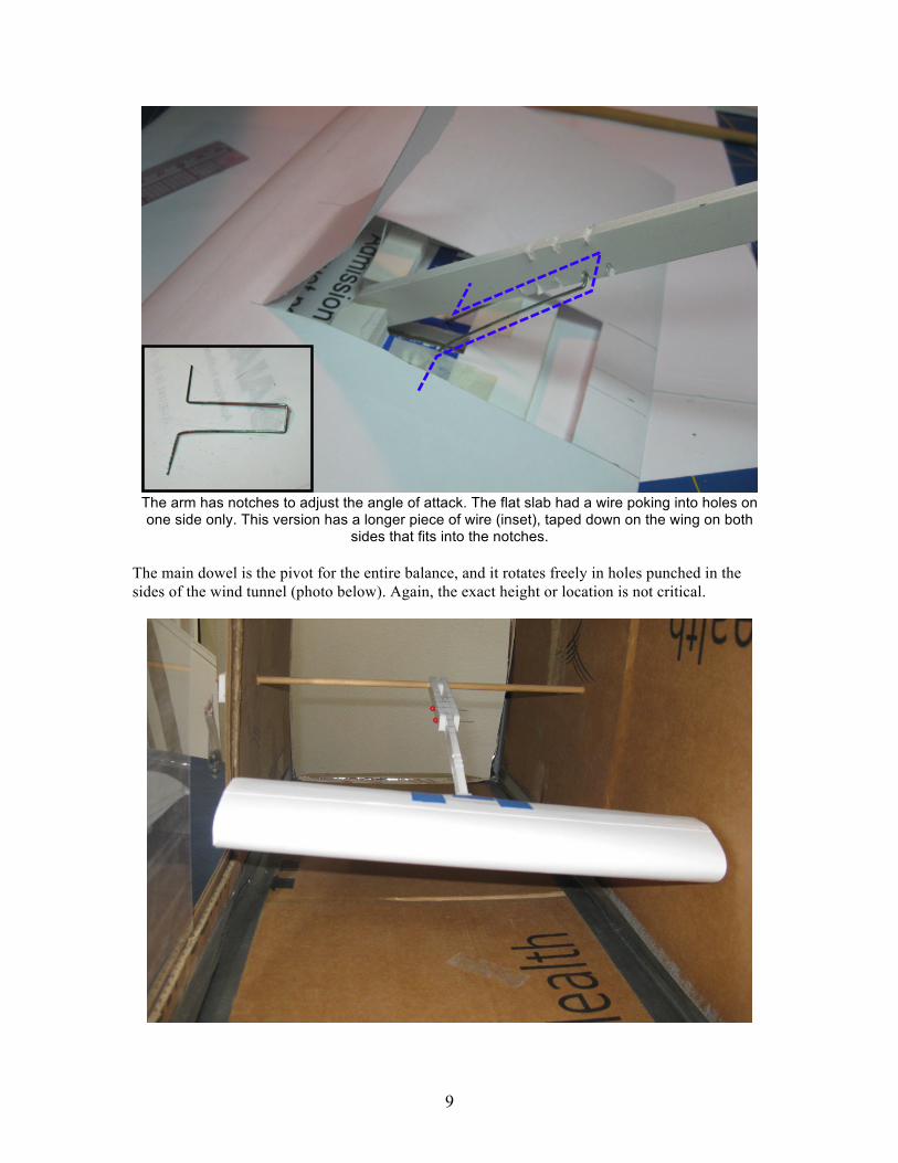
The arm has notches to adjust the angle of attack. The flat slab had a wire poking into holes on one side only. This version has a longer piece of wire (inset), taped down on the wing on both
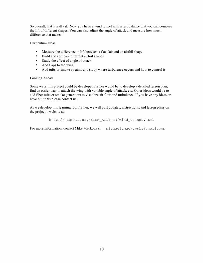
sides that fits into the notches. The main dowel is the pivot for the entire balance, and it rotates freely in holes punched in the sides of the wind tunnel (photo below). Again, the exact height or location is not critical.
10
So overall, that’s really it. Now you have a wind tunnel with a test balance that you can compare the lift of different shapes. You can also adjust the angle of attack and measure how much difference that makes. Curriculum Ideas
• Measure the difference in lift between a flat slab and an airfoil shape • Build and compare different airfoil shapes • Study the effect of angle of attack • Add flaps to the wing • Add tufts or smoke streams and study where turbulence occurs and how to control it
Looking Ahead Some ways this project could be developed further would be to develop a detailed lesson plan, find an easier way to attach the wing with variable angle of attack, etc. Other ideas would be to add fiber tufts or smoke generators to visualize air flow and turbulence. If you have any ideas or have built this please contact us. As we develop this learning tool further, we will post updates, instructions, and lesson plans on the project’s website at:
http://stem-az.org/STEM_Arizona/Wind_Tunnel.html For more information, contact Mike Mackowski: [email protected]