the e80 wind tunnel experiment - harvey mudd · pdf filethe e80 wind tunnel experiment ......
TRANSCRIPT

The E80 Wind Tunnel Experiment the experience will blow you away���
by Professor Duron
Spring 2012

Objectives
• To familiarize the student with the basic operation and instrumentation of the HMC wind tunnel
• To examine the lift and drag forces on standard shapes in a flow
field, and obtain a qualitative relationship between lift and drag coefficients
• To evaluate lift and drag forces on a rocket body, evaluate pitot
tube measurements, and complete a design problem

Bernoulli’s Equation

A Standard Shape (airfoil)
• Airfoils provide lift
Streamlines Flow over a curved surface is faster and the Bernoulli effect results in lower pressure over the upper surface
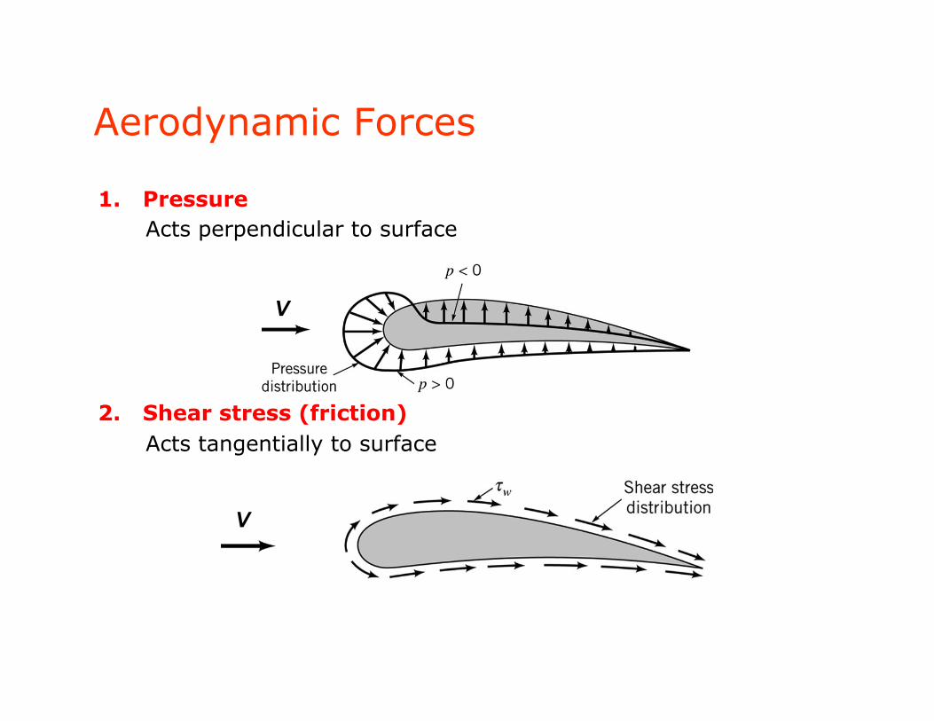
1. Pressure Acts perpendicular to surface
2. Shear stress (friction) Acts tangentially to surface
Aerodynamic Forces
V
V

• The sum of pressure and shear stress is the resultant force. It is split into two components:
1. Lift: The component of resultant force that is perpendicular to the incoming velocity vector (free stream).
2. Drag: The component of resultant force that is parallel to the incoming velocity vector (free stream).
Lift and Drag
V
Combined with the right weight and thrust – we can fly!

Calculating Lift and Drag
D = dFx = pcosθ dA + τw sinθ dA∫∫∫
L = dFy = − psinθ dA + τw cosθ dA∫∫∫
V
Drag force
Lift force
Need to resolve these components properly on the rocket during your wind tunnel tests

Lift and Drag
• Lift force L and drag force D cannot be calculated without detailed information about shear stress and pressure distributions on a body and are computationally challenging even with this information.
• Instead, Lift and Drag are represented by nondimensional coefficients defined by the ratio of lift or drag force and fluid kinetic energy.
• where is the lift or drag force, measured in pounds or Newtons; ρ is the fluid density (in slugs/ft3 or kg/m3), V is the average flow speed (in ft/s or m/s), and A is the area (ft2 or m2) normal to the force, or the characteristic area of the object.
AVF
C DLDL 2
21
,, ρ=
DLF ,

Balancing Lift, Drag - Stall
• http://www.youtube.com/watch?v=_rQAUHSTJIQ&feature=related
• http://www.youtube.com/watch?v=WFcW5-1NP60

Lift, Drag, Attack Angle
Experimental Fluid Dynamics
• Osborne Reynolds (University of Manchester, 1883) discovered that, – if the same atmospheric pressure were used for experiments with wind
tunnel models as a full-size airplane would encounter under actual conditions, the results would be invalid.
• For the results to be valid, – the air density inside the wind tunnel must be increased by the same
proportion as the model is smaller than the actual airplane. • Practically, if a model is 1/10th the size of a full size plane, the flow
velocity must be increased by a factor of 10 to get wind tunnel results that are valid in regular atmospheric conditions with a full size plane.
• Two similarly shaped but different sized objects would have the same aerodynamics as long as the Reynolds Numbers for the two objects matched.

Reynolds Number
• The Reynolds Number quantifies the relative significance of inertia (fluid acceleration) and viscous effects (e.g. drag force, or boundary layer thickness around an object).
• If a model flow has the same Reynolds Number as the flow it is meant to represent, the flow patterns and quantitative pressures and forces will be equivalent.
• Reynolds Number is defined
• where are defined as the fluid density, viscosity (a measure of the fluid’s resistance to motion), the average fluid velocity, and some characteristic object length.
µρVd
effectsviscouseffectsinertial ==Re
dandV ,,, µρ
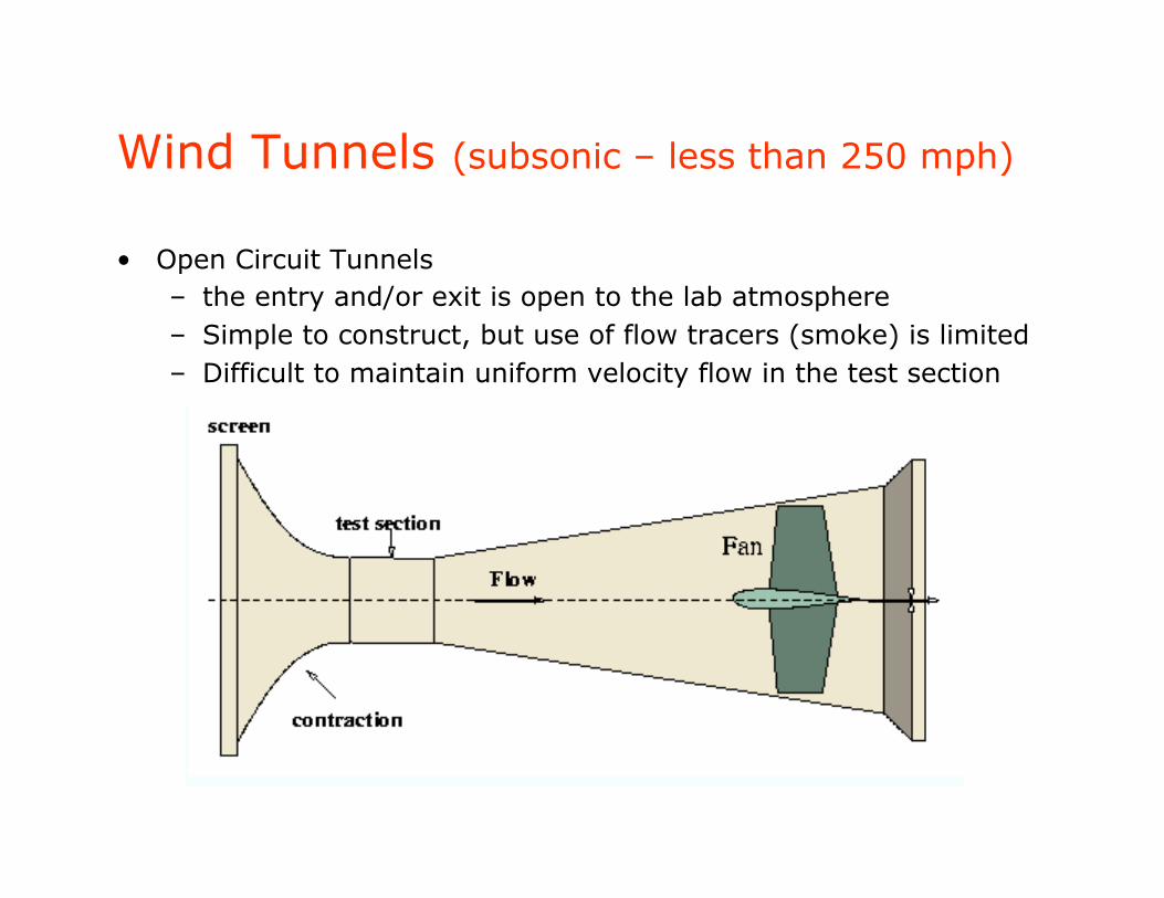
Wind Tunnels (subsonic – less than 250 mph)
• Open Circuit Tunnels – the entry and/or exit is open to the lab atmosphere – Simple to construct, but use of flow tracers (smoke) is limited – Difficult to maintain uniform velocity flow in the test section

Wind Tunnel (cont.)
• Close Circuit Tunnels – more uniform flow properties – more challenging to construct and maintain

The HMC Wind Tunnel
• Designed and constructed by HMC Students and former HMC Professor Jennifer Rossmann.
• The wind tunnel is a modified open circuit design with a test section that has a 1’ x 1’ cross section, and can achieve speeds up to 140 mph (Mach 0.2)

Instrumentation – Pitot Static Tube
Measures Aircraft Speed (speedometer)

Pitot Tube
• Several small holes are drilled around the outside of the tube, and a center hole is drilled down the tube axis. The outside holes are connected to one side of a manometer, and the center hole is kept separate from the outside holes and is connected to the other side of the manometer.
• Stagnation point A and point B are on the same streamline, so they can be modeled using Bernoulli’s equation (neglecting gravity effects)
PA + 0 = PB + 12 ρV
⇒V =
2 PA − PB( )ρ

From Russia With Love
• http://www.youtube.com/watch?v=DO3hnYJ7TUw

Dynamometer
• A two component force balance used to measure lift and drag forces.
• Forces generated by the model under test cause the deflection of two restrained cantilever beams (along the lift axis and the drag axis). Measurements of the resulting deflections can be used to estimate the applied forces.
• Linear Voltage Displacement Transducers (LVDTs) are used to measure the beam displacements.

LVDTs
• A typical LVDT consists of a transformer and a moving core. • The transformer consists of 3 symmetrically placed coils inside a
cylindrical shield of ferro-magnetic material rendering it impervious to humidity and ordinary magnetic interferences.
• The core is made of a nickel-iron alloy and is usually threaded internally to allow attachment to an external actuator (article under test).
• Advantages include – Frictionless movement – Long mechanical life – Infinite resolution – Null position stable – Frequency range 50Hz-25kHz

Safety
• Follow the Dress Code for E80 Lab • Never turn the FAN on without
– Checking to see that no loose objects are in the test chamber – Securing the test chamber cover plate – Making sure all test personnel are at a safe distance from the
wind tunnel itself (at least 24” in any direction) – Making sure the vent is clear – Making sure the article under test (AUT) is securely fastened
inside the test chamber

The Lab
• http://www.eng.hmc.edu/NewE80/WindTunnelLab.html

Extras…

Acknowledgements
• Dr. Jennifer Rossmann • Jake Pinheiro • NASA web sites

Induced Drag
• For a lifting wing, the pressure on the top of the wing is lower than the pressure below the wing. Near the wing tips, the air can move from the region of high pressure into the region of low pressure.
• Vortices are created at the wing tips. • If the atmosphere has high humidity, you
can sometimes see the vortex lines on an airliner during landing as long thin "clouds" leaving the wing tips.
• The wing tip vortices produce a down wash of air behind the wing which is very strong near the wing tips and decreases toward the wing root.
• The local angle of attack is increased by the induced flow of the down wash, giving an additional, downstream-facing drag force.
• This additional force is called induced drag because it faces downstream and has been "induced" by the action of the tip vortices.

Downwash
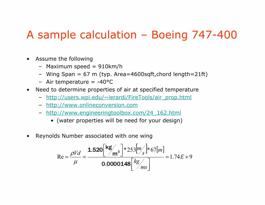
A sample calculation – Boeing 747-400
• Assume the following – Maximum speed = 910km/h – Wing Span = 67 m (typ. Area=4600sqft,chord length=21ft) – Air temperature = -40°C
• Need to determine properties of air at specified temperature – http://users.wpi.edu/~ierardi/FireTools/air_prop.html – http://www.onlineconversion.com – http://www.engineeringtoolbox.com/24_162.html
• (water properties will be need for your design)
• Reynolds Number associated with one wing
[ ] [ ]974.1
67*253*Re +=
⎥⎦⎤
⎢⎣⎡
⎥⎦⎤
⎢⎣⎡
== E
mskg
msm
Vd
0.0000148
mkg1.520 3
µρ

Demo
• FoilSim

Mach Number
• Aerodynamic forces also depend on the compressibility of the air or fluid.
• At low speeds (typically below 200 mph), the density of the fluid remains fairly constant. At high speeds, some of the object’s energy compresses the fluid and changes its density and alters the resulting force on the object.
• Near and beyond the speed of sound (approximately 700 mph), shock waves are produced affecting both lift and drag on the object.
• The important similarity parameter for compressibility is the Mach Number defined as the ratio of the object’s velocity to the speed of sound
cVM =

The Bernoulli Effect
• The air across the top of an airfoil experiences constricted flow lines and increased air speed relative to the wing.
• According to Bernoulli, this results in a decrease in pressure along
the top of the airfoil and provides a lift force.

Newton’s 3rd Law
• Lift results from the angle of attack. • The boundary layer of air on the airfoil and resulting downwash of
air behind the airfoil gives the air a downward force. • According to Newton’s 3rd Law, the airfoil experiences a force in
the opposite direction lifting the airfoil.

Bernoulli or Newton for Lift?
• Bernoulli’s equation is a statement of the principle of conservation of energy in fluids and has been shown to match pressure measurements around airfoils in wind tunnels and in flight.
• Newton’s 3rd law and the conservation of momentum are equally valid in the context of lift.
• German mathematician Kutta and Russian physicist Zhukovsky
independently developed the mathematical theory of lift that makes the connection between lift on an airfoil and the circulation around them.

Flow Patterns and Length Effect
• Flow patterns are shown on a Joukowsky foil of very great span (length).
• At high angles of attack, the boundary layer separates at the leading edge and stalls producing a drop in lift-to-drag ratio.
• Flow around a finite length wing is 3-D. The pressures above and below the wing interact with the surrounding air – particularly as you approach the wing tips.
• Leads to the concept of induced drag

What is a boundary layer?
• Aerodynamic forces depend on the viscosity of the air. As an object moves through the air, air molecules stick to the object’s surface.
• A layer of air is created near the surface that is referred to as a boundary layer. This boundary layer, in effect, changes the shape of the object since the flow reacts to the edge of the boundary layer as if it was the physical surface of the object.
• It is also possible for the boundary layer to lift off or even separate from the body creating an effective shape much different than the object’s physical shape.
• Boundary layers are very important in determining the lift and drag of an object.
• To determine and predict these conditions, aerodynamicists rely on wind tunnel testing and very sophisticated computer analyses.

Wind Tunnel Instrumentation
• A standard pitot probe measures pressure difference.
• A stagnation point exists at the nose of the probe where the flow velocity is zero and a small pressure tap measures the pressure at this point.
• Flow generally moves around the probe with some average speed and pressure .
• A differential manometer measures the difference between the two pressure which varies according to Bernoulli’s equation
opV
p
2
21 Vppo ρ=−

Re and Boundary Layer Flow Low Re Moderate Re
High Re