wda kit user manual
DESCRIPTION
WDA KIT User ManualTRANSCRIPT
IMPORTANT - PLEASE READ VERY CAREFULLY BEFORE SET UP
1.
2.
3.
Alarm Security and Insurance
Any alarm system is not a substitute for adequate insurance cover.
Please review your insurance needs and ensure adequate insurance for
your property, goods and persons.
Access To Your Property
Unwanted persons may enter your property via points of access which
are not protected by sensors or by disconnecting a sensor device.Please
ensure all locks on all doors and windows operate securely and additional
sensors are used to cover all access points.An evaluation of your security
needs by a security expert is recommended.
Batteries
This alarm system's wireless transmitters batteries and Main Unit phone
back-up batteries (not supplied) should be high quality heavy-duty (alk-
aline or lithium) batteries - AAA (1.5V) for the wireless PIR Monitor
Detectors and AA (1.5V) for the Main Unit phone. The expected life of
the batteries is a function of the use environment. All batteries should
be replaced at least annually.
While the PIR Motion Detectors have a low battery monitor when these
batteries require replacement, the monitor may fail to operate.
Always use heavy-duty (alkaline or lithium) batteries -do not use
rechargeable batteries.
Components
This alarm system is extremely reliable and subject to vigorous quality
control. However, due to the large number of components, the system
may fail to function due to the failure of a single component.
Criminal Intent
It is feasible for technologically-orientated persons of criminal intent to
develop techniques to reduce the effectiveness of any alarm security
system. It is therefore critical to periodically review your security needs
and the protection provided by this alarm system and to replace or
4.
5.
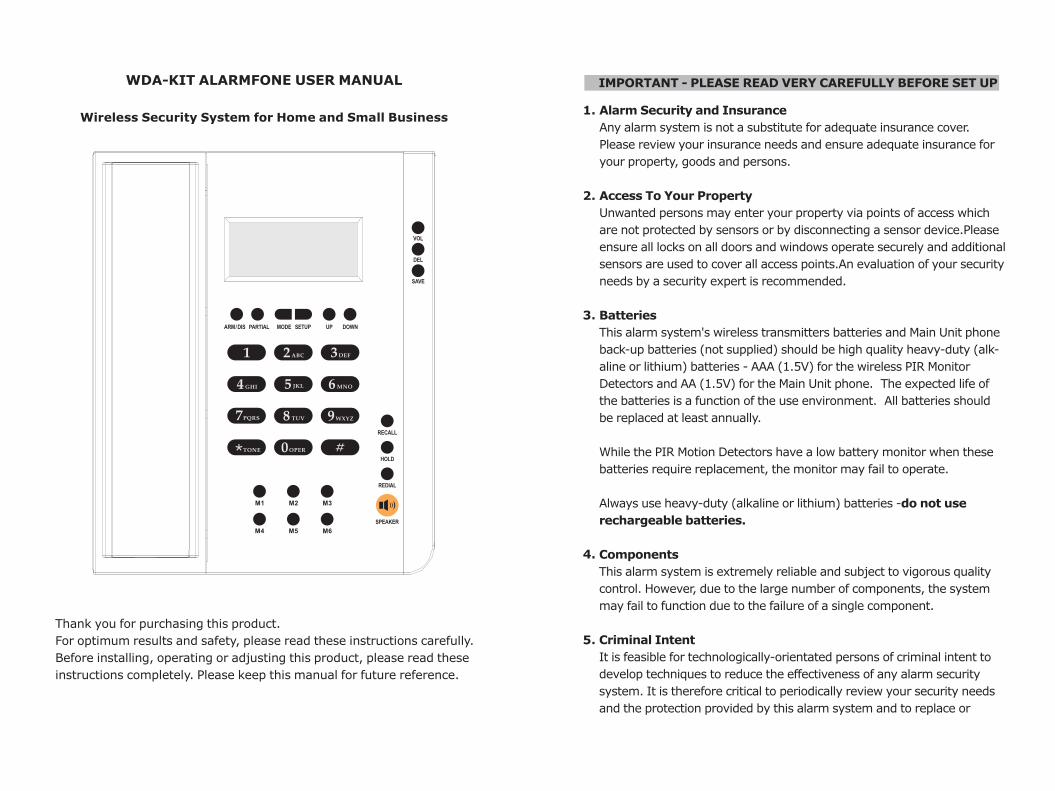
WDA-KIT ALARMFONE USER MANUAL
Wireless Security System for Home and Small Business
Thank you for purchasing this product.
For optimum results and safety, please read these instructions carefully.
Before installing, operating or adjusting this product, please read these
instructions completely. Please keep this manual for future reference.
Update the system if it does not provide the necessary protection that
you require.
Insufficient Response
Responsiveness by third parties is outside the control of the alarm
system. Any emergency event reported by the alarm system requires
a response by third parties (eg, ambulance, patrol car, police, etc). The
response may not happen in time to protect property, goods or persons.
Adequate insurance cover for property, goods and persons is regarded
as mandatory.
Inadequate Service Testing
Adequate maintenance,service and testing is also regarded as mandato-
ry; regular testing can identify problems of system failure.The complete
system should be tested at least monthly and immediately after any
major property event (eg, accident, break-in, fire, storm and tempest,
earthquake, building renovation or modification, etc). Refer to the "User
Guide" index for testing instructions.
PIR Motion Detectors and False Alarms
PIR motion detectors can only detect movement within the limited areas
and cannot distinguish between individuals and animals. They cannot
detect movement behind partitions (ie, doors, windows, walls, etc); they
operate by detecting changes in temperature and, therefore, when the
temperature rises to near or above body temperature (or there are other
sources of heat(such as barbeques, heaters, direct sunlight, etc)they can
generate false alarms.Open windows resulting in draughts and indoor p-
lant movement, insects and/or cobwebs in/or detectors and pets not be-
ing restricted to areas that are not armed can also generate false alarms.
To reduce the risk of false alarms it is recommended that before turning
on/arming your system that you:
¡ Lock all windows and doors;
¡ Restrict animals to rooms that are not protected by sensors;
¡ Inspect all sensors to ensure they are clear of obstructions and insects
or cobwebs; and
¡ Ensure everyone on the property knows how to cancel false alarms.
6.
7.
8.
Power Failure
Power failure or interruption resulting in voltage fluctuations can damage
electronic systems. After any power fluctuation immediately conduct a
system test to ensure the system is fully operational. Refer to the 'User
Guide' index for testing instructions.
Security System Users
All users must be familiar with how the alarm system works and how to
react to alarms (including how to cancel a false alarm).
Telephone Line Reliability
The alarm system relies on transmission via the telephone line.Telephone
lines may be busy temporarily out of service, or interfered with.
Wireless Devices
Sensor signals may not always reach the Main Unit to initiate an alarm
due to accidental radio frequency interference or jamming.
M aintenance/Service
To comply with the relevant Australian Standard and the requirements
of Police for their response to an alarm event and insurance companies
(to qualify for security - monitoring house and contents insurance
discounts) your security system must be tested annually by a licensed
expert. Pleasering the Help Desk to arrange your annual system
test.
9.
10.
11.
12.
13.
FEATURES...................................................................................................
Pack Contents...............................................................................................
Equipment Summary.....................................................................................
QUICK SETUP GUIDE..................................................................................
Main Unit Setup.............................................................................................
Door Gap Sensor Setup..................................................................................
Passive Infrared Sensor (PIR) Setup................................................................
Quick Tabletop Test.........................................................................................
INSTALLATION GUIDE................................................................................
Main Unit Installation.......................................................................................
Door Gap Sensor Installation...........................................................................
PIR Sensor Installation....................................................................................
Avoiding False Alarms.....................................................................................
OPERATION GUIDE.....................................................................................
Telephone......................................................................................................
TELEPHONE SETTINGS...............................................................................
Phone Book....................................................................................................
Brightness......................................................................................................
Time and Date Settings...................................................................................
Incoming Calls................................................................................................
Outgoing Calls................................................................................................
ALARM SETTINGS........................................................................................
Change Password............................................................................................
Base Numbers.................................................................................................
Self Monitoring Numbers..................................................................................
Deleting Base Numbers...................................................................................
Deleting Self Monitoring Numbers....................................................................
Delay Time.....................................................................................................
PIR Low Power................................................................................................
Partial Alarm Function.....................................................................................
Siren Time.....................................................................................................
Status to Base................................................................................................
Clear Zone.....................................................................................................
ARMING AND DISARMING.........................................................................
ALARM TYPES..............................................................................................
MONITORING..............................................................................................
Back to Base Monitoring..................................................................................
Self Monitoring...............................................................................................
REGISTERING NEW DEVICES.....................................................................
MAINTENANCE / SERVICE..........................................................................
ZONES...........................................................................................................
TABLE OF CONTENTS
Page 1
Page 1
Page 2
Page 4
Page 4
Page 8
Page 9
Page 10
Page 13
Page 13
Page 14
Page 16
Page 19
Page 20
Page 20
Page 21
Page 21
Page 22
Page 23
Page 24
Page 25
Page 26
Page 26
Page 28
Page 31
Page 33
Page 35
Page 37
Page 39
Page 40
Page 42
Page 43
Page 44
Page 46
Page 49
Page 50
Page 50
Page 51
Page 52
Page 64
Page 65
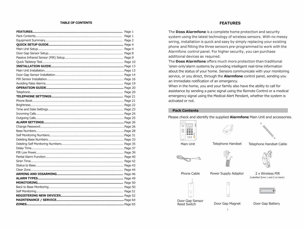
Power Supply Adaptor
FEATURES
The Doss Alarmfone is a complete home protection and security
system using the latest technology of wireless sensors. With no messy
wiring, installation is quick and easy by simply replacing your existing
phone and fitting the three sensors pre-programmed to work with the
Alarmfone control panel. For higher security, you can purchase
additional devices as required.
The Doss Alarmfone offers much more protection than traditional
'siren-only'alarm systems by providing intelligent real-time information
about the status of your home. Sensors communicate with your monitoring
service, or you direct, through the Alarmfone control panel, sending you
an immediate notification of an emergency.
When in the home, you and your family also have the ability to call for
assistance by sending a panic signal using the Remote Control or a medical
emergency signal using the Medical Alert Pendant, whether the system is
activated or not.
Pack Contents
Please check and identify the supplied Alarmfone Main Unit and accessories.
Main Unit Telephone Handset Cable
Phone Cable 2 x Wireless PIR (Labelled Zone 1 and 2 on back)
Door Gap SensorReed Switch Door Gap Magnet Door Gap Battery
Telephone Handset
1
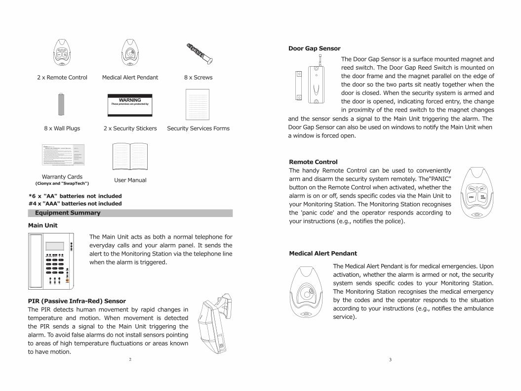
The Door Gap Sensor is a surface mounted magnet and
reed switch. The Door Gap Reed Switch is mounted on
the door frame and the magnet parallel on the edge of
the door so the two parts sit neatly together when the
door is closed. When the security system is armed and
the door is opened, indicating forced entry, the change
in proximity of the reed switch to the magnet changes
and the sensor sends a signal to the Main Unit triggering the alarm. The
Door Gap Sensor can also be used on windows to notify the Main Unit when
The handy Remote Control can be used to conveniently
arm and disarm the security system remotely. The"PANIC"
button on the Remote Control when activated, whether the
alarm is on or off, sends specific codes via the Main Unit to
your Monitoring Station. The Monitoring Station recognises
the 'panic code' and the operator responds according to
Remote Control
your instructions (e.g., notifies the police).
The Medical Alert Pendant is for medical emergencies. Upon
activation, whether the alarm is armed or not, the security
system sends specific codes to your Monitoring Station.
The Monitoring Station recognises the medical emergency
by the codes and the operator responds to the situation
according to your instructions (e.g., notifies the ambulance
Medical Alert Pendant
service).
Door Gap Sensor
a window is forced open.
WARNINGThese premises are protected by
NZ
2 x Remote Control Medical Alert Pendant 8 x Screws
8 x Wall Plugs 2 x Security Stickers Security Services Forms
User ManualWarranty Cards
(Cionyx and "SwapTech")
Equipment Summary
Main Unit
The Main Unit acts as both a normal telephone for
everyday calls and your alarm panel. It sends the
alert to the Monitoring Station via the telephone line
The PIR detects human movement by rapid changes in
temperature and motion. When movement is detected
the PIR sends a signal to the Main Unit triggering the
alarm. To avoid false alarms do not install sensors pointing
to areas of high temperature fluctuations or areas known
when the alarm is triggered.
PIR (Passive Infra-Red) Sensor
to have motion.2 3
*6 x AA batteries not included
#4 x "AAA" batteries not included
" "
REPAIR AND WARRANTY Limited Warranty
CIONYX PTY. LTD.
Thank you for selecting a Cionyx value for money product.
Cionyx Pty Ltd warrants this Product free from defects in material and ship for one year from date of purchase.
Within this warranty period Cionyx Pty Ltd will repair or replace defective parts and / or accessories at no charge, provided
the Product is returned with proof of purchase (original invoice).
The buyer assumes all responsibility for proper selection, installation and maintenance. This warranty is invalid in any case
that the Product unit (body) is opened, modified or serviced by an unauthorized service firm.
Any replacement or repaired Product will be warranted from the moment of replacement or repair for the unused remainder
of the original warranty period or 90 days, whichever is the longer.
This warranty is void to the extent that failure of the Product results from modification, accident, abuse, misapplication or any
failure to observe instructions in the accompanying documentation (User's Manual) regarding proper unpacking, installation,
maintenance and/or service of the Product.
workman
Please refer and read to the enclosed 'SwapTech Replacement Guarantee' which ensures your satisfaction with this product. If you have any questions /Queries please ring our Help Desk any time at your convenience.
Please register your 'SwapTech' warranty immediately and receive 12 months free operational support by ringing the Help Desk now (Australia: 1300 736 963 /New Zealand: 0800 200 318 ) www.fortknoxsecure.com
SERIAL NO.:
ALARM ID NO.:
0800-604-560
0800-604-567
MONITORING STATION 1:
MONITORING STATION 2:
PLEASE CHANGE YOUR PASSWORD BEFORE USING THE UNIT
Copyright 2007 Cionyx Pty. Ltd.
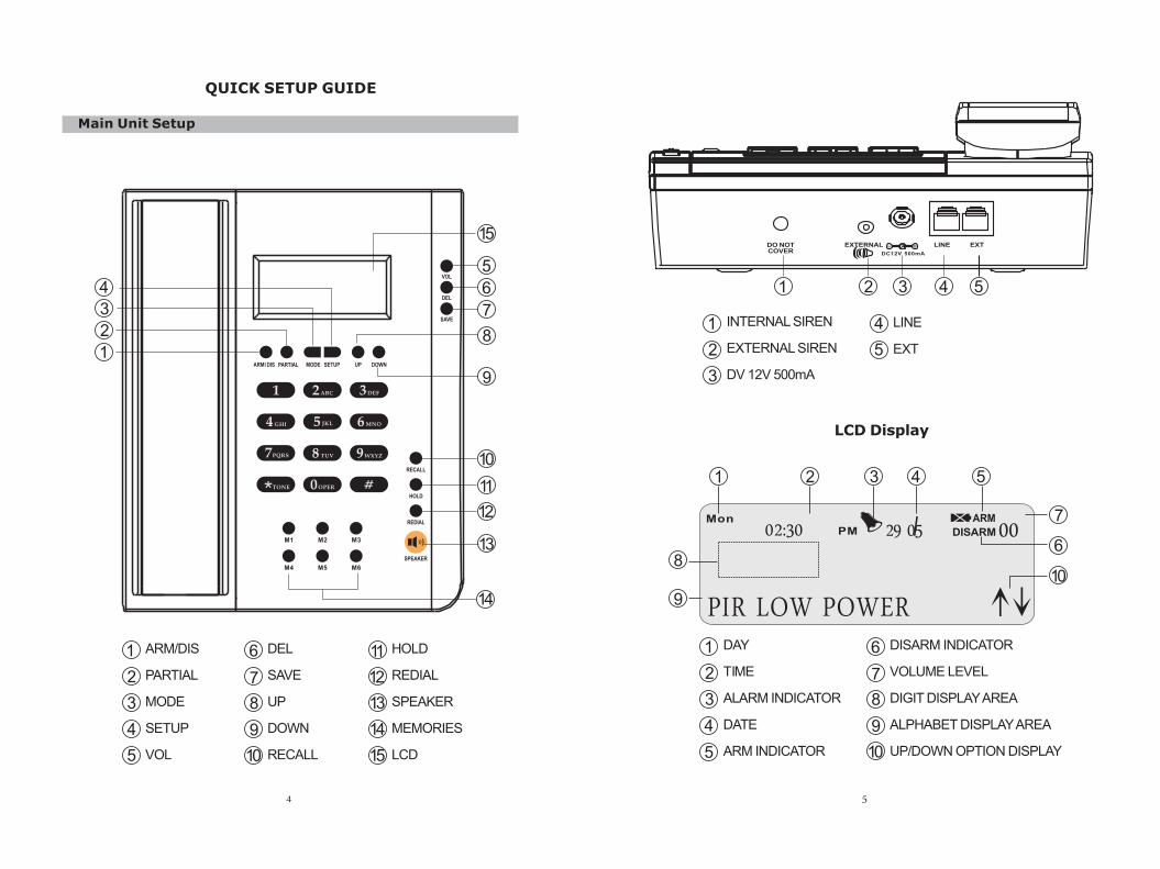
Main Unit Setup
1
2
3
4
5
6
7
8
9
10
11
12
13
14
15
DEL
SAVE
UP
DOWN
RECALL
HOLD
REDIAL
SPEAKER
MEMORIES
LCD
11
12
13
14
15
1
2
3
4
5
ARM/DIS
PARTIAL
MODE
SETUP
VOL
6
7
8
9
10
4
QUICK SETUP GUIDE
3
INTERNAL SIREN
EXTERNAL SIREN
DV 12V 500mA
LCD Display
29 05 00MonPM DISARM
ARM
PIR LOW POWER
5
1
2
3
4
DAY
TIME
ALARM INDICATOR
DATE
ARM INDICATOR
DISARM INDICATOR
VOLUME LEVEL
DIGIT DISPLAY AREA
ALPHABET DISPLAY AREA
UP/DOWN OPTION DISPLAY
6
7
8
9
10
1 2 3 4 5
6
7
810
9
5
02:30
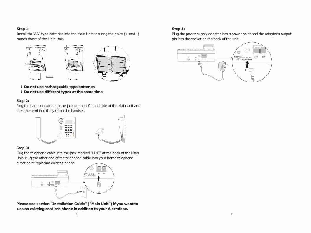
Step 4:
Plug the power supply adapter into a power point and the adaptor's output
pin into the socket on the back of the unit.
Step 1:
Install six "AA" type batteries into the Main Unit ensuring the poles (+ and -)
match those of the Main Unit.
¡
¡ Do not use different types at the same time
Do not use rechargeable type batteries
Step 2:
Plug the handset cable into the jack on the left hand side of the Main Unit and
the other end into the jack on the handset.
Step 3:
Plug the telephone cable into the jack marked "LINE" at the back of the Main
Unit. Plug the other end of the telephone cable into your home telephone
outlet point replacing existing phone.
EXTERNAL LINE EXT
EXTERNALDO NOTCOVER
LINE EXT
Please see section "Installation Guide" ("Main Unit") if you want to
use an existing cordless phone in addition to your Alarmfone.
6
EXTERNAL LINE EXTEXTERNALDO NOT
COVERLINE EXT
7
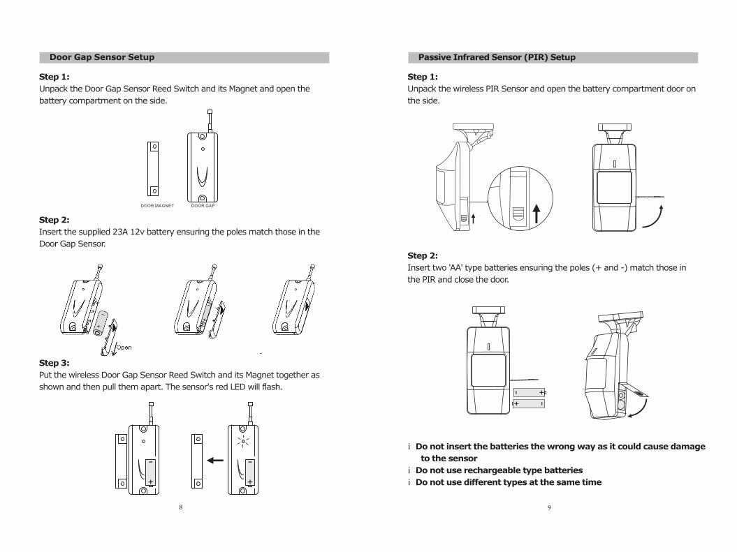
Door Gap Sensor Setup
Step 1:
Unpack the Door Gap Sensor Reed Switch and its Magnet and open the
battery compartment on the side.
Step 2:
Insert the supplied 23A 12v battery ensuring the poles match those in the
Door Gap Sensor.
Step 3:
Put the wireless Door Gap Sensor Reed Switch and its Magnet together as
shown and then pull them apart. The sensor's red LED will flash.
DOOR MAGNET DOOR GAP
8
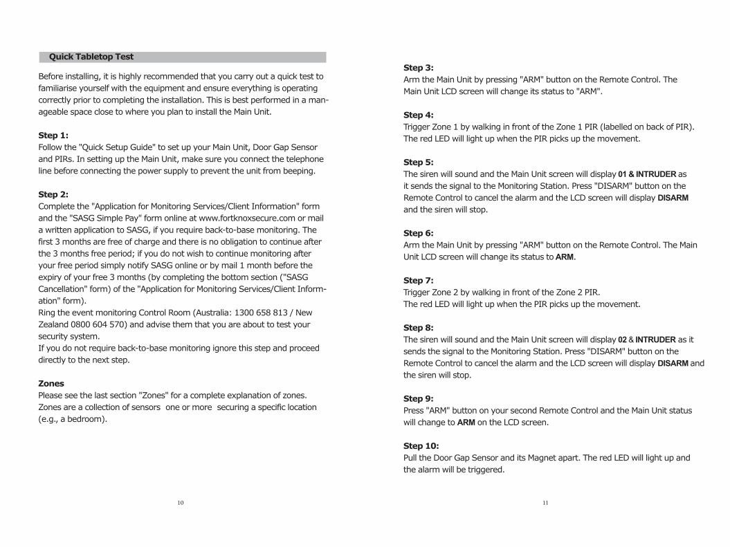
Passive Infrared Sensor (PIR) Setup
Step 1:
Unpack the wireless PIR Sensor and open the battery compartment door on
the side.
Step 2:
Insert two 'AA' type batteries ensuring the poles (+ and -) match those in
the PIR and close the door.
¡ Do not insert the batteries the wrong way as it could cause damage
to the sensor
¡ Do not use rechargeable type batteries
¡ Do not use different types at the same time
9
Quick Tabletop Test
Before installing, it is highly recommended that you carry out a quick test to
familiarise yourself with the equipment and ensure everything is operating
correctly prior to completing the installation. This is best performed in a man-
ageable space close to where you plan to install the Main Unit.
Step 1:
Follow the "Quick Setup Guide" to set up your Main Unit, Door Gap Sensor
and PIRs. In setting up the Main Unit, make sure you connect the telephone
line before connecting the power supply to prevent the unit from beeping.
Step 2:
Complete the "Application for Monitoring Services/Client Information" form
and the "SASG Simple Pay" form online at www.fortknoxsecure.com or mail
a written application to SASG, if you require back-to-base monitoring. The
first 3 months are free of charge and there is no obligation to continue after
the 3 months free period; if you do not wish to continue monitoring after
your free period simply notify SASG online or by mail 1 month before the
expiry of your free 3 months (by completing the bottom section ("SASG
Cancellation" form) of the "Application for Monitoring Services/Client Inform-
ation" form).
Ring the event monitoring Control Room (Australia: 1300 658 813 / New
Zealand 0800 604 570) and advise them that you are about to test your
security system.
If you do not require back-to-base monitoring ignore this step and proceed
directly to the next step.
Zones
Please see the last section "Zones" for a complete explanation of zones.
Zones are a collection of sensors one or more securing a specific location
(e.g., a bedroom).
10
Step 3:
Arm the Main Unit by pressing "ARM" button on the Remote Control. The
Main Unit LCD screen will change its status to "ARM".
Step 4:
Trigger Zone 1 by walking in front of the Zone 1 PIR (labelled on back of PIR).
The red LED will light up when the PIR picks up the movement.
Step 5:
The siren will sound and the Main Unit screen will display 01 & INTRUDER as
it sends the signal to the Monitoring Station. Press "DISARM" button on the
Remote Control to cancel the alarm and the LCD screen will display DISARM
and the siren will stop.
Step 6:
Arm the Main Unit by pressing "ARM" button on the Remote Control. The Main
Unit LCD screen will change its status to ARM.
Step 7:
Trigger Zone 2 by walking in front of the Zone 2 PIR.
The red LED will light up when the PIR picks up the movement.
Step 8:
The siren will sound and the Main Unit screen will display 02 & INTRUDER as it
sends the signal to the Monitoring Station. Press "DISARM" button on the
Remote Control to cancel the alarm and the LCD screen will display DISARM and
the siren will stop.
Step 9:
Press "ARM" button on your second Remote Control and the Main Unit status
will change to ARM on the LCD screen.
Step 10:
Pull the Door Gap Sensor and its Magnet apart. The red LED will light up and
the alarm will be triggered.
11
Step 11:
The siren will sound and the Main Unit will display 06 & DOOR as it sends a
signal to the Monitoring Station. Press "DISARM" button on the Remote
Control to cancel the alarm and the LCD screen will display DISARM.
Step 12:
While the Main Unit is disarmed, press the button on your Medical Alert
Pendant. The Main Unit's LCD screen will display 08 &EMERGENCY while it
sends a medical help signal to the Monitoring Station. Cancel the signal by
pressing "DISARM" button on your Remote Control. The siren will not go off
in the case of medical emergency.
Step 13:
Press "PANIC" button on your Remote Control. The Main Unit's LCD screen
will display 00 & PANIC. Press "DISARM" to cancel. The siren will NOT sound
when the "PANIC" button is pressed.
Step 14:
Disconnect the phone line. The Main Unit will start beeping. Reconnect the
phone cable and the beeping will stop.
Step 15:
Arm the Main Unit by pressing "ARM" on the Remote Control.
Step 16:
Disconnect the phone cable and the siren will go off 5 seconds later. Press
"DISARM" on the Remote Control and the siren will stop.
Step 17:
While the Main Unit is disarmed, open the battery compartment of either PIR
Zone 1 or 2. The Main Unit's LCD screen will display TAMPER and the siren
will sound. Press "DISARM" button on the Remote Control to cancel the alarm.
12 13
INSTALLATION GUIDE
Main Unit Installation
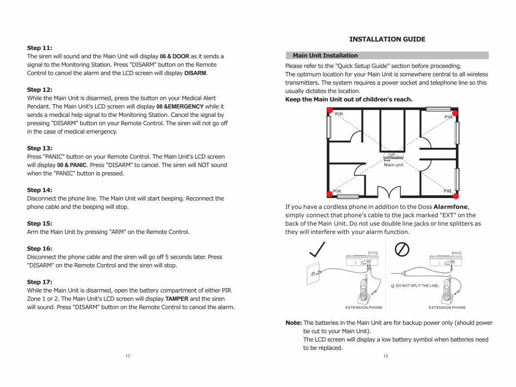
Please refer to the "Quick Setup Guide" section before proceeding.
The optimum location for your Main Unit is somewhere central to all wireless
transmitters. The system requires a power socket and telephone line so this
usually dictates the location.
Keep the Main Unit out of children's reach.
If you have a cordless phone in addition to the Doss Alarmfone,
simply connect that phone's cable to the jack marked "EXT" on the
back of the Main Unit. Do not use double line jacks or line splitters as
they will interfere with your alarm function.
Note: The batteries in the Main Unit are for backup power only (should power
be cut to your Main Unit).
The LCD screen will display a low battery symbol when batteries need
to be replaced.
PIRPIR
PIRPIR
Main unit
EXTERNALSIREN
OUTPUT
EXTENSION PHONE
EXTERNALSIREN
OUTPUT
DO NOT SPLIT THE LINE£
EXTENSION PHONE
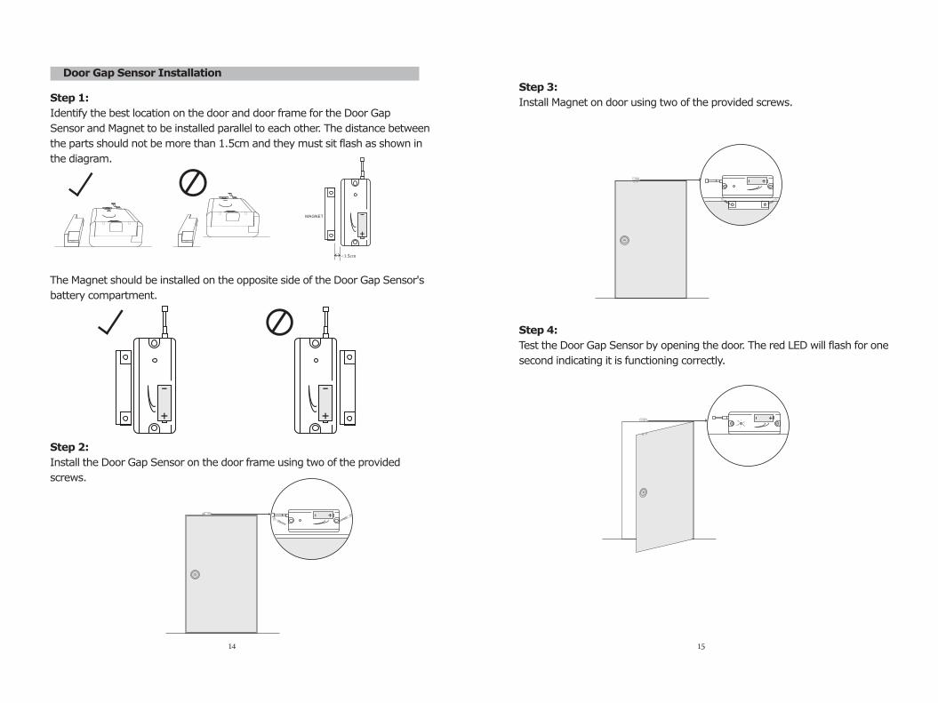
Door Gap Sensor Installation
Step 1:
Identify the best location on the door and door frame for the Door Gap
Sensor and Magnet to be installed parallel to each other. The distance between
the parts should not be more than 1.5cm and they must sit flash as shown in
the diagram.
The Magnet should be installed on the opposite side of the Door Gap Sensor's
battery compartment.
Step 2:
Install the Door Gap Sensor on the door frame using two of the provided
screws.
MAGNET
<1.5cm
14
Step 3:
Install Magnet on door using two of the provided screws.
Step 4:
Test the Door Gap Sensor by opening the door. The red LED will flash for one
second indicating it is functioning correctly.
15
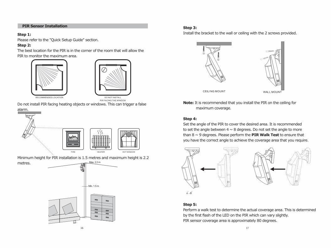
PIR Sensor Installation
Step 1:
Please refer to the "Quick Setup Guide" section.
Step 2:
The best location for the PIR is in the corner of the room that will allow the
PIR to monitor the maximum area.
Do not install PIR facing heating objects or windows. This can trigger a false
alarm.
Minimum height for PIR installation is 1.5 metres and maximum height is 2.2
metres.
DO NOT INSTALL
PIR FACING THE WINDOW
RECOMMENDED LOCATION
FIRE HOT WINDOWHEATER
Min. 1.5 m
16
Step 3:
Install the bracket to the wall or ceiling with the 2 screws provided.
Note: It is recommended that you install the PIR on the ceiling for
maximum coverage.
Step 4:
Set the angle of the PIR to cover the desired area. It is recommended
to set the angle between 4 ~ 8 degrees. Do not set the angle to more
than 8 ~ 9 degrees. Please perform the PIR Walk Test to ensure that
you have the correct angle to achieve the coverage area that you require.
Step 5:
Perform a walk test to determine the actual coverage area. This is determined
by the first flash of the LED on the PIR which can vary slightly.
PIR sensor coverage area is approximately 80 degrees.
CEILI NG MOUNT WALL MOUNT
17
Max. 2.2 m
o4 ~8
o
Note: It is recommended that you read carefully the last section "Zones" and
draw a rough floor plan of your property marking all
intended protected zones and the location of each sensor
before installing you Doss Alarmfone.
Do not install PIR in a location where there is known to be movement.
¡ Do not install PIR aiming at the window.
¡ Do not install PIR aiming at heating units.
¡ Do not install PIR near the heating vent, air-conditioning, fire place or
sunlight.
¡ Install the PIR in a permanent position. Do not place it on a shelf.
¡ Install the PIR within 30 metres of the Main Unit even though the PIR
sensor range is 100 metres in an open area.
¡ Pet movement will also trigger the PIR Sensor so consider other methods
of detection to areas where pets/animals have no access during times
when the alarm system is armed. (e.g., use additional Door Gap Sensors
on doors and windows to secure areas where there is likely to be movem-
ent when the system is armed).
Replacing PIR Batteries
Please ring the event monitoring Control Room whenever you are changing
PIR batteries, as an event signal ("TAMPER") will be sent to the Control Room
-a false alarm- which you do not want the Control Room to act upon.
Changing Your Password
You must change the default password when you set up your alarm system
for the first time.
"See Alarm Settings - Change Password"
¡
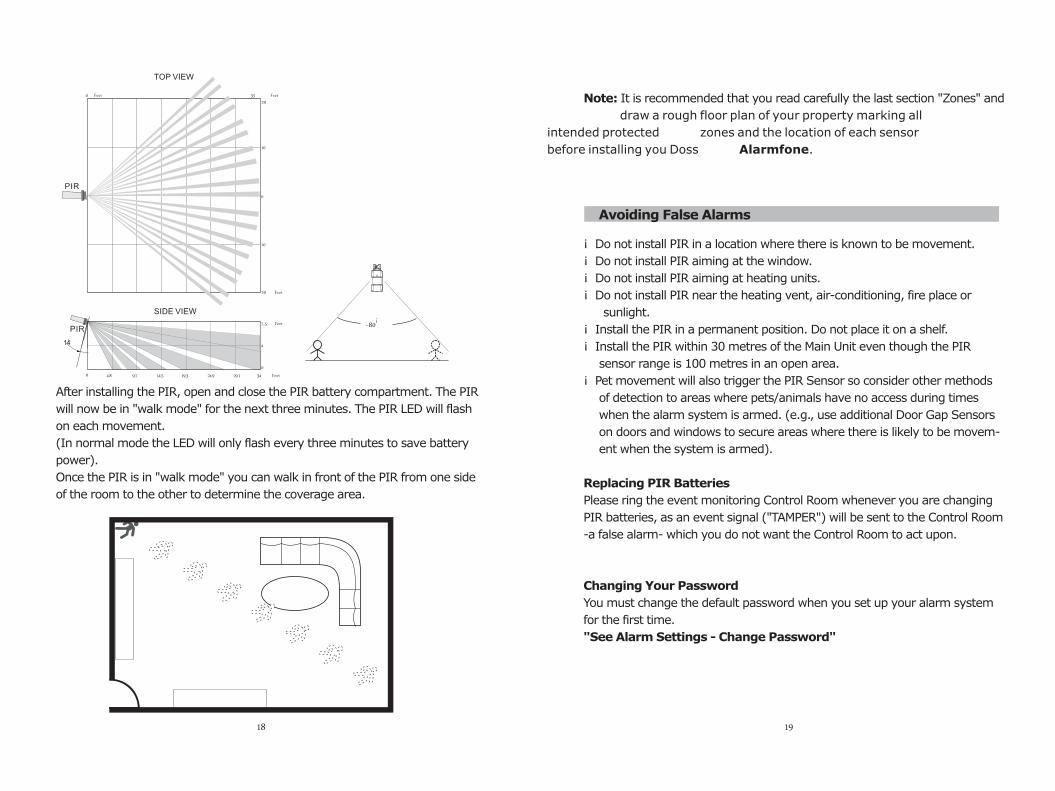
After installing the PIR, open and close the PIR battery compartment. The PIR
will now be in "walk mode" for the next three minutes. The PIR LED will flash
on each movement.
(In normal mode the LED will only flash every three minutes to save battery
power).
Once the PIR is in "walk mode" you can walk in front of the PIR from one side
of the room to the other to determine the coverage area.
0 35 20
TOP VIEW
10
20
10
0
PIR
0
7.5
¡14
4.8
SIDE VIEW
4
0
9.7 14.5 19.3 24.9 29.1 34 Feet
PIR
¡~80
18
Avoiding False Alarms
19
Feet
Feet Feet
Feet
OPERATION GUIDE
Dialling:
Pick up handset or press the "SPEAKER" button for dial tone. Dial the number.
Hands Free:
Press the "SPEAKER" button and then dial the number. To use the speaker
function, the power supply must be connected. To hang up the call press the
"SPEAKER" button again.
Receive Call:
Pick up the handset when the phone rings and you will be connected to the
calling party. Put the handset back on the cradle when you have finished the
call.
Volume:
Press "VOL" button to set the desired volume.
Redial:
Pick up the handset and press the "REDIAL" button to call the last number
dialled.
Hold:
While on a call, press the "HOLD" button to put the other party on temporary
hold. Press the "HOLD" button again to return to the conversation.
Recall:
If you have "call waiting" through your phone service provider you can use
the "RECALL" button to put the call on hold while you answer the new call.
When you hear a ring tone indicating another call, press the "RECALL" button
and then "2" to be connected to party B while party A is put on hold. When
you have finished with party B, press the "RECALL" button and then "1" to
return to party A. (This key combination may change depending on your phone
service provider).
Call number display:
The Doss Alarmfone will automatically display the incoming call
number on the LCD screen.
Telephone
20
TELEPHONE SETTINGS
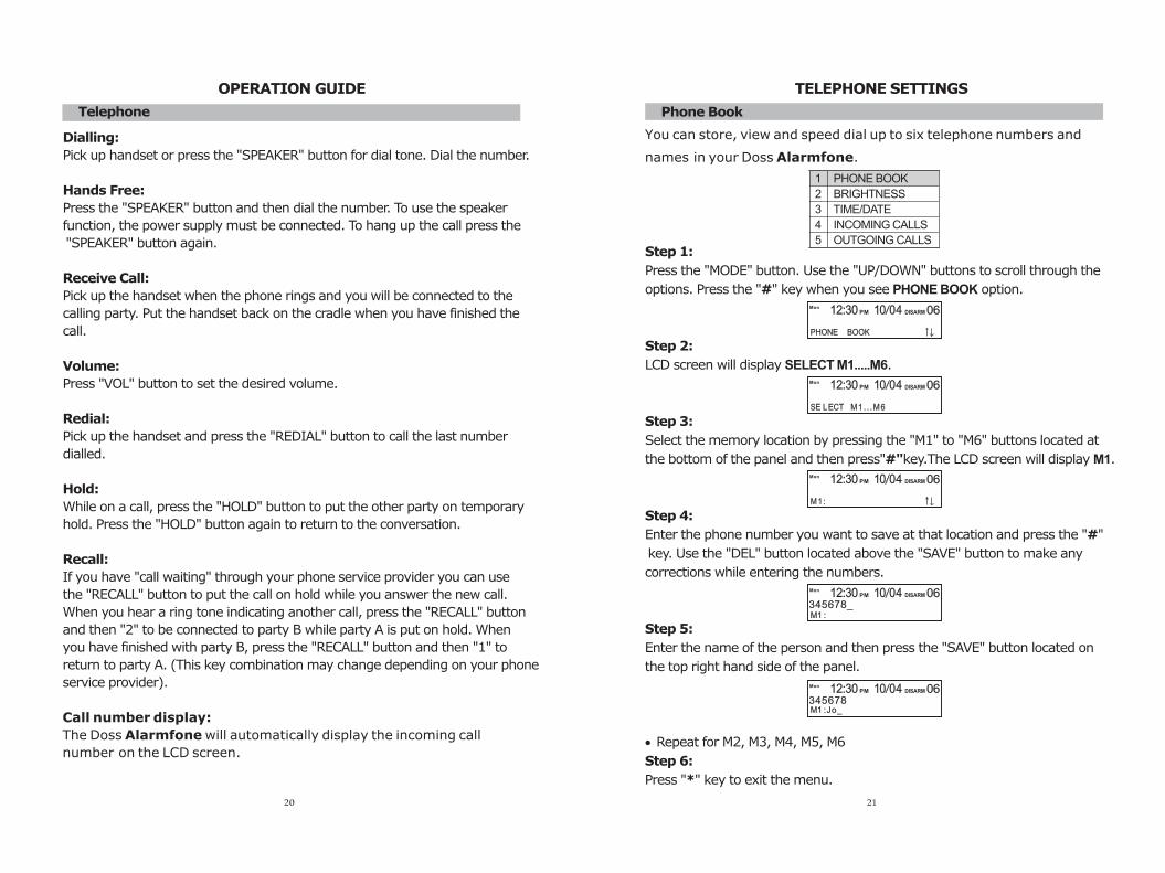
Phone Book
You can store, view and speed dial up to six telephone numbers and
names in your Doss Alarmfone.
Step 1:
Press the "MODE" button. Use the "UP/DOWN" buttons to scroll through the
options. Press the "#" key when you see PHONE BOOK option.
Step 2:
LCD screen will display SELECT M1.....M6.
Step 3:
Select the memory location by pressing the "M1" to "M6" buttons located at
the bottom of the panel and then press"#"key.The LCD screen will display M1.
Step 4:
Enter the phone number you want to save at that location and press the "#"
key. Use the "DEL" button located above the "SAVE" button to make any
corrections while entering the numbers.
Step 5:
Enter the name of the person and then press the "SAVE" button located on
the top right hand side of the panel.
· Repeat for M2, M3, M4, M5, M6
Step 6:
Press "*" key to exit the menu.
1 PHONE BOOK
2 BRIGHTNESS
3 TIME/DATE
4 INCOMING CALLS
5 OUTGOING CALLS
MonPM DISARM12:30 10 04 06
PHONE BOOK
MonPM DISARM12:30 10 04 06
SE LECT M1 . . .M6
MonPM DISARM12:30 10 04 06
M1:
M1 :
MonPM DISARM12:30 10 04 06
345678_
M1 :Jo_
MonPM DISARM12:30 10 04 06
345678
21
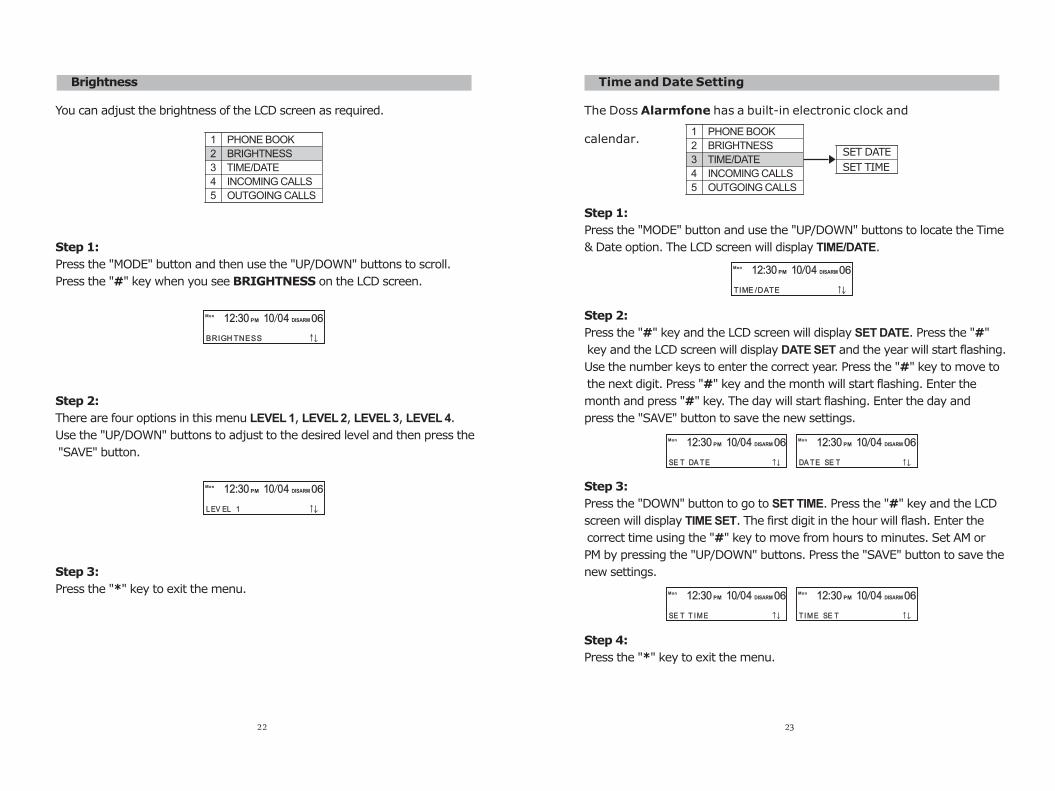
Time and Date Setting
The Doss Alarmfone has a built-in electronic clock and
calendar.
Step 1:
Press the "MODE" button and use the "UP/DOWN" buttons to locate the Time
& Date option. The LCD screen will display TIME/DATE.
Step 2:
Press the "#" key and the LCD screen will display SET DATE. Press the "#"
key and the LCD screen will display DATE SET and the year will start flashing.
Use the number keys to enter the correct year. Press the "#" key to move to
the next digit. Press "#" key and the month will start flashing. Enter the
month and press "#" key. The day will start flashing. Enter the day and
press the "SAVE" button to save the new settings.
Step 3:
Press the "DOWN" button to go to SET TIME. Press the "#" key and the LCD
screen will display TIME SET. The first digit in the hour will flash. Enter the
correct time using the "#" key to move from hours to minutes. Set AM or
PM by pressing the "UP/DOWN" buttons. Press the "SAVE" button to save the
new settings.
Step 4:
Press the "*" key to exit the menu.
Brightness
You can adjust the brightness of the LCD screen as required.
Step 1:
Press the "MODE" button and then use the "UP/DOWN" buttons to scroll.
Press the "#" key when you see BRIGHTNESS on the LCD screen.
Step 2:
There are four options in this menu LEVEL 1, LEVEL 2, LEVEL 3, LEVEL 4.
Use the "UP/DOWN" buttons to adjust to the desired level and then press the
"SAVE" button.
Step 3:
Press the "*" key to exit the menu.
1 PHONE BOOK
2 BRIGHTNESS
3 TIME/DATE
4 INCOMING CALLS
5 OUTGOING CALLS
BRIGH TNESS
MonPM DISARM12:30 10 04 06
MonPM DISARM12:30 10 04 06
LEV EL 1
22
1 PHONE BOOK
2 BRIGHTNESS
3 TIME/DATE
4 INCOMING CALLS
5 OUTGOING CALLS
SET DATE
SET TIME
TIME /DATE
MonPM DISARM12:30 10 04 06
MonPM DISARM12:30 10 04 06
SE T DA TE
MonPM DISARM12:30 10 04 06
DA TE SE T
MonPM DISARM12:30 10 04 06
SE T T IME
MonPM DISARM12:30 10 04 06
T IME SE T
23
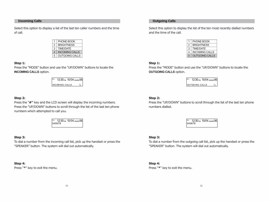
Incoming Calls
Select this option to display a list of the last ten caller numbers and the time
of call.
Step 1:
Press the "MODE" button and use the "UP/DOWN" buttons to locate the
INCOMING CALLS option.
Step 2:
Press the "#" key and the LCD screen will display the incoming numbers.
Press the "UP/DOWN" buttons to scroll through the list of the last ten phone
numbers which attempted to call you.
Step 3:
To dial a number from the incoming call list, pick up the handset or press the
"SPEAKER" button. The system will dial out automatically.
Step 4:
Press "*" key to exit the menu.
1 PHONE BOOK
2 BRIGHTNESS
3 TIME/DATE
4 INCOMING CALLS
5 OUTGOING CALLS
INCOM ING CALLS
MonPM DISARM12:30 10 04 06
MonPM DISARM12:30 10 04 06
345678
24
Outgoing Calls
Select this option to display the list of the ten most recently dialled numbers
and the time of the call.
Step 1:
Press the "MODE" button and use the "UP/DOWN" buttons to locate the
OUTGOING CALLS option.
Step 2:
Press the "UP/DOWN" buttons to scroll through the list of the last ten phone
numbers dialled.
Step 3:
To dial a number from the outgoing call list, pick up the handset or press the
"SPEAKER" button. The system will dial out automatically.
Step 4:
Press "*" key to exit the menu.
1 PHONE BOOK
2 BRIGHTNESS
3 TIME/DATE
4 INCOMING CALLS
5 OUTGOING CALLS
OU TGO ING CALLS
MonPM DISARM12:30 10 04 06
MonPM DISARM12:30 10 04 06
345678
25
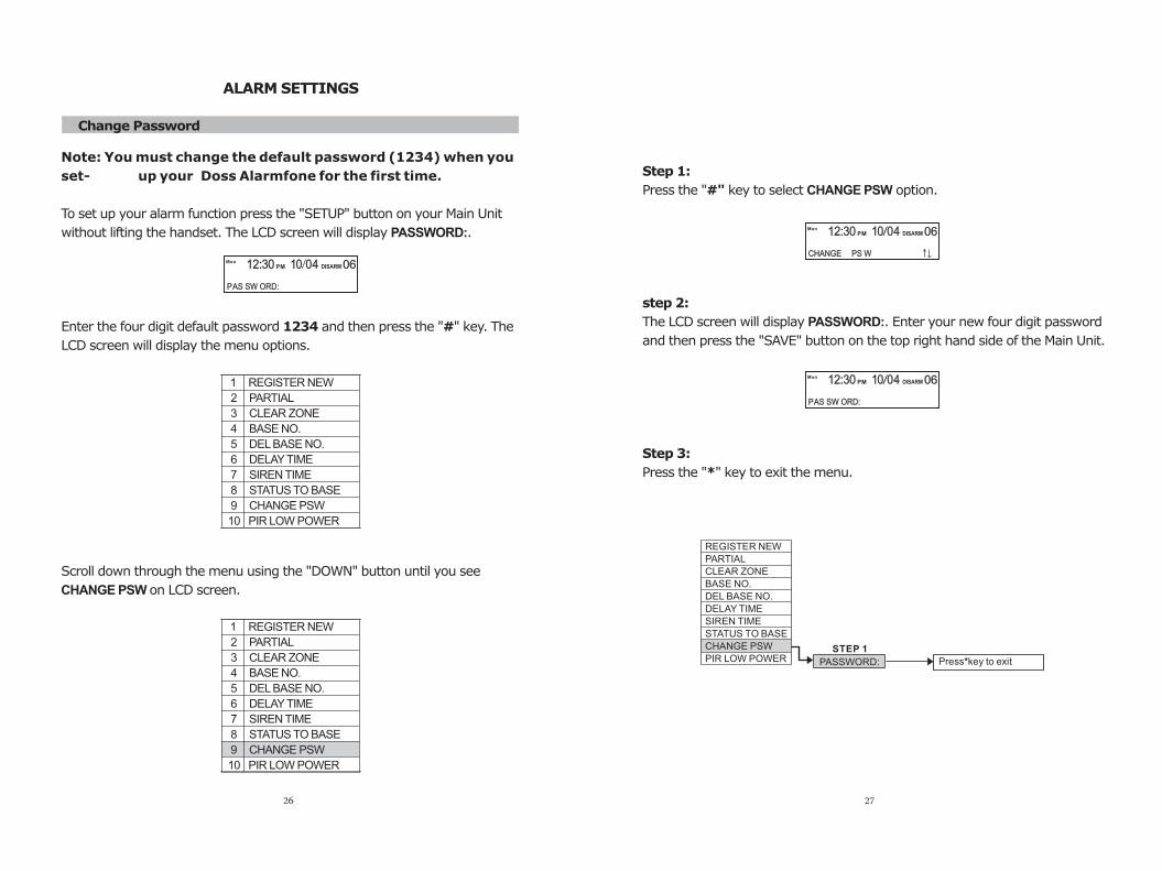
ALARM SETTINGS
Change Password
Note: You must change the default password (1234) when you
set- up your Doss Alarmfone for the first time.
To set up your alarm function press the "SETUP" button on your Main Unit
without lifting the handset. The LCD screen will display PASSWORD:.
Enter the four digit default password 1234 and then press the "#" key. The
LCD screen will display the menu options.
Scroll down through the menu using the "DOWN" button until you see
CHANGE PSW on LCD screen.
1 REGISTER NEW
2 PARTIAL
3 CLEAR ZONE
4 BASE NO.
5 DEL BASE NO.
6 DELAY TIME
7 SIREN TIME
8 STATUS TO BASE
9 CHANGE PSW
10 PIR LOW POWER
1 REGISTER NEW
2 PARTIAL
3 CLEAR ZONE
4 BASE NO.
5 DEL BASE NO.
6 DELAY TIME
7 SIREN TIME
8 STATUS TO BASE
9 CHANGE PSW
10 PIR LOW POWER
MonPM DISARM12:30 10 04 06
PAS SW ORD:
26
Step 1:
Press the "#" key to select CHANGE PSW option.
step 2:
The LCD screen will display PASSWORD:. Enter your new four digit password
and then press the "SAVE" button on the top right hand side of the Main Unit.
Step 3:
Press the "*" key to exit the menu.
MonPM DISARM12:30 10 04 06
CHANGE PS W
MonPM DISARM12:30 10 04 06
PAS SW ORD:
PASSWORD:
REGISTER NEW
PARTIAL
CLEAR ZONE
BASE NO.
DEL BASE NO.
DELAY TIME
SIREN TIME
STATUS TO BASE
CHANGE PSW
PIR LOW POWERSTEP 1
Press*key to exit
27
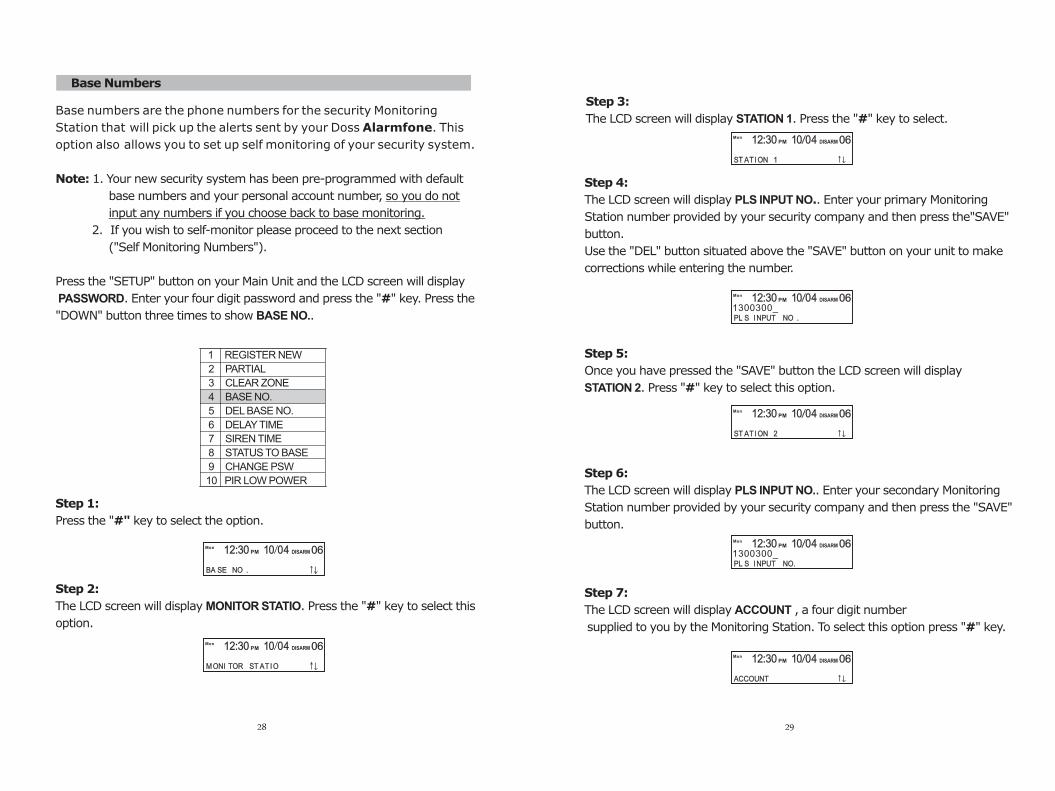
Step 4:
The LCD screen will display PLS INPUT NO.. Enter your primary Monitoring
Station number provided by your security company and then press the"SAVE"
button.
Use the "DEL" button situated above the "SAVE" button on your unit to make
corrections while entering the number.
Step 5:
Once you have pressed the "SAVE" button the LCD screen will display
STATION 2. Press "#" key to select this option.
Step 6:
The LCD screen will display PLS INPUT NO.. Enter your secondary Monitoring
Station number provided by your security company and then press the "SAVE"
button.
Step 7:
The LCD screen will display ACCOUNT , a four digit number
supplied to you by the Monitoring Station. To select this option press "#" key.
Base Numbers
Base numbers are the phone numbers for the security Monitoring
Station that will pick up the alerts sent by your Doss Alarmfone. This
option also allows you to set up self monitoring of your security system.
Note: 1. Your new security system has been pre-programmed with default
base numbers and your personal account number, so you do not
input any numbers if you choose back to base monitoring.
2. If you wish to self-monitor please proceed to the next section
("Self Monitoring Numbers").
Press the "SETUP" button on your Main Unit and the LCD screen will display
PASSWORD. Enter your four digit password and press the "#" key. Press the
"DOWN" button three times to show BASE NO..
Step 1:
Press the "#" key to select the option.
Step 2:
The LCD screen will display MONITOR STATIO. Press the "#" key to select this
option.
1 REGISTER NEW
2 PARTIAL
3 CLEAR ZONE
4 BASE NO.
5 DEL BASE NO.
6 DELAY TIME
7 SIREN TIME
8 STATUS TO BASE
9 CHANGE PSW
10 PIR LOW POWER
MonPM DISARM12:30 10 04 06
BA SE NO .
MonPM DISARM12:30 10 04 06
MONI TOR ST AT IO
28 29
MonPM DISARM12:30 10 04 06
ST ATION 1
MonPM DISARM12:30 10 04 06
ACCOUNT
MonPM DISARM12:30 10 04 06
ST ATION 2
MonPM DISARM12:30 10 04 06
PL S INPUT NO .1300300_
MonPM DISARM12:30 10 04 06
PL S INPUT NO.1300300_
Step 3:
The LCD screen will display STATION 1. Press the "#" key to select.
30
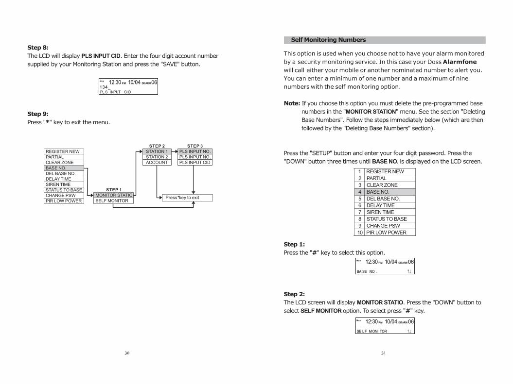
Step 8:
The LCD will display PLS INPUT CID. Enter the four digit account number
supplied by your Monitoring Station and press the "SAVE" button.
Step 9:
Press "*" key to exit the menu.
MonPM DISARM12:30 10 04 06
PL S INPUT CI D134_
STATION 1
STATION 2
ACCOUNT
REGISTER NEW
PARTIAL
CLEAR ZONE
BASE NO.
DEL BASE NO.
DELAY TIME
SIREN TIME
STATUS TO BASE
CHANGE PSW
PIR LOW POWER
MONITOR STATIO
SELF MONITOR
STEP 1
STEP 2
Press*key to exit
PLS INPUT NO .
PLS INPUT NO .
PLS INPUT CID
STEP 3
This option is used when you choose not to have your alarm monitored
by a security monitoring service. In this case your Doss Alarmfone
will call either your mobile or another nominated number to alert you.
You can enter a minimum of one number and a maximum of nine
numbers with the self monitoring option.
Note: If you choose this option you must delete the pre-programmed base
numbers in the "MONITOR STATION" menu. See the section "Deleting
Base Numbers". Follow the steps immediately below (which are then
followed by the "Deleting Base Numbers" section).
Press the "SETUP" button and enter your four digit password. Press the
"DOWN" button three times until BASE NO. is displayed on the LCD screen.
Step 1:
Press the "#" key to select this option.
Step 2:
The LCD screen will display MONITOR STATIO. Press the "DOWN" button to
select SELF MONITOR option. To select press "#" key.
Self Monitoring Numbers
1 REGISTER NEW
2 PARTIAL
3 CLEAR ZONE
4 BASE NO.
5 DEL BASE NO.
6 DELAY TIME
7 SIREN TIME
8 STATUS TO BASE
9 CHANGE PSW
10 PIR LOW POWER
MonPM DISARM12:30 10 04 06
BA SE NO .
MonPM DISARM12:30 10 04 06
SE LF MONI TOR
31
MonPM DISARM12:30 10 04 06
PL S INPUT NO .039812_
MonPM DISARM12:30 10 04 06
PL S INPUT NO .043000_
MonPM DISARM12:30 10 04 06
TEL 1
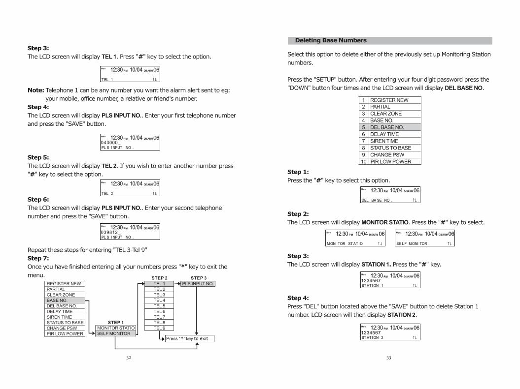
Step 3:
The LCD screen will display TEL 1. Press "#" key to select the option.
Note: Telephone 1 can be any number you want the alarm alert sent to eg:
your mobile, office number, a relative or friend's number.
Step 4:
The LCD screen will display PLS INPUT NO.. Enter your first telephone number
and press the "SAVE" button.
Step 5:
The LCD screen will display TEL 2. If you wish to enter another number press
"#" key to select the option.
Step 6:
The LCD screen will display PLS INPUT NO.. Enter your second telephone
number and press the "SAVE" button.
Repeat these steps for entering "TEL 3-Tel 9"
Step 7:
Once you have finished entering all your numbers press "*" key to exit the
menu.
MonPM DISARM12:30 10 04 06
TEL 2
MONITOR STATIO
SELF MONITOR
TEL 1
TEL 2
TEL 3
TEL 4
TEL 5
TEL 6
TEL 7
TEL 8
TEL 9
REGISTER NEW
PARTIAL
CLEAR ZONE
BASE NO.
DEL BASE NO.
DELAY TIME
SIREN TIME
STATUS TO BASE
CHANGE PSW
PIR LOW POWER
STEP 1
STEP 2
PLS INPUT NO .
STEP 3
Press "*" key to exit
32
Deleting Base Numbers
Select this option to delete either of the previously set up Monitoring Station
numbers.
Press the "SETUP" button. After entering your four digit password press the
"DOWN" button four times and the LCD screen will display DEL BASE NO.
Step 1:
Press the "#" key to select this option.
Step 2:
The LCD screen will display MONITOR STATIO. Press the "#" key to select.
Step 3:
The LCD screen will display STATION 1. Press the "#" key.
Step 4:
Press "DEL" button located above the "SAVE" button to delete Station 1
number. LCD screen will then display STATION 2.
1 REGISTER NEW
2 PARTIAL
3 CLEAR ZONE
4 BASE NO.
5 DEL BASE NO.
6 DELAY TIME
7 SIREN TIME
8 STATUS TO BASE
9 CHANGE PSW
10 PIR LOW POWER
1234567
MonPM DISARM12:30 10 04 06
ST ATION 1
MonPM DISARM12:30 10 04 06
ST ATION 21234567
MonPM DISARM12:30 10 04 06
DEL BA SE NO .
MonPM DISARM12:30 10 04 06
SE LF MONI TOR
MonPM DISARM12:30 10 04 06
MONI TOR ST AT IO
33

Step 5:
Press "DEL" button to delete Station 2 number. The LCD screen will display
Step 6:
Press "DEL" button to delete Account No.
Step 7:
Press the "*" key to exit the menu.
ACCOUNT.
MonPM DISARM12:30 10 04 06
ACCOUNT0002
STATION 1
STATION 2
ACCOUNT
REGISTER NEW
PARTIAL
CLEAR ZONE
BASE NO.
DEL BASE NO.
DELAY TIME
SIREN TIME
STATUS TO BASE
CHANGE PSW
PIR LOW POWER
STEP 2
MONITOR STATIO
SELF MONITOR
STEP 1
Press*key to exit
34
Deleting Self Monitoring Numbers
Use this option when you want to delete any of the numbers in the self
monitoring menu.
After entering your four digit password press the "DOWN" button four times
to display DEL BASE NO.
Step 1:
Press the "#" key to select the option.
Step 2:
The LCD screen will display MONITOR STATION. Press the "UP/DOWN" buttons
to select SELF MONITOR. Press the "#" key.
Step 3:
The LCD screen will display TEL 1. Press the "DEL" button to delete the first
telephone number.
Step 4:
The LCD screen will display TEL 2.
1 REGISTER NEW
2 PARTIAL
3 CLEAR ZONE
4 BASE NO.
5 DEL BASE NO.
6 DELAY TIME
7 SIREN TIME
8 STATUS TO BASE
9 CHANGE PSW
10 PIR LOW POWER
MonPM DISARM12:30 10 04 06
DEL BA SE NO .
MonPM DISARM12:30 10 04 06
SE LF MONI TOR
1234567
MonPM DISARM12:30 10 04 06
TEL 1
1234567
MonPM DISARM12:30 10 04 06
TEL 2 35
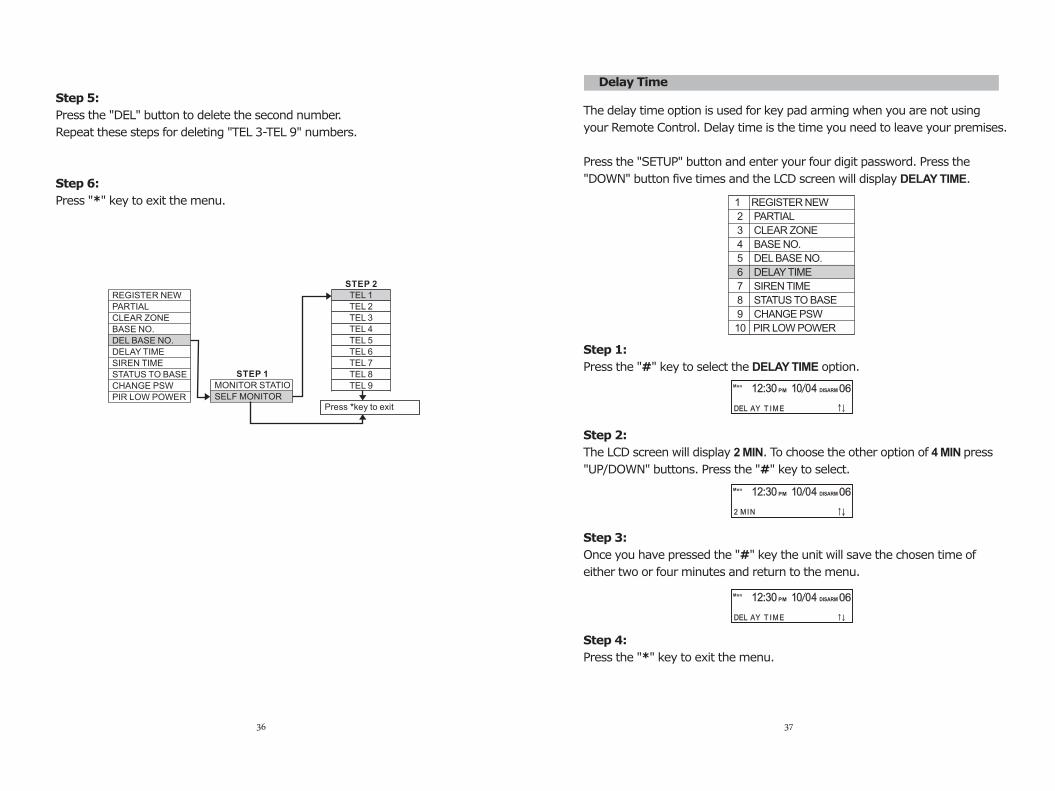
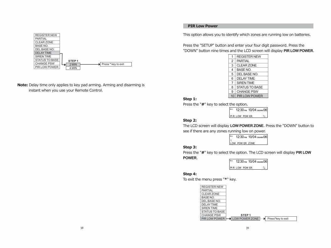
The delay time option is used for key pad arming when you are not using
your Remote Control. Delay time is the time you need to leave your premises.
Press the "SETUP" button and enter your four digit password. Press the
"DOWN" button five times and the LCD screen will display DELAY TIME.
Step 1:
Press the "#" key to select the DELAY TIME option.
Step 2:
The LCD screen will display 2 MIN. To choose the other option of 4 MIN press
"UP/DOWN" buttons. Press the "#" key to select.
Step 3:
Once you have pressed the "#" key the unit will save the chosen time of
either two or four minutes and return to the menu.
Step 4:
Press the "*" key to exit the menu.
Step 5:
Press the "DEL" button to delete the second number.
Repeat these steps for deleting "TEL 3-TEL 9" numbers.
Step 6:
Press "*" key to exit the menu.
TEL 1
TEL 2
TEL 3
TEL 4
TEL 5
TEL 6
TEL 7
TEL 8
TEL 9
REGISTER NEW
PARTIAL
CLEAR ZONE
BASE NO.
DEL BASE NO.
DELAY TIME
SIREN TIME
STATUS TO BASE
CHANGE PSW
PIR LOW POWER
STEP 2
MONITOR STATIO
SELF MONITOR
STEP 1
Press *key to exit
36
Delay Time
1 REGISTER NEW
2 PARTIAL
3 CLEAR ZONE
4 BASE NO.
5 DEL BASE NO.
6 DELAY TIME
7 SIREN TIME
8 STATUS TO BASE
9 CHANGE PSW
10 PIR LOW POWER
MonPM DISARM12:30 10 04 06
DEL AY T IME
MonPM DISARM12:30 10 04 06
2 MIN
MonPM DISARM12:30 10 04 06
DEL AY T IME
37
2 MIN
4 MIN
REGISTER NEW
PARTIAL
CLEAR ZONE
BASE NO.
DEL BASE NO.
DELAY TIME
SIREN TIME
STATUS TO BASE
CHANGE PSW
PIR LOW POWER
STEP 1 Press * key to exit
Note: Delay time only applies to key pad arming. Arming and disarming is
instant when you use your Remote Control.
38
PIR Low Power
MonPM DISARM12:30 10 04 06
1LOW POW ER ZONE
MonPM DISARM12:30 10 04 06
PI R LOW POW ER
MonPM DISARM12:30 10 04 06
PI R LOW POW ER
This option allows to identify which zones are running low on batteries.
Press the "SETUP" button and enter your four digit password. Press the
"DOWN" button nine times and the LCD screen will display PIR LOW POWER.
Step 1:
Press the "#" key to select the option.
Step 2:
The LCD screen will display LOW POWER ZONE. Press the "DOWN" button to
see if there are any zones running low on power.
Step 3:
Press the "#" key to select the option. The LCD screen will display PIR LOW
POWER.
Step 4:
To exit the menu press "*" key.
you
LOW POWER ZONE
REGISTER NEW
PARTIAL
CLEAR ZONE
BASE NO.
DEL BASE NO.
DELAY TIME
SIREN TIME
STATUS TO BASE
CHANGE PSW
PIR LOW POWER
STEP 1 Press*key to exit
39
1 REGISTER NEW
2 PARTIAL
3 CLEAR ZONE
4 BASE NO.
5 DEL BASE NO.
6 DELAY TIME
7 SIREN TIME
8 STATUS TO BASE
9 CHANGE PSW
10 PIR LOW POWER
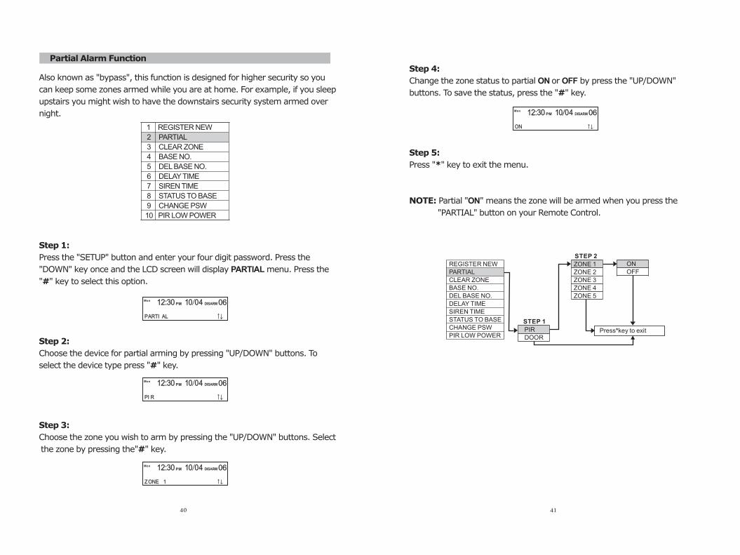
Partial Alarm Function
MonPM DISARM12:30 10 04 06
ON 1 REGISTER NEW
2 PARTIAL
3 CLEAR ZONE
4 BASE NO.
5 DEL BASE NO.
6 DELAY TIME
7 SIREN TIME
8 STATUS TO BASE
9 CHANGE PSW
10 PIR LOW POWER
MonPM DISARM12:30 10 04 06
PARTI AL
MonPM DISARM12:30 10 04 06
PI R
MonPM DISARM12:30 10 04 06
ZONE 1
Also known as "bypass", this function is designed for higher security so you
can keep some zones armed while you are at home. For example, if you sleep
upstairs you might wish to have the downstairs security system armed over
night.
Step 1:
Press the "SETUP" button and enter your four digit password. Press the
"DOWN" key once and the LCD screen will display PARTIAL menu. Press the
"#" key to select this option.
Step 2:
Choose the device for partial arming by pressing "UP/DOWN" buttons. To
select the device type press "#" key.
Step 3:
Choose the zone you wish to arm by pressing the "UP/DOWN" buttons. Select
the zone by pressing the"#" key.
40
ON
OFFREGISTER NEW
PARTIAL
CLEAR ZONE
BASE NO.
DEL BASE NO.
DELAY TIME
SIREN TIME
STATUS TO BASE
CHANGE PSW
PIR LOW POWERPIR
DOOR
ZONE 1
ZONE 2
ZONE 3
ZONE 4
ZONE 5
STEP 1
STEP 2
Press*key to exit
Step 4:
Change the zone status to partial ON or OFF by press the "UP/DOWN"
buttons. To save the status, press the "#" key.
Step 5:
Press "*" key to exit the menu.
NOTE: Partial "ON" means the zone will be armed when you press the
"PARTIAL" button on your Remote Control.
41
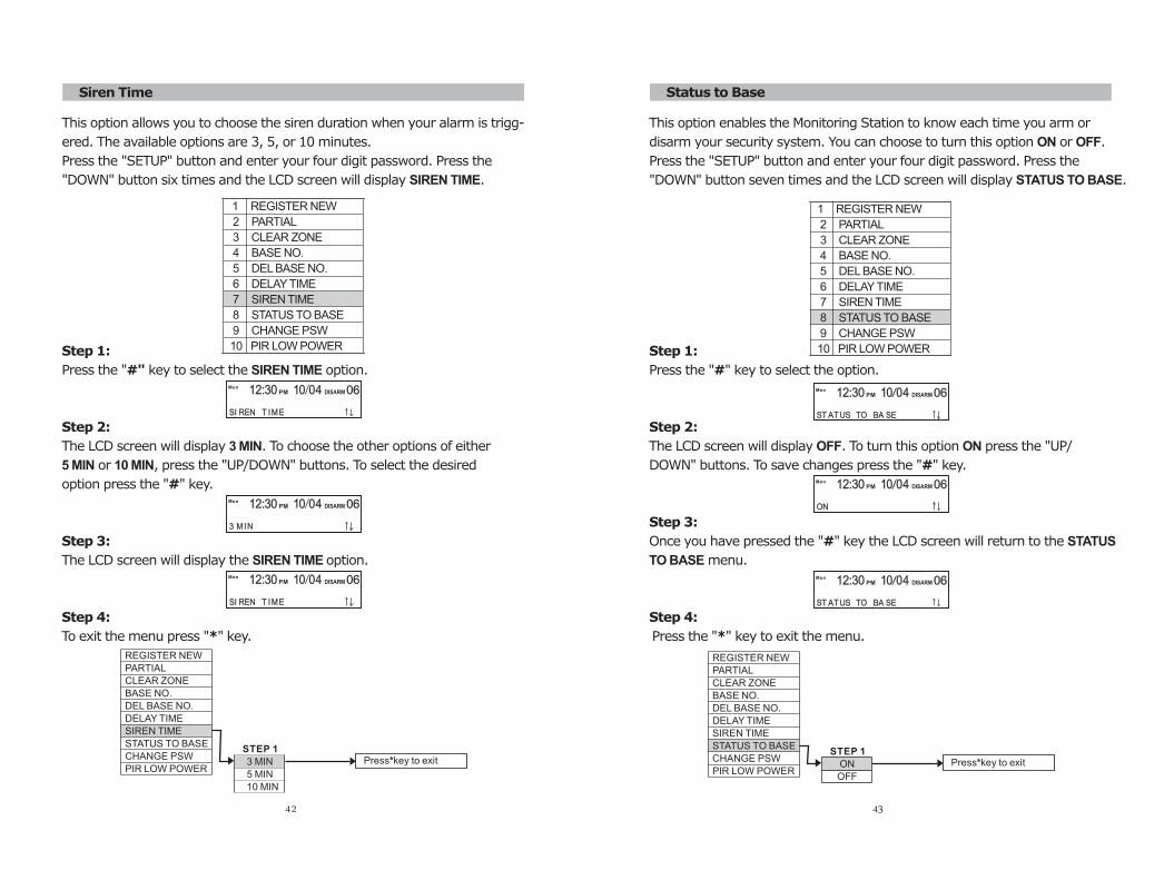
Siren Time
3 MIN
5 MIN
10 MIN
REGISTER NEW
PARTIAL
CLEAR ZONE
BASE NO.
DEL BASE NO.
DELAY TIME
SIREN TIME
STATUS TO BASE
CHANGE PSW
PIR LOW POWER
STEP 1 Press*key to exit
1 REGISTER NEW
2 PARTIAL
3 CLEAR ZONE
4 BASE NO.
5 DEL BASE NO.
6 DELAY TIME
7 SIREN TIME
8 STATUS TO BASE
9 CHANGE PSW
10 PIR LOW POWER
MonPM DISARM12:30 10 04 06
SI REN T IME
MonPM DISARM12:30 10 04 06
3 MIN
MonPM DISARM12:30 10 04 06
SI REN T IME
This option allows you to choose the siren duration when your alarm is trigg-
ered. The available options are 3, 5, or 10 minutes.
Press the "SETUP" button and enter your four digit password. Press the
"DOWN" button six times and the LCD screen will display SIREN TIME.
Step 1:
Press the "#" key to select the SIREN TIME option.
Step 2:
The LCD screen will display 3 MIN. To choose the other options of either
5 MIN or 10 MIN, press the "UP/DOWN" buttons. To select the desired
option press the "#" key.
Step 3:
The LCD screen will display the SIREN TIME option.
Step 4:
To exit the menu press "*" key.
42
Status to Base
MonPM DISARM12:30 10 04 06
ST ATUS TO BA SE
1 REGISTER NEW
2 PARTIAL
3 CLEAR ZONE
4 BASE NO.
5 DEL BASE NO.
6 DELAY TIME
7 SIREN TIME
8 STATUS TO BASE
9 CHANGE PSW
10 PIR LOW POWER
MonPM DISARM12:30 10 04 06
ON
MonPM DISARM12:30 10 04 06
ST ATUS TO BA SE
This option enables the Monitoring Station to know each time you arm or
disarm your security system. You can choose to turn this option ON or OFF.
Press the "SETUP" button and enter your four digit password. Press the
"DOWN" button seven times and the LCD screen will display STATUS TO BASE.
Step 1:
Press the "#" key to select the option.
Step 2:
The LCD screen will display OFF. To turn this option ON press the "UP/
DOWN" buttons. To save changes press the "#" key.
Step 3:
Once you have pressed the "#" key the LCD screen will return to the STATUS
TO BASE menu.
Step 4:
Press the "*" key to exit the menu.
43
ON
OFF
REGISTER NEW
PARTIAL
CLEAR ZONE
BASE NO.
DEL BASE NO.
DELAY TIME
SIREN TIME
STATUS TO BASE
CHANGE PSW
PIR LOW POWER
STEP 1 Press*key to exit
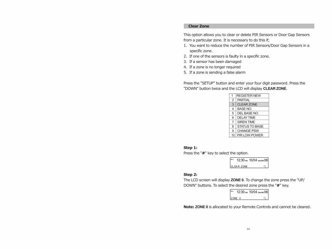
Clear Zone
MonPM DISARM12:30 10 04 06
ZONE 0
This option allows you to clear or delete PIR Sensors or Door Gap Sensors
from a particular zone. It is necessary to do this if;
1. You want to reduce the number of PIR Sensors/Door Gap Sensors in a
specific zone.
2. If one of the sensors is faulty in a specific zone.
3. If a sensor has been damaged
4. If a zone is no longer required
5. If a zone is sending a false alarm
Press the "SETUP" button and enter your four digit password. Press the
"DOWN" button twice and the LCD will display CLEAR ZONE.
Step 1:
Press the "#" key to select the option.
Step 2:
The LCD screen will display ZONE 0. To change the zone press the "UP/
DOWN" buttons. To select the desired zone press the "#" key.
Note: ZONE 0 is allocated to your Remote Controls and cannot be cleared.
1 REGISTER NEW
2 PARTIAL
3 CLEAR ZONE
4 BASE NO.
5 DEL BASE NO.
6 DELAY TIME
7 SIREN TIME
8 STATUS TO BASE
9 CHANGE PSW
10 PIR LOW POWER
MonPM DISARM12:30 10 04 06
CL EA R ZONE
44
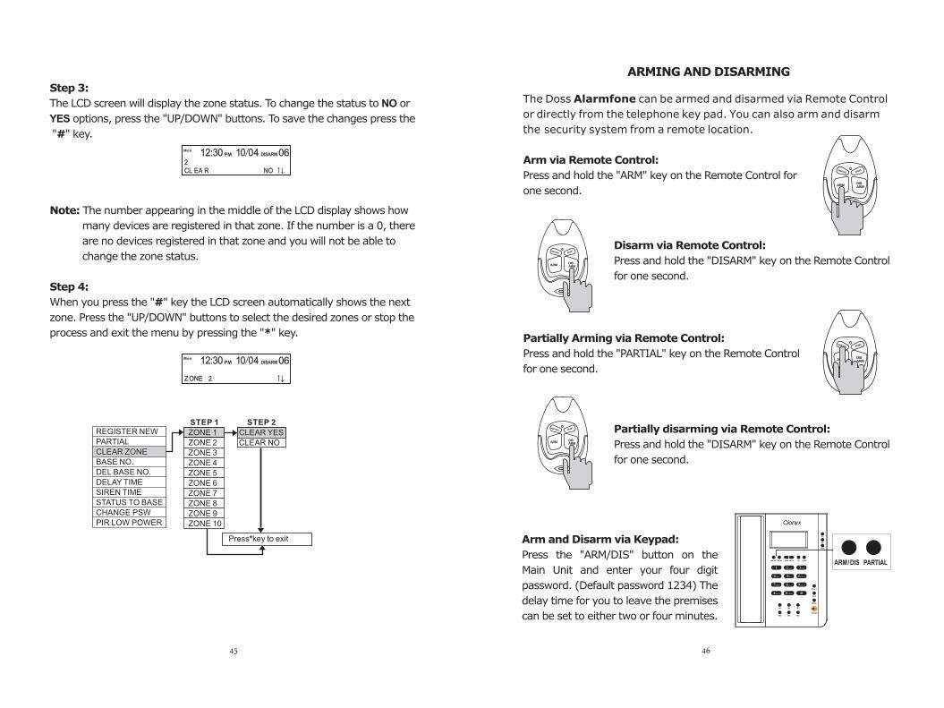
Step 3:
The LCD screen will display the zone status. To change the status to NO or
YES options, press the "UP/DOWN" buttons. To save the changes press the
"#" key.
Note: The number appearing in the middle of the LCD display shows how
many devices are registered in that zone. If the number is a 0, there
are no devices registered in that zone and you will not be able to
change the zone status.
Step 4:
When you press the "#" key the LCD screen automatically shows the next
zone. Press the "UP/DOWN" buttons to select the desired zones or stop the
process and exit the menu by pressing the "*" key.
45
ARMING AND DISARMING
The Doss Alarmfone can be armed and disarmed via Remote Control
or directly from the telephone key pad. You can also arm and disarm
the security system from a remote location.
Arm via Remote Control:
Press and hold the "ARM" key on the Remote Control for
one second.
Disarm via Remote Control:
Press and hold the "DISARM" key on the Remote Control
for one second.
Partially Arming via Remote Control:
Press and hold the "PARTIAL" key on the Remote Control
for one second.
Partially disarming via Remote Control:
Press and hold the "DISARM" key on the Remote Control
for one second.
Press the "ARM/DIS" button on the
Main Unit and enter your four digit
password. (Default password 1234) The
delay time for you to leave the premises
can be set to either two or four minutes.
Arm and Disarm via Keypad:
46
CLEAR YES
CLEAR NO
REGISTER NEW
PARTIAL
CLEAR ZONE
BASE NO.
DEL BASE NO.
DELAY TIME
SIREN TIME
STATUS TO BASE
CHANGE PSW
PIR LOW POWER
ZONE 1
ZONE 2
ZONE 3
ZONE 4
ZONE 5
ZONE 6
ZONE 7
ZONE 8
ZONE 9
ZONE 10
STEP 1 STEP 2
Press*key to exit
MonPM DISARM12:30 10 04 06
ZONE 2
MonPM DISARM12:30 10 04 06
CL EA R NO 2

1 2 3
4 5 6
7 8 9
0 #
00:00 00 0 0 00MonPM DISARM
REMOTE CONTROL
Partial Arming via Keypad:
Press the "PARTIAL" button on your Main Unit and then enter your four digit
password.
Partial Disarming via Keypad:
Press the "ARM/DIS" button on your Main Unit and enter your four digit
password.
Panic:
To activate a panic alarm, press and hold the "PANIC" key
on your Remote Control for one second.
Medical Emergency:
To activate a medical alarm, press and hold the button on
your Medical Alert Pendant for one second.
Arming and Disarming from A Remote Location:
To arm and disarm your Doss Alarmfone from a remote location, call
the Doss Alarmfone number.
47
Step 1:
The alarm unit will answer after nine ring tones and the caller will hear two
beeps.
Step 2:
Input your four digit password using the telephone keypad. If the password
is correct the caller will hear one beep. REMOTE CONTROL will be displayed
on the LCD screen of the Main Unit and the system goes into Remote Control
mode.
If the password is incorrect, the caller will hear four short beeps. You may try
again but you may only make three attempts in total.
Step 3:
To arm the security system press the " " button on your telephone keypad.
The Main Unit will beep once to indicate it is armed. To disarm press the "3"
button on your keypad and the unit will beep twice to indicate it is disarmed.
You can also "spot listen-in" for up to 45 seconds to see if there's anything
going on in your house. Press "1" for this function.
Step 4:
To log out simply hang up.
2
48
49
Tamper alarm:
Tamper alarm occurs when someone tries to remove a PIR or its batteries or
cause any kind of damage to the PIR while the security system armed.
Intruder alarm:
Intruder alarm occurs when a PIR detects a movement while the security
system is armed.
Forced entry:
Forced entry alarm means a Door Gap Sensor has been triggered and
someone has made an unauthorised entry into your premises via the door
or window.
Panic:
Panic alarm indicates an emergency situation and is triggered from the
Remote Control. A panic alert will be picked up and processed by the security
system even when it is disarmed.
Medical emergency alarm:
Medical emergency alarm denotes medical attention is required and is trigg-
ered by using the MedicalAalert Pendant. A medical emergency alarm will be
picked up and processed by the security system even when it is disarmed.
Gas alarm:
Gas alarm indicates there is a gas leak at your premises. Gas detectors are
on 24/7 and can send the signal whether your security system is armed or
disarmed.
Smoke alarm:
Smoke alarm indicates there is a fire at your premises. Smoke alarms are on
24/7 and can send the signal whether your security system is armed or
disarmed.
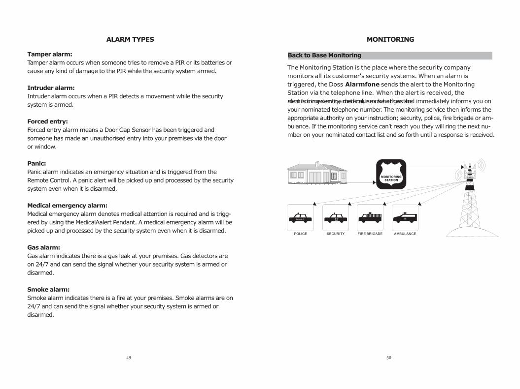
ALARM TYPES MONITORING
The Monitoring Station is the place where the security company
monitors all its customer's security systems. When an alarm is
triggered, the Doss Alarmfone sends the alert to the Monitoring
Station via the telephone line. When the alert is received, the
monitoring service determines whether the alert is forced entry, medical, smoke or gas and immediately informs you on
your nominated telephone number. The monitoring service then informs the
appropriate authority on your instruction; security, police, fire brigade or am-
bulance. If the monitoring service can't reach you they will ring the next nu-
mber on your nominated contact list and so forth until a response is received.
Back to Base Monitoring
MONITORING STATION
POLICE
POLICE
AMBULANCESECURITY FIRE BRIGADE
50
51 52
The self monitoring function works in the same way as Back to Base
Monitor-ing except that the Doss Alarmfone sends the alert directly to
you via the telephone line. When the alarm is triggered the security
system sends the alert to the mobile or landline numbers you have
programmed into the Main Unit. When you receive the call from your
security system you will hear an alarm sound indicating the cause of
the alert.
Note: You will not know which zone is affected. Only a Monitoring Station has
the necessary set up to provide this information.
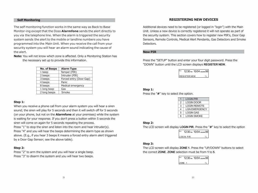
Step 1:
When you receive a phone call from your alarm system you will hear a siren
sound; the siren will play for 5 seconds and then it will switch off for 5 seconds
(on your phone, but not on the Alarmfone at your premises) while the system
is waiting for your response. If you don't press a button within 5 seconds the
siren will come on again for 5 seconds repeating the process.
Press "1" to stop the siren and listen into the room and hear intruder(s).
Press "4" and you will hear the beeps determining the alarm type as shown
above. (E.g., if you hear 3 beeps it means a forced entry alarm alert triggered
by a Door Gap Sensor; see the above table).
Step 2:
Press "2" to arm the system and you will hear a single beep.
Press "3" to disarm the system and you will hear two beeps.
No. of Beeps Alarm Type
1 beep Tamper (PIR)
2 beeps Intruder (PIR)
3 beeps Forced entry (Door Gap)
4 beeps Panic
8 beeps Medical emergency
1 long beep Gas
2 long beeps Smoke
Sel f Monitoring REGISTERING NEW DEVICES
New PIR
5
Additional devices need to be registered (or logged in "login") with the Main
Unit. Unless a new device is correctly registered it will not operate as part of
the security system. This section covers how to register new PIR's, Door Gap
Sensors, Remote Controls, Medical Alert Pendants, Gas Detectors and Smoke
Detectors.
Press the "SETUP" button and enter your four digit password. Press the
"DOWN" button until the LCD screen displays REGISTER NEW.
Step 1:
Press the "#" key to select the option.
Step 2:
The LCD screen will display LOGIN PIR. Press the "#" key to select the option
Step 3:
The LCD screen will display ZONE 1. Press the "UP/DOWN" buttons to select
the correct ZONE. ZONE selection must be from 1 to .
1 LOGIN PIR
2 LOGIN DOOR
3 LOGIN REMOTE
4 LGN EMERGENCY
5 LOGIN GAS
6 LOGIN SMOKE
LOG IN P IR
MonPM DISARM12:30 10 04 06
MonPM DISARM12:30 10 04 06
ZONE 1
REGI STER NEW
MonPM DISARM12:30 10 04 06
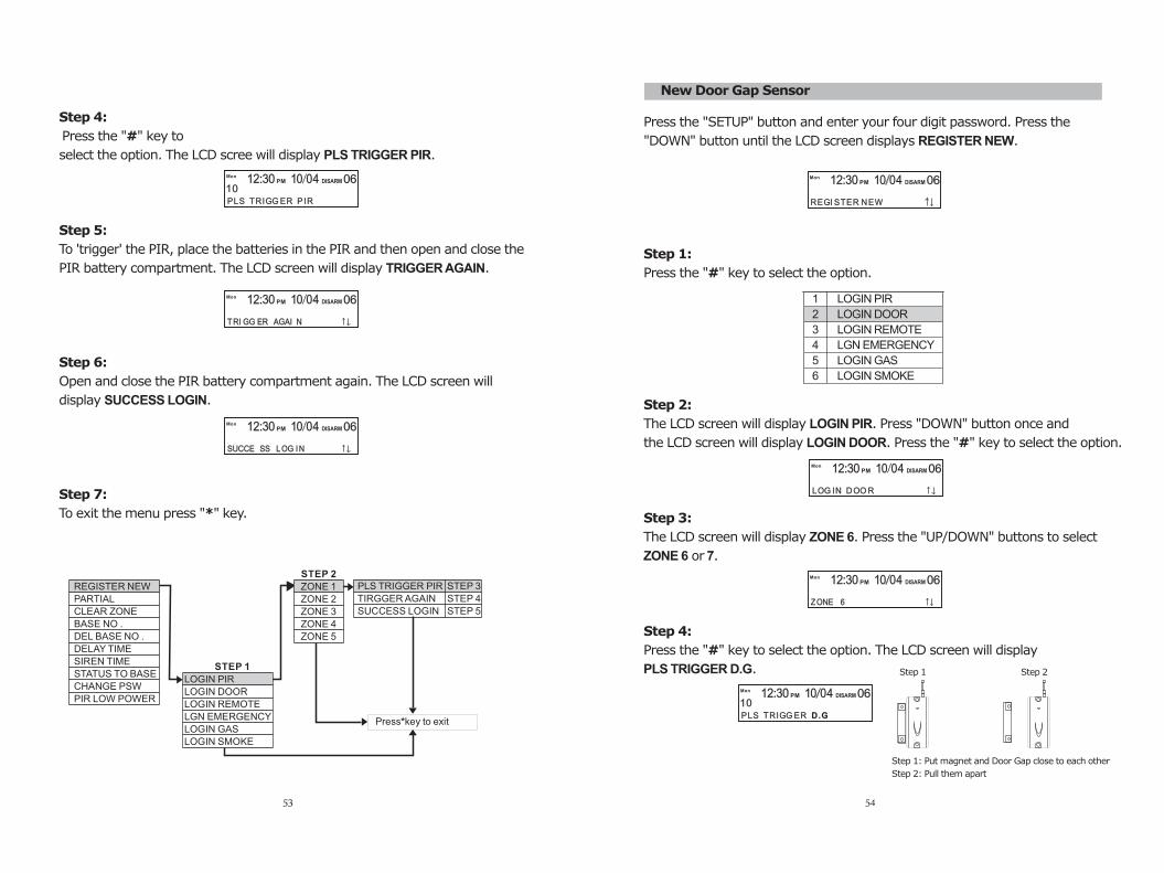
Step 4:
Press the "#" key to
select the option. The LCD scree will display PLS TRIGGER PIR.
Step 5:
To 'trigger' the PIR, place the batteries in the PIR and then open and close the
PIR battery compartment. The LCD screen will display TRIGGER AGAIN.
Step 6:
Open and close the PIR battery compartment again. The LCD screen will
display SUCCESS LOGIN.
Step 7:
To exit the menu press "*" key.
53
MonPM DISARM12:30 10 04 06
SUCCE SS LOG IN
REGISTER NEW
PARTIAL
CLEAR ZONE
BASE NO .
DEL BASE NO .
DELAY TIME
SIREN TIME
STATUS TO BASE
CHANGE PSW
PIR LOW POWER
PLS TRIGGER PIR
TIRGGER AGAIN
SUCCESS LOGIN
STEP 3
STEP 4
STEP 5
STEP 2
ZONE 1
ZONE 2
ZONE 3
ZONE 4
ZONE 5
LOGIN PIR
LOGIN DOOR
LOGIN REMOTE
LGN EMERGENCY
LOGIN GAS
LOGIN SMOKE
STEP 1
Press*key to exit
MonPM DISARM12:30 10 04 06
TRI GG ER AGAI N
PLS TRIGG ER P IR
MonPM DISARM12:30 10 04 06
10
New Door Gap Sensor
Press the "SETUP" button and enter your four digit password. Press the
"DOWN" button until the LCD screen displays REGISTER NEW.
Step 1:
Press the "#" key to select the option.
Step 2:
The LCD screen will display LOGIN PIR. Press "DOWN" button once and
the LCD screen will display LOGIN DOOR. Press the "#" key to select the option.
Step 3:
The LCD screen will display ZONE 6. Press the "UP/DOWN" buttons to select
ZONE 6 or 7.
Step 4:
Press the "#" key to select the option. The LCD screen will display
PLS TRIGGER D.G.
54
1 LOGIN PIR
2 LOGIN DOOR
3 LOGIN REMOTE
4 LGN EMERGENCY
5 LOGIN GAS
6 LOGIN SMOKE
LOG IN DOO R
MonPM DISARM12:30 10 04 06
MonPM DISARM12:30 10 04 06
ZONE 6
REGI STER NEW
MonPM DISARM12:30 10 04 06
PLS TRIGG ER D.G
MonPM DISARM12:30 10 04 06
10
Step 1: Put magnet and Door Gap close to each other
Step 2: Pull them apart
Step 1 Step 2

55 56
Step65:
Put the magnet and sensor together again and then separate them. The LCD
screen will display SUCCESS LOGIN.
Step 7:
To exit the menu press "*" key.
Step 5:
To 'trigger' the Door Gap Sensor, insert the battery and put the magnet
and sensor together and then separate them. The LCD screen will display
TRIGGER AGAIN.
REGISTER NEW
PARTIAL
CLEAR ZONE
BASE NO .
DEL BASE NO .
DELAY TIME
SIREN TIME
STATUS TO BASE
CHANGE PSW
PIR LOW POWER
LOGIN PIR
LOGIN DOOR
LOGIN REMOTE
LGN EMERGENCY
LOGIN GAS
LOGIN SMOKE
STEP 1
STEP 2
ZONE 6
ZONE 7PLS TRIGGER DG. STEP 3
TRIGGER AGAIN STEP 4
SUCCESS LOGIN STEP 5
Press*key to exit
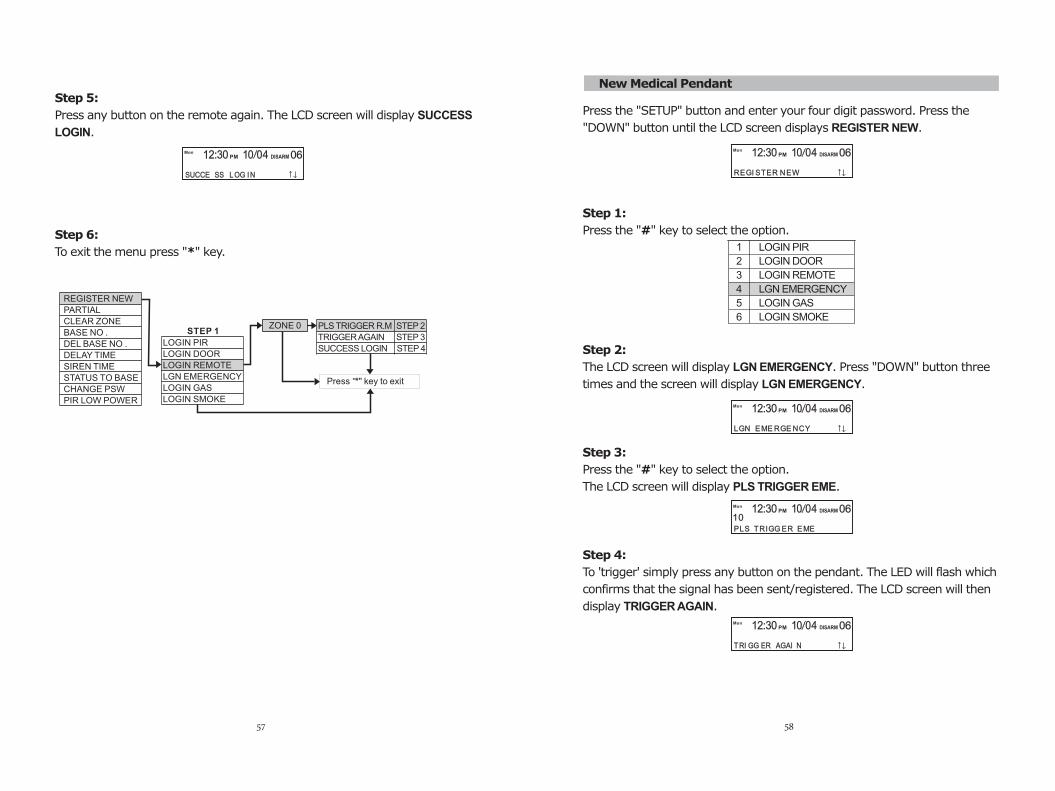
New Remote Control
Press the "SETUP" button and enter your four digit password. Press the
"DOWN" button until the LCD screen displays REGISTER NEW.
Step 1:
Press the "#" key to select the option.
Step 2:
The LCD screen will display Press "DOWN" button twice
and the screen will display LOGIN REMOTE.
Step 3:
Press the "#" key to select the option.
The LCD screen will display PLS TRIGGER R.M.
Step 4:
To 'trigger' simply press any button on the remote. The LED will flash which
confirms that the signal has been sent/registered. The LCD screen will then
display TRIGGER AGAIN.
LOGIN PIR.
1 LOGIN PIR
2 LOGIN DOOR
3 LOGIN REMOTE
4 LGN EMERGENCY
5 LOGIN GAS
6 LOGIN SMOKE
LOG IN REMO TE
MonPM DISARM12:30 10 04 06
PLS TRIGG ER R .M
MonPM DISARM12:30 10 04 06
10
MonPM DISARM12:30 10 04 06
TRI GG ER AGAI N
MonPM DISARM12:30 10 04 06
SUCCE SS LOG IN
MonPM DISARM12:30 10 04 06
SUCCE SS LOG IN
MonPM DISARM12:30 10 04 06
TRI GG ER AGAI N
MonPM DISARM12:30 10 04 06
TRI GG ER AGAI N REGI STER NEW
MonPM DISARM12:30 10 04 06
PLS TRIGGER R.M STEP 2
TRIGGER AGAIN STEP 3
SUCCESS LOGIN STEP 4
REGISTER NEW
PARTIAL
CLEAR ZONE
BASE NO .
DEL BASE NO .
DELAY TIME
SIREN TIME
STATUS TO BASE
CHANGE PSW
PIR LOW POWER
LOGIN PIR
LOGIN DOOR
LOGIN REMOTE
LGN EMERGENCY
LOGIN GAS
LOGIN SMOKE
STEP 1ZONE 0
Press "*" key to exit
Step 5:
Press any button on the remote again. The LCD screen will display SUCCESS
LOGIN.
Step 6:
To exit the menu press "*" key.
57
New Medical Pendant
Press the "SETUP" button and enter your four digit password. Press the
"DOWN" button until the LCD screen displays REGISTER NEW.
Step 1:
Press the "#" key to select the option.
Step 2:
The LCD screen will d
NCY.
Step 3:
Press the "#" key to select the option.
The LCD screen will display PLS TRIGGER EME.
Step 4:
To 'trigger' simply press any button on the pendant. The LED will flash which
confirms that the signal has been sent/registered. The LCD screen will then
display TRIGGER AGAIN.
isplay LGN EMERGENCY. Press "DOWN" button three
times and the screen will display LGN EMERGE
1 LOGIN PIR
2 LOGIN DOOR
3 LOGIN REMOTE
4 LGN EMERGENCY
5 LOGIN GAS
6 LOGIN SMOKE
LGN EME RGE NCY
MonPM DISARM12:30 10 04 06
PLS TRIGG ER EME
MonPM DISARM12:30 10 04 06
10
MonPM DISARM12:30 10 04 06
TRI GG ER AGAI N
58
REGI STER NEW
MonPM DISARM12:30 10 04 06Mon
PM DISARM12:30 10 04 06
SUCCE SS LOG IN
59
Press the "SETUP" button and enter your four digit password. Press the
"DOWN" button until the LCD screen displays REGISTER NEW.
Step 1:
Press the "#" key to select the option.
Step 2:
The LCD screen will display LOGIN PIR. Press "DOWN" button four times
and the screen will display LOGIN GAS.
Step 3:
Press the "#" key to select the option.
The LCD screen will display PLS TRIGGER GAS.
Step 4:
To 'trigger' please refer to the gas detector user manual. The LCD screen will
then display TRIGGER AGAIN.
1 LOGIN PIR
2 LOGIN DOOR
3 LOGIN REMOTE
4 LGN EMERGENCY
5 LOGIN GAS
6 LOGIN SMOKE
PLS TRIGG ER GAS
MonPM DISARM12:30 10 04 06
10
MonPM DISARM12:30 10 04 06
TRI GG ER AGAIN
60
REGI STER NEW
PM DISARM12:30 10 04 06
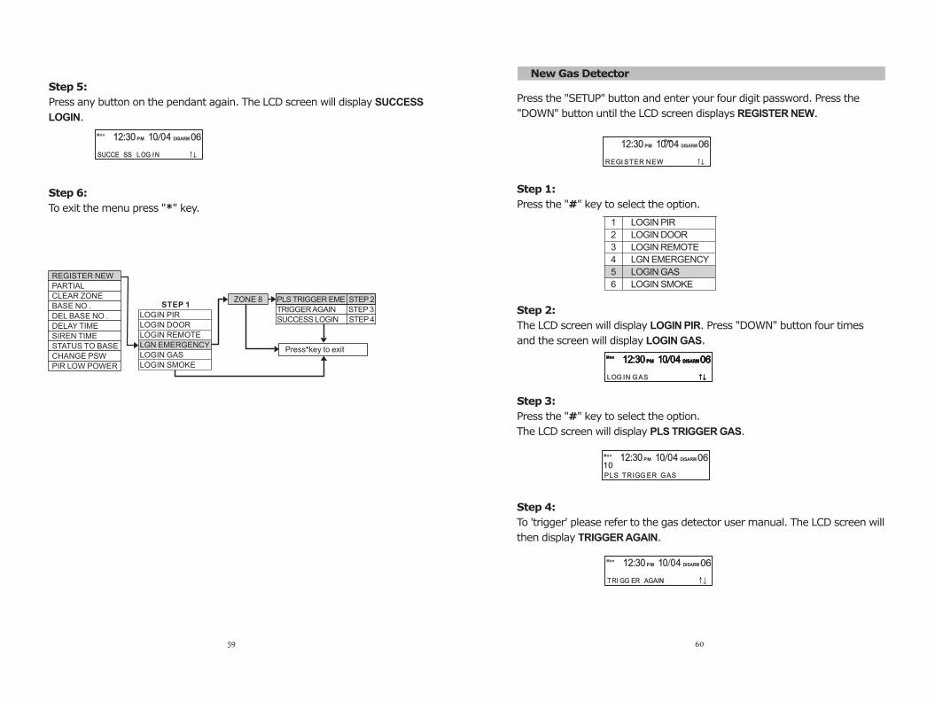
Step 5:
Press any button on the pendant again. The LCD screen will display SUCCESS
LOGIN.
Step 6:
To exit the menu press "*" key.
STEP 1ZONE 8 PLS TRIGGER EME STEP 2
TRIGGER AGAIN STEP 3
SUCCESS LOGIN STEP 4
Press*key to exit
REGISTER NEW
PARTIAL
CLEAR ZONE
BASE NO .
DEL BASE NO .
DELAY TIME
SIREN TIME
STATUS TO BASE
CHANGE PSW
PIR LOW POWER
LOGIN PIR
LOGIN DOOR
LOGIN REMOTE
LGN EMERGENCY
LOGIN GAS
LOGIN SMOKE
New Gas Detector
MonPM DISARM12:30 10 04 06
LOG IN GAS
MonPM DISARM12:30 10 04 06MonPM DISARM12:30 10 04 06MonPM DISARM12:30 10 04 06
Mon
MonPM DISARM12:30 10 04 06
SUCCE SS LOG IN
61
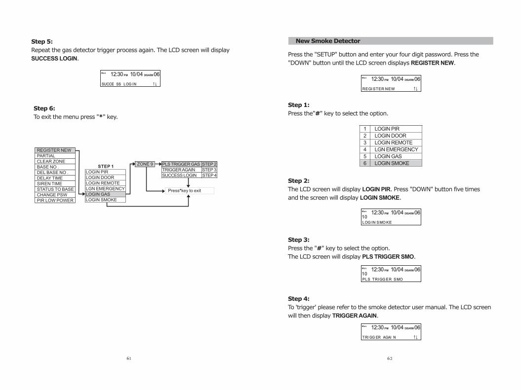
Press the "SETUP" button and enter your four digit password. Press the
"DOWN" button until the LCD screen displays REGISTER NEW.
Step 1:
Press the"#" key to select the option.
Step 2:
The LCD screen will display LOGIN PIR. Press "DOWN" button five times
and the screen will display LOGIN SMOKE.
Step 3:
Press the "#" key to select the option.
The LCD screen will display PLS TRIGGER SMO.
Step 4:
To 'trigger' please refer to the smoke detector user manual. The LCD screen
will then display TRIGGER AGAIN.
New Smoke Detector
1 LOGIN PIR
2 LOGIN DOOR
3 LOGIN REMOTE
4 LGN EMERGENCY
5 LOGIN GAS
6 LOGIN SMOKE
PLS TRIGG ER SMO
MonPM DISARM12:30 10 04 06
10
MonPM DISARM12:30 10 04 06
TRI GG ER AGAI N
62
REGISTER NEW
PARTIAL
CLEAR ZONE
BASE NO .
DEL BASE NO .
DELAY TIME
SIREN TIME
STATUS TO BASE
CHANGE PSW
PIR LOW POWER
LOGIN PIR
LOGIN DOOR
LOGIN REMOTE
LGN EMERGENCY
LOGIN GAS
LOGIN SMOKE
STEP 1ZONE 9 PLS TRIGGER GAS STEP 2
TRIGGER AGAIN STEP 3
SUCCESS LOGIN STEP 4
Press*key to exit
Step 6:
To exit the menu press "*" key.
REGI STER NEW
MonPM DISARM12:30 10 04 06
LOG IN SMO KE
MonPM DISARM12:30 10 04 06
10
Step 5:
Repeat the gas detector trigger process again. The LCD screen will display
SUCCESS LOGIN.
MonPM DISARM12:30 10 04 06
SUCCE SS LOG IN
63
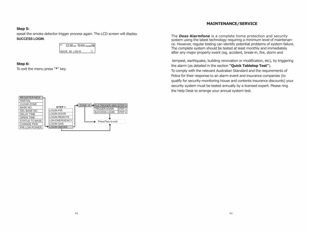
Step 5:
epeat the smoke detector trigger process again. The LCD screen will display
SUCCESS LOGIN.
Step 6:
To exit the menu press "*" key.
REGISTER NEW
PARTIAL
CLEAR ZONE
BASE NO .
DEL BASE NO .
DELAY TIME
SIREN TIME
STATUS TO BASE
CHANGE PSW
PIR LOW POWER
LOGIN PIR
LOGIN DOOR
LOGIN REMOTE
LGN EMERGENCY
LOGIN GAS
LOGIN SMOKE
STEP 1ZONE 10 PLS TRIGGER SMO STEP 2
TRIGGER AGAIN STEP 3
SUCCESS LOGIN STEP 4
Press*key to exit
The Doss Alarmfone is a complete home protection and security system using the latest technology requiring a minimum level of maintenan-ce. However, regular testing can identify potential problems of system failure. The complete system should be tested at least monthly and immediately after any major property event (eg, accident, break-in, fire, storm and
tempest, earthquake, building renovation or modification, etc), by triggering
the alarm (as detailed in the section ).
To comply with the relevant Australian Standard and the requirements of
Police for their response to an alarm event and insurance companies (to
qualify for security-monitoring house and contents insurance discounts) your
security system must be tested annually by a licensed expert. Please ring
the Help Desk to arrange your annual system test.
"Quick Tabletop Test"
MAINTENANCE/SERVICE
64
MonPM DISARM12:30 10 04 06
SUCCE SS LOG IN
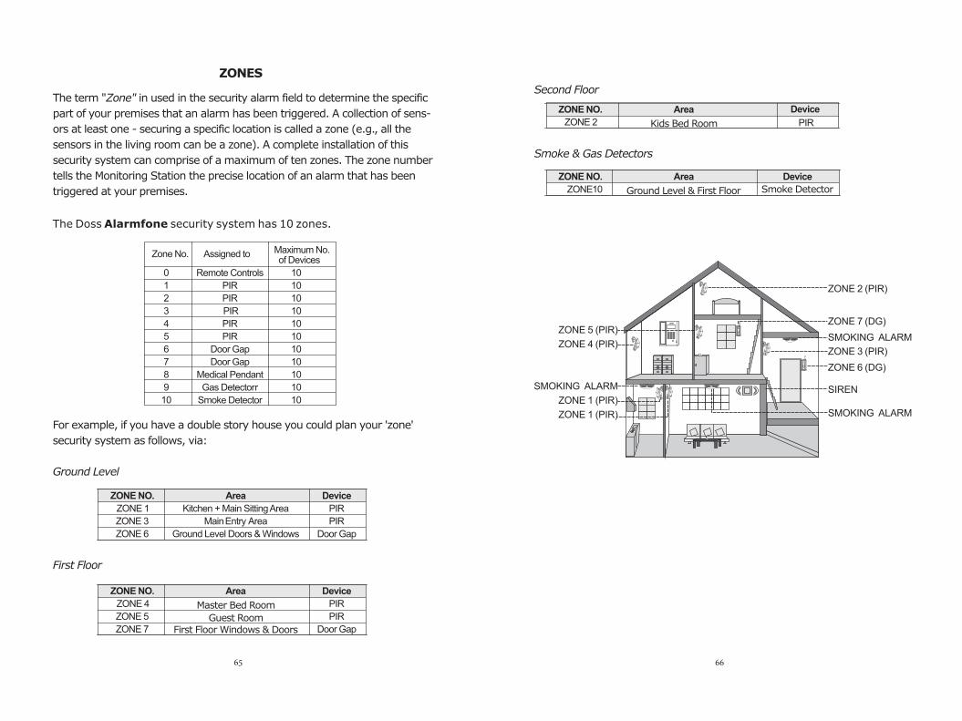
The term "Zone" in used in the security alarm field to determine the specific
part of your premises that an alarm has been triggered. A collection of sens-
ors at least one - securing a specific location is called a zone (e.g., all the
sensors in the living room can be a zone). A complete installation of this
security system can comprise of a maximum of ten zones. The zone number
tells the Monitoring Station the precise location of an alarm that has been
triggered at your premises.
The Doss Alarmfone security system has 10 zones.
For example, if you have a double story house you could plan your 'zone'
security system as follows, via:
Ground Level
First Floor
ZONES
Zone No. Assigned to
Remote Controls
PIR
PIR
PIR
PIR
PIR
Door Gap
Door Gap
Medical Pendant
Gas Detectorr
Smoke Detector
10
10
10
10
10
10
10
10
10
10
10
Maximum No. of Devices
0
1
2
3
4
5
6
7
8
9
10
ZONE NO. Area Device
ZONE 1 Kitchen + Main Sitting Area PIR
ZONE 3 Entry Main Area PIR
ZONE 6 Ground Level Doors & Windows Door Gap
Master Bed Room
Guest RoomFirst Floor Windows & Doors
ZONE NO. Area Device
ZONE 4 PIR
ZONE 5 PIR
ZONE 7 Door Gap
65
Second Floor
Smoke & Gas Detectors
Kids Bed Room
ZONE NO. Area Device
ZONE 2 PIR
Ground Level & First Floor
ZONE NO. Area Device
ZONE 10 Smoke Detector
ZONE 2 (PIR)
ZONE 3 (PIR)
SMOKING ALARM
ZONE 1 (PIR)
ZONE 1 (PIR)
ZONE 7 (DG)
ZONE 6 (DG)
SIREN
ZONE 5
ZONE 4 (PIR)
(PIR)SMOKING ALARM
SMOKING ALARM
66

