water measurement guidebook - alberta.ca › dataset › 4abef720-89a2-4040... · 2.0. measurement...
TRANSCRIPT

water measurement guidebook

TABLE OF CONTENTS
Disclaimer
The information provided in this document is intended as guidance only and is subject to revisions. This document is not a substitute for the law. Please consult the Water Act, the Water (Ministerial) Regulation and the specific authorization issued under the Water Act for all purposes of interpreting and applying the law. In the event that there is a difference between this document and the legislation or authorization, the legislation or authorization prevails.
Alberta Environment is not responsible for any loss, damage or injury resulting from the reader’s use of or reliance on the information and methods contained in this document.
ISBN: 978-0-7785-8535-0
March 2009
1.0 Purpose of the Guidebook 1
2.0 Measurement Methods 2
2.1 Staff Gauge 5
2.2 Velocity-Area Method 7
2.3 Volumetric Method 11
2.4 Rain Gauge 13
2.5 Float Method 17
2.6 Head Rod Method 21
2.7 Weirs 25
2.8 Power Consumption Method 27
3.0 Glossary of Terms 29
4.0 References 29
List of Tables
Table 1. Summary of water measurement methods 3
Table 2. Unit conversion 3
List of Figures
Figure 1. Flowchart for selection of water measurement methods 2

Water Measurement Guidebook 1
1.0 Purpose of the Guidebook
Alberta Environment’s Water Use Reporting System allows licensees to report their water diversions online. Licensees enter the data on a daily, monthly or annual basis depending on the reporting requirement of their licence. Data collected can be entered online in the Water Use Reporting System (WURS) at: http://environment.alberta.ca/1286.html. If you do not have access to WURS please see contact information below.
Water meters are the preferred method of measuring water diversion because of their simplicity and accuracy. However, if licensees are unable to acquire a water meter, the methods in this Guidebook, provide a consistent approach to measuring water diversions.
The Guidebook will help licensees, improve the consistency and accuracy of their water diversion, as well as detect well and pump problems. The data obtained using this Guidebook will also help in the management of Alberta’s water resources and improve efficiency and conservation.
Note to Users: Please note that the Guidebook outlines only direct methods to measure water diversions. Indirect methods, such as estimating water diversion based on livestock water requirements, are not provided.
Contact
Please dial toll-free 310-0000 and ask to speak with an
Alberta Environment water specialist in your region. An
electronic copy of this Guidebook is also available for
download at http://environment.alberta.ca/1286.html

2.0
Mea
sure
men
t met
hods
Th
e fo
llow
ing
sect
ion
pro
vid
es
info
rmat
ion
on t
he d
iffer
ent
typ
es o
f w
ater
div
ersi
on m
easu
rem
ent
met
hod
s.
Eac
h m
etho
d in
Fig
ure
1 ha
s a
corr
esp
ond
ing
wor
kshe
et w
ith s
tep
s fo
r ca
lcul
atin
g th
e vo
lum
e of
wat
er d
iver
ted
. Th
e w
orks
heet
s ou
tline
the
req
uire
men
ts
nece
ssar
y to
do
the
mea
sure
men
ts. U
se
the
flo
w c
har
t in
Fig
ure
1 t
o s
elec
t a
mea
sure
men
t m
eth
od
bas
ed o
n t
he
div
ersi
on t
ype
and
eq
uip
men
t av
aila
ble
to
you
.
Tabl
e 1
is a
sum
mar
y of
key
co
nsi
der
atio
ns
for
the
wat
er u
se
mea
sure
men
t m
eth
od
s d
escr
ibed
in
this
Gu
ideb
oo
k. F
or
som
e ty
pes
of
div
ersi
on
s, m
ore
th
an o
ne
met
ho
d is
p
ote
nti
ally
ap
plic
able
. In
th
ese
case
s,
refe
r to
Tab
le 1
and
the
rel
evan
t se
ctio
ns
be
low
fo
r a
dd
itio
na
l in
form
ati
on
to
det
erm
ine
the
mos
t ap
pro
pria
te m
etho
d.
C. V
olum
etric
Met
hod
Wat
er S
ourc
e
Sur
face
Wat
er
Gro
undw
ater
Pum
p
C. V
olum
etric
Met
hod
H. P
ower
Con
sum
ptio
n
Met
hod
Pum
p
Dug
out/
R
eser
voir
Pum
ping
S
tatio
n
Spr
inkl
er/P
ivot
/ W
heel
Mov
e
Sur
face
Run
off
D. R
ain
Gau
ge
E. F
loat
Met
hod
F. H
ead
Rod
C. V
olum
etric
Met
hod
C. V
olum
etric
Met
hod
B. V
eloc
ity-A
rea
Met
hod
D. R
ain
Gau
ge
No
Pum
p
H. P
ower
Con
sum
ptio
n
Met
hod
Water Measurement Guidebook2
Fig
ure
1. F
low
Cha
rt fo
r se
lect
ion
of w
ater
mea
sure
men
t met
hods
G. W
eir
Cha
nnel
Flo
w
Floo
d Irr
igat
ion
A. S
taff
Gau
ge

Tab
le 1
. Sum
mar
y of
Wat
er M
easu
rem
ent M
etho
ds
Tab
le 2
. Uni
t Con
vers
ion
F
rom
To
M
ultip
ly B
y F
rom
To
M
ultip
ly B
y
A
cre-
foot
U
S g
allo
n 32
5,85
1 C
ubic
foot
C
ubic
met
re
0.02
8
A
cre-
foot
Im
peria
l gal
lon
271,
328
C
ubic
foot
U
S g
allo
n 7.
481
A
cre-
foot
C
ubic
feet
43
, 560
C
ubic
foot
Im
peria
l gal
lon
6.22
9
A
cre-
foot
C
ubic
dec
amet
re
1.23
3 H
ecta
res
Acr
e 2.
471
C
ubic
met
re
US
gal
lon
264.
172
Met
re
Foot
3.
281
C
ubic
met
re
Impe
rial g
allo
n 21
9.96
9 In
ch
Milli
met
re
25.4
C
ubic
met
re
Litr
e 1,
000
Hou
r
Sec
ond
3,60
0
Water Measurement Guidebook 3
M
easu
rem
ent
Con
stru
ctio
n/
Rem
ote
Dat
a
Met
hod
Acc
urac
y C
alib
ratio
n M
aint
enan
ce
Inst
alla
tion
Col
lect
ion
Pos
sibi
lity
Rem
arks
Year
ly fl
ow
S
impl
e to
take
mea
sure
men
t
A. S
taff
Gau
ge
Med
ium
m
easu
rem
ent a
t M
inor
Ye
s N
o bu
t qua
lified
per
son
di
ffere
nt le
vels
requ
ired
to c
alib
rate
B. V
eloc
ity-A
rea
Tr
aini
ng o
r hel
p fro
m
Met
hod
Hig
h N
o N
o N
o N
o qu
alifi
ed p
erso
n re
quire
d
C. V
olum
etri
c M
ediu
m
No
No
Yes
No
M
etho
d
D. R
ain
Gau
ge
Med
ium
N
o N
o Ye
s (T
empo
rary
) N
o
E
. Flo
at M
etho
d Lo
w
No
No
No
No
F.
Hea
d R
od
Low
N
o N
o N
o N
o
Sim
ple
to ta
ke m
easu
rem
ent
G
. Wei
rs
Hig
h Ye
arly
Ye
s Ye
s Ye
s bu
t qua
lified
per
son
requ
ired
m
easu
rem
ent
to
inst
all a
nd c
alib
rate
H
. Pow
er
E
very
C
onsu
mpt
ion
Lo
w
2-3
year
s N
o N
o N
o
Met
hod

Water Measurement Guidebook4

An electronic copy of this guidebook is also available for download at http://environment.alberta.ca/1286.html
The staff gauge method is used to measure flows in open canals and ditches.
A staff gauge is a metal plate with accurately positioned markings. The metal plate is enamelled iron or steel, which is covered with a bake-on porcelain enamel finish to resist rust or discoloration. Typically, the markings are black numbers on a white background but different colours of enamel are also available.
Water level readings can be taken directly off the gauge. The readings can be converted into a water flow rate (cubic metre per second) using a rating curve or a stage-discharge curve that must be developed by a qualified hydrometric technician. To determine the total quantity of water diverted, multiply the flow rate, from the rating curve, by the length of time it took to divert the water past the gauge.
Staff G
auge
2.1 Staff Gauge
➜
Water Measurement Guidebook 5

2.1 Staff GaugeEquipment
1. Installed staff gauge2. Rating table (stage-discharge/storage relationship)
If you do not have a staff gauge, choose another method for which you have the required equipment.
Procedure
1. Read the water level in the canal from the staff gauge and record in column 1
2. Determine the flow rate corresponding to the water level from the rating table previously developed by the hydrometric technician and record in column 2
3. Record hours of operation/diversion in column 3
4. Multiply 2 and 3 by 3,600 to get total water diversion in cubic metres
Observations and Computations Licence No.: Date:
Sta
ff G
auge
Gauge reading Flow rate Hours of operation Total diversion (m) (m3/s) (hours) (m3) [=3,600 x 2 x 3 ] (enter this value online)
1 2 3 4
Water Measurement Guidebook6
Unit Conversion From To Multiply By From To Multiply By
Acre-foot US gallon 325,851 Cubic foot Cubic metre 0.028
Acre-foot Imperial gallon 271, 328 Cubic foot US gallon 7.481
Acre-foot Cubic feet 43, 560 Cubic foot Imperial gallon 6.229
Acre-foot Cubic decametre 1.233 Hectares Acre 2.471
Cubic metre US gallon 264.172 Metre Foot 3.281
Cubic metre Imperial gallon 219.969 Inch Millimetre 25.4
Cubic metre Litre 1,000 Hour Second 3,600
Comments

An electronic copy of this guidebook is also available for download at http://environment.alberta.ca/1286.html
Velocity-Area Method is most commonly used and relatively accurate method for discharge measurement in a stream or an open channel. However, proper training or help from technical person is required to use this method of measurement. In this method, the channel cross-section is divided into subsections and width and depth of water at each subsection are measured. 25-30 sections are recommended in a stream but fewer sections may be used in a small channel with smooth cross section and good velocity distribution. For accurate result space the subsections so that no subsection has more than 10 percent of the total discharge in it. A current meter is used to measure the velocity of flow by observing the number of revolutions and time at each subsection. The observations are usually made at 0.6 times depth of water if the depth of water is less than 75cm and or 0.2 and 0.8 times the depth of water from the water surface for a depth more than 75cm. A Pigmy Meter is used in place of Current Meter for shallow water with depth less than 45cm. The velocity of flow is determined based on observations and the current meter equation or rating table provided by the manufacturer. Discharge through each subsection is computed and the sum of these discharges is the total discharge passing through the cross-section at the time of measurement. The measurement may be carried out by wading, from cableway, bridge or using a boat depending on the local circumstances. Special attention and skill is required to use this method during ice condition. ➜
Water Measurement Guidebook 7
Velocity-Area
Method
2.2 Velocity-Area Method

2.2 Velocity-Area Method Equipment
1. A Current Meter or Pigmy Meter2. Wading rod3. Measuring tape 4. Stop watch 5. Current Meter rating equation or table (provided by manufacturer)
Procedure
1. Select a straight reach of river free of large boulder or any obstructions creating excessive turbulence, eddies or stagnant condition. 2. String a rope or measuring tape across the channel cross section at right angle to the flow direction. 3. Divide the channel cross section into different sub-sections and mark with rope. 25-30 sections are recommended in a stream but fewer sections may be used in a small channel with smooth cross section and good velocity distribution. 4. Measure the distance from a fixed initial point to the first mark and depth of water and record it in column 1 and column 3 respectively. 5. Compute the width of the first subsection in column 2 dividing the difference of distance to first and second mark in column 1 by 2. Compute the width of last subsection in the same way. For computing width of all other intermittent subsections, divide the difference of distances of two adjacent marks in column 1 by 2. 6. Place the current meter (Pigmy Meters if the depth of water is less than 45cm) at a depth 0.6 times the depth of water below the water surface for about 40 to 70 seconds. Make sure that the meter is parallel to the flow and wading rod stands in vertical position. Record the observation point as 0.6 in column 4 . Record the number of revolutions in column 5 and time taken (second) in column 6 . If the depth of water is more than 75cm make observations at 0.2*depth and 0.8*depth below the water surface and record the point of observation as 0.2 and 0.8 in separate rows in column 4 and record the No. of revolutions and time in column 5 and 6
respectively. If the current meter used in the measurement gives the direct velocity of flow record in column 7 . 7. Determine the velocity at point using the equations or rating table provided by manufacturer for the current meter (or Pigmy Meter) used and record in column 7 .
Water Measurement Guidebook8
Unit Conversion From To Multiply By From To Multiply By
Acre-foot US gallon 325,851 Cubic foot Cubic metre 0.028
Acre-foot Imperial gallon 271, 328 Cubic foot US gallon 7.481
Acre-foot Cubic feet 43, 560 Cubic foot Imperial gallon 6.229
Acre-foot Cubic decametre 1.233 Hectares Acre 2.471
Cubic metre US gallon 264.172 Metre Foot 3.281
Cubic metre Imperial gallon 219.969 Inch Millimetre 25.4
Cubic metre Litre 1,000 Hour Second 3,600
Velo
city
-Are
a
Met
hod
Water Measurement Guidebook 9
Procedure continued
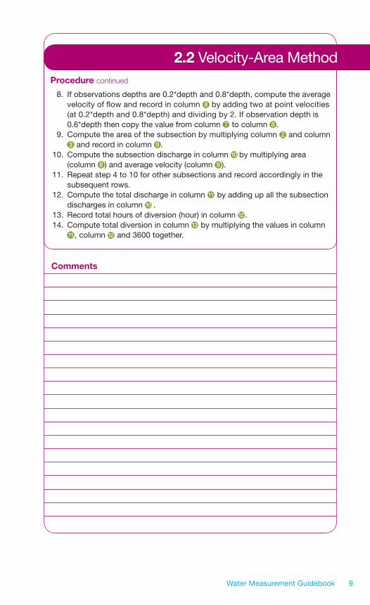
8. If observations depths are 0.2*depth and 0.8*depth, compute the average velocity of flow and record in column 8 by adding two at point velocities (at 0.2*depth and 0.8*depth) and dividing by 2. If observation depth is 0.6*depth then copy the value from column 7 to column 8 . 9. Compute the area of the subsection by multiplying column 2 and column 3 and record in column 9 . 10. Compute the subsection discharge in column 10 by multiplying area (column 8 ) and average velocity (column 9 ). 11. Repeat step 4 to 10 for other subsections and record accordingly in the subsequent rows. 12. Compute the total discharge in column 11 by adding up all the subsection discharges in column 10 . 13. Record total hours of diversion (hour) in column 12 . 14. Compute total diversion in column 13 by multiplying the values in column 11 , column 12 and 3600 together.
Comments
2.2 Velocity-Area Method

Observations and Computations Licence No.: Date:
No
te:
Sep
arat
e m
easu
rem
ent
is r
equi
red
for
div
ersi
ons
at d
iffer
ent
time
and
rat
e.
Water Measurement Guidebook10
2.2 Current Meter Method2.2 Velocity-Area Method
Dis
tanc
e W
idth
(m)
Dep
th O
bser
vatio
n N
o. o
f Ti
me
Velo
city
M
ean
A
rea
Subs
ectio
n To
tal
Tota
l D
iver
sion
fr
om In
itial
[W
1 =
(b2-
b1)/2
(m
) D
epth
R
evol
utio
ns
(s)
at p
oint
Ve
loci
ty
(m2 )
Dis
char
ge
Dis
char
ge
Hou
rs o
f (m
3 )
Poi
nt
W2
or W
x =
(0
.2, 0
.8
(m/s
ec)
(m/s
ec)
[=2
x3
] (m
3 /se
c)
(m3 /
sec)
di
vers
ion
[=36
00x
11x
12]
(m)=
b (b
3-b1
)/2
or
0.6
)
[=8
x9
] [=
∑10
] (h
) (e
nter
thi
s
Wla
st =
(bla
st -
va
lue
onl
ine)
bs
econ
d la
st)/2
]
23
14
56
78
911
1213
10

An electronic copy of this guidebook is also available for download at http://environment.alberta.ca/1286.html
Two types of volumetric measurement methods can be used for measuring water diversions. One method is for measuring small flows through a channel or ditch, pipeline or discharge from pumps.
To measure flows from a small pump or a channel use a measuring container and a stop watch. Use an appropriate-size container to reduce measurement error. A 10-litre container is recommended for flows up to four litres per second. Use a larger container for flows greater than four litres per second.
If high flow rates are encountered, check the pump information brochure for a discharge rate or a pump operating curve. This information may help to establish the diversion rate. If the rating is available, simply multiply the diversion rate by the time the pump operated.
2.3 Volumetric Method
➜
Water Measurement Guidebook 11
Volumetric
Method
2.3 Volumetric Method
4 5 6
Water Measurement Guidebook12
Equipment
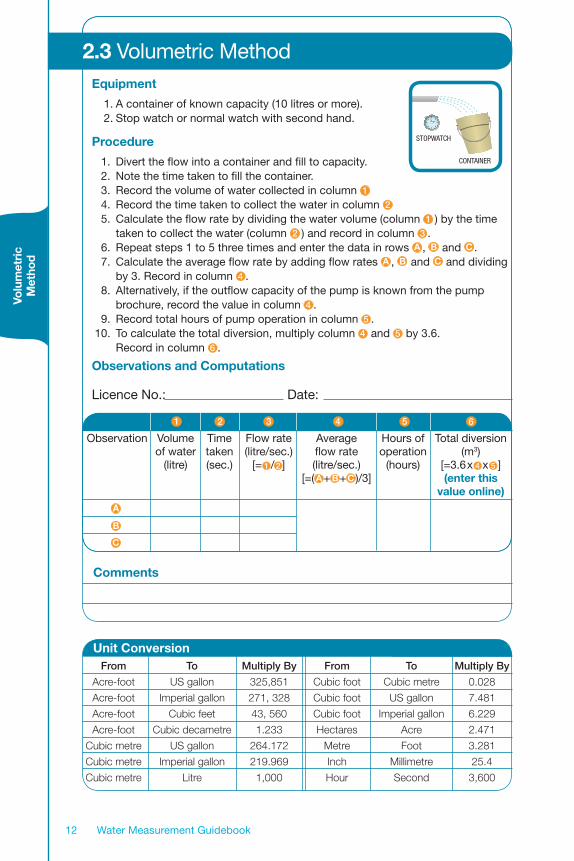
1. A container of known capacity (10 litres or more).2. Stop watch or normal watch with second hand.
Procedure
1. Divert the flow into a container and fill to capacity. 2. Note the time taken to fill the container. 3. Record the volume of water collected in column 1
4. Record the time taken to collect the water in column 2
5. Calculate the flow rate by dividing the water volume (column 1 ) by the time taken to collect the water (column 2 ) and record in column 3 . 6. Repeat steps 1 to 5 three times and enter the data in rows A , B and C . 7. Calculate the average flow rate by adding flow rates A , B and C and dividing by 3. Record in column 4 . 8. Alternatively, if the outflow capacity of the pump is known from the pump brochure, record the value in column 4 . 9. Record total hours of pump operation in column 5 . 10. To calculate the total diversion, multiply column 4 and 5 by 3.6. Record in column 6 .
Observations and Computations
Licence No.: Date:
stopwatch
container
321
Observation Volume Time Flow rate Average Hours of Total diversion of water taken (litre/sec.) flow rate operation (m3) (litre) (sec.) [= 1 /2 ] (litre/sec.) (hours) [=3.6x 4 x 5 ] [=( A+ B+C )/3] (enter this value online)
Unit Conversion From To Multiply By From To Multiply By
Acre-foot US gallon 325,851 Cubic foot Cubic metre 0.028
Acre-foot Imperial gallon 271, 328 Cubic foot US gallon 7.481
Acre-foot Cubic feet 43, 560 Cubic foot Imperial gallon 6.229
Acre-foot Cubic decametre 1.233 Hectares Acre 2.471
Cubic metre US gallon 264.172 Metre Foot 3.281
Cubic metre Imperial gallon 219.969 Inch Millimetre 25.4
Cubic metre Litre 1,000 Hour Second 3,600
Comments
Volu
met
ric
Met
hod
A
B
C

An electronic copy of this guidebook is also available for download at http://environment.alberta.ca/1286.html
A rain gauge is used for measuring rainfall or other forms of artificial precipitation such as sprinkler irrigation.
Some rain gauges have a graduated inner cylinder to measure the collected rainfall directly while others have a separate measuring stick.
A rain gauge can be used to measure the application rate of a sprinkler system or a centre pivot irrigation system. The rain gauge must be positioned above the vegetation canopy and off the ground to ensure water is not splashed into the water receptacle. When measuring water diversion for a sprinkler system, install the rain gauge under the sprinkler system and collect water for a predetermined length of time. Measure the collected water and how long the water was collected to determine the water application rate. To calculate the total volume of water diverted multiply the water application rate, by the area of land irrigated and the hours of operation.
If the rain gauge method is used for measuring water diversions for a pivot irrigation system, install the rain gauge in the field and measure the water collected immediately after the pivot completely passes over the rain gauge. To obtain the total water use, multiply the application rate by the area irrigated and the number of pivot rotations.
2.4 Rain Gauge
➜
Water Measurement Guidebook 13
Rain G
auge

Equipment
1. Standard rain gauge2. Watch to record time
Procedure
1. Place a standard rain gauge under the sprinkler. 2. Measure the water collected in the rain gauge for a given period of time (e.g. 1 hour) and record the data; water in column 1 and time in column 2 . 3. Divide column 1 by 2 to get the application rate and record the data in column 3 . 4. Enter the acreage irrigated by the sprinkler system in column 4 . 5. Record total hours of operation in column 5 . 6. Multiply columns 3 , 4 and 5 by 4.05 to get the total diversion.
Observations and Computations Licence No.: Date:
2.4 Rain Gauge (for sprinkler irrigation systems)
21
Water Measurement Guidebook14
Water collected Time Application Total irrigated Total hours Total diversion in rain gauge (hour) rate area of operation (cubic metre) (mm) (mm/hour) (acres) (hour) [=4.05x 3 x 4 x 5 ] [= 1 / 2 ] (enter this value online)
3 4 5 6
Comments
Unit Conversion From To Multiply By From To Multiply By
Acre-foot US gallon 325,851 Cubic foot Cubic metre 0.028
Acre-foot Imperial gallon 271, 328 Cubic foot US gallon 7.481
Acre-foot Cubic feet 43, 560 Cubic foot Imperial gallon 6.229
Acre-foot Cubic decametre 1.233 Hectares Acre 2.471
Cubic metre US gallon 264.172 Metre Foot 3.281
Cubic metre Imperial gallon 219.969 Inch Millimetre 25.4
Cubic metre Litre 1,000 Hour Second 3,600
Rai
n G
auge

Equipment
1. Standard rain gauge2. Watch to record time
Procedure
1. Place a standard rain gauge under the pivot system. 2. Measure the water collected in the rain gauge immediately after the pivot passes the rain gauge in one cycle and record the data in column 1 . 3. Record the total number of pivot rotations in column 2 . 4. Enter the acreage irrigated by the sprinkler system in column 3 . 5. Multiply columns 1 , 2 , and 3 by 4.05 to get the total water diversion or usage.
Observations and Computations Licence No.: Date:
Comments
2.4 Rain Gauge (for centre pivot sprinkler irrigation systems)
Water collected in Number of pivot Total irrigated Total diversion rain gauge in one rotations area (m3) pivot rotation (acres) [=4.05x 1 x 2 x 3 ] (mm) (enter this value online)
1 2 3 4
Water Measurement Guidebook 15
Unit Conversion From To Multiply By From To Multiply By
Acre-foot US gallon 325,851 Cubic foot Cubic metre 0.028
Acre-foot Imperial gallon 271, 328 Cubic foot US gallon 7.481
Acre-foot Cubic feet 43, 560 Cubic foot Imperial gallon 6.229
Acre-foot Cubic decametre 1.233 Hectares Acre 2.471
Cubic metre US gallon 264.172 Metre Foot 3.281
Cubic metre Imperial gallon 219.969 Inch Millimetre 25.4
Cubic metre Litre 1,000 Hour Second 3,600

Equipment
1. Standard rain gauge
Procedure
1. Place a standard rain gauge in the area of interest. 2. Measure the precipitation collected in the rain gauge every day for one year and record the data. 3. Determine the total precipitation for the year by adding all daily values and record in column 1 . Annual precipitation of nearby precipitation stations can also be used if available. 4. Compute the total diversion or usage by multiplying the product of values in column 1 and 2
Observations and Computations Licence No.: Date:
Comments
2.4 Rain Gauge (for surface runoff)
Annual precipitation Runoff collection area Estimated annual diversion (mm) (acres) (m3) [=4.05 x 1 x 2 ] (enter this value online)
1 2 3
Water Measurement Guidebook16
Unit Conversion From To Multiply By From To Multiply By
Acre-foot US gallon 325,851 Cubic foot Cubic metre 0.028
Acre-foot Imperial gallon 271, 328 Cubic foot US gallon 7.481
Acre-foot Cubic feet 43, 560 Cubic foot Imperial gallon 6.229
Acre-foot Cubic decametre 1.233 Hectares Acre 2.471
Cubic metre US gallon 264.172 Metre Foot 3.281
Cubic metre Imperial gallon 219.969 Inch Millimetre 25.4
Cubic metre Litre 1,000 Hour Second 3,600

An electronic copy of this guidebook is also available for download at http://environment.alberta.ca/1286.html
2.5 Float Method
The float method is used to determine the velocity or how fast the water surface is moving. To get the rate of diversion multiply the velocity by the cross-sectional area of flow. To get the cross-sectional area, multiply the depth of water by the width of the water channel. Finally multiply the rate of diversion by the total time of diversion to get the total water diverted. ➜
Water Measurement Guidebook 17
Float Method

Equipment
1. Float (e.g. tennis ball, apple, orange, etc.)2. Stop watch or watch with second hand 3. Measuring tape
Procedure
MEASURING FLOW VELOCITY 1. Select a reach of the channel at least 30 metres, straight and free of vegetation. Mark both ends. The upstream mark is the zero point. 2. Take a floating object (e.g. tennis ball, apple, orange, etc.) and place it at least 2 metres upstream of the zero point and across the centre of the channel. 3. Record the time, to the nearest second, when the float passes the zero point and the end point. Record the distance in column 1 and time in column 2 . 4. Repeat steps 2 to 3 three times so the rows A , B and C have data. 5. Divide the distance in column 1 by the time in column 2 to get surface velocity and record in column 3 . 6. Add up the surface velocities in rows A , B and C and divide by 3 to get average flow velocity. 7. Multiply surface velocity by 0.85 to get the average velocity of flow in the channel and record in column 4
MEASURING CHANNEL CROSS SECTIONAL AREA 8. Measure the average width of the channel section and record in column 5 and depth of flow in column 6 (if the side of the channel section is not vertical, measure the top and bottom width, add them and divide by 2 for average width). 9. Determine the channel cross-sectional area by multiplying column 5 by column 6 and record in column 7 .
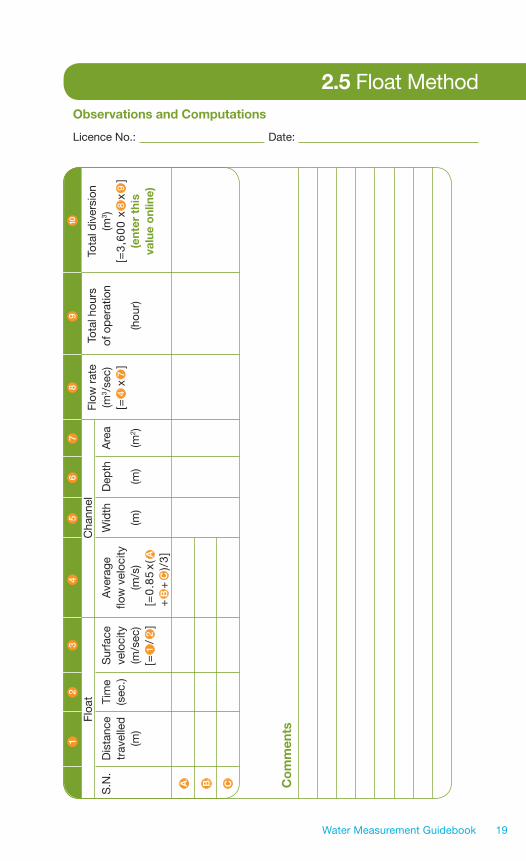
COMPUTING TOTAL DIVERSION 10. Determine the flow rate by multiplying values in column 4 and column 7 and record in column 8 . 11. Record total hours of operation in column 9 . 12. Determine the total diversion or usage by multiplying values in column 8 , 9 and 3,600 together and record in column 10 .
2.5 Float Method
Water Measurement Guidebook18
l
Unit Conversion From To Multiply By From To Multiply By
Acre-foot US gallon 325,851 Cubic foot Cubic metre 0.028
Acre-foot Imperial gallon 271, 328 Cubic foot US gallon 7.481
Acre-foot Cubic feet 43, 560 Cubic foot Imperial gallon 6.229
Acre-foot Cubic decametre 1.233 Hectares Acre 2.471
Cubic metre US gallon 264.172 Metre Foot 3.281
Cubic metre Imperial gallon 219.969 Inch Millimetre 25.4
Cubic metre Litre 1,000 Hour Second 3,600
Floa
t M
etho
d
Observations and Computations Licence No.: Date:
2.5 Float Method
Water Measurement Guidebook 19
Co
mm
ents
Fl
oat
C
hann
el
Flow
rat
e To
tal h
ours
To
tal d
iver
sion
S.N
. D
ista
nce
Tim
e
Sur
face
A
vera
ge
Wid
th
Dep
th
Are
a (m
3 /se
c)
of o
per
atio
n (m
3 )
tr
avel
led
(
sec.
) ve
loci
ty
flow
vel
ocity
[=4
x7
]
[=3
,60
0 x
8x
9]
(m)
(m/s
ec)
(m/s
) (m
) (m
) (m
2 )
(h
our)
(e
nter
thi
s
[=
1/
2]
[=0
.85
x( A
valu
e o
nlin
e)
+
B+
C)/
3]A
12
34
56
78
910
A B C

Water Measurement Guidebook20

An electronic copy of this guidebook is also available for download at http://environment.alberta.ca/1286.html
The head rod method can be used to measure the velocity of flowing water in a stream or channel. A head rod is a stainless steel ruler about 40 millimetres wide and one metre in length. A wooden ruler with a bevelled edge can also be used. The bottom end of the rod is in a small flat base. The width can vary within the normal range of ruler widths. This method involves measuring water depths at different points across the stream or channel section including the deepest part. The objective is to determine the head developed by a standing wave – see the diagram in the worksheet. The head is then used to calculate the flow of the stream following the instructions in the worksheet.
2.6 Head Rod Method
➜
Water Measurement Guidebook 21
Head R
od
Method

Equipment
1. A head rod or wooden ruler with beveled edge2. Measuring tape 3. Watch to record time
Procedure
MEASURING THE HEAD AND COMPUTING THE VELOCITY 1. Place the head rod in the waterway starting at a small distance from the edge. 2. Measure the depth in metres with the thin edge of the rod pointing towards flow direction and record in column 1 . 3. Rotate the head rod 90° so the flat side faces the direction of flow creating a standing wave. Measure new depth of water at the top of the standing wave and record in column 2 . 4. Subtract 1 from 2 to obtain the “head” and record in column 3 . 5. Repeat steps 1 to 3 five times at different points across the channel and record them in rows A through E . 6. Compute the average head in column 4 by adding up all heads in column 3 and dividing by 5 (number of measurements). 7. Compute the average velocity of flow in column 5 using the formula provided in that column.
MEASURING CHANNEL CROSS SECTIONAL AREA 8. Measure the average width of the channel section and record in column 6 . 9. Calculate the average depth of flow in column 7 by adding up column 1 and dividing by 5 (the total number of measurements). 10. Determine sectional area by multiplying values in column 6 by column 7 and record in column 8 .
COMPUTING TOTAL DIVERSION 11. Compute the flow rate by multiplying values in column 5 and column 8 and record in column 9 . 12. Record total hours of operation in column 10 . 13. Calculate the total diversion in column 11 by multiplying values in columns 9 , 10 and 3,600 together.
2.6 Head Rod Method
Water Measurement Guidebook22
depthD1
depthD2
headH = D2 - D1
Unit Conversion From To Multiply By From To Multiply By
Acre-foot US gallon 325,851 Cubic foot Cubic metre 0.028
Acre-foot Imperial gallon 271, 328 Cubic foot US gallon 7.481
Acre-foot Cubic feet 43, 560 Cubic foot Imperial gallon 6.229
Acre-foot Cubic decametre 1.233 Hectares Acre 2.471
Cubic metre US gallon 264.172 Metre Foot 3.281
Cubic metre Imperial gallon 219.969 Inch Millimetre 25.4
Cubic metre Litre 1,000 Hour Second 3,600
Hea
d R
od
Met
hod

Water Measurement Guidebook 23
Observations and Computations Licence No.: Date:
2.6 Head Rod Method
Co
mm
ents
S.N
. D
1 D
2 H
ead
A
vera
ge H
ead
Ave
rage
W
idth
D
epth
A
rea
Flow
rate
To
tal h
ours
D
iver
sion
(
m)
(m)
(m)
(m)
(m
) ve
loci
ty o
f flow
(m
)
(m)
(m2 )
(m3 /
sec)
of
ope
ratio
n (m
3 )
[=
2-
1]
from
col
umn
3
(m/s
ec)
fr
om c
olum
n
[=6
x7
] [=
5x
8]
(hou
r) [3
,600
x9
x10
]
[=(A
+B
+C
+
[=(1
9.62
x va
lue
[
=(A
+B
+C
+
(e
nter
thi
s
D
+E
)/5
] fro
m c
olum
n4
)0.5]
D+
E)/
5]
va
lue
onl
ine)
12
34
56
78
910
11
A B C D E
1

Water Measurement Guidebook24

An electronic copy of this guidebook is also available for download at http://environment.alberta.ca/1286.html
A weir is an overflow structure built in an open channel to measure flow rate. It can be temporarily installed for a short period or permanently for long term use. Depending on its construction, a weir can be classified as sharp-crested or broad-crested. Weirs can also be described as rectangular, trapezoidal or triangular based on the shape of the overflow opening. The trapezoidal weir is also known as Cipolletti and the triangular weir as V-notch. In using a weir you will need to make measurements of head. Head is the depth of water above the weir crest.
To use a weir you will first need a predetermined table of relationship between head (usually millimetres) and the rate of discharge (litres per second). You will need the services of a professional technical person to develop the table. Use of a weir consists of making head measurements and finding the corresponding flow rates in the table.
2.7 Weirs
➜
Water Measurement Guidebook 25
Weirs

Equipment
1. Installed weir2. Installed staff gauge 3. Rating table or weir equation 4. A watch to record time
Procedure
1. Read water level from the staff gauge and record in column 1 . 2. Determine the flow rate using the rating table and record in column 2 . 3. Record hours of operation/diversion in column 3 . 4. Multiply values in column 2 and 3 with 3,600 to obtain the total diversion.
Observations and Computations Licence No.: Date:
Comments
2.7 Weirs
Head on weir Flow rate Hours of operation Total diversion (m) (m3/s) (hours) (m3) [=3,600 x 2 x 3 ] (enter this value online)
1 2 3 4
Water Measurement Guidebook26
contracted rectangular
cipolletti contracted
suppressed rectangular
contracted triangular or v-notch
Unit Conversion From To Multiply By From To Multiply By
Acre-foot US gallon 325,851 Cubic foot Cubic metre 0.028
Acre-foot Imperial gallon 271, 328 Cubic foot US gallon 7.481
Acre-foot Cubic feet 43, 560 Cubic foot Imperial gallon 6.229
Acre-foot Cubic decametre 1.233 Hectares Acre 2.471
Cubic metre US gallon 264.172 Metre Foot 3.281
Cubic metre Imperial gallon 219.969 Inch Millimetre 25.4
Cubic metre Litre 1,000 Hour Second 3,600
Wei
rs

An electronic copy of this guidebook is also available for download at http://environment.alberta.ca/1286.html
The discharge rate (cubic metres per second) of a water pump is linked to the electricity consumed in pumping the water, pump efficiency and the total head lift. The total head lift is the elevation difference between the intake point and the discharge level.
The power is in kilowatt hours (kWh) and the total head is in metres. Typically, pump efficiencies vary between 75 to 80 percent.
The total diversion is determined by multiplying the discharge rate and the total pumping time (seconds).
Pow
er Consum
ption M
ethod
2.8 Power Consumption Method
Water Measurement Guidebook 27
➜

Procedure
1. Determine the energy consumed by your water pump from your power bill and enter the data in column 1 . 2. Determine the total head lift of your water system from the intake works to the point of discharge and record in column 2 . 3. Calculate the total diversion as shown in column 3 assuming pump efficiency of 75%
Observations and Computations Licence No.: Date:
Comments
2.8 Power Consumption Method
Energy consumed Total head lift Total diversion (kWh) (m) (m3) [( 1 x 276/( 2 )] (enter this value online)
1 2 3
Pow
er C
onsu
mpt
ion
Met
hod
Note, you may need assistance in making a distinction between power used for pumping and what may be attributable to other uses.
Water Measurement Guidebook28
Unit Conversion From To Multiply By From To Multiply By
Acre-foot US gallon 325,851 Cubic foot Cubic metre 0.028
Acre-foot Imperial gallon 271, 328 Cubic foot US gallon 7.481
Acre-foot Cubic feet 43, 560 Cubic foot Imperial gallon 6.229
Acre-foot Cubic decametre 1.233 Hectares Acre 2.471
Cubic metre US gallon 264.172 Metre Foot 3.281
Cubic metre Imperial gallon 219.969 Inch Millimetre 25.4
Cubic metre Litre 1,000 Hour Second 3,600

Water Measurement Guidebook 29
3.0 Glossary of Terms
Crest – the top of a weir, to which water must rise before passing over the structure
Discharge (Flow) – the volume of water that flows through a section of channel or pipe divided by time
Float – floating object for measuring the velocity of water
Head – relative rise in water level against standing object
Power – the rate of doing work; measured in watts
Pump efficiency – the relation between supplied and used energy in a system
Rating curve – relation between water level and flow rate
Velocity – distance divided by time
Hydrometric Technician Career Development Program, 1999. Water Survey of Canada
Measurement and Computation of Streamflow: 2005. Volume 1. Measurement of Stage and Discharge; Water Supply Paper 2175, U.S. Department of Interior, Geological Survey.
Waterwatch Australia National Technical Manual, 2002. Module 4 - Physical and Chemical Parameters, Waterwatch Australia Steering Committee, Environment Australia.
Water Measurement Manual. 2001. A Water Resources Technical Publication. U.S. Department of the Interior, Bureau of Reclamation. Revised Reprinted.
4.0 References
