measurement, processing and archiving of soil … environmental monitoring standards soil water...
TRANSCRIPT
National Environmental Monitoring Standards
Soil Water Measurement
Measurement, Processing and Archiving of
Soil Water Content Data
Version: 1.0
Date of Issue: June 2013
NEMS Soil Water Content Recording, Date of Issue: June 2013
NEMS Standards Documents
The following standards can be found at www.landandwater.co.nz.
National Quality Coding Schema
Safe Acquisition of Field Data In and Around Fresh Water Code of Practice
Dissolved Oxygen Recording Measurement, Processing and Archiving of Dissolved Oxygen Data
Open Channel Flow Measurement Measurement, Processing and Archiving of Open Channel Flow Data
Rainfall Recording Measurement, Processing and Archiving of Rainfall Intensity Data
Soil Water Measurement Measurement, Processing and Archiving of Soil Water Content Data
Turbidity Recording Measurement, Processing and Archiving of Turbidity Data.
Water Level Recording Measurement, Processing and Archiving of Water Level Data
Water Meter Data Acquisition of Electronic Data from Water Meters for Water Resource Management
Water Temperature Recording Measurement, Processing and Archiving of Water Temperature Data
Limitations
It is assumed that as a minimum the reader of these documents has undertaken industry based training and has a basic understanding of environmental monitoring techniques. Instructions for manufacturer specific instrumentation and methodologies are not included in this document.
The information contained in these NEMS documents relies upon material and data derived from a number of third party sources.
The documents do not relieve the user (or a person on whose behalf it is used) of any obligation or duty that might arise under any legislation, and any regulations and rules under those acts, covering the activities to which this document has been or is to be applied.
The information in this document is provided voluntarily and for information purposes only. Neither NEMS nor any organisation involved in the compilation of this document guarantee that the information is complete, current or correct and accepts no responsibility for unsuitable or inaccurate material that may be encountered.
Neither NEMS, nor any employee or agent of the Crown, nor any author of or contributor to this document shall be responsible or liable for any loss, damage, personal injury or death howsoever caused.
When implementing these standards, the following act, regulations and code of practice shall be complied with:
Health and Safety in Employment Act 1992
Health and Safety in Employment Regulations 1995
NEMS Safe Acquisition of Field Data In and Around Fresh Water, Code of Practice 2012

NEMS Soil Water Content Recording, Date of Issue: June 2013
National Environmental Monitoring Standards (NEMS)
The National Environmental Monitoring Standards steering group (NEMS) has prepared a series of environmental monitoring standards on authority from the Regional Chief Executive Officers (RCEO) and the Ministry for the Environment (MFE). The strategy that led to the development of these standards was established by Jeff Watson (Chairman) and Rob Christie (Project Director). The implementation of the strategy has been overseen by a steering group consisting of Jeff Watson, Rob Christie, Jochen Schmidt, Martin Doyle, Phil White, Mike Ede, Glenn Ellery, Lian Potter, Lucy Baker, Eddie Stead and David Payne.
The development of these standards involved consultation with regional and unitary councils across New Zealand, electricity generation industry representatives and the National Institute for Water and Atmospheric Research Ltd (NIWA). These agencies are responsible for the majority of hydrological and continuous environmental related measurements within New Zealand. It is recommended that these standards are adopted throughout New Zealand and all data collected be processed and quality coded appropriately. The degree of rigour in which the standard is applied, will depend on the quality of data sought.
The lead writer of this document was Maurice Duncan of the National Institute of Water and Atmospheric Research Ltd, with workgroup members, Anthony Davoren of HydroServices Ltd, Sam Carrick of Landcare Research, Glenn Ellery of Bay of Plenty Regional Council, Peter Stevenson of Otago Regional Council and Doug Stewart of Waikato Regional Council. The input of NEMS members into the development of this document is gratefully acknowledged; in particular the review undertaken by the NEMS Steering Group and non-technical editing by writer Chris Heath of Heath Research Services.
Funding
The project was funded by the following organisations:
Auckland Council
Bay of Plenty Regional Council
Contact Energy
Environment Canterbury Regional Council
Environment Southland
Genesis Energy
Greater Wellington Regional Council
Hawke’s Bay Regional Council
Horizons Regional Council
HydroServices
Landcare Research
Marlborough District Council
Meridian Energy
Mighty River Power
Ministry for the Environment
Ministry of Business, Innovation & Employment – Science & Innovation Group
National Institute of Water and Atmospheric Research Ltd (NIWA)
Northland Regional Council
Otago Regional Council
Taranaki Regional Council
Tasman District Council
West Coast Regional Council
Waikato Regional Council
Review
This document will be reviewed by the NEMS steering group in February 2014, and thereafter once every two years.
Signatories

NEMS Soil Water Content Recording, Date of Issue: June 2013
NEMS Soil Water Content Recording, Date of Issue: June 2013 Page | i
TABLE OF CONTENTS
Definitions ................................................................................................................................ ii
About this Standard ............................................................................................................. iv
The Standard – Soil Water Content Recording ................................................................v
Quality Codes – Soil Water Content Recording ............................................................ vii
1 Site Selection .............................................................................................. 1
1.2 Practical Controls ........................................................................................................2
1.3 Selection Criteria ..........................................................................................................3
2 Deployment ................................................................................................ 5
2.2 Dielectric Sensors .........................................................................................................7
2.3 Neutron Probe Sensors ............................................................................................. 10
3 Data Acquisition....................................................................................... 11
3.2 Calibration ................................................................................................................. 12
3.3 Soil Temperature Sensitivity ..................................................................................... 14
3.4 Soil Conductivity Sensitivity ..................................................................................... 15
4 Data Acquisition....................................................................................... 17
5 Data Processing & Preservation ............................................................ 19
5.2 Quality Codes ............................................................................................................ 20
5.3 Preservation of Record ............................................................................................ 21
5.4 Quality Assurance ..................................................................................................... 23
Annex A – List of Relevant Documents ...................................................... 25
Annex B – Soil Water Content Measurement – General Information .... 26
Annex C – Gravimetric Assessment of Soil Water Content ..................... 28
Annex D – Time Domain Reflectometry & Time Domain Travel ............. 30
Annex E – Neutron Probe Assessment ........................................................ 31
Annex F – Capacitance Assessment .......................................................... 32
NEMS Soil Water Content Recording, Date of Issue: June 2013 Page | ii
Definitions
absolute soil water content The weight of water per weight of soil, e.g., g water / g of soil.
bulk density The mass of the soil particles divided by the volume of soil and voids.
calibration The process of determining, checking, or rectifying the quantitative measurements of any instrument.
calibration range The range of soil water over which the calibration has been made. For the purposes of quality code assignment, the full (100%) calibration range is from permanent wilting point to saturation.
comments file A metadata file associated with the data file. The metadata provides relevant information about the site and data.
field capacity The water content in the soil after gravitational drainage from a saturated condition falls to a rate that is insignificant (i.e., drainage rate ≤ 1 mm / day). This is usually estimated in the field by measuring the soil water content two to three days after heavy rainfall, or by measuring the water content of soil cores in the laboratory after they have been equilibrated at a soil matric potential. In New Zealand the laboratory estimation of field capacity is measured at the nominal -10 kPa soil matric potential, but direct field measurements show that it can vary between -2 kPa and -30 kPa depending on soil texture.
gravimetric water content The mass soil water content relative to the mass of oven dry soil and has the units of kg, kg-1 or other consistent mass units.
matric potential A measure of how tightly water is held in the soil. Water is held more tightly in smaller pores as the potential decreases (becomes more negative).
metadata Information about the data that may describe the content, quality, condition and/or other characteristics of the data..
permanent wilting point The soil water content at which plants can no longer extract water from the soil and the plant is permanently wilted. The actual soil water potential at which permanent wilting point occurs varies between plant types, but in New Zealand it is nominally estimated in the laboratory by measuring the soil water content at -1500 kPa soil water potential.
profile available water (PAW) The amount of water that a soil can hold for plant growth. It is defined as the water held in the soil profile between field capacity and permanent wilting point in a defined depth of soil. This can be expressed as in-depth units as millimetres of soil water over a defined depth increment, e.g., PAW 200 mm.
QC Abbreviation for quality code. For example, a quality code of 600 may be referred to as QC 600
quality codes An overlying set of associated information that provides the end user with information about the quality of the data.
raw data Data sourced directly from a data logger.
recording agency The agency responsible for carrying out the observations.
NEMS Soil Water Content Recording, Date of Issue: June 2013 Page | iii
relative soil water content The soil water content relative to the soil water holding capacity (per cent of water holding capacity). This can refer to uncalibrated data where only the relative changes in soil moisture content are of interest.
resolution The increment that is measurable by a scientific instrument.
saturation The soil water state when all the soil pores are filled with water.
site The geographical location of the soil water monitoring station.
soil horizon A distinct layer of soil that has a unique combination of soil attributes, different to the soil immediately above and below.
soil profile The combination of soil horizons to a defined depth of interest. In soil survey this is typically to 1 m depth.
soil water content The mass or volume of water in the soil, typically expressed as a dimensionless percentage.
S Map Web-based soil maps on a site hosted by Landcare Research. http://smap.landcareresearch.co.nz/home
station The collective term for soil water instruments at a particular site.
stationarity of record The quality of a process in which the statistical parameters of the process do not change with time. Stationarity of record is maintained when variability, of the parameter being measured, is only caused by the natural processes associated with the parameter. Stationarity of record ceases when variability is caused or affected by other processes, e.g., changing the location of a neutron probe access tube or changing the type or manufacturer of a sensor.
uncertainty A measure of accuracy of the readings. Express as a range of error at a stated probability.
validation A check to determine if the device or procedure conforms to specifications.
volumetric water content The volume of water per bulk volume of soil.

NEMS Soil Water Content Recording, Date of Issue: June 2013 Page | iv
About this Standard
Introduction
Soil water content information is collected from a variety of soil types and is used for a variety of purposes including comparative regional and national assessments, irrigation and effluent application scheduling. Continuous measurements have allowed scientists a deeper understanding of soil water content dynamics and in particular the dynamics of soil saturation and the rapid drainage that occurs when rain stops. This document outlines how to measure and the standards for absolute soil moisture. Key to planning, maintaining and recording soil water is the understanding of and catering for stationarity.
A soil water content record can be used to estimate field capacity and permanent wilting point soil water content levels. Measurements used for this purpose requires a good understanding of the relationship between soil water contents and soil water use by plants.
It is important to understand the range of uses to which the data can be put, and ensure that data collected for one purpose can be used as widely as possible in the future.
Objective
The objective of this standard is to ensure in situ measurement of soil water content is consistently gathered, processed and archived over time and across New Zealand and is suitable for ‘at site’ and comparative analysis.
Scope
The standard covers gravimetric, dielectric, heat-pulse and neutron probe soil water content sensors and all processes associated with:
site selection
deployment
calibration
the acquisition of soil water data
data processing, and
quality assurance (QA) that is undertaken prior to archiving the data.
Note: Soil water content can be measured gravimetrically and converted to volumetric by using bulk density measurements. For more information, see ‘Annex C – Gravimetric Assessment of Soil Water Content’
Exclusion
The standard does not apply to:
measurements of soil matric potential, nor
hand-held or portable sensors sampling random sites.
NEMS Soil Water Content Recording, Date of Issue: June 2013 Page | v
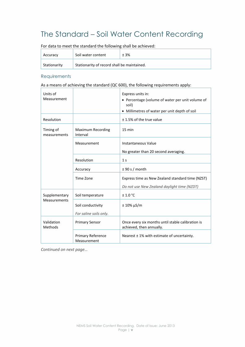
The Standard – Soil Water Content Recording
For data to meet the standard the following shall be achieved:
Accuracy Soil water content ± 3%
Stationarity Stationarity of record shall be maintained.
Requirements
As a means of achieving the standard (QC 600), the following requirements apply:
Units of Measurement
Express units in:
Percentage (volume of water per unit volume of soil)
Millimetres of water per unit depth of soil
Resolution ± 1.5% of the true value
Timing of measurements
Maximum Recording Interval
15 min
Measurement Instantaneous Value
No greater than 20 second averaging.
Resolution 1 s
Accuracy ± 90 s / month
Time Zone Express time as New Zealand standard time (NZST)
Do not use New Zealand daylight time (NZDT)
Supplementary Measurements
Soil temperature ± 1.0 °C
Soil conductivity
For saline soils only.
± 10% µS/m
Validation Methods
Primary Sensor Once every six months until stable calibration is achieved, then annually.
Primary Reference Measurement
Nearest ± 1% with estimate of uncertainty.
Continued on next page…

NEMS Soil Water Content Recording, Date of Issue: June 2013 Page | vi
Requirements (continued)
Calibration Frequency Annually
Methods Electronic instruments: Calibrate against gravimetrically assessed samples or neutron probe.
Neutron probes: Calibrate against stable water content materials in drums. Calibrate the drums using a neutron probe that has been calibrated with gravimetrically assessed samples
Metadata Scope Metadata shall be recorded for all measurements.
Quality Assurance
Quality assurance requirements are under development.
Processing of Data
All changes shall be documented.
The application of calibrations shall be documented.
All data shall be quality coded as per Quality Flowchart.
The following table summarises best practice and is not required for QC 600:
Validation Methods
Inspection of Recording Installations
Perform at least annual inspections to ensure calibration remains stable
Archiving Original and Final Records
File, archive indefinitely, and back up regularly:
Raw and processed records
Primary reference data
Supplementary measurements
Validation checks
Calibration results
Metadata
Auditing Quality assurance requirements are under development.

NEMS Soil Water Content Recording, Date of Issue: June 2013 Page | vii
Quality Codes – Soil Water Content Recording
All data shall be quality coded in accordance with the National Quality Coding Schema. The schema permits valid comparisons within a data series and across multiple data series. Use the following flowchart to assign quality codes to each time-step.

NEMS Soil Water Content Recording, Date of Issue: June 2013 Page | i
The calibration range refers to the range of soil water over which the calibration has been made.
If the calibration range is… … assign quality code:
< 70% of the range between permanent wilting point and field capacity
QC 400
70% to 90% of the range between permanent wilting point and field capacity
QC 500
> 90% of the range between permanent wilting point and field capacity
QC 600

NEMS Soil Water Content Recording, Date of Issue: June 2013
Page | 1
1 Site Selection
This section contains information on the factors to be considered when selecting a site for deployment of soil water content sensors.
1.1.1 Stationarity
The usefulness of a soil water record is dependent upon it having been collected at the same location using similar recording standards over the entire period of record.
Stationarity of record:
is maintained when variability of the parameter being measured is only caused by the natural processes associated with the parameter, and
ceases when variability is caused or affected by other processes, e.g., moving the station or changing the type of instrument.
Without stationarity, a data record cannot be analysed for changes over time (such as climate change). While the accuracy of collection processes may change, it is critical that the methods and instruments used to collect soil water content records remain without bias over the lifetime of the record. For example, if a sensor is replaced by another brand of sensor it is possible that the dynamic response of the soil water content will change.
Because the methods of collecting continuous environmental data do change over time, an external reference should always be used against which the continuous data can be checked. In the case of soil water content, this is either gravimetric measurement of soil water content or neutron probe measurement where the probe has been calibrated against gravimetric measurements or standardised drums of material with a constant hydrogen ion content.
It is notable that many of the early soil water content records can be directly compared to records collected today despite changes in the agencies responsible for collecting the data. This is a direct result of well thought out practices carried out by the pioneers of water content measurement in NZ. The basic principles applied by these pioneers can still be used today, along with refinements and new practises developed along the way.

NEMS Soil Water Content Recording, Date of Issue: June 2013
Page | 2
1.2 Practical Controls
1.2.1 Site Access
Site access shall be secure and safe for the complete period of deployment.
A long term access agreement with any landowners whose land must be crossed to gain access to the site is recommended.
1.2.2 Safety
Hazards (for observers, the public, livestock, and wildlife) related to the location and the measurement activity shall be identified and mitigated.
1.2.3 Hazard Review
On selection of a final site, a hazard review shall be carried out in accordance with relevant guidelines or best practise.
The potential for human activity affecting the measurement, e.g., vandalism, shall be minimised.
NEMS Soil Water Content Recording, Date of Issue: June 2013
Page | 3
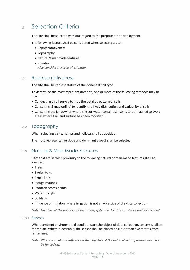
1.3 Selection Criteria
The site shall be selected with due regard to the purpose of the deployment.
The following factors shall be considered when selecting a site:
Representativeness
Topography
Natural & manmade features
Irrigation Also consider the type of irrigation.
1.3.1 Representativeness
The site shall be representative of the dominant soil type.
To determine the most representative site, one or more of the following methods may be used:
Conducting a soil survey to map the detailed pattern of soils.
Consulting ‘S-map online’ to identify the likely distribution and variability of soils.
Consulting the landowner where the soil water content sensor is to be installed to avoid areas where the land surface has been modified.
1.3.2 Topography
When selecting a site, humps and hollows shall be avoided.
The most representative slope and dominant aspect shall be selected.
1.3.3 Natural & Man-Made Features
Sites that are in close proximity to the following natural or man-made features shall be avoided:
Trees
Shelterbelts
Fence lines
Plough mounds
Paddock access points
Water troughs
Buildings
Influence of irrigators where irrigation is not an objective of the data collection
Note: The third of the paddock closest to any gate used for dairy pastures shall be avoided.
1.3.3.1 Fences
Where ambient environmental conditions are the object of data collection, sensors shall be fenced off. Where practicable, the sensor shall be placed no closer than five metres from fence lines.
Note: Where agricultural influence is the objective of the data collection, sensors need not be fenced off.
NEMS Soil Water Content Recording, Date of Issue: June 2013
Page | 4
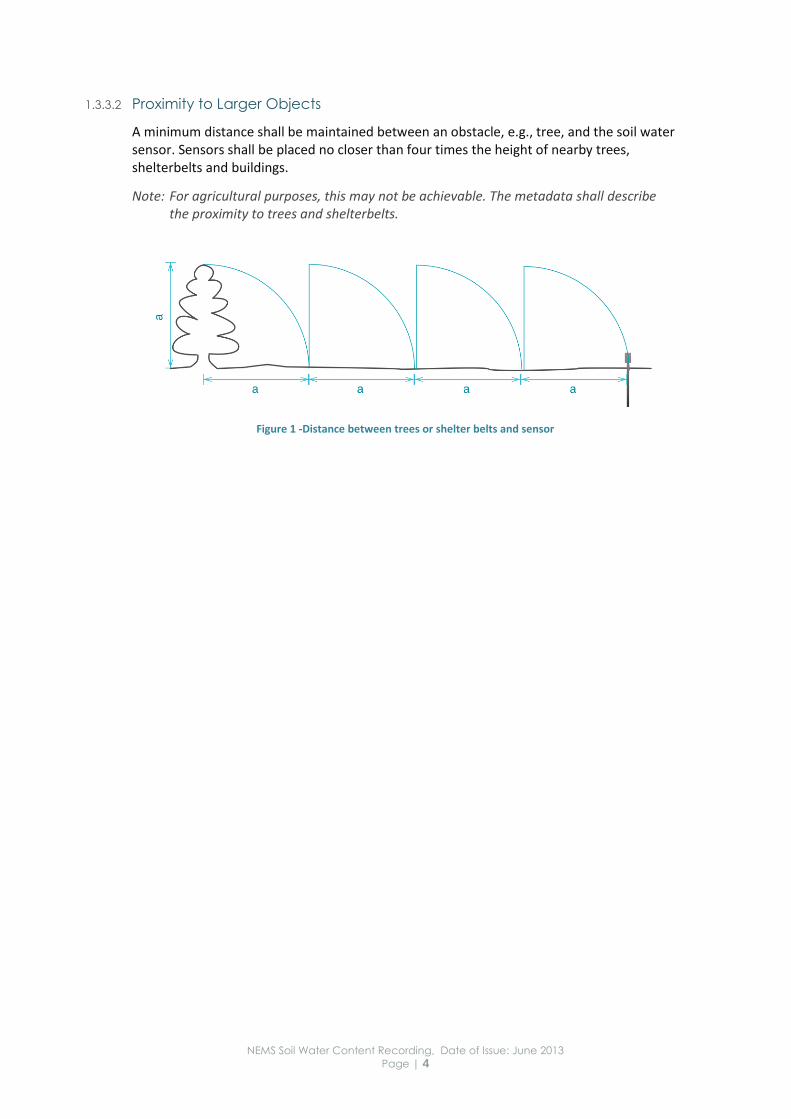
1.3.3.2 Proximity to Larger Objects
A minimum distance shall be maintained between an obstacle, e.g., tree, and the soil water sensor. Sensors shall be placed no closer than four times the height of nearby trees, shelterbelts and buildings.
Note: For agricultural purposes, this may not be achievable. The metadata shall describe the proximity to trees and shelterbelts.
Figure 1 -Distance between trees or shelter belts and sensor
NEMS Soil Water Content Recording, Date of Issue: June 2013
Page | 5
2 Deployment
2.1.1 In this Section
This section contains standards relating to the deployment of the following sensors that are used to measure soil water content:
Dielectric Sensors
Neutron Probe Sensors
2.1.2 Locating Sensors
The location of deployed sensors may be marked using, for example:
sprung stakes
pegs
fibreglass rods, or
other easily identified markers.
Triangulation or GPS can be used to determine the approximate location of a sensor when physical markers are not appropriate.
When deploying buried sensors, a metal rod shall be placed approximately 100 mm from each sensor. However, in no case shall anything be placed within the sensor measurement volume.
Note: Triangulation and GPS may be used to record and locate the approximate location of a sensor, however, metal rods are required so that the precise location of the sensor can be determined with a metal detector.
2.1.3 Complementary Measurements
Where relevant, any or all of the following measurements may be taken:
Rainfall intensity For more information refer to: 'NEMS Rainfall Recording – Measurement Processing and Archiving of Rainfall Intensity Data’.
Soil temperature
Vegetative cover Crop type, stage, height and an assessment of percentage ground cover should be recorded at each site inspection.
Soil profile This should be described and rooting depth recorded during the deployment of the sensor.
2.1.3.1 Soil Temperature
If required, soil temperature measurements shall be recorded:
for point sensors, at the same depth as the soil water sensor
for ribbon sensors, 100 mm (min) below the soil surface
at the same time as recording soil water, and
to a resolution of ± 0.1 °C.

NEMS Soil Water Content Recording, Date of Issue: June 2013
Page | 6
Note: Recording both soil water and soil temperature at the same time, assists with temperature correction of the record and is imperative for temperature correction of dielectric soil water measurements. Soil temperature is a critical parameter for plant growth.

NEMS Soil Water Content Recording, Date of Issue: June 2013
Page | 7
2.2 Dielectric Sensors
2.2.1 Background
There are two main types of dielectric sensor. These are:
dielectric ribbon sensors, and
dielectric probe sensors. Dielectric probe sensors can have flat or needle-like probes.
2.2.2 Installation Method
Dielectric sensors shall be installed by:
excavating a trench and inserting one side of the ribbon sensor against one trench wall and packing soil against the other side of the sensor, or,
digging a pit and inserting the probe sensor into the pit face at standard depths, or
pushing probe sensors with needles vertically downwards into the soil surface.
Once deployed, dielectric sensors shall not be disturbed.
The quality codes apply to all types of sensor.
2.2.3 Deployment Depths
2.2.3.1 Dielectric Ribbon Sensors
For regional and nationally consistent data collection, the dielectric ribbon shall be installed over a standard depth range of 100 mm to 400 mm. Dielectric ribbon sensors shall not be installed to cross soil horizon boundaries where there is strongly contrasting soil density, texture or structure.
2.2.3.2 Dielectric Sensors
Standard deployment depths for dielectric sensors are:
100 mm
300 mm, and
every 200 mm thereafter until there is a sensor below the root zone, or
below the root zone ( > 400 mm ).
Shallower depths normally have the highest priority because that is where root activity is greatest and where there is the most change in soil water content.
The dielectric ribbon sensor shall be installed at least 50 mm above any strongly contrasting soil transition.
The depth of the sensor and soil profile shall be recorded with the permanent site records.
2.2.4 Deployment of Flat Sensors
Dielectric sensors shall be installed with the flat surface vertical.

NEMS Soil Water Content Recording, Date of Issue: June 2013
Page | 8
2.2.5 Deployment on Sloping Terrain
Dielectric sensors installed on sloping terrain shall have the long dimension of the sensor up and down slope.
Dielectric sensors shall be placed on the uphill side of soil pits.
2.2.6 Trapped Water
Dielectric sensors shall not be deployed where water would be trapped against the sensor.
2.2.7 Pit Deployment of Dielectric Probe Sensors
Cables for sensors deployed in pits are to approach the sensor from below the sensor (Figure 2).
The probe shall be horizontal or sloping slightly upwards (Figure 2).
A short hole shall be made in the pit wall before inserting the sensor, to allow the sensor probes to be located away from the pit wall.
Under-size pilot holes may be made for dielectric sensors with needles.
Only probe sensors that can be deployed into undisturbed soil shall be installed in subsoil horizons.
Figure 2 – Cable for dielectric probe sensors deployed in pits are to approach the sensor from below. The sensors shall be inserted into small hollows made into the pit face.
Illustrator: Chris Heath

NEMS Soil Water Content Recording, Date of Issue: June 2013
Page | 9
2.2.8 Trench Deployment of Dielectric Ribbon Sensors
Dielectric ribbon sensors may be installed within a trench where the ribbon is sloping with respect to the soil surface.
Figure 3 – Trench Deployment
Note: Dielectric ribbon sensors placed in a sloping trench integrate soil water over the depth from 50 mm above the highest part of the ribbon to 50 mm below the lowest part of the ribbon.
The top of the electronics end of ribbon shall be placed 100 mm below the surface. The other end of the ribbon shall be placed at the desired depth below the surface.
2.2.9 Soil Disturbance
2.2.9.1 Dielectric Ribbon Sensors
When deploying dielectric ribbon sensors in a trench first remove the turf. When the sensor has been installed return the turf to its original location, preserving, as far as practicable, the natural lithology.
When deploying dielectric ribbon sensors, where practicable, disturbed deployment shall be confined to the layers above the subsoil horizon.
Note: Following a disturbance, the soil pore network of subsoil horizons is unlikely to have the same capacity for dynamic recovery as the topsoil horizon so dielectric ribbon sensors should not be deployed into disturbed subsoil.
When repacking the soil around a dielectric ribbon sensor:
the use of slurries or soil of a different texture to the soil profile shall be avoided, and
stones shall not be removed from the soil.
Where the soil is disturbed, e.g., for the deployment of a ribbon sensor, the soil shall be repacked around the sensor from the soil horizons in the same sequence they were removed.
Important: Accurate measurements may not be obtainable until the soil has had time to settle around the sensor. Settling may take a few wetting and drying cycles and may take 1 to 2 years
2.2.10 Annual Checks
When excavations have been made to install sensors, annual checks shall be performed and any settling of the surface, where practicable, shall be returned to its natural state.
Note: Annual checks ensure the soil surface does not result in ponding of surface water and therefore cause measurement bias.
100 mm minimum
400 mm
NEMS Soil Water Content Recording, Date of Issue: June 2013
Page | 10
2.3 Neutron Probe Sensors
2.3.1 Safety Requirements
Users of neutron probe soil water sensors shall work under the supervision of a person licensed by the Ministry of Health to use neutron density meters. There is no hazard if the instrument is used as per manufacturer instructions. However, there are procedures to be followed for the labelling, transport and storage of instruments, logging of the instrument location and in case of damage to the instrument. The organisation using the probe must have a Radiations Safety Plan.
2.3.2 Access Tubes
Neutron probe sensors require an access tube (normally aluminium) and the sensor is lowered down the access tube from the surface.
Neutron probe access tubes shall be driven into undersize holes.
Neutron Probe access tubes normally extend to below the rooting depth so excess irrigation can be detected.
The access tube shall be fitted with a cap to prevent it filling with water.
The neutron probe access tube shall have a tapered end tip.
Note: The end tip helps guide the tube when it is being driven into the soil and prevents ground water entering via the bottom of the tube.
2.3.3 Measurement Depths
The first measurement shall be taken at least 150 mm from the soil surface.
Note: Measurements taken at depths shallower than 150mm may be biased low because the neutrons can escape above the soil surface and are therefore not available to be reflected back to the instrument for detection.
The second measurement is typically taken at 300 mm from the soil surface, with subsequent measurements at 200 mm intervals until there is measurement location below the root zone.
Note: The cable used for lowering the neutron source down the access tube is normally provided with stops so the source is lowered to exactly the same depths for successive measurements.
2.3.4 Measurement Duration
The measurement duration at each depth is dependent on the neutron source strength and is normally between 15 second and 30 seconds.
Note: The accuracy of measurements can be increased by increasing the measurement time.
NEMS Soil Water Content Recording, Date of Issue: June 2013
Page | 11
3 Data Acquisition
3.1.1 In this Section
This section contains information on the acquisition of soil water data. It covers:
calibration
soil temperature sensitivity, and
soil conductivity sensitivity.

NEMS Soil Water Content Recording, Date of Issue: June 2013
Page | 12
3.2 Calibration
If absolute measurements are required, all soil water content sensors shall be field calibrated.
Gravimetric measurement of soil water content is the reference method for calibration for all soil water content sensors. However, gravimetric assessment is time consuming and is destructive because the soil is removed for measurement. Thus secondary methods are often adopted for instrument calibration.
Note: Annex C details how samples are taken and analysed for gravimetric assessments of soil water content.
Where gravimetric calibration is not practicable, dielectric sensors may be calibrated using neutron probes.
3.2.1 Dielectric Soil Water Sensors
To assign quality code QC 600, calibration of the dielectric soil water sensor is required.
Dielectric soil water sensors are sensitive to clay type and content, organic matter content, temperature and soil conductivity, so field calibration is essential.
Dielectric sensors shall be field calibrated:
immediately after deployment, and
annually.
3.2.1.1 Gravimetric Calibration of Dielectric Sensors
Where practicable, soil water shall be sampled and analysed gravimetrically.
Gravimetric calibration of dielectric sensors is achieved by taking a soil sample (See Annex C) from the same part of the soil profile as the sensor is sampling close to, but not in the within the dielectric sensor’s measurement volume.
Soil samples shall be taken at different soil water contents. This ensures as wide a range of soil water content as possible.
The number of soil samples taken depends on the linearity of the calibration relationship and the need to cover the soil water content range. Three is the minimum number for a linear relationship.
Note: For gravimetric calibration of sensors see Annex C.
3.2.1.2 Neutron Probe Calibration of Dielectric Sensors
The neutron probe access tube shall be placed as close to the sensor as practicable (nominally 100 mm), but not within the dielectric sensor’s measurement volume.
For ribbon sensors, install neutron probe access tubes 100 mm (nominal) from each end of the ribbon. A neutron probe access tube half way along the ribbon is also recommended (nominal clearance 100 mm).
Note: If access tubes (for neutron probes) are to be used for calibrating dielectric sensors, they should be installed immediately after deploying the dielectric sensors so they can

NEMS Soil Water Content Recording, Date of Issue: June 2013
Page | 13
be properly located in relation to the sensor. Subsequently the tubes and sensor can be located using a metal detector.
3.2.2 Neutron Probe Sensors
Neutron probes shall be field calibrated.
3.2.2.1 Gravimetric Calibration of Neutron Probe Sensors
Where practicable, soil water content shall be sampled and analysed gravimetrically.
3.2.2.2 Calibration of Neutron Probe Sensors using Stable Reference Standards
Neutron probes may be subsequently calibrated using water stable reference standards, for example separate sealed drums containing:
water
wax
plastic
concrete
Calibration checks shall be repeated annually in the same reference drums.
3.2.2.3 Accuracy of Calibration for Neutron Probe Sensors using Stable Reference
Standards
The calibration shall be accurate to ± 0.5%.
Note: After the application of the calibration, measurements taken in the calibration drums should be within 0.5% of the value for the water content of the drums.
NEMS Soil Water Content Recording, Date of Issue: June 2013
Page | 14
3.3 Soil Temperature Sensitivity
Time domain reflectivity and dielectric soil water content sensors are sensitive to soil temperature changes and the level of soil conductivity.
Where practicable, the soil water content sensor shall also:
measure soil temperature
be corrected for temperature, or
operate at a frequency where temperature effects are minor.

NEMS Soil Water Content Recording, Date of Issue: June 2013
Page | 15
3.4 Soil Conductivity Sensitivity
Time domain reflectivity and dielectric soil water content sensors are sensitive to soil conductivity changes.
Where practicable, the soil water content sensor shall also:
measure soil conductivity
have in-built soil conductivity correction
not be unduly sensitive to soil conductivity, or
operate at a frequency where conductivity effects are minor.
If the soil water content sensor does not have any conductivity related functionality (as described above), then the manufacturer’s conductivity correction method shall be followed.
Note: High soil conductivity can be an issue in soils that receive wastewater or in areas with low rainfall such as parts of Central Otago.

NEMS Soil Water Content Recording, Date of Issue: June 2013
Page | 16
NEMS Soil Water Content Recording, Date of Issue: June 2013
Page | 17
4 Data Acquisition
4.1.1 In this Section
This section contains information on data collection, units, frequency of measurement, and precision.
4.1.2 Units
Sensors shall have settings that can easily be converted to:
percentage ‘volume of water per unit volume of soil’, and/or
millimetres of water per unit depth of soil.
Both units shall be recorded to one decimal place.
The date and time of each reading shall be recorded.
4.1.3 Data Collection Frequency
4.1.3.1 Dielectric Sensors
Dielectric sensors can measure soil water content at small time intervals (seconds or minutes).
A maximum of one hour between recorded measurements is recommended.
4.1.3.2 Portable Instruments that use Access Tubes
A maximum of seven days between recorded measurements is recommended.
Note: A neutron probe is a portable instrument.
4.1.4 Precision
All instruments can give precise measurements, i.e., repeatable measurements that differ by less than ± 1 %.
Note: Unless the instruments have been calibrated, either in the field or the laboratory, they may not be accurate. Without calibration, the instruments do not provide the absolute soil water content. For more information, refer to: ‘IAEA (2008), Appendix A’.

NEMS Soil Water Content Recording, Date of Issue: June 2013
Page | 18
NEMS Soil Water Content Recording, Date of Issue: June 2013
Page | 19
5 Data Processing & Preservation
5.1.1 In this Section
This section contains information on the processing of soil water data.
5.1.2 Original Record
Soil water (conductivity and temperature) as logged, shall be kept as the original record.
This record may be calibrated and temperature and/or conductivity corrected and archived separately.
5.1.2.1 Excavations
Where excavations are required for sensor installation, the following information shall be maintained with the site’s original record:
Photos of the site and soil pit
Bulk density Soil samples of each significant change in soil lithology should be obtained and the bulk density determined.
5.1.2.2 When Calibrations Change
If the calibration changes, the new calibration will be applied gradually (ramped) over the interval between calibrations, unless there is an obvious reason and time to apply a step correction.
Note: In the case of dielectric ribbon sensors that may take time to settle, the readings will be given a lower quality code, until the calibration has stabilised.
5.1.2.3 Missing Record
Any gaps that occur in a soil water record shall be filled to the best time resolution practical. The maximum time resolution shall be daily for electronic sensors.
5.1.2.4 Acceptable Percentage of Missing Record
Note: Robust field procedures and good quality instrumentation should result in no more than 2% missing record occurring in any one site-year of record across an organisations network. If there is more than 2% missing record occurs at a site over any rolling 12-month period, the underlying cause should be addressed.
5.1.2.5 Filling Missing Record
Missing records shall be filled on a case-by-case basis.
5.1.2.6 Replacement Sensors
Information on replacement sensors shall be recorded in the metadata.
Replacement sensors for sites meeting the same selection criteria shall retain the site number of the original site.

NEMS Soil Water Content Recording, Date of Issue: June 2013
Page | 20
5.2 Quality Codes
All data shall be quality coded in accordance with the National Quality Coding Schema. The schema permits valid comparisons within a data series and across multiple data series. Use the following flowchart to assign quality codes to each time-step.
Figure 4 – Soil Water Data Quality Codes.
NEMS Soil Water Content Recording, Date of Issue: June 2013
Page | 21
5.3 Preservation of Record
5.3.1 Performance
The following data shall be archived and retained indefinitely:
Final checked and verified data – whether primary or backup
Unedited raw primary and backup data
Associated metadata, including;
data comments
site details
recording accuracy and resolution
site / station inspections
equipment calibration history, and
any other factors affecting data quality.
All original records shall be retained indefinitely by the recording agency.
Note: The original raw data may be required at a later date, should the archive data:
be found to be in error
becomes corrupted, or
be lost.
5.3.2 Data Archiving
The archiving procedures, policies, and systems of the archiving body shall consider:
future data format changes
off-site duplication of records, and
disaster recovery.
5.3.3 Metadata – Site Details
Adequate mechanisms shall be put in place to store all relevant site related metadata with the actual data records including, but not limited to:
site purpose
recording agency/ies
site location and photographs For example, GPS coordinates and triangulation information and/or location of metal rods or neutron access tubes in relation to the sensor. Photographs of site layout and photographs of soil profiles where available.
site name and past and present aliases
names and/or indices of relevant environmental features For example: ground cover – pasture or crop type.
start and end date of site and record Recorded using New Zealand standard time (NZST)
related sites and records
reference to the standard used

NEMS Soil Water Content Recording, Date of Issue: June 2013
Page | 22
influence of irrigation
the presence and type of fencing
S-map or soil survey description, or detailed farm soil map.
a description of the soil profile including depth, texture and drainage characteristics, e.g., poorly drained, well drained, excessively drained etc.
aspect
topography
current cover / land use, e.g., arable, dairy.
land use history, and For example: Has the field been border dyked? Is it ex forestry? Has there been landscaping to accommodate irrigation and cropping, or is it unknown?
missing record information.
5.3.3.1 Metadata – Other Details
Adequate mechanisms shall be put in place to store other relevant site related metadata including:
sensor details Sensor type, make and serial number
original format details
calibration records Preferably through an agency instrument / asset management system.
a record of the manufacturers calibration equation
a record of how soil water calibrations were obtained and applied, or whether no correction was made.
a record of the manufacturer’s or field calibration,
a record of how temperature corrections were applied, or whether no correction was made
a record of how conductivity corrections were applied, or whether no correction was made.
any relevant comments in document vocabularies that future users will understand, and For example: Terms shall be defined and instrument types referred to; not brands.
information about:
legal requirements
confidentiality agreements
intellectual property, and
any other restrictions related to data access.
Note: Most of this metadata shall be gathered during deployment. Correction/calibration information can only be recorded once enough calibration data has been gathered.

NEMS Soil Water Content Recording, Date of Issue: June 2013
Page | 23
5.4 Quality Assurance
All agencies shall implement a standard methodology for data audit and review:
Note: This is to ensure standardisation of data-sets that enable meaningful analyses and comparison of water content data within regions, across regions and nationally.
5.4.1 Audit Cycle
Quality assurance procedures shall include an audit of the data:
at a frequency appropriate to the organisation’s users and user’s needs, or
as defined by the organisation’s quality management systems documentation or documented procedures.
This work shall be undertaken by a suitably qualified and experienced practitioner.
Unaudited data that is released for use shall be identified as being unaudited.
Sites other than those under review may be included in the audit, including reliable records from sites operated by other agencies.
5.4.2 Minimum Audit Report Requirements
As a minimum, analyses and information required for an audit report for water content sites shall cover:
Site details
Comments and quality coding
Data plots
5.4.2.1 Site Details
A location map, with instrument locations identified shall be included in the report.
The detail shall include:
associated rainfall or climate sites
comparative soil water recording sites
the period of record covered
the site name and number
map or GPS reference
altitude, and
instrument type.
5.4.2.2 Comments and Quality Coding
The following shall be included in the audit report:
For each site being reviewed, a copy of the filed comments for the total record period
A copy of the quality codes of all the data being audited

NEMS Soil Water Content Recording, Date of Issue: June 2013
Page | 24
5.4.2.3 Data Plots
The following shall be included in the audit report:
Plot of the soil water content.
Over plot of daily rainfall and irrigation where applicable.
5.4.2.4 Report Outputs
Any one of the following report outputs is acceptable:
Hard copy report.
Electronic report.
An electronic document that only identifies which periods of record have passed audit.
5.4.2.5 Audit Certification
The completed audit shall contain the:
name and signature of the auditor, and
date that the audit was completed.

NEMS Soil Water Content Recording, Date of Issue: June 2013
Page | 25
Annex A – List of Relevant Documents
Aqualinc Research. A farmer’s guide to soil moisture monitoring. http://www.myirrigation.info/_guides/Farmers Guide To Soil Moisture.pdf 12 p.
International Atomic Energy Agency, VIENNA, 2008. Field Estimation of Soil Water Content: A Practical Guide to Methods, Instrumentation and Sensor Technology. IAEA-TCS-30 Vienna. ISSN 1018–5518.
World Meteorological Office. 2008. Chapter 11. Measurement of Soil Moisture. 11 pages. IN: WMO Guide to Meteorological instruments and methods of observation WMO-No. 8 (Seventh edition) available at: http://www.wmo.int/pages/prog/www/IMOP/CIMO-Guide.html
Jarman, P. 2001. Irrigation New Zealand Manual. http://www.irrigationnz.co.nz/publications/irrigation-nz-manual/.

NEMS Soil Water Content Recording, Date of Issue: June 2013
Page | 26
Annex B – Soil Water Content
Measurement – General Information
Acknowledgement
The information in this section and those following is adapted from the Irrigation New Zealand Manual.
Overview of Different Soil Water Measurement Methods
Gravimetric
The gravimetric method is a direct method of manual sampling and oven drying (traditional laboratory method).
Soil Suction
Soil suction measures how hard it is for a plant to abstract water from the soil, Examples: tensiometers, irrometer.
Electrical Resistance
Electrodes connected to a porous block. The electrical current through the block changes with moisture content.
Examples: Gypsum Block, Watermark.
Capacitance
The capacitance of the soil changes with water content. Examples: WTL probe, Enviroscan, Decagon.
Neutron Thermalisation
Water scatters and slows down the movement of neutrons, which can be detected, Example: Troxler, CPN HydroProbe.
TDR (Time Domain Reflectometry), TDT, (Time Domain Travel)
This measures the speed of propagation of a signal that depends on the dielectric constant of the soil.
Example: Trase, Aqualflex, Acclima.
Thermal Dissipation
This measures heat dissipation in soil, which depends on water content.
Example: AquaSensor,
Soil Thermocouple Psychrometers
Sensors mounted in ceramic cups that measure the energy status of the soil solution.
These sensors are not common.

NEMS Soil Water Content Recording, Date of Issue: June 2013
Page | 27
Table 1 – A comparison of the different types of instruments that measure soil water content. Modified from: Campbell Scientific Inc. Decagon Devices.
Neutron Probe TDR TDT Capacitance
Accuracy +/- 3 % Increases with calibration
+/- 3 % Increases with calibration
+/- 3 % Increases with calibration
+/- 3 % Increases with calibration
Temperature
Sensitivity
Insensitive Soil dependent, can be significant
Soil dependent, can be significant
Soil/sensor dependent, can be significant
Salinity
Sensitivity
Insensitive Low levels: low High levels: fails
Low levels: low High levels: fails
Low levels: low High levels: low to high, probe specific
Sphere of
influence
radius
Dry: 50 cm
Wet: 10 cm
0.5-2cm 0.5 cm 0.5-2cm
Install into
undisturbed
soil?
Yes Yes No Yes

NEMS Soil Water Content Recording, Date of Issue: June 2013
Page | 28
Annex C – Gravimetric Assessment of Soil
Water Content
Gravimetric measurement of soil water content is the reference method for calibration for all soil water sensors.
Advantages
Gravimetric assessment is:
accurate
relatively simple, and
directly measures the amount of soil water.
Disadvantages:
Gravimetric assessment:
is destructive because the soil is removed for measurement
requires laboratory and soil sampling tools
takes at least 24 hours to get results
requires bulk density measurements to be taken at the same time
requires a lot of care to be taken
takes a lot of time, and
requires several samples to obtain a representative measurement of soil water.
Thus secondary methods are often adopted for instrument calibration.
Using the Gravimetric Method
Follow these steps to use the gravimetric method:
1. Take the soil sample.
2. Weigh the sample before any drying occurs.
3. Dry in an oven at 104°C for 24 hours.
4. Cool the sample before weighing.
5. Reweigh the sample.
6. Calculate the percentage of water (by weight)
Note: (Wet weight - Dry weight) / Wet weight x 100
7. Obtain the volumetric soil water content.
Do this by multiplying the gravimetric water content by the bulk density.
Practical Tips for Taking Gravimetric Samples
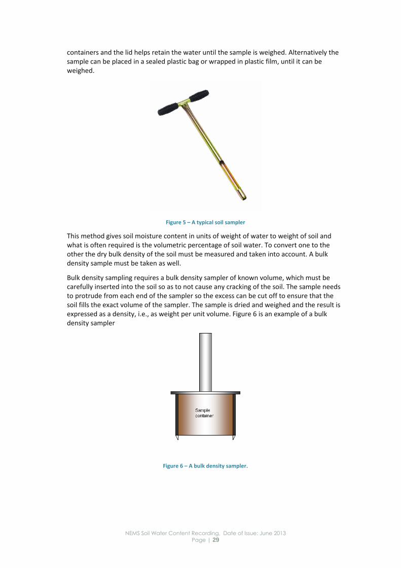
In practice there are soil samplers that will take a precise core of soil (often 25.4 mm in diameter) and these can allow the soil to the sampled in, say 100 mm increments.
If gravimetric sampling is carried out routinely the process can be simplified by placing the samples in lidded tins of a known weight. This removes the need to also weigh the
NEMS Soil Water Content Recording, Date of Issue: June 2013
Page | 29
containers and the lid helps retain the water until the sample is weighed. Alternatively the sample can be placed in a sealed plastic bag or wrapped in plastic film, until it can be weighed.
Figure 5 – A typical soil sampler
This method gives soil moisture content in units of weight of water to weight of soil and what is often required is the volumetric percentage of soil water. To convert one to the other the dry bulk density of the soil must be measured and taken into account. A bulk density sample must be taken as well.
Bulk density sampling requires a bulk density sampler of known volume, which must be carefully inserted into the soil so as to not cause any cracking of the soil. The sample needs to protrude from each end of the sampler so the excess can be cut off to ensure that the soil fills the exact volume of the sampler. The sample is dried and weighed and the result is expressed as a density, i.e., as weight per unit volume. Figure 6 is an example of a bulk density sampler
Figure 6 – A bulk density sampler.
NEMS Soil Water Content Recording, Date of Issue: June 2013
Page | 30
Annex D – Time Domain Reflectometry &
Time Domain Travel
This annex covers the time domain reflectometry & time domain travel measurement of soil water
Advantages
This assessment method:
is an accurate measurement of soil water
enables several measurements can be made to achieve representative measurements of each soil profile, and
is simple to deploy.
Standard calibrations are supplied, but the sensors still need to be calibrated.
Time Domain Reflectometry probes can be connected to a data logger.
Disadvantages
The disadvantages of this method are as follows:
Static discharges to the wave guides could damage the sensitive electronics.
Operation is adversely affected in highly saline soils.
Several sets of rods to depth profile a soil are required if mounted horizontally.
The method only measures close to (~25 mm from each wave guide) the wave guides (probes) so several measurements may be required to get representative soil water contents. The volume of soil sampled depends on the length and number of rods that varies widely between instruments.
The electrical signal can be attenuated in fine textured soils, thereby reducing the reliability of the measurements.
To operate the instrument: 1. Follow the manufacturer’s instructions.
Note: A fast electrical pulse is sent down rods (probes) of known length and separation in the soil. The soil water content affects the speed of the pulse and the speed is electronically measured. The instrument gives a direct reading of the volumetric soil water content.
NEMS Soil Water Content Recording, Date of Issue: June 2013
Page | 31
Annex E – Neutron Probe Assessment
This annex covers the neutron probe assessment of soil water.
Advantages
The neutron probe:
is an accurate measurement of the amount of soil water
is simple to operate
provides an easy depth profile of the amount of soil moisture, and
is unaffected by soil salinity and temperature
Disadvantages
Neutron probes:
are expensive
require an annual calibration check
contain a small radioactive source, requiring:
the operator to hold a license, and
specific requirements for transporting and storing the instrument.
only measure in the immediate vicinity of the probe, so several measurements are required to obtain a representative measurement of soil water content.
require the installation of an access tube into the soil to allow access for the sensor at each measurement site. The tube is usually long enough to measure soil water throughout and beyond the root zone.
Continuous measurement is not practical.
To take a measurement: 1. Follow the manufacturer’s instructions.
Note: Fast particles from a radioactive source are emitted into the soil. Water reduces the speed of the reflected particles. The number of reflected radioactive particles detected over a set period is directly related to the water content of the soil. The instrument gives a direct reading of the water content at selected depths by applying a calibration to the particle count.

NEMS Soil Water Content Recording, Date of Issue: June 2013
Page | 32
Annex F – Capacitance Assessment
This annex covers the capacitance assessment of soil water.
Advantages
Capacitance assessment:
accurately measures the amount of soil moisture, subject to correct installation, and
is simple to operate.
Most instruments can be connected to a data logger.
Standard calibrations are supplied, but the instruments need site calibration.
Disadvantages
The disadvantages of capacitance assessment are as follows:
Static discharge could damage the sensitive electronics in some instruments.
Some instruments are expensive.
Instruments vary in their accuracy and ease of operation.
Measurements are strongly influenced by moisture content and air gaps in the soil close to the electrodes, Good sensor/tube/soil contact is essential for reliable measurements.
Soil salinity and temperature affect measurements and the instruments need calibration to take these effects onto account. The lower the operating frequency, the greater the susceptibility to soil salinity.
Plastic access tubes that may be required are difficult to install in stony soil without significant soil disturbance.
The region of influence around the sensor is typically small 20-30 mm beyond the access tube of sensor.
The sampling volume is small so several measurements sites may be required to obtain representative measurements.
To take a measurement: 1. Follow the manufacturer’s instructions.
Note: The capacitance of the soil varies with its water content. The speed of an electrical pulse travelling down electrodes (probes) placed in the soil depends on the soils capacitance. Capacitance instruments measure the travel speed of the pulse and convert this to soil water content using a calibration equation. The instrument gives a direct reading of volumetric soil water content.