water level indicator by bhushan kumbhalkar
TRANSCRIPT
Presentation OnWATER LEVEL DETECTOR
B.Sc . (3rd Year) in Industrial Science
Submitted By BHUSHAN KUMBHALKAR
CONTENTS:-
INTRODUCTION NEED OF WATERL LEVEL DETECTOR WORKING PRINCIPLE COMPONENTS REQUIRED
a. LED b. TRANSISTOR (BC148) c. RESISTANCE d. CMOS BILATERAL SWITCH
(CD4066) e. PIEZO ELECTRIC BUZZER f. PRINTED CIRCUIT BOARD
ADVANTAGES & APPLICATIONS LIMITATION APPLICATION SCOPE
INTRODUCTION
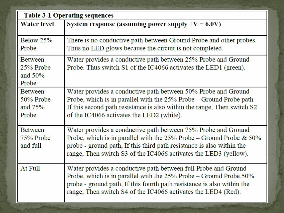
This circuit not only indicates the amount of water present in the overhead tank but also gives an indication when the tank is full. The circuit uses the widely available CD4066, bilateral switch CMOS IC to indicate the water level through LEDs. When the water is empty the wires in the tank are open circuited and the 180K resistors pulls the switch low hence opening the switch and LEDs are OFF. As the water starts filling up, first the wire in the tank connected to S1 and the +supply are shorted by water. This closes the switch S1 and turns the LED1 ON.
As the water continues to fill the tank, the LEDs2, 3 and 4 light up gradually.
NEED OF WATER LEVEL INDICATOR
• Overflow problems.• To prevent wastage of energy.• To prevent wastage of water.• Attention.• Observation.• Automatic switch off.

May 2, 2023
5
Basic DIAGRAM

WORKING PRINCIPLE:-
One electrode probe is with 6V AC is placed at the bottom of tank. Next probes are placed step by step above the bottom probe. When the water/liquid comes in contact with the electrode tip, a conductive path is established between the sense electrode and the tank wall/reference electrode, which in turn makes the transistors conduct to glow LED and indicate the level of water.
The ends of probes are connected to corresponding points in the circuit as shown in circuit diagram. Insulated Aluminum wires with end insulation removed will do for the probe.
Arrange the probes in order on a PVC pipe according to the depth and immerse it in the tank. AC voltage is use to prevent electrolysis at the probes.
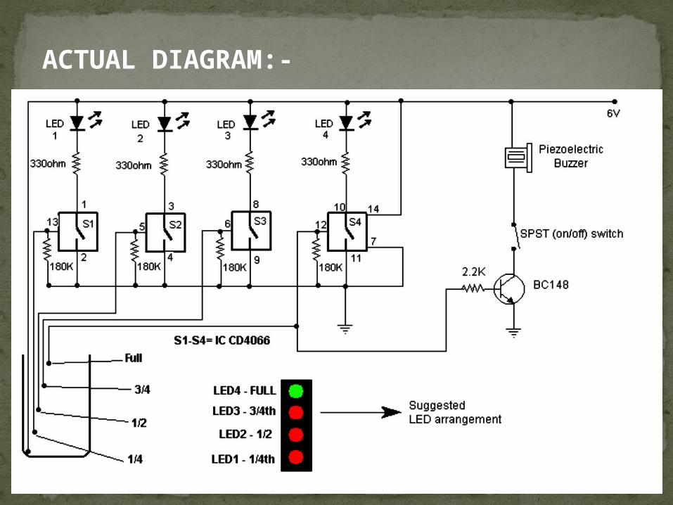
ACTUAL DIAGRAM:-
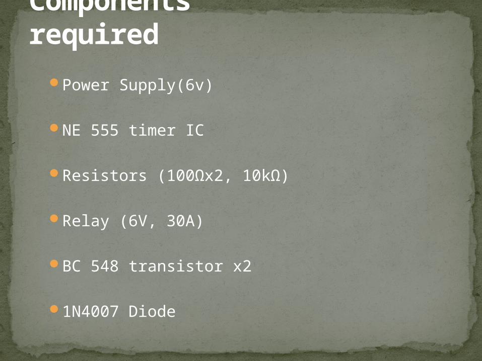
Components required
Power Supply(6v)
NE 555 timer IC
Resistors (100Ωx2, 10kΩ)
Relay (6V, 30A)
BC 548 transistor x2
1N4007 Diode
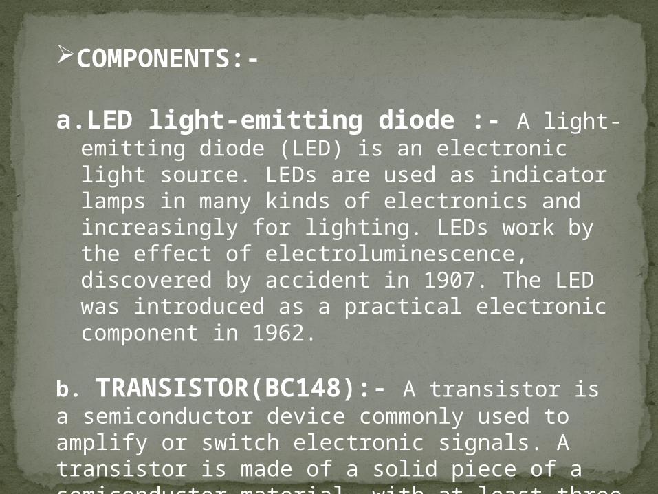
COMPONENTS:-
a.LED light-emitting diode :- A light-emitting diode (LED) is an electronic light source. LEDs are used as indicator lamps in many kinds of electronics and increasingly for lighting. LEDs work by the effect of electroluminescence, discovered by accident in 1907. The LED was introduced as a practical electronic component in 1962.
b. TRANSISTOR(BC148):- A transistor is a semiconductor device commonly used to amplify or switch electronic signals. A transistor is made of a solid piece of a semiconductor material, with at least three terminals for connection to an external circuit
c. RESISTANCE :-The electrical resistance of an object is a measure of its opposition to the passage of a steady electric current. An object of uniform cross section will have a resistance proportional to its length and inversely proportional to its cross- sectional area, and proportional to the resistivity of the material
d. CMOS BILATERAL SWITCH(CD4066) :-The CD4066B is a quad bilateral switch intended for the transmission or Multiplexing of analog or digital signals. It is pin-for-pin compatible with the CD4016B, but exhibits a much lower on-state resistance. In addition, the on-state resistance is relatively constant over the full signal-input range.
application & advantages
May 2, 2023 12
Water level indicator is used in applications like storage tanks, boilers etc. to indicate level of water inside.
Easily indicate when water level is full in tank with beep Sound.
Low cost
Limitations Due to large stray capacitance (from 2-25pF per contact point), high inductance of some connections and a relatively high and not very reproducible contact resistance, solder less breadboards are limited to operate at relatively low frequencies, usually less than 10 MHz, depending on the nature of the circuit. The relative high contact resistance can already be a problem for DC and very low frequency circuits. Solder less breadboards are further limited by their voltage and current ratings.
Solderless breadboards usually cannot accommodate Surface mount technology devices (SMD) or non 0.1" (2.54 mm) grid spaced components, like for example those with 2 mm spacing. Further, they can not accommodate components with multiple rows of connectors, if 10
these connectors don't match the DIL layout (impossible to provide correct electrical connectivity).
SCOPE:- This circuit not only indicates the amount of water present in the overhead tank but also gives an alarm when the tank is full. This worthy device starts ringing as soon as the water tank becomes full. It helps to check overflow and wastage of water by warning the customer when the tank is about to brim. It also provides automatic control of pumps at a remote location. Now no need to go on the roof to look the water level. It shows the water level in your room like 1/4
tank, 1/2 tank, 3/4 tank and full tank. Alarm starts ringing as soon as tank becomes full. Suitable for every tank.
References:- • WWW.SCRIBD.COM• WWW.ELECTRONICSFORYOU.COM• WWW.WIKIPEDIA.COM• WWW.ENGINEERSGARAGE.COM• Fisher WLT Water-Level Indicator Operating Manual. Fisher
Research Laboratory, 200 W. Willmott Road, Los Banos, CA 93635. • Geotech Tuff Tape Water Level Measuring Device Instruction
Manual (11/00). • James, H. (1993). Industrial control electronics. James
Humphries, Delmar Cengage Learning; 4th edition

Thank You

Question & Queries