wastewater lifting stations - · pdf file3 wastewater lifting stations ... according to the...
TRANSCRIPT

3 Wastewaterlifting stations
Lifting stations for wastewater containing raw sewage
for free standing installation andfor installation in a concrete floor Page 66 – 81
for underground installation Page 94 – 101
Lifting stationsfor wastewater without sewage
Complete rangefor free-standing installation andfor installation in a concrete floor Page 82 – 91
for underground installation Page 102 – 105
Submersible pumps Page 106 – 107
for fixed or mobile use,for residential, commercial, publicand industrial applications
Warning and control units Page 108 – 112
Convenient monitoring and controlof lifting stations and pumps
Catalogue 3.0 59
Lif
tin
gsta
tio
ns
3
60 Catalogue 3.0
Wastewater lifting stations –Everything the specialist needs to know
Lif
tin
g s
tati
on
s3
Water flows upwards ?
The reliable function depends on selecting theappropriate lifting station and also on thetechnically correct installation of the liftingstation. KESSEL offers two types of pumps.Non-chokable pumps and macerator pumps.Each of these pumps has special properties.
Non-chokable pumps have a largefree space inside the pump housing.As a consequence, solid and long
fibrous, high consistency substances, such assanitary towels, textiles etc., can pass throughthe pump housing easily. It is often necessaryto expend more energy to achieve an efficientpump output.
Macerator pumps are especiallysuitable for long fibres and where solidbodies can be comminuted, even larger
sizes. This allows the wastewater to betransported reliably through small pressure pipeseven over long distances (pressure drainage).
Particle size: The particle size of a pumpspecifies how many millimetres of freepassage through the pump are available.According to the construction and testingregulations (EN 12050-2) for wastewater liftingstations for wastewater without sewage (greywater), the minimum solids size (particle size) inthe overall system is 10 mm, for wastewater withsewage (black water) it is 40 mm (EN 12050-1).
Pumping volume: Another important point is thepumping volume of a lifting station. EN 12056-4requires the pumping volume of the system tobe larger than the total volume of the pressurepipe. This means that the wastewater in thepressure line is replaced during every pumpingprocess. And if the backwater preventer isleaking this does not lead to the pumpswitching on and off all the time.
Explosion protection: Misuse oraccidents can lead to substanceswhich can form an explosive mixture
getting into a lifting station or pumping station.If a potentially explosive atmosphere is to beexpected, systems with explosion protection(ATEX) must be planned.
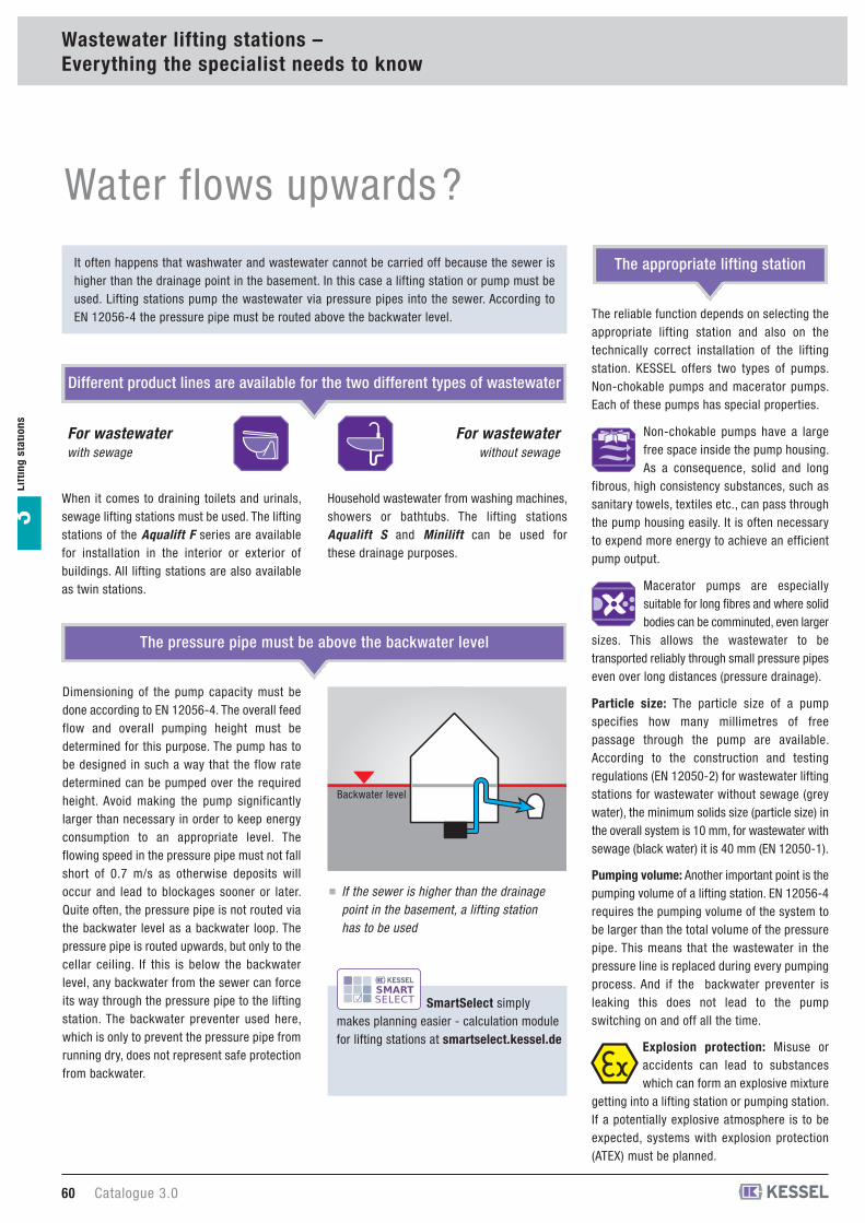
The appropriate lifting stationIt often happens that washwater and wastewater cannot be carried off because the sewer ishigher than the drainage point in the basement. In this case a lifting station or pump must beused. Lifting stations pump the wastewater via pressure pipes into the sewer. According toEN 12056-4 the pressure pipe must be routed above the backwater level.
Different product lines are available for the two different types of wastewater
The pressure pipe must be above the backwater level
When it comes to draining toilets and urinals,sewage lifting stations must be used. The liftingstations of the Aqualift F series are availablefor installation in the interior or exterior ofbuildings. All lifting stations are also availableas twin stations.
For wastewater without sewage
For wastewater with sewage
Household wastewater from washing machines,showers or bathtubs. The lifting stationsAqualift S and Minilift can be used forthese drainage purposes.
Backwater level
If the sewer is higher than the drainage
point in the basement, a lifting station
has to be used
Dimensioning of the pump capacity must bedone according to EN 12056-4. The overall feedflow and overall pumping height must bedetermined for this purpose. The pump has tobe designed in such a way that the flow ratedetermined can be pumped over the requiredheight. Avoid making the pump significantlylarger than necessary in order to keep energyconsumption to an appropriate level. Theflowing speed in the pressure pipe must not fallshort of 0.7 m/s as otherwise deposits willoccur and lead to blockages sooner or later.Quite often, the pressure pipe is not routed viathe backwater level as a backwater loop. Thepressure pipe is routed upwards, but only to thecellar ceiling. If this is below the backwaterlevel, any backwater from the sewer can forceits way through the pressure pipe to the liftingstation. The backwater preventer used here,which is only to prevent the pressure pipe fromrunning dry, does not represent safe protectionfrom backwater.
SmartSelect simplymakes planning easier - calculation modulefor lifting stations at smartselect.kessel.de
Catalogue 3.0 61
Lif
tin
gsta
tio
ns
3
Wastewater lifting stations –Everything the specialist needs to know
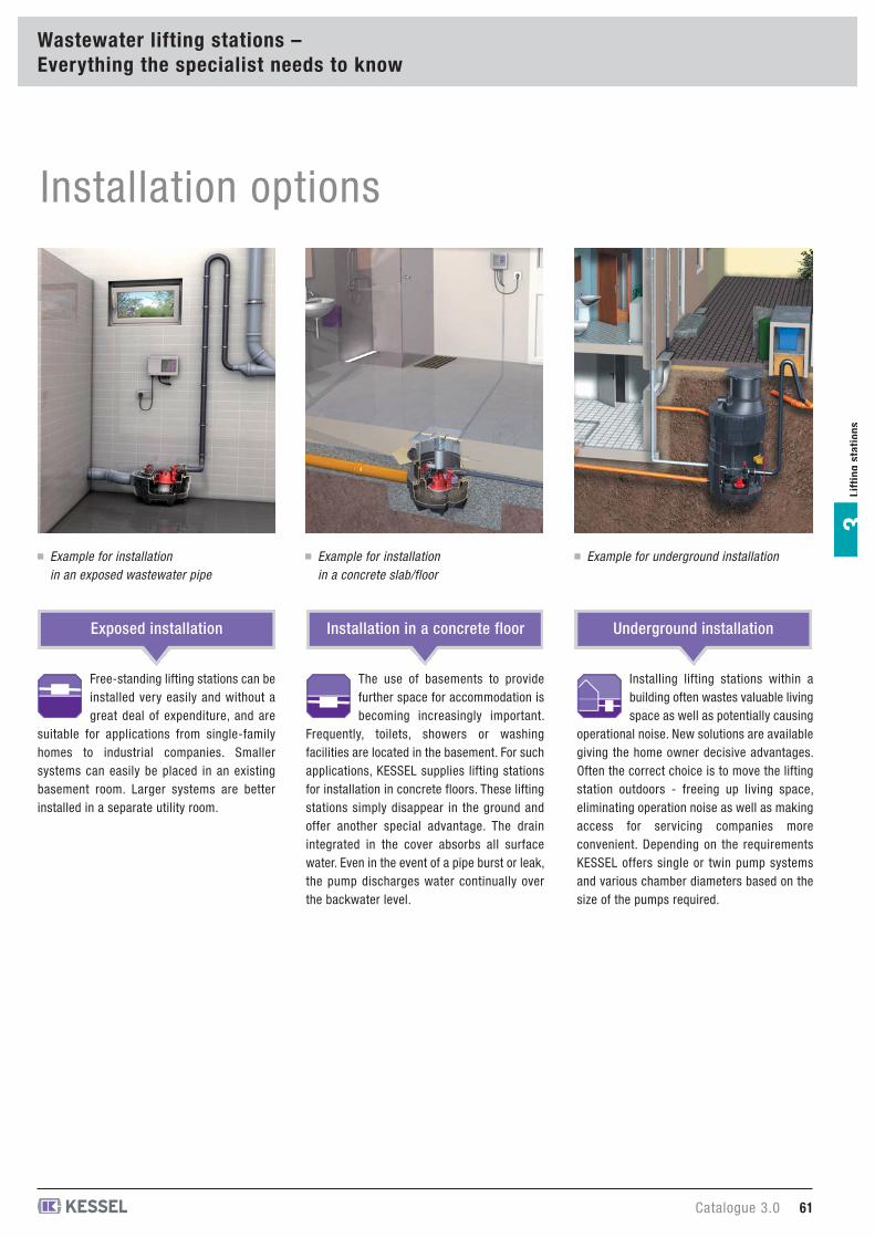
Installation options
Installing lifting stations within abuilding often wastes valuable livingspace as well as potentially causing
operational noise. New solutions are availablegiving the home owner decisive advantages.Often the correct choice is to move the liftingstation outdoors - freeing up living space,eliminating operation noise as well as makingaccess for servicing companies moreconvenient. Depending on the requirementsKESSEL offers single or twin pump systemsand various chamber diameters based on thesize of the pumps required.
The use of basements to providefurther space for accommodation isbecoming increasingly important.
Frequently, toilets, showers or washingfacilities are located in the basement. For suchapplications, KESSEL supplies lifting stationsfor installation in concrete floors. These liftingstations simply disappear in the ground andoffer another special advantage. The drainintegrated in the cover absorbs all surfacewater. Even in the event of a pipe burst or leak,the pump discharges water continually overthe backwater level.
Free-standing lifting stations can beinstalled very easily and without agreat deal of expenditure, and are
suitable for applications from single-familyhomes to industrial companies. Smallersystems can easily be placed in an existingbasement room. Larger systems are betterinstalled in a separate utility room.
Exposed installation Installation in a concrete floor Underground installation
Example for installation
in an exposed wastewater pipe
Example for installation
in a concrete slab/floor
Example for underground installation
INFORMATION
62 Catalogue 3.0
Wastewater lifting stations –Everything the specialist needs to know
Lif
tin
g s
tati
on
s3
General information and standards
Level sensors / probes and alarm probes
If the water level rises within the collectingtank, the switching device is triggered via thechange in level of the float, and the liftingstation pump is activated.Float switches are a simple and proven type oflevel measurement. They have someweaknesses when heavily soiled wastewater isto be pumped, since material becomesdeposited on the float and can interfere withlevel measurement.
Level sensorWith this method of hydrostaticpressure measurement, the water
pressure is measured using a semiconductorand the downstream electronics generate ananalogue signal from this. The pumps areactivated from a specified level onward.A level probe can be used to measure differentlevels. This makes it possible to measure boththe alarm level and pumping level and save ona second probe. However, such level probesusually cost more than other level sensors.
Optical probeIn addition to the level sensorsdescribed above, an optical probe
can be used as an alarm probe. If the sensorsurface becomes wet, the refraction angle of aninfrared signal changes, signalling that thealarm level has been reached.The optical probe is ideal as an alarm probesince it works reliably even if it has not been inuse for a long time. An alarm can be triggeredby mistake, however, when the wastewater iswarm (dripping condensate) or heavily foaming.
Level sensors and probes measures the levelof the pumping medium in the collecting tank ofa lifting station and trigger the pumping processof one or several pumps from a specified fillinglevel onward. If the level in the collecting tankcontinues to rise, an acoustic warning signalcan be give via an alarm probe (which alsomeasures the level of the pumping medium).
Pressure sensorThe closed air volume within asubmersible pipe / bell is compressed
by a rising water level in the collecting tank ofa lifting station. The resulting difference in airpressure is measured by a pressure sensor inthe control unit and used to regulate the startingand stopping of the lifting station pumpingprocess. Pneumatic level measurement is astraightforward and low-cost method of levelmeasurement, but does have disadvantageswhen the system is used irregularly, whenwastewater is extremely greasy, wherepressure hoses are very long or condensate inthe pressure hose impedes measurement.
Conductance probeA conductance probe uses AC voltageand measures whether there is any
conductive fluid between two measuring points.If there is, current flows and the control unittriggers the pumping process. Thus aconductance probe is a simple and low-costmethod of level measurement. It only workswith conductive fluids, however, and cannot beused for the pumping of rainwater or condensate.
Float switchFloat switches are switching deviceswhich are actuated by a float which
swims on the surface of the pumping medium.
Which standards must be taken into account ?
EN 12056 Gravity drainage systems inside buildings
EN 752 Drainage systems outside buildings
EN 13564 Backwater valves for buildings
EN 1253-5 Drains for buildings withvolatile liquid traps
EN 12050 Lifting stations for buildings
Do you require more detailed information ?Our Service Centre will be happy to help.
You can find your personal KESSEL contacton page 3 of this catalog !
Complete System SolutionIn addition to individual lifting andpumping station, KESSEL also offersother systems the drainage of buildings.Do you hvae a natural gradient to thesewer ?
World innovation Ecolift - the alternativeto a standard lifting station with gravitysloped drainage see chapter 2 “hybridlifting systems”.Backwater valves for interior andunderground installation see chapter 1“backwater valves”.
Individual SolutionsThanks to the knowledge and possibilitiesin the field of polyethylene technologyKESSEL is not only able to manufactureseries products, but also special solutionsin accordance with project-specificrequirements. For additional informationplease take a look at the IndividualSolutions section of this catalogueon page 283.
ReferencesOver the past decades, KESSEL productshave proven themselves countless times indestinations all over the world. Scan thefollowing QR code to directly view our list ofreferences.
www.kessel.com/references
Catalogue 3.0 63
Lif
tin
gsta
tio
ns
3
Wastewater lifting stations –Everything the specialist needs to know
Selection criteria - lifting stations
Aqualift F
Products see page
Aqualift FØ 1000
P1.3 - 1.9 kW
28 m
63 / 90 mm
Impeller
AP 501Ø 800/1000
P1.1- 1.25 kW
12 m
63 / 90 mm
Impeller
P1.4 - 3 kW
16 m
110 mm
Impeller
Aqualift FØ 600
P1 kW
9 m
40 mm
Macerator
Aqualift FXXL
P
2.6 - 4.8 kW
20 m
110 mm
Impeller
Aqualift FXL
PP
1.4 - 5 kW
27 m
110 mm
Impeller
Aqualift FCompact
P
1 kW
9 m
40 mm
Macerator
Ecolift
P
1 kW
9 m
40 mm
Macerator
Interior installation
Input power
Exterior installation
Pressure pipe diameter
Pump
Max. pumping height
FOR WASTEWATER CONTAINING RAW SEWAGE
Aqualift S
Products see page
Aqualift SØ 1000
P500 or 1000 W
9 m
40 mm
Impeller
500 W
7 m
40 mm
Impeller
Aqualift SØ 600
P500 or 1000 W
9 m
40 mm
Impeller
P
Minilift
P
300 W
5 m
40 mm
Impeller
Interior installation
Input power
Exterior installation
Pressure pipe diameter
Pump
Max. pumping height
FOR WASTEWATER WITHOUT SEWAGE
949872 967874 - 766654
10484 - 86 10288
64 Catalogue 3.0
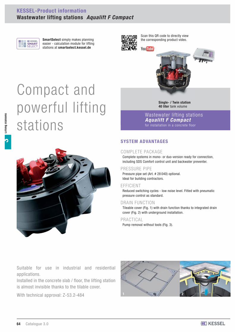
KESSEL-Product informationWastewater lifting stations Aqualift F Compact
Lif
tin
g s
tati
on
s3
Suitable for use in industrial and residentialapplications. Installed in the concrete slab / floor, the lifting stationis almost invisible thanks to the tilable cover.
With technical approval: Z-53.2-484
COMPLETE PACKAGEComplete systems in mono- or duo-version ready for connection,including SDS Comfort control unit and backwater preventer.
PRESSURE PIPEPressure pipe set (Art. # 28 040) optional.Ideal for building contractors.
EFFICIENTReduced switching cycles - low noise level. Fitted with pneumaticpressure control as standard.
DRAIN FUNCTIONTileable cover (Fig. 1) with drain function thanks to integrated draincover (Fig. 2) with underground installation.
PRACTICALPump removal without tools (Fig. 3).
SYSTEM ADVANTAGES
Wastewater l i f t ing stat ionsAqualift F Compactfor instal lat ion in a concrete f loor
1 2
Single- / Twin station40 liter tank volume
SmartSelect simply makes planning easier - calculation module for lifting stations at smartselect.kessel.de
Scan this QR code to directly view the corresponding product video.
Compact andpowerful liftingstations

Catalogue 3.0 65
Lif
tin
gsta
tio
ns
3
Wastewater l i f t ing stat ionsAqualift F Compactfor free standing instal lat ion
3 54
Single station40 liter tank volume
Twin station40 liter tank volume
MENU NAVIGATIONUser-friendly menu navigation in six languages with multi-lingualdisplay (Fig. 4).
SELF-DIAGNOSIS SYSTEM SDSPlug-and-play control units with self-diagnosis system SDSand monthly self-test. Comfort version with display for operatingstate and maintenance instructions.
FUNCTION PARAMETERSSimple and customised adjustment of function parameters -can also be used for pumps from other manufacturers.
LOG BOOKElectronic log book can be read out using USB flash drive.
READY FOR CONNECTION230 Volt control unit ready for connection by coded connectors(Fig. 5) for pumps and pressure sensor - no need for a qualifiedelectrician for connection.
POTENTIAL-FREE SWITCH CONTACTPotential-free contact as an optional connection possibilityfor building management systems using 230 Volt control units.
REMOTE SIGNAL GENERATORConnection for remote signal generator.
GSM-INTERFACERelaying of collective error messages via potential-free contactsand GSM-interface optional.
USB-BOARD SOCKETIncluding USB board socket on 230 Volt control units. For readingout the electronic log and downloading and uploading operation-related parameters. USB housing socket optional.
TeleControl TELEMETRIC SYSTEMFor connection to KESSEL Comfort control units 230 Volt and 400 Volt.Relaying of full text messages to up to three mobile phones. WithoutSIM card.
COMFORT CONTROL UNIT
Lifting station Aqualift F Compact Mono / Duo for free-standing installationWith lateral inlet Ø 110
Aqualift F Compact Monowith one removable pump, pressure sensorcontrolled, with integrated backwater flapAqualift F Compact Duowith two removable pumps, pressure sensorcontrolled, with integrated backwater flap
With SDS control unit (self-diagnosis system)for fully automatic pump control, splashwater-protected (IP 54), wall mounted.Pressure connection: 11/2 inch outer thread orpressure pipe Ø 40 mm for PVC glued connection or pressure pipe set (accessories Art. # 28 040)Pumping height: max. 9.5 m, Qmax = 10.9 m3/hVoltage: 230 V ~ 50 Hz.Power cable: 5 m.A ventilation pipe must be provided for on site.
Lifting stationsfor wastewater with or without sewage
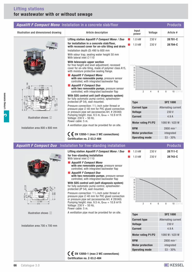
Aqualift F Compact Mono Installation in a concrete slab/floor Products
Illustration and dimensioned drawing Article description
66 Catalogue 3.0
28 701-C230 V1.0 kWLifting station Aqualift F Compact Mono / Duo for installation in a concrete slab/floor, with recessed cover for on-site tiling and drainInstallation depth (D) 490 to 600 mmWith odour trap, sealing water height 50 mmWith lateral inlet Ø 110
With telescopic upper sectionfor free height and level adjustment, recessedcover for on-site tiling, made of polymer class A15,with moisture protective sealing flange.
Aqualift F Compact Monowith one removable pump, pressure sensorcontrolled, with integrated backwater flapAqualift F Compact Duowith two removable pumps, pressure sensorcontrolled, with integrated backwater flap
With SDS control unit (self-diagnosis system)for fully automatic pump control, splashwater-protected (IP 54), wall mounted.Pressure connection: 11/2 inch outer thread orpressure pipe Ø 40 mm for PVC glued connection or pressure pipe set (accessories Art. # 28 040)Pumping height: max. 9.5 m, Qmax = 10.9 m3/hVoltage: 230 V ~ 50 Hz.Power cable: 5 m.A ventilation pipe must be provided for on site.
123456789
2 4 6 8 10 Q [m3/h]
H [m]
123456789
2 4 6 8 10 Q [m3/h]
H [m]
Certification no. Z-53.2-484
Lif
tin
g s
tati
on
s3
VoltageInput power Article #
EN 12050-1 (max 2 WC connections)
Certification no. Z-53.2-484
EN 12050-1 (max 2 WC connections)
Aqualift F Compact Duo Installation for free-standing installation Products
Installation area 700 x 700 mm
1
2
1
2
1
28 704-C230 V1.0 kW2
28 711-C230 V1.0 kW1
28 743-C230 V1.0 kW2
351
295
Ø 590
Ø 4
0
80207
Ø 1
1042
0D 12
2
40070 -
180
Illustration shows 2
Illustration shows 2
Installation area 800 x 800 mm
395
351
670Ø 580
Ø 4
0
80207
Ø 1
10
Alternating current
230 V
4.9 A
1080 W / 620 W
2800 min-1
integrated
S3 - 30%
Current type
Voltage
Current
Motor rating P1/P2
RPM
Motor protection
Operating mode
SPZ 1000Type
Alternating current
230 V
4.9 A
1080 W / 620 W
2800 min-1
integrated
S3 - 30%
Current type
Voltage
Current
Motor rating P1/P2
RPM
Motor protection
Operating mode
SPZ 1000Type

Catalogue 3.0 67
Lif
tin
gsta
tio
ns
3
Lifting stationsfor wastewater with or without sewage
Installation example Aqualift F Compact Professional advantages
�
�
�
Installation example Aqualift F Compact Professional advantages
�
�
Plug & play Comfort control unitwith self-diagnosis system SDSfor maximum safety.
Integrated drain function to drain surfacewater. Continual drainage even in the eventof incoming flood water or a pipe burst.
Variable upper sectionrotatable, tiltable and height adjustable
Installation in waterproof concrete. Gasketset (Art. # 83 023) to prevent groundwaterinfiltration.
Elegant optical appearance even forbasement rooms which are used as livingaccommodation: The modern alternative toa pump chamber.
Chamber ready to be installed, recessedinstallation in the concrete slab/floor possiblewith extension section.
TeleControl telemetric systemRelaying of full text messages to up to threemobile phones.
Plug & play Comfort control unitwith self-diagnosis system SDSfor maximum safety.
Ideal for later installation, including forrenovation work, and for installation in anexisting pump sump.
Space-savingCompact and attractive-looking liftingstation - base area only 70 x 70 cm.
Ready for connectionAssembled ready for connection withhorizontal or vertical pressure outlet.
Further inletsPossible connection of further inlets directlyon site.
The wastewater lifting station Aqualift F Compact � takes over the complete basement drainageand pumps wastewater reliably and completely automatically through the pressure pipe set �via the backwater level to the higher-level sewage system. The system is delivered as a ready-to-install chamber which can be installed in waterproof concrete with the aid of the extensionsection � and sealing gasket set �. Control is by means of the Comfort control unit � withself-diagnosis system SDS. Installation in the concrete slab/floor makes the Aqualift F Compact
the modern alternative to a “pump sump”.
The wastewater lifting station Aqualift F Compact � takes over the complete basement drainageand pumps wastewater with and without sewage reliably and completely automatically via thebackwater level to the higher-level sewage system. Control is by means of the Comfort controlunit � with self-diagnosis system SDS. Its compact design makes the system ideal for renovationwork.
��
Scan this QR code to directly view the corresponding product video.

83 075-Extension section with centre flangewith elastomer sealing sheet made of NK/SBR Ø 800 mm, incl. screwsfor article numbers: 28 701-C, 28 704-C
83 050-
Cover plate, surface water tightClass A 15made of polymer, incl. gasket Art. # 173-145
blackVentilation always required when in use !
recessed for on-site tiling, grey,for tile thicknesses of 18 mmVentilation always required when in use !
for article numbers: 28 701-C, 28 704-C
83 052-
83 061-Upper sectionmade of polymer, max. extension 180 mm, height adjustablefor article numbers: 28 701-C, 28 704-C
414
450 400 22
222
�
��
83 045-
83 046-
Cover plate, surface water tightClass A 15With drain Ø 75, includes Multistop odour, foam, rodent and insect stopincl. gasket
recessed for on-site tiling, grey,for tile thicknesses of 18 mm
with integrated grating, black
for article numbers: 28 701-C, 28 704-C
For models made on or after Jan 2011
1
2
1
2
2
1
� 384 42
107
� 384 42
107
43 700-Hair filtermade of polymerfor article numbers: 83 045 and 83 046
14
�109
27 602Ø 75/110Transition section Ø 110 / 75Ø 110 socket / Ø 75 spigotcan be used as an upper section, incl. gasketfor article numbers: 28 701-C, 28 704-C, 28 711-C, 28 743-C
131
� 7
5
� 1
10
Lifting stations
Aqualift F Compact Accessories
Illustration and dimensioned drawing Article description
Lif
tin
g s
tati
on
s3
83 023-Gasket setfor installation in waterproof concrete
Consisting of:Counter flange made of polymer, incl. screws, elastomer waterproof membranein NK/SBR Ø 800 mm
for article numbers: 28 701-C, 28 704-C
83 071-Extension section with flangemade of polymer, max. extension 180 mm, incl. gasketFor gasket set Art. # 83 023for article numbers: 28 701-C, 28 704-C
�414
40
230
180
�59010
WU Einbau geprüft von MFPA Leipzig UB 5.1/11-452-1
68 Catalogue 3.0
Outer diameterØ (mm) Article #
When multiple extension sections are used make sure that access to valve is still possible !

28 794Antenna booster extension cablecable length 2.5 m
28 792TeleControl telemetric systemfor connection to KESSEL Comfort control units230 Volt and 400 Volt. Relaying of full text messages to up to threemobile phones. Without SIM card.
28 793
-
-
-TeleControl antenna boosterfor TeleControl telemetric systemincl. 2.5 m cable to improve reception.With magnetic base.
28 016-Retrofit kit alarm float switch for lifting stations Aqualift F Compact Can be combined with 230 V Comfort control units.Comprises a float switch, float switch bracket and5 m connection cable.
28 048-Compressor set for bubble formationfor use in combination with lifting stations andpumping stations with pressure control:
prevents soiling, compensates leaks, avoidscondensate forming in the pressure hose,makes operation of systems possible withpressure hose lengths > 10 m, includingconnection T-piece, including 10 m pressurehose.
20 162-Audible alarm20 m cable length
suitable for all control units
80 072-Potential-free contactsuitable for all control units 230 V: Wastewater station Aqualift F, Wastewater station Aqualift F Compact,Lifting station Aqualift F Mono 230 V
28 040Ø 40Pressure pipe setIncl. 5 m pressure pipe hose Ø 40
for article numbers: 28 701-C, 28 704-C, 28 711-C, 28 743-C
Catalogue 3.0 69
Aqualift F Compact Accessories
Illustration and dimensioned drawing Article description
Lifting stations
Lif
tin
gsta
tio
ns
3
83 070-Extension section made of polymer, max. extension 180 mm, incl. gasketfor article numbers: 28 701-C, 28 704-C
480
41415
020
0
�
�
Outer diameterØ (mm) Article #
When multiple extension sections are used make sure that access to valve is still possible !
70 Catalogue 3.0
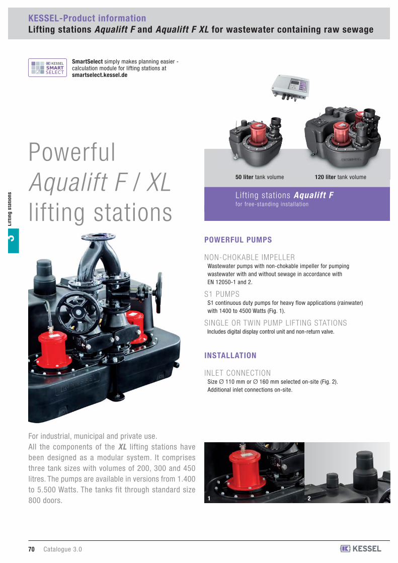
KESSEL-Product informationLifting stations Aqualift F and Aqualift F XL for wastewater containing raw sewage
Lif
tin
g s
tati
on
s3
Powerful Aqualift F / XLlifting stations
For industrial, municipal and private use. All the components of the XL lifting stations havebeen designed as a modular system. It comprisesthree tank sizes with volumes of 200, 300 and 450litres. The pumps are available in versions from 1.400to 5.500 Watts. The tanks fit through standard size800 doors.
NON-CHOKABLE IMPELLERWastewater pumps with non-chokable impeller for pumpingwastewater with and without sewage in accordance withEN 12050-1 and 2.
S1 PUMPSS1 continuous duty pumps for heavy flow applications (rainwater)with 1400 to 4500 Watts (Fig. 1).
SINGLE OR TWIN PUMP LIFTING STATIONSIncludes digital display control unit and non-return valve.
POWERFUL PUMPS
INSTALLATION
INLET CONNECTIONSize Ø 110 mm or Ø 160 mm selected on-site (Fig. 2).Additional inlet connections on-site.
50 liter tank volume 120 liter tank volume
1 2
SmartSelect simply makes planning easier -calculation module for lifting stations at smartselect.kessel.de
Lift ing stat ions Aqualift Ffor free-standing instal lat ion
Catalogue 3.0 71
Lif
tin
gsta
tio
ns
3
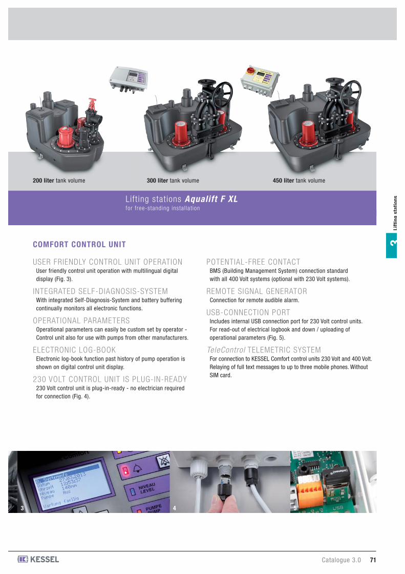
USER FRIENDLY CONTROL UNIT OPERATIONUser friendly control unit operation with multilingual digitaldisplay (Fig. 3).
INTEGRATED SELF-DIAGNOSIS-SYSTEMWith integrated Self-Diagnosis-System and battery bufferingcontinually monitors all electronic functions.
OPERATIONAL PARAMETERSOperational parameters can easily be custom set by operator -Control unit also for use with pumps from other manufacturers.
ELECTRONIC LOG-BOOKElectronic log-book function past history of pump operation isshown on digital control unit display.
230 VOLT CONTROL UNIT IS PLUG-IN-READY230 Volt control unit is plug-in-ready - no electrician requiredfor connection (Fig. 4).
POTENTIAL-FREE CONTACTBMS (Building Management System) connection standardwith all 400 Volt systems (optional with 230 Volt systems).
REMOTE SIGNAL GENERATORConnection for remote audible alarm.
USB-CONNECTION PORT Includes internal USB connection port for 230 Volt control units.For read-out of electrical logbook and down / uploading ofoperational parameters (Fig. 5).
TeleControl TELEMETRIC SYSTEMFor connection to KESSEL Comfort control units 230 Volt and 400 Volt.Relaying of full text messages to up to three mobile phones. WithoutSIM card.
COMFORT CONTROL UNIT
Lift ing stat ions Aqualift F XLfor free-standing instal lat ion
200 liter tank volume 300 liter tank volume 450 liter tank volume
43 5
EN 12050 - 1guaranteed with
tested quality
Type-testedand monitored
LGA
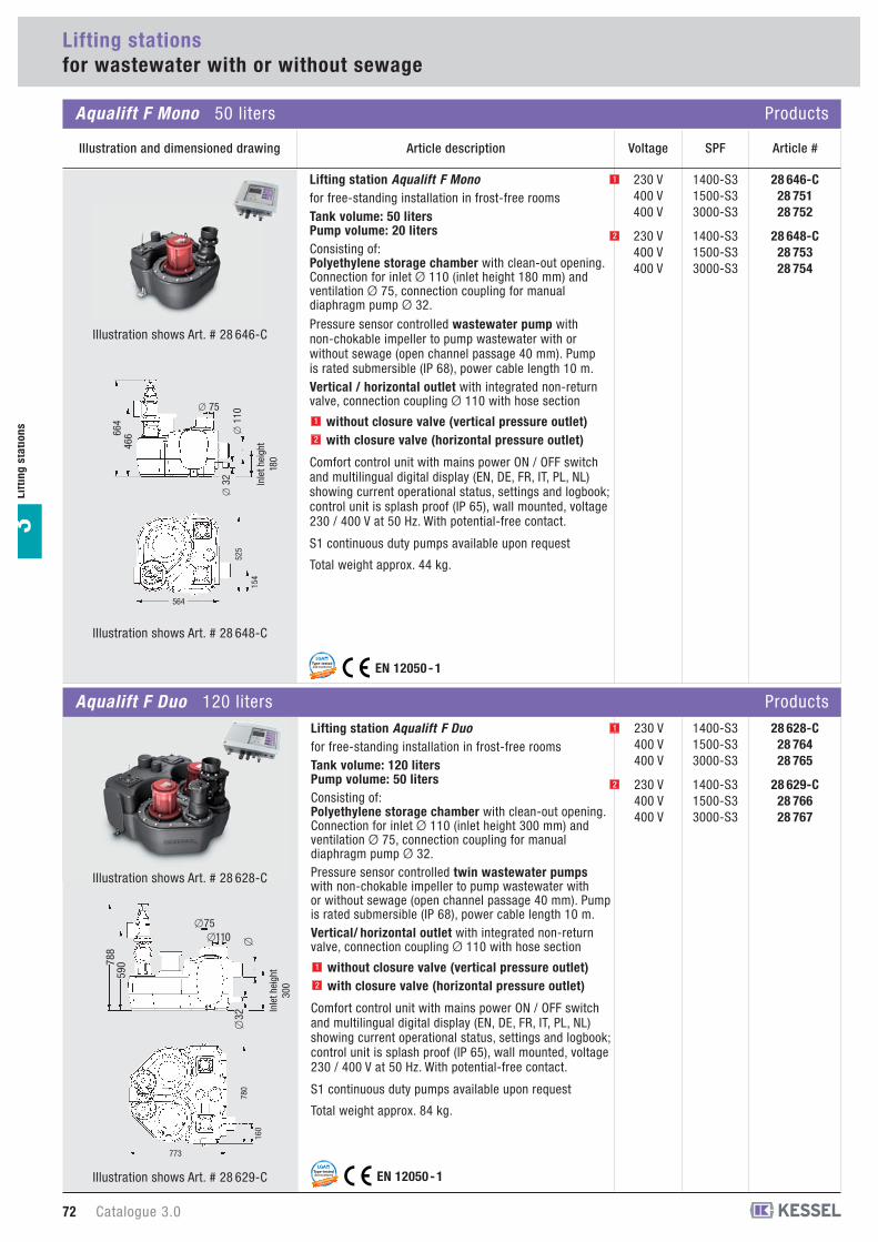
Lifting station Aqualift F Monofor free-standing installation in frost-free roomsTank volume: 50 litersPump volume: 20 litersConsisting of:Polyethylene storage chamber with clean-out opening.Connection for inlet Ø 110 (inlet height 180 mm) andventilation Ø 75, connection coupling for manualdiaphragm pump Ø 32.
Pressure sensor controlled wastewater pump withnon-chokable impeller to pump wastewater with orwithout sewage (open channel passage 40 mm). Pumpis rated submersible (IP 68), power cable length 10 m. Vertical / horizontal outlet with integrated non-returnvalve, connection coupling Ø 110 with hose section
without closure valve (vertical pressure outlet)with closure valve (horizontal pressure outlet)
Comfort control unit with mains power ON / OFF switchand multilingual digital display (EN, DE, FR, IT, PL, NL)showing current operational status, settings and logbook;control unit is splash proof (IP 65), wall mounted, voltage230 / 400 V at 50 Hz. With potential-free contact.
S1 continuous duty pumps available upon request
Total weight approx. 44 kg.
1
28 646-C28 75128 752
230 V400 V400 V
1400-S31500-S33000-S3
28 648-C28 75328 754
230 V400 V400 V
1400-S31500-S33000-S3
EN 12050 - 1guaranteed with
tested quality
Type-testedand monitored
LGA
Lifting stationsfor wastewater with or without sewage
Aqualift F Mono 50 liters Products
Lif
tin
g s
tati
on
s3
Illustration and dimensioned drawing Article description
525
564
154
664
466
� 3
2�
110
� 75
Inle
t hei
ght
180
SPFVoltage Article #
1
2
2
Aqualift F Duo 120 liters ProductsLifting station Aqualift F Duofor free-standing installation in frost-free roomsTank volume: 120 litersPump volume: 50 litersConsisting of:Polyethylene storage chamber with clean-out opening.Connection for inlet Ø 110 (inlet height 300 mm) andventilation Ø 75, connection coupling for manualdiaphragm pump Ø 32.Pressure sensor controlled twin wastewater pumpswith non-chokable impeller to pump wastewater withor without sewage (open channel passage 40 mm). Pumpis rated submersible (IP 68), power cable length 10 m. Vertical/ horizontal outlet with integrated non-returnvalve, connection coupling Ø 110 with hose section
without closure valve (vertical pressure outlet)with closure valve (horizontal pressure outlet)
Comfort control unit with mains power ON / OFF switchand multilingual digital display (EN, DE, FR, IT, PL, NL)showing current operational status, settings and logbook;control unit is splash proof (IP 65), wall mounted, voltage230 / 400 V at 50 Hz. With potential-free contact.
S1 continuous duty pumps available upon request
Total weight approx. 84 kg.
1
2
1 28 628-C28 76428 765
230 V400 V400 V
1400-S31500-S33000-S3
28 629-C28 76628 767
230 V400 V400 V
1400-S31500-S33000-S3
2
788
590
�32
�110�75
�
773
780
160
72 Catalogue 3.0
Inle
t hei
ght
300
Illustration shows Art. # 28 646-C
Illustration shows Art. # 28 648-C
Illustration shows Art. # 28 628-C
Illustration shows Art. # 28 629-C
Catalogue 3.0 73
Lif
tin
gsta
tio
ns
3
1234567
10 20 30
SPF 1500
Q [m3/h]
H [m]
SPF 1400
Qmin for Ø 90 mm*
Qmin for Ø 110 mm*
2468
10121416
10 20 30 40
SPF 3000
H [m]
Q [m3/h]
Qmin for Ø 90 mm*
Qmin for Ø 110 mm*
Installation example Aqualift F Professional advantages
�
�
Lifting stationsfor wastewater with or without sewage
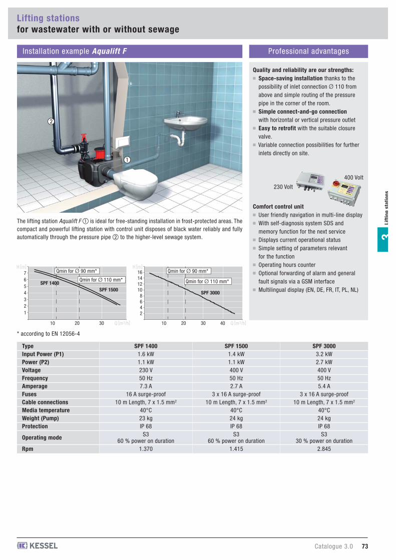
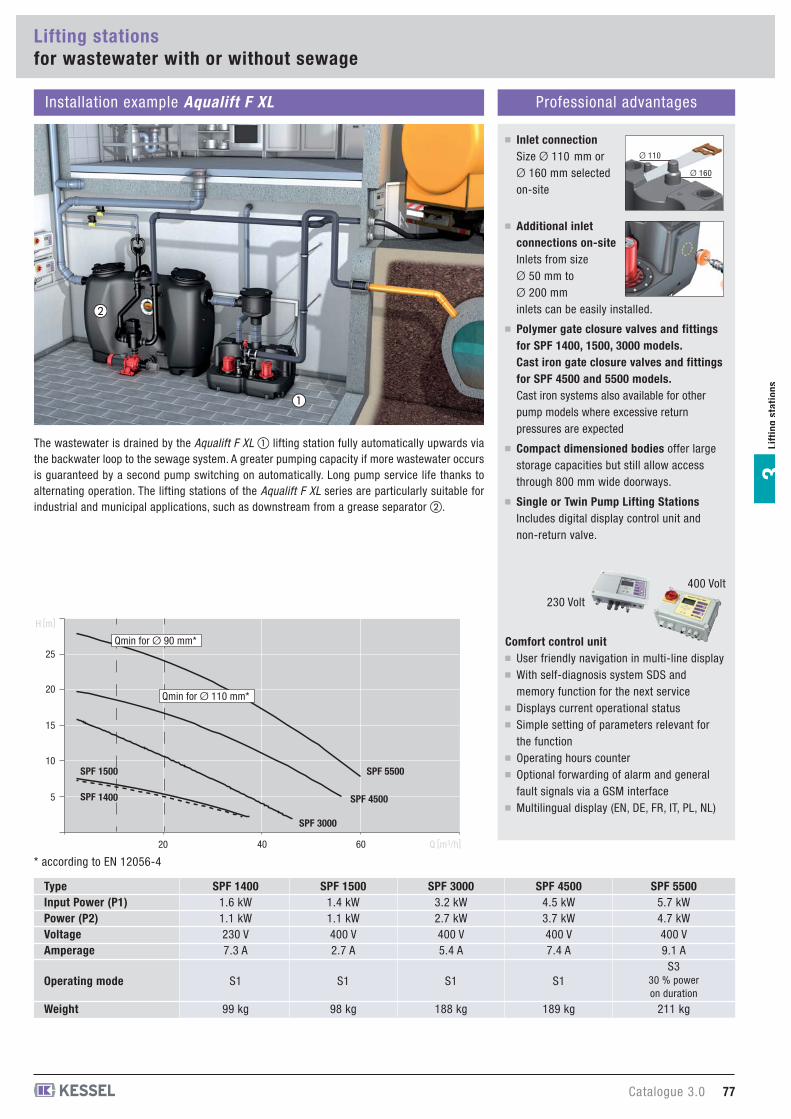
Quality and reliability are our strengths:Space-saving installation thanks to thepossibility of inlet connection Ø 110 fromabove and simple routing of the pressurepipe in the corner of the room.Simple connect-and-go connectionwith horizontal or vertical pressure outletEasy to retrofit with the suitable closurevalve. Variable connection possibilities for furtherinlets directly on site.
Comfort control unitUser friendly navigation in multi-line displayWith self-diagnosis system SDS andmemory function for the next serviceDisplays current operational statusSimple setting of parameters relevantfor the functionOperating hours counterOptional forwarding of alarm and generalfault signals via a GSM interfaceMultilingual display (EN, DE, FR, IT, PL, NL)
SPF 30003.2 kW2.7 kW400 V 50 Hz5.4 A
3 x 16 A surge-proof10 m Length, 7 x 1.5 mm2
40°C24 kgIP 68
S330 % power on duration
2.845
SPF 15001.4 kW1.1 kW400 V50 Hz2.7 A
3 x 16 A surge-proof10 m Length, 7 x 1.5 mm2
40°C24 kgIP 68
S360 % power on duration
1.415
SPF 14001.6 kW1.1 kW230 V 50 Hz7.3 A
16 A surge-proof10 m Length, 7 x 1.5 mm2
40°C23 kgIP 68
S360 % power on duration
1.370
TypeInput Power (P1)Power (P2)VoltageFrequencyAmperageFusesCable connectionsMedia temperatureWeight (Pump)Protection
Operating mode
Rpm
* according to EN 12056-4
The lifting station Aqualift F � is ideal for free-standing installation in frost-protected areas. Thecompact and powerful lifting station with control unit disposes of black water reliably and fullyautomatically through the pressure pipe � to the higher-level sewage system.
400 Volt
230 Volt
Lifting stationsfor wastewater with or without sewage
Aqualift F XL 200 liters Products
Lif
tin
g s
tati
on
s3
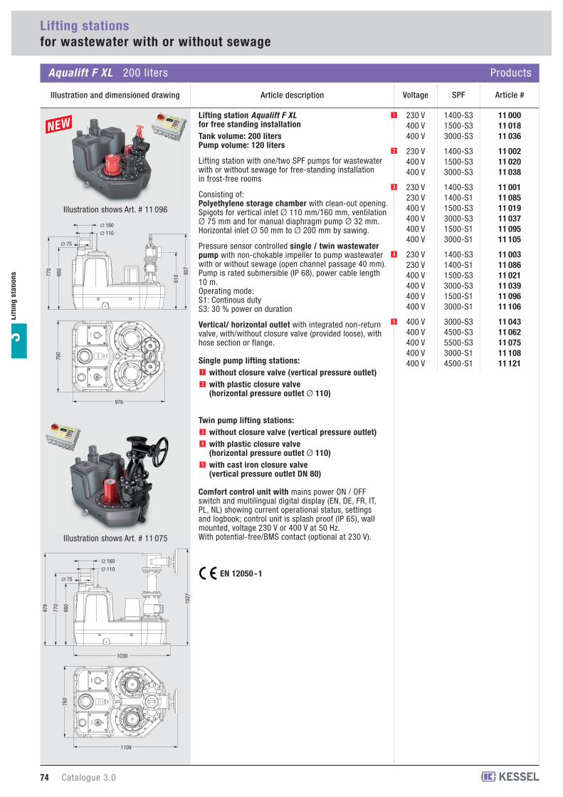
Lifting station Aqualift F XLfor free standing installationTank volume: 200 litersPump volume: 120 liters
Lifting station with one/two SPF pumps for wastewaterwith or without sewage for free-standing installation in frost-free rooms
Consisting of:Polyethylene storage chamber with clean-out opening. Spigots for vertical inlet Ø 110 mm/160 mm, ventilationØ 75 mm and for manual diaphragm pump Ø 32 mm.Horizontal inlet Ø 50 mm to Ø 200 mm by sawing.
Pressure sensor controlled single / twin wastewaterpump with non-chokable impeller to pump wastewaterwith or without sewage (open channel passage 40 mm).Pump is rated submersible (IP 68), power cable length10 m.Operating mode:S1: Continous dutyS3: 30 % power on duration
Vertical/ horizontal outlet with integrated non-returnvalve, with/without closure valve (provided loose), withhose section or flange.
Single pump lifting stations:without closure valve (vertical pressure outlet)with plastic closure valve(horizontal pressure outlet Ø 110)
Twin pump lifting stations:without closure valve (vertical pressure outlet)with plastic closure valve(horizontal pressure outlet Ø 110)with cast iron closure valve(vertical pressure outlet DN 80)
Comfort control unit with mains power ON / OFFswitch and multilingual digital display (EN, DE, FR, IT,PL, NL) showing current operational status, settingsand logbook; control unit is splash proof (IP 65), wallmounted, voltage 230 V or 400 V at 50 Hz.With potential-free/BMS contact (optional at 230 V).
1
2
3
4
5
11 00011 01811 036
11 00211 02011 038
11 00111 08511 01911 03711 09511 105
11 00311 08611 02111 03911 09611 106
11 04311 06211 07511 10811 121
1400-S31500-S33000-S3
1400-S31500-S33000-S3
1400-S31400-S11500-S33000-S31500-S13000-S1
1400-S31400-S11500-S33000-S31500-S13000-S1
3000-S34500-S35500-S33000-S14500-S1
230 V400 V400 V
230 V400 V400 V
230 V230 V400 V400 V400 V400 V
230 V230 V400 V400 V400 V400 V
400 V400 V400 V400 V400 V
Illustration shows Art. # 11 096
1030
1109
978
760
770
660 10
27
Ø 75
Ø 110
Ø 160
976
760
770
660
807
610
Ø 110
Ø 160
Ø 75
Illustration shows Art. # 11 075
Illustration and dimensioned drawing Article description
74 Catalogue 3.0
SPFVoltage Article #
EN 12050 - 1
1
3
4
5
2
11 01011 09011 02811 04611 10011 110
11 01211 09111 03011 04811 10111 111
11 05211 06711 08011 11311 124
1400-S31400-S11500-S33000-S31500-S13000-S1
1400-S31400-S11500-S33000-S31500-S13000-S1
3000-S34500-S35500-S33000-S14500-S1
230 V230 V400 V400 V400 V400 V
230 V230 V400 V400 V400 V400 V
400 V400 V400 V400 V400 V
SPFVoltage Article #
Aqualift F XL 300 liters Products
Lifting stationsfor wastewater with or without sewage
Lif
tin
gsta
tio
ns
3
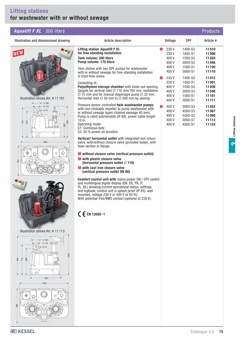
Lifting station Aqualift F XLfor free standing installationTank volume: 300 litersPump volume: 175 liters
Twin station with two SPF pumps for wastewaterwith or without sewage for free-standing installation in frost-free rooms
Consisting of:Polyethylene storage chamber with clean-out opening. Spigots for vertical inlet Ø 110 mm/160 mm, ventilationØ 75 mm and for manual diaphragm pump Ø 32 mm.Horizontal inlet Ø 50 mm to Ø 200 mm by sawing.
Pressure sensor controlled twin wastewater pumpswith non-chokable impeller to pump wastewater withor without sewage (open channel passage 40 mm).Pump is rated submersible (IP 68), power cable length10 m.Operating mode:S1: Continous dutyS3: 30 % power on duration
Vertical/ horizontal outlet with integrated non-returnvalve, with/without closure valve (provided loose), withhose section or flange.
without closure valve (vertical pressure outlet)with plastic closure valve(horizontal pressure outlet Ø 110)with cast iron closure valve(vertical pressure outlet DN 80)
Comfort control unit with mains power ON / OFF switchand multilingual digital display (EN, DE, FR, IT,PL, NL) showing current operational status, settingsand logbook; control unit is splash proof (IP 65), wallmounted, voltage 230 V or 400 V at 50 Hz.With potential-free/BMS contact (optional at 230 V).
3
4
5
800
889
994
1259
770
680 10
42
Ø 75
Ø 110
Ø 160
760
1260
770
679
806
609
Ø 75
Ø 110
Ø 160
EN 12050 - 1
Illustration and dimensioned drawing Article description
Catalogue 3.0 75
Illustration shows Art. # 11 101
Illustration shows Art. # 11 113
3
4
5

11 05411 115
11 05511 116
11 05711 07011 08311 127
3000-S33000-S1
3000-S33000-S1
3000-S34500-S35500-S34500-S1
400 V400 V
400 V400 V
400 V400 V400 V400 V
SPFVoltage Article #Article description
1000
1089
978
1260
770
680 10
27
Ø 75
Ø 110
Ø 160
Aqualift F XL 450 liters Products
Illustration and dimensioned drawing
76 Catalogue 3.0
Lifting stationsfor wastewater with or without sewage
Lif
tin
g s
tati
on
s3
Illustration shows Art. # 11 127
Lifting station Aqualift F XLfor free standing installationTank volume: 450 litersPump volume: 250 liters
Twin station with two SPF pumps for wastewaterwith or without sewage for free-standing installation in frost-free rooms
Consisting of:Polyethylene storage chamber, with air pressure leveldetector, clean-out opening. Spigots for vertical inlet Ø 110 mm/160 mm, ventilationØ 75 mm and for manual diaphragm pump Ø 32 mm.Horizontal inlet Ø 50 mm to Ø 200 mm by sawing.
Pressure sensor controlled twin wastewater pumpswith non-chokable impeller to pump wastewater withor without sewage (open channel passage 40 mm).Pump is rated submersible (IP 68), power cable length10 m.Operating mode:S1: Continous dutyS3: 30 % power on duration
Vertical/ horizontal outlet with integrated non-returnvalve, with/without closure valve (provided loose), withhose section or flange.
without closure valve (vertical pressure outlet)with plastic closure valve(horizontal pressure outlet Ø 110)with cast iron closure valve(vertical pressure outlet DN 80)
Comfort control unit with mains power ON / OFFswitch and multilingual digital display (EN, DE, FR, IT,PL, NL) showing current operational status, settingsand logbook; control unit is splash proof (IP 65), wallmounted, voltage 230 V or 400 V at 50 Hz.With potential-free/BMS contact (optional at 230 V).
EN 12050 - 1
3
4
5
3
4
5
20 40 60
5
10
15
20
25
SPF 5500
SPF 4500
SPF 3000
SPF 1500
SPF 1400
Q [m3/h]
H [m]
Qmin for Ø 90 mm*
Qmin for Ø 110 mm*
Lifting stationsfor wastewater with or without sewage
Lif
tin
gsta
tio
ns
3
Installation example Aqualift F XL Professional advantages
�
�
Additional inletconnections on-siteInlets from sizeØ 50 mm toØ 200 mminlets can be easily installed.
Polymer gate closure valves and fittingsfor SPF 1400, 1500, 3000 models.Cast iron gate closure valves and fittingsfor SPF 4500 and 5500 models.Cast iron systems also available for otherpump models where excessive returnpressures are expected
Compact dimensioned bodies offer largestorage capacities but still allow accessthrough 800 mm wide doorways.
Single or Twin Pump Lifting StationsIncludes digital display control unit andnon-return valve.
Inlet connectionSize Ø 110 mm orØ 160 mm selectedon-site
Ø 110
Ø 160
Catalogue 3.0 77
SPF 30003.2 kW2.7 kW400 V 5.4 A
S1
188 kg
SPF 45004.5 kW3.7 kW400 V 7.4 A
S1
189 kg
SPF 55005.7 kW4.7 kW400 V 9.1 A
S3 30 % power on duration
211 kg
SPF 15001.4 kW1.1 kW400 V 2.7 A
S1
98 kg
SPF 14001.6 kW1.1 kW230 V 7.3 A
S1
99 kg
TypeInput Power (P1)Power (P2)VoltageAmperage
Operating mode
Weight
* according to EN 12056-4
The wastewater is drained by the Aqualift F XL � lifting station fully automatically upwards viathe backwater loop to the sewage system. A greater pumping capacity if more wastewater occursis guaranteed by a second pump switching on automatically. Long pump service life thanks toalternating operation. The lifting stations of the Aqualift F XL series are particularly suitable forindustrial and municipal applications, such as downstream from a grease separator �.
Comfort control unitUser friendly navigation in multi-line displayWith self-diagnosis system SDS andmemory function for the next serviceDisplays current operational statusSimple setting of parameters relevant forthe functionOperating hours counterOptional forwarding of alarm and generalfault signals via a GSM interfaceMultilingual display (EN, DE, FR, IT, PL, NL)
400 Volt
230 Volt
0
101214161820
8
246
0 10 30 50 7020 40 60 80
SPF 2,6 SPF 4,8SPF 3,5
Q [m3/h]
H [m]Qmin for Ø 110 mm*
28 63828 63928 640
400 V400 V400 V
2.6 kW3.5 kW4.8 kW
EN 12050 - 1guaranteed with
tested quality
Type-testedand monitored
LGA
78 Catalogue 3.0
Lifting stationsfor wastewater with or without sewage
Aqualift F Duo XXL 750 liters Products
Illustration and dimensioned drawing Article description
Lif
tin
g s
tati
on
s3
18372000
1385
1296
985
1055
VoltagePower Article #
TypePower (P2)
Input Power (P1)
VoltageFrequencyAmperage
Cable connections
Media temperatureProtection
SPF260KE2.6 kW
3.3 kW
400 V 50 Hz5.6 A
5 m Length,7 x 1.5 mm2
40°CIP 68
SPF550KE4.8 kW
5.6 kW
400 V 50 Hz10.2 A
5 m Length,7 x 1.5 mm2
40°CIP 68
SPF400KE3.5 kW
4.2 kW
400 V 50 Hz8.2 A
5 m Length,7 x 1.5 mm2
40°CIP 68* according to EN 12056-4
Lifting station Aqualift F Duo XXL twin lifting station with closure valvefor wastewater with or without sewage(For use with grease separators size NS 10 and larger)for free standing installation in frost free areasConsists of:Polyethylene collection chambers,storage volume 750 liter, pumping volume 300 liter,twin 420 mm OD access / maintenance covers,Ø 160 inlet (Ø 200 available upon request), inletheight 1055 mm, ventilation connection size Ø 110.Pressure sensor controlled twin wastewater pumpswith macerating (cutting assembly) for pumpingwastewater with or without raw sewage, IP 68submersible pumps, Duty / Standby operation,10 meter power cable length. Vertical pressure outlet with Ø 110 connectionand flange, with closure valve and integratedbackflow preventer.Comfort control unit with mains power ON / OFFswitch and multilingual digital display (EN, DE, FR, IT,PL, NL) showing current operational status, settingsand logbook, IP 54 splash proof control unit housing, for wall mounting, operational voltage - 400 V DC, with potential free contact (BMS) connections.Total weight empty: approx 220 kg
Float switch resistant to fatty acids availableon request at no extra charge.

Article descriptionOuter diameter
Ø (mm) Article #
28 692-28 693-
28 05728 05828 059
---
Sound absorptionsound-absorbing underlay mat (10 mm thick)
for lifting stations Aqualift F Mono
for lifting stations Aqualift F Duo
for lifting stations Aqualift F XL
200 liter300 liter450 liter
28 683Ø 110
28 69828 699
Ø 110Ø 160
Closure valve for all lifting stations Aqualift F
Closure valve made of polymer for installation on inlet side (no pressure)for all lifting stations Aqualift F
28 68011/2 inchManual diaphragm pump 11/2 inchfor manually pumping wastewater.With a ball valve on inlet and outlet side
28 048-Compressor set for bubble formationfor use in combination with lifting stations andpumping stations with pressure control:
prevents soiling, compensates leaks, avoidscondensate forming in the pressure hose,makes operation of systems possible withpressure hose lengths > 10 m, includingconnection T-piece, including 10 m pressurehose.
850 114850 116850 117850 118850 119850 123
Ø 50Ø 75Ø 110Ø 125Ø 160Ø 200
Pipe sealing gasket(EPDM)Use KESSEL hole saw when drilling.
for lifting stations Aqualift F
50 100-
Hole sawfor drilling lateral surfaces for inlets and outlets
Ø 50, 75, 110, 125 and 160(Saw blade holder Ø = 190 mm)
50 102-
22
�
20 162-Audible alarm20 m cable length
suitable for all control units
80 072-Potential-free contactsuitable for all control units 230 V: Wastewater station Aqualift F, Lifting station Aqualift F Mono 230 V
Catalogue 3.0 79
Aqualift F / Aqualift F XL / Aqualift F Duo XXL Accessories
Illustration and dimensioned drawing
Lifting stations
Lif
tin
gsta
tio
ns
3
�
Ø 200(Use a drill with at least 1000 W)

Article descriptionOuter diameter
Ø (mm) Article #
28 06928 072
Ø 100Ø 120
Cast iron connection adaptorin cast iron
For connection from Aqualift F XLto on-site pressure pipe
For use with cast iron pressure pipes,with DIN 2501 flange PN 16, includes single gasket
28 068-Flange adaptor from DN 80 to DN 100in cast iron
Flange according to DIN 2501
For use with cast iron pressure pipes
28 66228 663
Ø 90Ø 110
28 66428 665
Ø 100Ø 120
Flexible pressure pipe connectionLength – 200 mm
for PE and SML pipe connections
For use with KESSEL Aqualift F, Aqualift F XL lifting stations
for cast iron pipe connections
For use with KESSEL Aqualift F XL lifting stations
28 018-Flange adaptor from DN 80 to DN 100 in PE, flanges according to DIN 2501
For use with PE and SML pressurepipes, includes two gaskets
28 01928 020
Ø 90Ø 110
Polyethylene connection adaptor in PE, for connection from Aqualift F XLto on-site pressure pipe
For use with PE and SML pressure pipes, with DIN 2501 flange, includes single gasket
28 021DN 80Backflow preventer in cast iron
with DN 80 flange according toDIN 2501; Backflow preventer withflap and flap opening lever
80 Catalogue 3.0
Lifting stations
Aqualift F XL Accessories
Illustration
Lif
tin
g s
tati
on
s3

28 794Antenna booster extension cablecable length 2.5 m
28 792TeleControl telemetric systemfor connection to KESSEL Comfort control units230 Volt and 400 Volt. Relaying of full text messages to up to threemobile phones. Without SIM card.
28 793
-
-
-TeleControl antenna boosterfor TeleControl telemetric systemincl. 2.5 m cable to improve reception.With magnetic base.
Article descriptionOuter diameter
Ø (mm) Article #
28 041DN 80Gate closure valve in cast iron
With DN 80 flange according to DIN 2501,gate closure valve including closure wheel
28 042Ø 80Y-Couplingin cast iron
With DN 80 flange according to DIN 2501, Y-coupling for use with Aqualift F XL twin pumplifting stations
28 04328 044
DN 80DN 100
Sealing gasket (rubber)according to DIN 2501
For pressure pipe connections
28 014-Alarm float switch upgrade setfor Aqualift F XL lifting stationFor use with 230 V and 400 V Comfort control units.Consists of float switch, support plate, cover and 5 meter connection cable.
28 015-Alarm float switch upgrade setfor Aqualift F and F Duo lifting stationsFor use with 230 V and 400 V Comfort control units.Consists of float switch, support plate, cover and 5 meter connection cable.
Aqualift F XL Accessories
Illustration
Lifting stations
Lif
tin
gsta
tio
ns
3
Catalogue 3.0 81
82 Catalogue 3.0
KESSEL-Product informationWastewater lifting station Aqualift S and Minilift
Lif
tin
g s
tati
on
s3
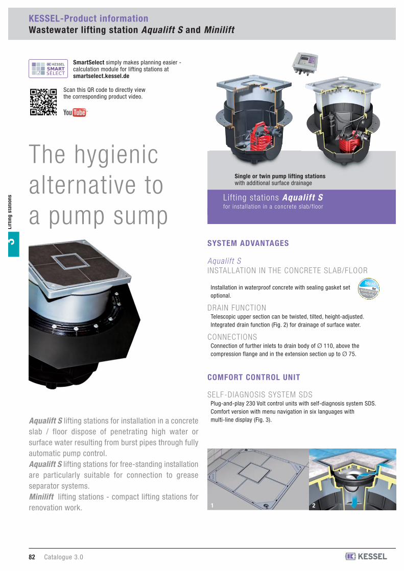
Aqualift S lifting stations for installation in a concreteslab / floor dispose of penetrating high water orsurface water resulting from burst pipes through fullyautomatic pump control.Aqualift S lifting stations for free-standing installationare particularly suitable for connection to greaseseparator systems.Minilift lifting stations - compact lifting stations forrenovation work.
Aqual i f t S INSTALLATION IN THE CONCRETE SLAB/FLOOR
Installation in waterproof concrete with sealing gasket setoptional.
DRAIN FUNCTIONTelescopic upper section can be twisted, tilted, height-adjusted.Integrated drain function (Fig. 2) for drainage of surface water.
CONNECTIONSConnection of further inlets to drain body of Ø 110, above thecompression flange and in the extension section up to Ø 75.
SYSTEM ADVANTAGES
Lift ing stat ions Aqualift Sfor instal lat ion in a concrete slab/f loor
1 2
Single or twin pump lifting stationswith additional surface drainage
SELF-DIAGNOSIS SYSTEM SDSPlug-and-play 230 Volt control units with self-diagnosis system SDS.Comfort version with menu navigation in six languages withmulti-line display (Fig. 3).
COMFORT CONTROL UNIT
waterproofconcrete
Idealwaterproofconcrete
Idealfor
SmartSelect simply makes planning easier -calculation module for lifting stations at smartselect.kessel.de
Scan this QR code to directly view the corresponding product video.
The hygienic alternative to a pump sump

Catalogue 3.0 83
Lif
tin
gsta
tio
ns
3
Lift ing stat ion Aqualift Sfor free-standing instal lat ion
3 54
Aqual i f t S FREE-STANDING INSTALLATION
Particularly suitable as a lifting station for connection to smallgrease separator systems (with maximum pumping height of 3 m).
LONG SERVICE LIFELong service life thanks to alternating operation.
SNAP CLOSUREPump removal without tool thanks to “one-handed snap closure”(Fig. 4), also suitable for mobile use.
CONNECTIONSConnection of further inlets Ø 50 and Ø 75.
Mini l i f t FREE-STANDING INSTALLATION /INSTALLATION IN CONCRETE SLAB/FLOOR
The mobile Minilift lifting station for free-standing installation fitsunder any sink; a washing machine, shower or other inlets can allbe connected at the same time.
SNAP CLOSUREPump removal without tool thanks to “one-handed snap closure”(Fig. 5), also suitable for mobile use.
FURTHER INLETSConnection of further inlets Ø 50 and Ø 75 directly on site.
FLEXIBLE INSTALLATIONRecessed installation in the concrete slab/floor up to 220 mmoptional.
Twin pump systemfor connection downstream from small grease separator systems
Single pump systemsIdeal for renovation work
SELF-DIAGNOSIS SYSTEM SDSPlug-and-play 230 Volt control units with self-diagnosis system SDS.Comfort version with menu navigation in six languages withmulti-line display (Fig. 3).
COMFORT CONTROL UNIT
Lift ing stat ions Miniliftfor free-standing instal lat ion / instal lat ion in concrete slab/f loor
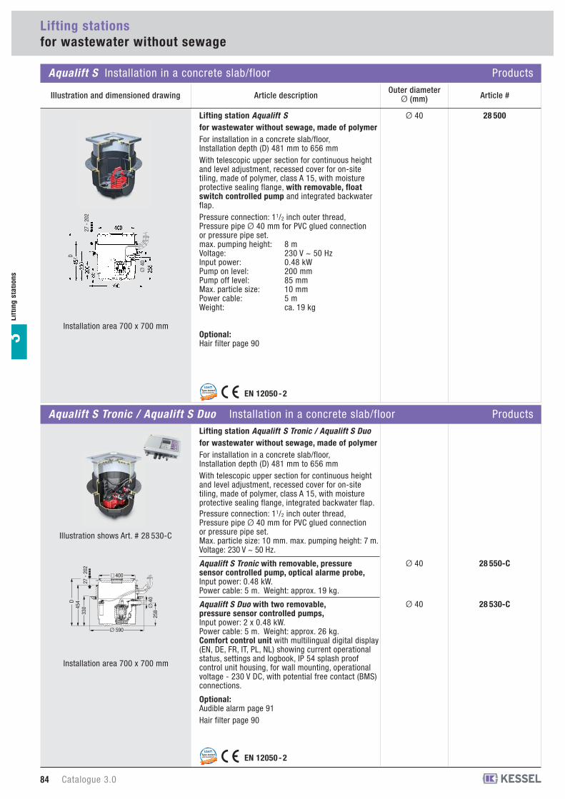
Article descriptionOuter diameter
Ø (mm) Article #
28 500Ø 40
28 550-CØ 40
28 530-CØ 40
Lifting station Aqualift S for wastewater without sewage, made of polymerFor installation in a concrete slab/floor, Installation depth (D) 481 mm to 656 mmWith telescopic upper section for continuous heightand level adjustment, recessed cover for on-sitetiling, made of polymer, class A 15, with moistureprotective sealing flange, with removable, floatswitch controlled pump and integrated backwaterflap.Pressure connection: 11/2 inch outer thread, Pressure pipe Ø 40 mm for PVC glued connectionor pressure pipe set.max. pumping height: 8 mVoltage: 230 V ~ 50 HzInput power: 0.48 kWPump on level: 200 mmPump off level: 85 mmMax. particle size: 10 mmPower cable: 5 mWeight: ca. 19 kg
Optional:Hair filter page 90
EN 12050 - 2guaranteed with
tested quality
Type-testedand monitored
LGA
EN 12050 - 2guaranteed with
tested quality
Type-testedand monitored
LGA
Installation area 700 x 700 mm
Installation area 700 x 700 mm
84 Catalogue 3.0
Lifting stationsfor wastewater without sewage
Aqualift S Installation in a concrete slab/floor Products
Illustration and dimensioned drawing
Lifting station Aqualift S Tronic / Aqualift S Duo for wastewater without sewage, made of polymerFor installation in a concrete slab/floor, Installation depth (D) 481 mm to 656 mmWith telescopic upper section for continuous heightand level adjustment, recessed cover for on-sitetiling, made of polymer, class A 15, with moistureprotective sealing flange, integrated backwater flap.Pressure connection: 11/2 inch outer thread, Pressure pipe Ø 40 mm for PVC glued connection or pressure pipe set.Max. particle size: 10 mm. max. pumping height: 7 m.Voltage: 230 V ~ 50 Hz.
Aqualift S Tronic with removable, pressuresensor controlled pump, optical alarme probe,Input power: 0.48 kW. Power cable: 5 m. Weight: approx. 19 kg.
Aqualift S Duo with two removable, pressure sensor controlled pumps,Input power: 2 x 0.48 kW. Power cable: 5 m. Weight: approx. 26 kg. Comfort control unit with multilingual digital display(EN, DE, FR, IT, PL, NL) showing current operationalstatus, settings and logbook, IP 54 splash proofcontrol unit housing, for wall mounting, operationalvoltage - 230 V DC, with potential free contact (BMS)connections.
Optional:Audible alarm page 91Hair filter page 90
Lif
tin
g s
tati
on
s3
Aqualift S Tronic / Aqualift S Duo Installation in a concrete slab/floor Products
258
Ø 590
Ø 4
0
33045
4D
400
27 -
202
Illustration shows Art. # 28 530-C
Ø 4
0
D
27 -
202
Catalogue 3.0 85
Lif
tin
gsta
tio
ns
3
Lifting stationsfor wastewater without sewage
Installation example Aqualift S Professional advantages
�
�
12345
76
1 2 3 4 5 6 7
H [m]
Q [m3/h]
Current type
Alternatingcurrent
Voltage
230 V
Current
2.12 A
Power P1 / P2
480 W / 320 W
RPM
2800 min-1
Motor protectionintegrated
Plug
Schuko5 m cable
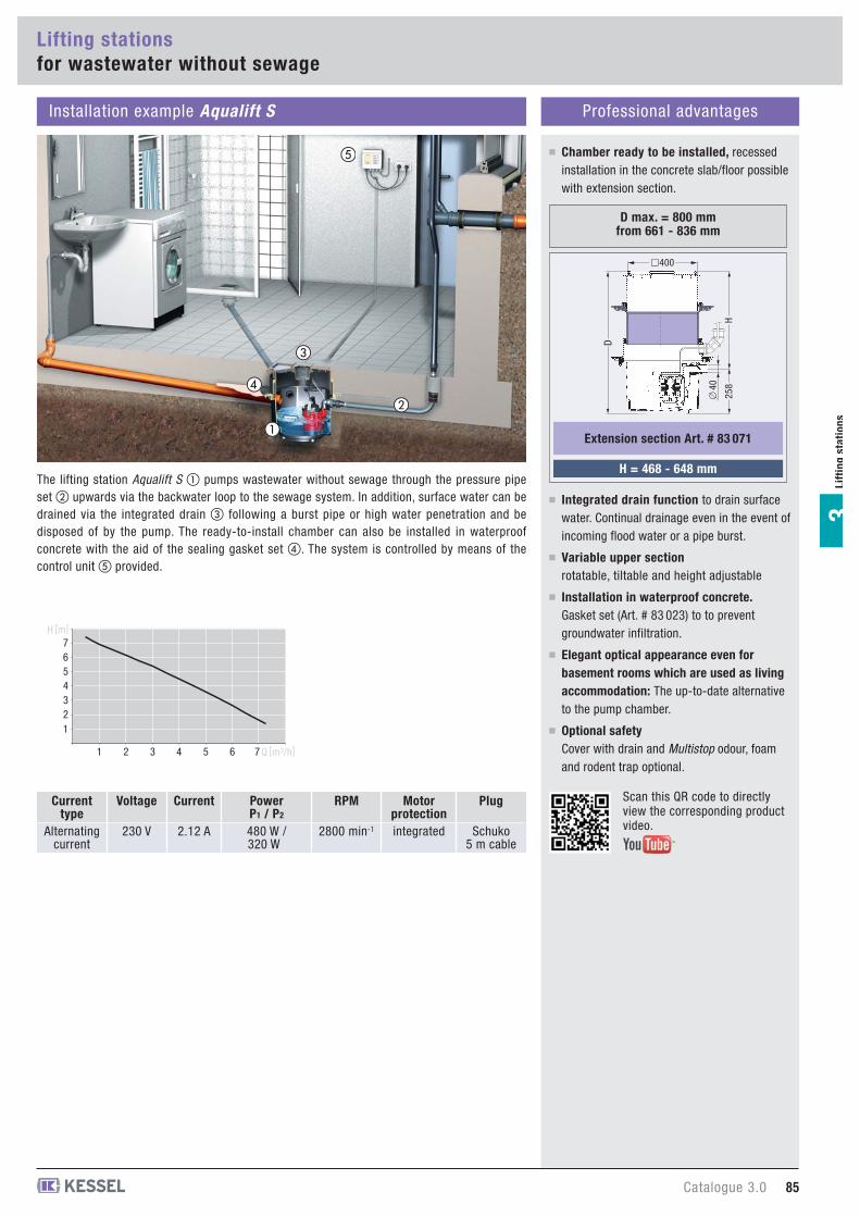
D max. = 800 mmfrom 661 - 836 mm
258
� 4
0
�400
H
H = 468 - 648 mm
Extension section Art. # 83 071
D
The lifting station Aqualift S � pumps wastewater without sewage through the pressure pipeset � upwards via the backwater loop to the sewage system. In addition, surface water can bedrained via the integrated drain � following a burst pipe or high water penetration and bedisposed of by the pump. The ready-to-install chamber can also be installed in waterproofconcrete with the aid of the sealing gasket set �. The system is controlled by means of thecontrol unit � provided.
Variable upper sectionrotatable, tiltable and height adjustable
Installation in waterproof concrete.Gasket set (Art. # 83 023) to to preventgroundwater infiltration.
Elegant optical appearance even forbasement rooms which are used as livingaccommodation: The up-to-date alternativeto the pump chamber.
Optional safetyCover with drain and Multistop odour, foamand rodent trap optional.
�
�
�
Chamber ready to be installed, recessedinstallation in the concrete slab/floor possiblewith extension section.
Integrated drain function to drain surfacewater. Continual drainage even in the event ofincoming flood water or a pipe burst.
Scan this QR code to directly view the corresponding product video.
Article descriptionOuter diameter
Ø (mm) Article #
86 Catalogue 3.0
Lifting stationsfor wastewater without sewage
Lif
tin
g s
tati
on
s3
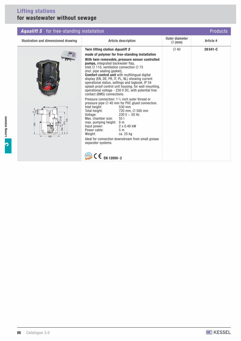
28 541-CØ 40Twin lifting station Aqualift Smade of polymer for free-standing installationWith twin removable, pressure sensor controlledpumps, integrated backwater flap, Inlet Ø 110, ventilation connection Ø 75 (incl. pipe sealing gasket), Comfort control unit with multilingual digitaldisplay (EN, DE, FR, IT, PL, NL) showing currentoperational status, settings and logbook, IP 54splash proof control unit housing, for wall mounting,operational voltage - 230 V DC, with potential freecontact (BMS) connections.Pressure connection: 11/2 inch outer thread or pressure pipe Ø 40 mm for PVC glued connection.Inlet height: 530 mmTotal height: 720 mm, Ø 500 mmVoltage: 230 V ~ 50 HzMax. chamber size: 55 lmax. pumping height: 8 mInput power: 2 x 0.48 kWPower cable: 5 mWeight: ca. 25 kgIdeal for connection downstream from small greaseseparator systems.
500
Ø 110
530
Ø 4
025
857
5 720
Aqualift S for free-standing installation Products
Illustration and dimensioned drawing
guaranteed with
tested quality
Type-testedand monitored
LGA
EN 12050 - 2
Lifting stationsfor wastewater without sewage
Lif
tin
gsta
tio
ns
3
Catalogue 3.0 87
Installation example Aqualift S Professional advantages
�
�
Current type
Alternatingcurrent
Voltage
230 V
Current
2.12 A
Power P1 / P2
480 W / 320 W
RPM
2800 min-1
Motor protectionintegrated
Plug
Schuko5 m cable
12345
76
1 2 3 4 5 6 7
H [m]
Q [m3/h
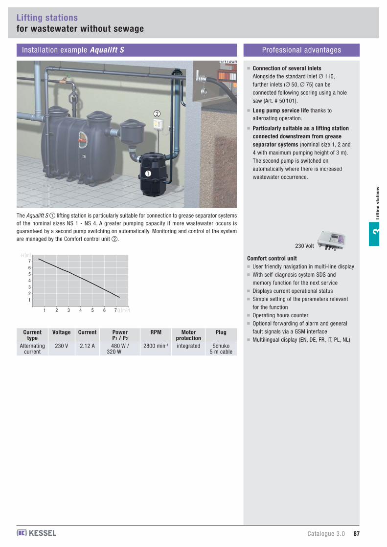
Particularly suitable as a lifting stationconnected downstream from greaseseparator systems (nominal size 1, 2 and4 with maximum pumping height of 3 m).The second pump is switched onautomatically where there is increasedwastewater occurrence.
Connection of several inletsAlongside the standard inlet Ø 110,further inlets (Ø 50, Ø 75) can beconnected following scoring using a holesaw (Art. # 50 101).
Long pump service life thanks toalternating operation.
The Aqualift S � lifting station is particularly suitable for connection to grease separator systemsof the nominal sizes NS 1 - NS 4. A greater pumping capacity if more wastewater occurs isguaranteed by a second pump switching on automatically. Monitoring and control of the systemare managed by the Comfort control unit �.
Comfort control unitUser friendly navigation in multi-line displayWith self-diagnosis system SDS andmemory function for the next serviceDisplays current operational statusSimple setting of the parameters relevantfor the functionOperating hours counterOptional forwarding of alarm and generalfault signals via a GSM interfaceMultilingual display (EN, DE, FR, IT, PL, NL)
230 Volt
Lifting station Miniliftmade of polymer for underground installationWith removable, float switch controlled pump andbackwater flap. Certified for wastewater.Pressure connection: 11/2 inch outer thread or pressure pipe Ø 40 mm for PVC glued connectionPumping height: 6 mVoltage: 230 V ~ 50 HzInput power: 0.34 kWPower cable: 5 mMax. particle size: 10 mmPump on level: 180 mmPump off level: 80 mmWith activated charcoal filter
Minilift for free-standing installation Products
Article descriptionOuter diameter
Ø (mm) Article #
88 Catalogue 3.0
Lifting stationsfor wastewater without sewage
Lif
tin
g s
tati
on
s3
28 570Ø 40
28 560Ø 40
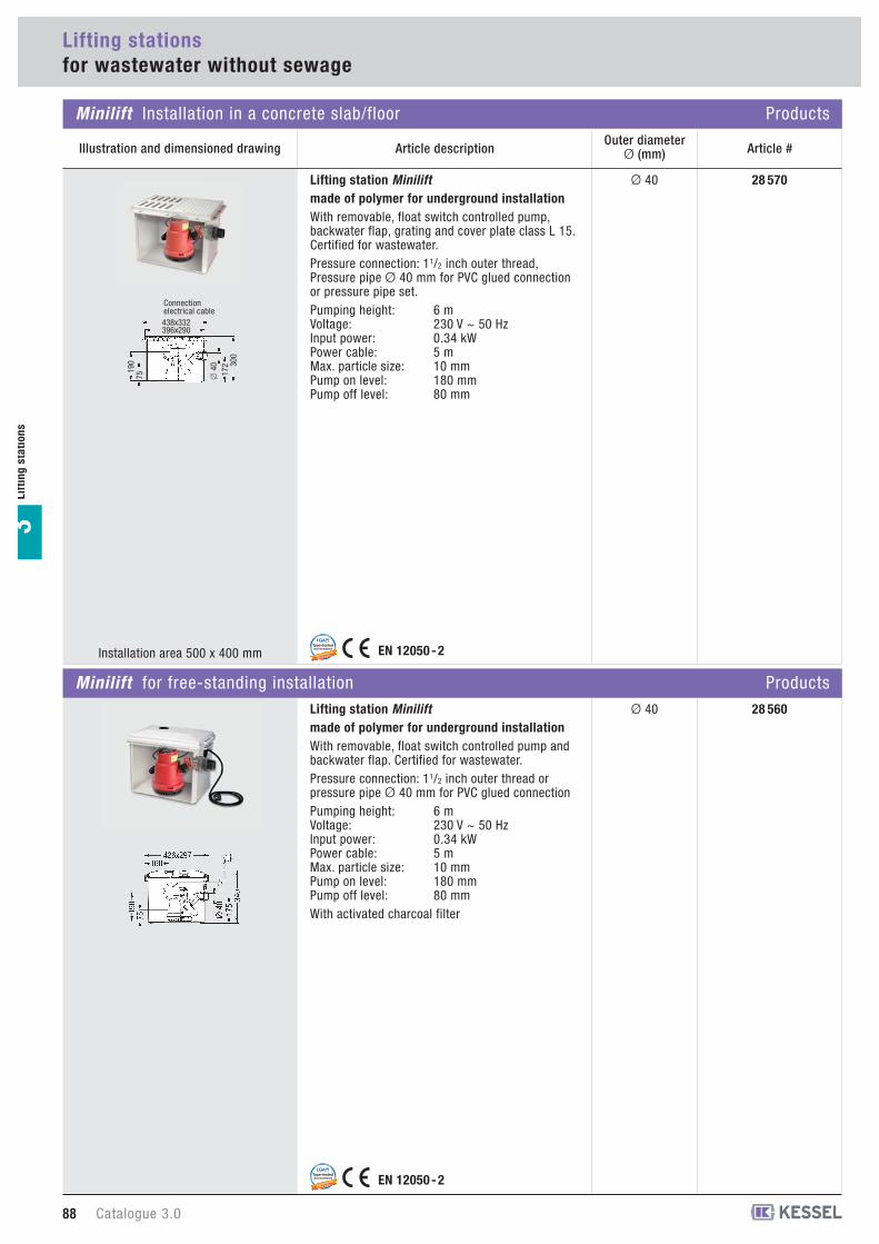
Lifting station Miniliftmade of polymer for underground installationWith removable, float switch controlled pump,backwater flap, grating and cover plate class L 15.Certified for wastewater.Pressure connection: 11/2 inch outer thread, Pressure pipe Ø 40 mm for PVC glued connectionor pressure pipe set.Pumping height: 6 mVoltage: 230 V ~ 50 HzInput power: 0.34 kWPower cable: 5 mMax. particle size: 10 mmPump on level: 180 mmPump off level: 80 mm
EN 12050 - 2guaranteed with
tested quality
Type-testedand monitored
LGA
EN 12050 - 2guaranteed with
tested quality
Type-testedand monitored
LGA
Installation area 500 x 400 mm
Minilift Installation in a concrete slab/floor Products
Illustration and dimensioned drawing
438x332396x290
190
75 172 30
0
� 4
0
Connectionelectrical cable
Catalogue 3.0 89
Lif
tin
gsta
tio
ns
3
Installation example Minilift Professional advantages
� �
Current type
Alternatingcurrent
Voltage
230 V
Current
2.27 A
RPM
2800 min-1
Motor protectionintegrated
Plug
Schuko5 m cable
Chamber ready to be installed, recessedinstallation in the concrete slab/floorpossible with extension section (Art. # 32 500).
Integrated drain function to drain surfacewater. Continual drainage even in the eventof incoming flood water or a pipe burst.
Tool-free pump removalThe “one-hand snap closure” featuremeans that no tools are required to removethe pump for cleaning and maintenance.
�
1
2
3
4
5
1 2 3 4 5 6 Q [m3/h]
H [m]
Installation example Minilift Professional advantages
�
�
Current type
Alternatingcurrent
Voltage
230 V
Current
2.27 A
RPM
2800 min-1
Motor protectionintegrated
Plug
Schuko5 m cable
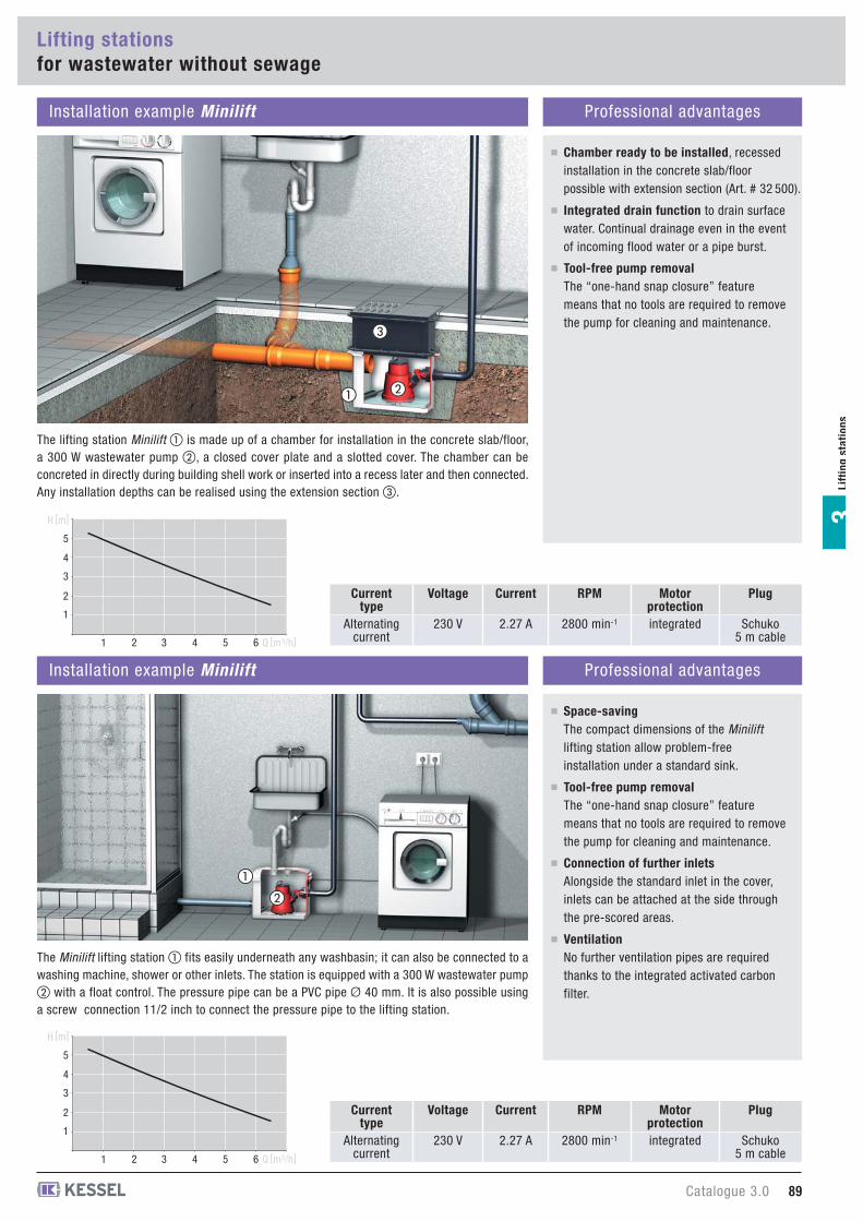
Tool-free pump removalThe “one-hand snap closure” featuremeans that no tools are required to removethe pump for cleaning and maintenance.
Connection of further inletsAlongside the standard inlet in the cover,inlets can be attached at the side throughthe pre-scored areas.
VentilationNo further ventilation pipes are requiredthanks to the integrated activated carbonfilter.
1
2
3
4
5
1 2 3 4 5 6 Q [m3/h]
H [m]
Space-savingThe compact dimensions of the Minilift
lifting station allow problem-freeinstallation under a standard sink.
The lifting station Minilift � is made up of a chamber for installation in the concrete slab/floor,a 300 W wastewater pump �, a closed cover plate and a slotted cover. The chamber can beconcreted in directly during building shell work or inserted into a recess later and then connected.Any installation depths can be realised using the extension section �.
The Minilift lifting station � fits easily underneath any washbasin; it can also be connected to awashing machine, shower or other inlets. The station is equipped with a 300 W wastewater pump� with a float control. The pressure pipe can be a PVC pipe Ø 40 mm. It is also possible usinga screw connection 11/2 inch to connect the pressure pipe to the lifting station.
Lifting stationsfor wastewater without sewage
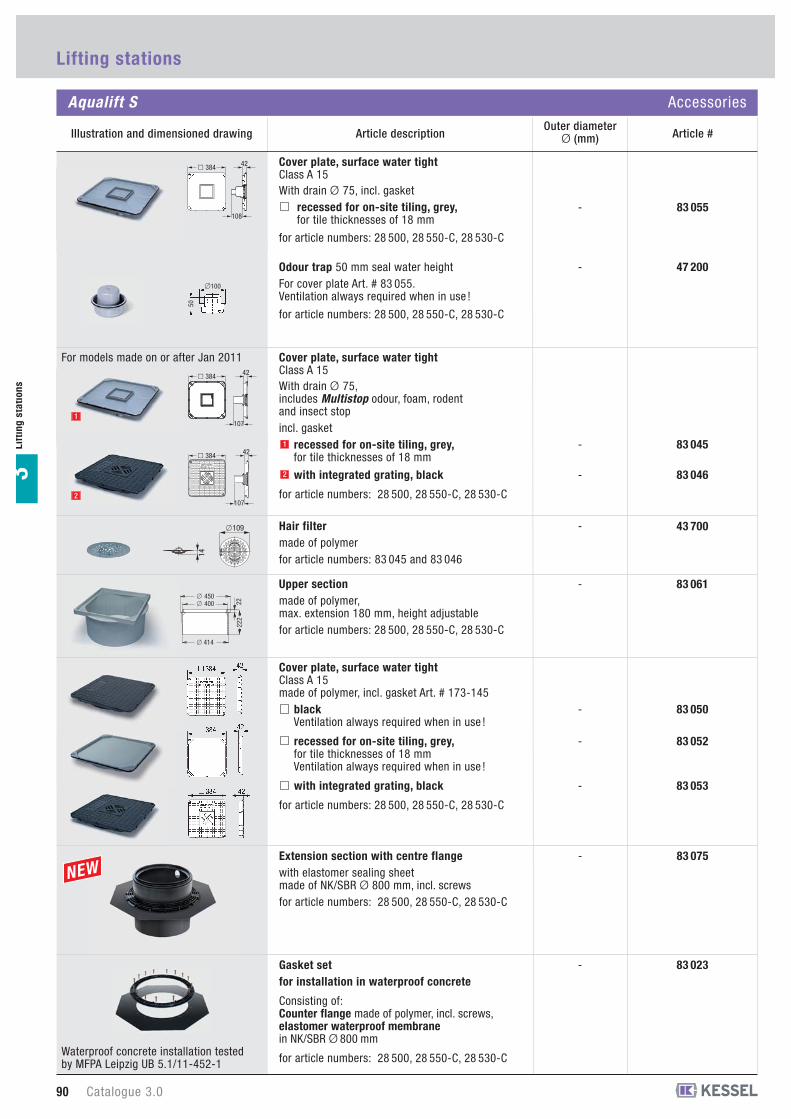
83 075-Extension section with centre flangewith elastomer sealing sheet made of NK/SBR Ø 800 mm, incl. screwsfor article numbers: 28 500, 28 550-C, 28 530-C
Article descriptionOuter diameter
Ø (mm) Article #
83 023-Gasket setfor installation in waterproof concrete
Consisting of:Counter flange made of polymer, incl. screws, elastomer waterproof membranein NK/SBR Ø 800 mm
for article numbers: 28 500, 28 550-C, 28 530-C
83 050
83 052
-
-
83 053-
Cover plate, surface water tightClass A 15made of polymer, incl. gasket Art. # 173-145
blackVentilation always required when in use !
recessed for on-site tiling, grey,for tile thicknesses of 18 mmVentilation always required when in use !
with integrated grating, black
for article numbers: 28 500, 28 550-C, 28 530-C
83 061-Upper sectionmade of polymer, max. extension 180 mm, height adjustablefor article numbers: 28 500, 28 550-C, 28 530-C
414
450 400 22
222
�
��
43 700-Hair filtermade of polymerfor article numbers: 83 045 and 83 04614
�109
83 055-
Cover plate, surface water tightClass A 15With drain Ø 75, incl. gasket
recessed for on-site tiling, grey,for tile thicknesses of 18 mm
for article numbers: 28 500, 28 550-C, 28 530-C
� 384 42
108
47 200-Odour trap 50 mm seal water heightFor cover plate Art. # 83 055.Ventilation always required when in use !
for article numbers: 28 500, 28 550-C, 28 530-C
50
�100
83 045-
83 046-
Cover plate, surface water tightClass A 15With drain Ø 75, includes Multistop odour, foam, rodent and insect stopincl. gasket
recessed for on-site tiling, grey,for tile thicknesses of 18 mm
with integrated grating, black
for article numbers: 28 500, 28 550-C, 28 530-C
For models made on or after Jan 2011
1
2
2
1
� 384 42
107
� 384 42
107
Waterproof concrete installation testedby MFPA Leipzig UB 5.1/11-452-1
90 Catalogue 3.0
Lifting stations
Aqualift S Accessories
Illustration and dimensioned drawing
Lif
tin
g s
tati
on
s3

83 071-Extension section with flangemade of polymer, max. extension 180 mmFor gasket set Art. # 83 023for article numbers: 28 500, 28 550-C, 28 530-C
When multiple extension sections are used makesure that access to valve is still possible !
�41440
230
180
�59010Article description
Outer diameterØ (mm) Article #
50 101-Hole saw Ø 50, 75, 110(Saw blade holder Ø = 145 mm)
50 100-Hole saw Ø 50, 75, 110, 125 and 160(Saw blade holder Ø = 190 mm)
28 040Ø 40Pressure pipe setincl. 5 m pressure pipe hose Ø 40
for article numbers: 28 500, 28 550-C, 28 530-C
80 072-Potential-free contactsuitable for all control units with SDS function: Aqualift S Tronic
20 162-Audible alarm20 m cable length
suitable for all control units with SDS function: Aqualift S Tronic
20 221-
20 220-Alarm
with electrode probe
with optical probe
for article numbers: 28 500
850 114850 116850 117850 118850 119
Ø 50Ø 75Ø 110Ø 125Ø 160
Pipe sealing gasket(EPDM)Use KESSEL hole saw when drilling.
for article numbers: 28 500, 28 550-C, 28 530-C, 28 560, 28 541-C
22
�
170
196
65
182
30 003 W
30 003 S
-
-
Cover plate Class A 15 grey
black
for article numbers: 28 570
30 001W
30 001S
-
-
Cover with grating Class A 15grey
black
for article numbers: 28 570
83 070-Extension section made of polymer, max. extension 180 mm, incl. gasketfor article numbers: 28 500, 28 550-C, 28 530-C
When multiple extension sections are used makesure that access to valve is still possible !
480
414
150
200
�
�
32 500-Extension section made of polymerHeight = 220 mm for deep installation
for article numbers: 28 570
Catalogue 3.0 91
Aqualift S / Minilift Accessories
Illustration and dimensioned drawing
Lifting stations
Lif
tin
gsta
tio
ns
3
�
�
92 Catalogue 3.0
KESSEL-Product informationPumping stations Aqualift F and Aqualift S
Lif
tin
g s
tati
on
s3
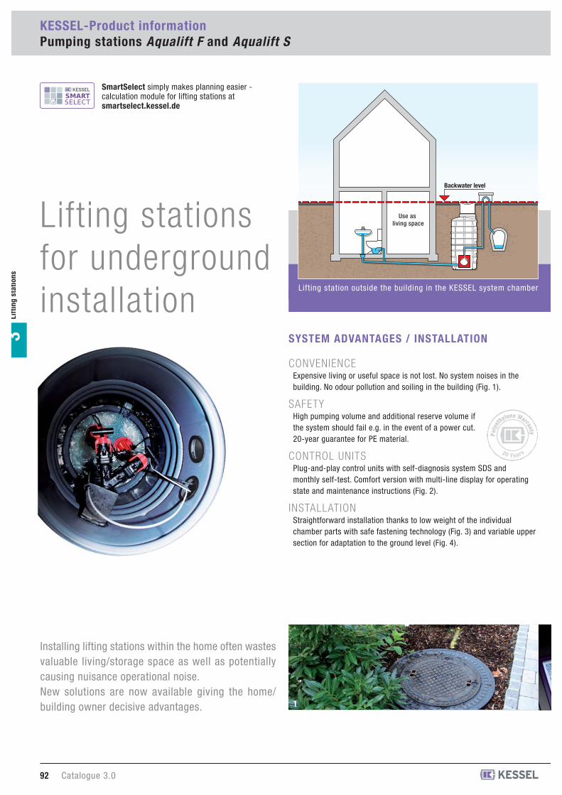
Installing lifting stations within the home often wastesvaluable living/storage space as well as potentiallycausing nuisance operational noise.New solutions are now available giving the home/building owner decisive advantages.
CONVENIENCEExpensive living or useful space is not lost. No system noises in thebuilding. No odour pollution and soiling in the building (Fig. 1).
SAFETYHigh pumping volume and additional reserve volume ifthe system should fail e.g. in the event of a power cut.20-year guarantee for PE material.
CONTROL UNITSPlug-and-play control units with self-diagnosis system SDS andmonthly self-test. Comfort version with multi-line display for operatingstate and maintenance instructions (Fig. 2).
INSTALLATIONStraightforward installation thanks to low weight of the individualchamber parts with safe fastening technology (Fig. 3) and variable uppersection for adaptation to the ground level (Fig. 4).
SYSTEM ADVANTAGES / INSTALLATION
1
Use as living space
Backwater level
Poly
et
hylene Warranty Poly
et
hylene Warranty
20 Years
Lifting station outside the building in the KESSEL system chamber
SmartSelect simply makes planning easier -calculation module for lifting stations at smartselect.kessel.de
Lifting stationsfor undergroundinstallation

Catalogue 3.0 93
Lif
tin
gsta
tio
ns
3
Pumping stat ion Aqualift Ffor wastewater with or without sewage
Pumping stat ion Aqualift Sfor wastewater without sewage /rain water
Li f t ing stat ion Aqualift Ffor wastewater with or without sewage
Komfort chamber system Ø 1000
2 43
LIFTING / PUMPING STATIONS
SELECTION CRITERIA
Pumping stationAqualift S Ø 1000
Pumping stationAqualift S Ø 600
Pumping stationAqualift F Ø 1000
Pumping stationAqualift F Ø 800/1000
Pumping stationAqualift F Ø 600
Lifting stationAqualift F Ø 1000
989695Products see page 100 102 104
Wastewater
Power (P2)
ATEX*
Pump
Pressure pipeconnection Ø
Installation depth
Pumping height
with sewage
1.1 / 2.2 kW
-
SPF 1400 - 3000
110 mm
1630 - 5130 mm
7 / 16 m
with sewage
0.6 kW
-
SPZ 1000
40 mm
800 - 2250 mm
9 m
with sewage
0.75 kW
-
AP 501
63 / 90 mm
1480 - 3130 mm
11 m
without sewage
0.3 / 0.7 kW
-
KTP 500 / GTF 1000
40 mm
800 - 2250 mm
7 / 9 m
without sewage
0.3 / 0.7 kW
-
KTP 500 / GTF 1000
40 mm
1630 - 5130 mm
7 / 9 m
with sewage
1.3 / 1.9 kW
P
TPF
63 / 90 mm
1630 - 5130 mm
15 / 30 m
* The product is suitable for installation in potentially explosive atmospheres
Komfort chamber system Ø 600 / 800 / 1000 Komfort chamber system Ø 600 / 1000

867 611 D867 621 D
866 611 D866 621 D866 631 D866 641 D866 651 D
866 711 D866 721 D866 731 D866 741 D866 751 D866 761 D866 771 D
868 661 D868 671 D
868 611 D868 621 D868 631 D868 641 D868 651 D
868 711 D868 721 D868 731 D868 741 D868 751 D868 761 D868 771 D
867 611 B867 621 B
866 611 B866 621 B866 631 B866 641 B866 651 B
866 711 B866 721 B866 731 B866 741 B866 751 B866 761 B866 771 B
868 661 B868 671 B
868 611 B868 621 B868 631 B868 641 B868 651 B
868 711 B868 721 B868 731 B868 741 B868 751 B868 761 B868 771 B
D1: 230 VD2: 230 V
D1: 400 VD2: 400 VD3: 400 VD4: 400 VD5: 400 V
D1: 400 VD2: 400 VD3: 400 VD4: 400 VD5: 400 VD6: 400 VD7: 400 V
D1: 230 VD2: 230 V
D1: 400 VD2: 400 VD3: 400 VD4: 400 VD5: 400 V
D1: 400 VD2: 400 VD3: 400 VD4: 400 VD5: 400 VD6: 400 VD7: 400 V
Lifting station Aqualift Fin Komfort inspection chamber system Ø 1000 in PE-HDSingle station/twin stationfor wastewater with or without sewagewith closure valveFor underground installation(dry installation)
Single station
Twin station
Cover plate class A/B (Version B)Cover plate class D (Version D)
Lifting station with PE storage chamber, Chamber volume Mono approx. 50 liters/
Duo approx. 120 litersPumping volume Mono approx. 20 liters/
Duo approx. 50 literswith clean-out opening.Connection coupling for inlet Ø 110 (Inlet height Mono 180 mm / Duo 310 mm) andfor ventilation Ø 75, Mono 525 mm /Duo 625 mmConnection coupling for manual diaphragmpump Ø 32.Pressure sensor controlled wastewater pumpwith non-chokable impeller to pump wastewaterwith or without sewage (open channel passage40 mm). Pump is rated submersible (IP 68),power cable length 10 m. Horizontal pressure outlet with integratedbackwater flap, connection coupling Ø 110Mono 565 mm / Duo 615 mm hose section andclosure valve.Comfort control unit with mains power ON / OFFswitch and multilingual digital display (EN, DE,FR, IT, PL, NL) showing current operational status,settings and logbook; control unit is splash proof(IP 65), wall mounted, voltage 230 / 400 V at50 Hz. With potential-free contact.Ready mounted in theInspection chamber system Ø 1000 in PE-HD,incl. access steps, water-tight, with continuousheight and level adjustment, cover class A/B, Din cast iron according to EN 124, inlet Ø 110,cable conduit connection Ø 110,Installation depth from 1.5 to 5 m (see table),Pressure pipe Ø 110 ready mounted with closure valve.
Handles groundwater depths up to 500 mm(greater groundwater resistance on request)
Continuous duty pumps (S1) on requestAccessories see page 112
Lifting stationsfor underground installation according to EN 752
Lifting station Aqualift F Ø 1000 Products
Illustration and dimensioned drawing Article description
Lif
tin
g s
tati
on
s3
Article #Class D
Article #Class BVoltage
PumpSPF
14001400
15001500150015001500
3000300030003000300030003000
14001400
15001500150015001500
3000300030003000300030003000
1
2
180
Mono
310
Duo
525 Mono
625 Duo
565 Mono615 Duo
Vent
ilatio
n /
cabl
e pi
ping
�11
0
Vent
ilatio
nIn
let
Pres
sure
pip
e �
110
Inst
alla
tion
dept
hs D
1
2
D 1D 2D 3D 4D 5D 6D 7
Installation depths (D):1630 - 2130 mm2130 - 2630 mm2630 - 3130 mm3130 - 3630 mm3630 - 4130 mm4130 - 4630 mm4630 - 5130 mm
D
EN 12050 - 1
94 Catalogue 3.0

Lif
tin
gsta
tio
ns
3
Installation example lifting station Aqualift F Ø 1000 Professional advantages
Comfort control unit with mains power ON / OFFswitch and multilingual digitaldisplay (EN, DE, FR, IT, PL, NL) showingcurrent operational status, settings andlogbook
SPF 30002.7 kW3.2 kW400 V 50 Hz5.4 A
3x16A surge-proof10 m Length,7 x 1.5 mm2
35°C31 kgIP 68
S330 % power on duration
SPF 15001.1 kW1.4 kW400 V 50 Hz2.7 A
3x16A surge-proof10 m Length,7 x 1.5 mm2
35°C30 kgIP 68
S360 % power on duration
SPF 14001.1 kW1.6 kW230 V 50 Hz7.3 A
16 A surge-proof10 m Length,7 x 1.5 mm2
35°C30 kgIP 68
S360 % power on duration
TypePower (P2)Input Power (P1)VoltageFrequencyAmperageFusesCable connectionsMedia temperatureWeight (Pump)Protection
Operating mode
1234567
10 20 30
SPF 1500
Q [m3/h]
H [m]
SPF 1400
Qmin for Ø 90 mm*
Qmin for Ø 110 mm*
2468
10121416
10 20 30 40
SPF 3000
H [m]
Q [m3/h]
Qmin for Ø 90 mm*
Qmin for Ø 110 mm*
* according to EN 12056-4
Variable upper sectioninclinable and and height adjustablefrom 100 to 600 mm
Simple to assemble with light-weightinspection chamber components and easyconnection technique.
Quick to mount with a high level ofpre-fabrication (bottom part of inspectionchamber with pressure pipe) and easyconnection using fixed couplings for inletand pressure pipe and bores with lipgaskets for ventilation and cable piping.
Long-term reliability with an absolutewater-tight inspection chamber systemwhich is resistant to sedimentary depositsand aggressive media as well as rootinfiltration.
Clean and straightforward maintenanceand repair work thanks to the closedpump tank.
Fully automated operation with anelectrical control unit with manual, offand automatic mode, optical and audiblewarning and alarm notification, detailedoperation and warning display, integratedpump rotation check, anti-blockingfunction, variable pump on and pumpoff settings.
Ideal for use with short pressure pipes(single system approx. 10 m, doublesystem approx. 20 m).
The wastewater does not remain in thetank for long, thus avoiding decompositionand outgassing.
Domestic wastewater from toilets and drainage fixtures flows with natural gradient to the Komfortchamber � and is pumped by the integrated Aqualift F � lifting station via the backwater loopto a higher-level sewage channel. The pressure pipe � should always be laid frost-free. TheComfort control unit takes over the fully automatic pump control from within the building.
�
�
�400 Volt 230 Volt
Lifting stationsfor underground installation according to EN 752
Catalogue 3.0 95

Pumping stationsfor underground installation according to EN 752
Pumping station Aqualift F Ø 600 Products
Lif
tin
g s
tati
on
s3
EN 12050 (max 2 WC connections)
827 710 B827 720 B827 730 B
827 711 B827 721 B827 731 B
826 711 B826 721 B826 731 B
827 710 D827 720 D827 730 D
827 711 D827 721 D827 731 D
826 711 D826 721 D826 731 D
D1:D2:D3:
D1:D2:D3:
D1:D2:D3:
Pumping station Aqualift F with macerating / cutting pumpsin inspection chamber system Ø 600 in PE-LLDSingle station/twin stationfor wastewater with or without sewageFor underground installation
SPZ 1000 float switch controlled, removeablepump, plug in ready (230 V / 50Hz)
SPZ 1000 pressure sensor controlled, removablepump, IP 54 SDS control unit (230 V / 50Hz)
SPZ 1000 pressure sensor controlled, removabletwin pumps, IP 54 SDS control unit (230 V / 50Hz)
Cover plate class A/B (Version B)Cover plate class D (Version D)
Resistant to aggressive media, upper section made of polymer, vertically adjustable, cover class A/B, D in cast iron according to EN 124. Groundwater resistant. Inlet Ø 160, connection forpipe gasket for Ø 110 according to EN 1401 andEN 12666-1 - each for ventilation or conduit pipe.Note: Consider frost free depth of pressure pipe.Pressure pipe Ø 40 mm outside diameter for PVC glue connection, with integrated non-return flap. Current: 230 V ~ 50 Hz. Power cable length: 10 m.
For installations without explosion proof requirements
Handles groundwater depths up to 2000 mm
Illustration and dimensioned drawing Article description
1
2
3
Article #Class D
Article #Class B
Installationdepths
1
2
3
Ø860
700
/ 120
0 / 1
700
400
Inst
alla
tion
dept
hs D
D 1D 2D 3
Installation depths (D):800 - 1250 mm
1300 - 1750 mm1800 - 2250 mm
96 Catalogue 3.0

Installation example pumping station Aqualift F Ø 600 Professional advantages
Inexpensive complete system
123456789
2 4 6 8 10 Q [m3/h]
H [m]
For draining wastewater with orwithout sewage
For backwater protection connectedto a separator
Simple to assemble with light-weightinspection chamber components and easyconnection technique.
Quick to mount with a high level ofpre-fabrication and easy connection usingfixed couplings for inlet and pressure pipeand bores with lip gaskets for ventilationand cable piping.
Variable upper section inclinable andheight adjustable from 100 to 600 mm.
Tool-free pump removalThe “one-hand snap closure” featuremeans that no tools are required to removethe pump for cleaning and maintenance.
Lif
tin
gsta
tio
ns
3
SPZ 1000
Alternating current
230 V
4.9 A
1080 W / 620 W
2800 min-1
integrated
S3 - 30 %
Current type
Voltage
Current
Power P1/P2
RPM
Motor protection
Operating mode
SPZ 1000Type
The pumping station Aqualift F Ø 600 � can be used for the draining of wastewater with orwithout sewage below the backwater level, as backwater protection for separator systems andfor draining basement apartments or driveways. The wastewater flows with natural gradient tothe collecting chamber � and is pumped by the integrated pumps SPZ 1000 � via the backwaterloop to a higher-level sewage channel. The pressure pipe � should always be laid frost-free. Acontrol unit takes over the fully automatic pump control from within the building. Float switchesor a pressure sensor � are available as level sensors.
�
�
�
�
Pumping stationsfor underground installation according to EN 752
Catalogue 3.0 97

Pumping stationsfor underground installation according to EN 752
Pumping station Aqualift F Ø 800 / 1000 Products
Illustration and dimensioned drawing
Lif
tin
g s
tati
on
s3
1000-HA1-541B1000-HA2-541B1000-HA3-541B
1000-HA1-521B1000-HA2-521B1000-HA3-521B
1000-HA1-541D1000-HA2-541D1000-HA3-541D
1000-HA1-521D1000-HA2-521D1000-HA3-521D
D1: D2: D3:
D1: D2:D3:
230 V230 V230 V
400 V400 V400 V
800-HA1-501B800-HA2-501B800-HA3-501B
800-HA1-531B 800-HA2-531B800-HA3-531B
800-HA1-511B800-HA2-511B800-HA3-511B
800-HA1-501D800-HA2-501D800-HA3-501D
800-HA1-531D800-HA2-531D800-HA3-531D
800-HA1-511D800-HA2-511D800-HA3-511D
D1:D2:D3:
D1: D2: D3:
D1: D2:D3:
230 V230 V230 V
230 V230 V230 V
400 V400 V400 V
Pumping station Aqualift F (AP 501)in Komfort inspection chamber systemØ 800 / 1000 in PE-HDSingle station/twin stationfor wastewater with or without sewageFor underground installation
AP 501 with removable, float switchcontrolled pump, plug in ready(230 V power connection)
AP 501 Tronic with removable, floatswitch controlled pump, 3 floats (OFF,ON, ALARM) with control unit (IP 54),operating voltage 230 or 400 V DC at50 Hz, with potential-free contact
AP 501 Duo with twin removable,float switch controlled pump, 4 floats(OFF, ON 1, ON 2, ALARM), with controlunit (IP 54, operating voltage 230 or400 V DC at 50 Hz, with potential-freecontact
Cover plate class A/B (Version B)Cover plate class D (Version D)
Inspection chamber system KESSELØ 800 / 1000 in PE-HD water-tight, resistantto aggressive media, upper section madeof polymer, continuous height and leveladjustment, cover class A/B, D in cast ironaccording to EN 124. Groundwater resistant.Inlet Ø 160, connection for pipe seal forØ 110 according to EN 1401 for ventilationpipes and cable piping respectively, pumpingvolume approx. 150 lPressure pipe ready mounted withbackwater flap, closure valve and floatswitch for level control with cable length10 m, pressure pipe connection PE-HDØ 63 mm and Ø 90 mm.Single or twin submersible pump(s) AP 5010.75 kW (without explosion protection), withnon-chokable impeller to pump wastewaterwith or without sewage, submersible (IP 68),electrical cable length 10 m.
For installations without explosion proofrequirements
Handles groundwater depths up to 500 mm
Article description Voltage
1
2
3
Article #Class D
Article #Class B
Installationdepths
1
2
3
D 1D 2D 3
1480 - 1980 mm1980 - 2480 mm2480 - 2980 mm
Ø 800Installation depths (D)
D 1D 2D 3
1630 - 2130 mm2130 - 2630 mm2630 - 3130 mm
Ø 1000Installation depths (D)
98 Catalogue 3.0
Komfort inspection chamber system Ø 800
Komfort inspection chamber system Ø 1000
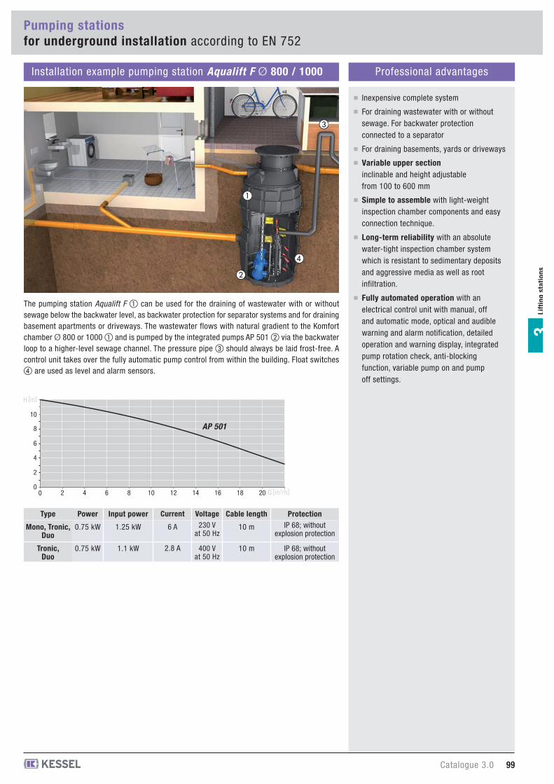
Lif
tin
gsta
tio
ns
3
Installation example pumping station Aqualift F Ø 800 / 1000 Professional advantages
0
4
2
0
6
8
10
102 4 6 8 12 14 16 18 20 Q [m3/h]
H [m]
Inexpensive complete system
For draining wastewater with or withoutsewage. For backwater protectionconnected to a separator
Power
0.75 kW
0.75 kW
Type
Mono, Tronic, Duo
Tronic, Duo
Input power
1.25 kW
1.1 kW
Current
6 A
2.8 A
Cable length
10 m
10 m
ProtectionIP 68; without
explosion protection
IP 68; without explosion protection
Voltage230 V
at 50 Hz
400 Vat 50 Hz
AP 501
For draining basements, yards or driveways
Variable upper sectioninclinable and height adjustablefrom 100 to 600 mm
Simple to assemble with light-weightinspection chamber components and easyconnection technique.
Long-term reliability with an absolutewater-tight inspection chamber systemwhich is resistant to sedimentary depositsand aggressive media as well as rootinfiltration.
Fully automated operation with anelectrical control unit with manual, offand automatic mode, optical and audiblewarning and alarm notification, detailedoperation and warning display, integratedpump rotation check, anti-blockingfunction, variable pump on and pumpoff settings.
The pumping station Aqualift F � can be used for the draining of wastewater with or withoutsewage below the backwater level, as backwater protection for separator systems and for drainingbasement apartments or driveways. The wastewater flows with natural gradient to the Komfortchamber Ø 800 or 1000 � and is pumped by the integrated pumps AP 501 � via the backwaterloop to a higher-level sewage channel. The pressure pipe � should always be laid frost-free. Acontrol unit takes over the fully automatic pump control from within the building. Float switches� are used as level and alarm sensors.
�
�
�
�
Pumping stationsfor underground installation according to EN 752
Catalogue 3.0 99
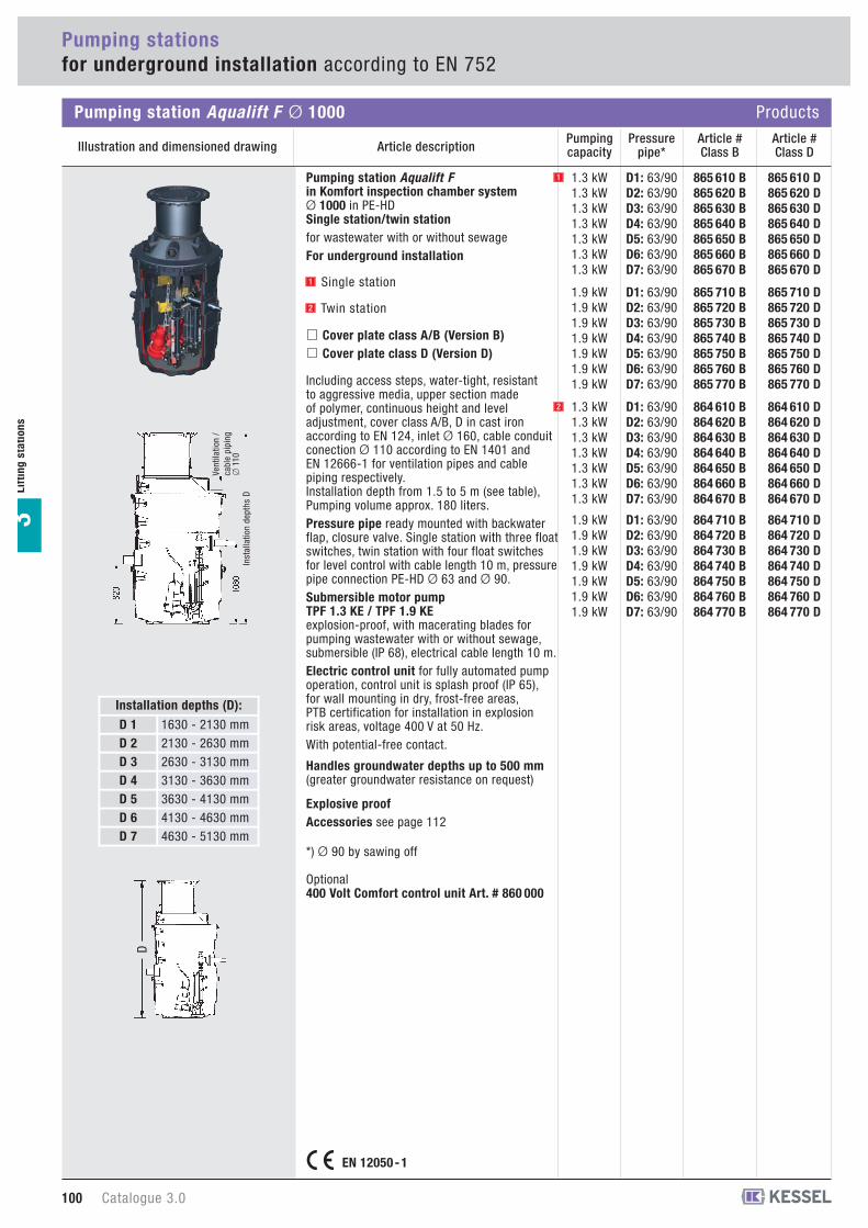
Pumping stationsfor underground installation according to EN 752
Lif
tin
g s
tati
on
s3
865 610 D865 620 D865 630 D865 640 D865 650 D865 660 D865 670 D
865 710 D865 720 D865 730 D865 740 D865 750 D865 760 D865 770 D
864 610 D864 620 D864 630 D864 640 D864 650 D864 660 D864 670 D
864 710 D864 720 D864 730 D864 740 D864 750 D864 760 D864 770 D
865 610 B865 620 B865 630 B865 640 B865 650 B865 660 B865 670 B
865 710 B865 720 B865 730 B865 740 B865 750 B865 760 B865 770 B
864 610 B864 620 B864 630 B864 640 B864 650 B864 660 B864 670 B
864 710 B864 720 B864 730 B864 740 B864 750 B864 760 B864 770 B
D1: 63/90D2: 63/90D3: 63/90D4: 63/90D5: 63/90D6: 63/90D7: 63/90
D1: 63/90D2: 63/90D3: 63/90D4: 63/90D5: 63/90D6: 63/90D7: 63/90
D1: 63/90D2: 63/90D3: 63/90D4: 63/90D5: 63/90D6: 63/90D7: 63/90
D1: 63/90D2: 63/90D3: 63/90D4: 63/90D5: 63/90D6: 63/90D7: 63/90
Pumping station Aqualift Fin Komfort inspection chamber system Ø 1000 in PE-HDSingle station/twin stationfor wastewater with or without sewageFor underground installation
Single station
Twin station
Cover plate class A/B (Version B)Cover plate class D (Version D)
Including access steps, water-tight, resistantto aggressive media, upper section madeof polymer, continuous height and level adjustment, cover class A/B, D in cast ironaccording to EN 124, inlet Ø 160, cable conduitconection Ø 110 according to EN 1401 andEN 12666-1 for ventilation pipes and cablepiping respectively. Installation depth from 1.5 to 5 m (see table), Pumping volume approx. 180 liters.Pressure pipe ready mounted with backwaterflap, closure valve. Single station with three floatswitches, twin station with four float switchesfor level control with cable length 10 m, pressurepipe connection PE-HD Ø 63 and Ø 90.Submersible motor pump TPF 1.3 KE / TPF 1.9 KEexplosion-proof, with macerating blades forpumping wastewater with or without sewage,submersible (IP 68), electrical cable length 10 m.Electric control unit for fully automated pumpoperation, control unit is splash proof (IP 65),for wall mounting in dry, frost-free areas,PTB certification for installation in explosionrisk areas, voltage 400 V at 50 Hz. With potential-free contact.
Handles groundwater depths up to 500 mm(greater groundwater resistance on request)
Explosive proofAccessories see page 112
*) Ø 90 by sawing off
Optional 400 Volt Comfort control unit Art. # 860 000
Pumping station Aqualift F Ø 1000 Products
Illustration and dimensioned drawing Article descriptionArticle #Class D
Article #Class B
Pressurepipe*
Pumping capacity
1.3 kW1.3 kW1.3 kW1.3 kW1.3 kW1.3 kW1.3 kW
1.9 kW1.9 kW1.9 kW1.9 kW1.9 kW1.9 kW1.9 kW
1.3 kW1.3 kW1.3 kW1.3 kW1.3 kW1.3 kW1.3 kW
1.9 kW1.9 kW1.9 kW1.9 kW1.9 kW1.9 kW1.9 kW
1
2
Vent
ilatio
n /
cabl
e pi
ping
�11
0In
stal
latio
n de
pths
D
1
2
D 1D 2D 3D 4D 5D 6D 7
Installation depths (D):1630 - 2130 mm2130 - 2630 mm2630 - 3130 mm3130 - 3630 mm3630 - 4130 mm4130 - 4630 mm4630 - 5130 mm
D
EN 12050 - 1
100 Catalogue 3.0
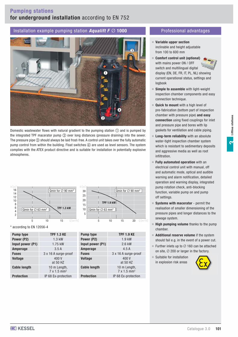
Lif
tin
gsta
tio
ns
3
Installation example pumping station Aqualift F Ø 1000 Professional advantages
Comfort control unit (optional)with mains power ON / OFFswitch and multilingual digitaldisplay (EN, DE, FR, IT, PL, NL) showingcurrent operational status, settings andlogbook
2468
10121416
5 10 15
TPF 1.3 kW
H [m]
Q [m3/h]
Qmin for Ø 90 mm*
Qmin for Ø 63 mm*5
10
15
20
25
30
5 10 15 20
TPF 1.9 kW
Q [m3/h]
H [m]
Qmin for Ø 90 mm*
Qmin for Ø 63 mm*
* according to EN 12056-4
Variable upper sectioninclinable and height adjustablefrom 100 to 600 mm
Simple to assemble with light-weightinspection chamber components and easyconnection technique.
Quick to mount with a high level ofpre-fabrication (bottom part of inspectionchamber with pressure pipe) and easyconnection using fixed couplings for inletand pressure pipe and bores with lipgaskets for ventilation and cable piping.
Long-term reliability with an absolutewater-tight inspection chamber systemwhich is resistant to sedimentary depositsand aggressive media as well as rootinfiltration.
Fully automated operation with anelectrical control unit with manual, offand automatic mode, optical and audiblewarning and alarm notification, detailedoperation and warning display, integratedpump rotation check, anti-blockingfunction, variable pump on and pumpoff settings.
Systems with macerator - permit therealisation of smaller dimensioning of thepressure pipes and longer distances to thesewage system.
High pumping volume thanks to the pumpchamber.
Additional reserve volume if the systemshould fail e.g. in the event of a power cut.
Further inlets up to Ø 160 can be attachedon site, Ø 200 or larger in the factory.
Suitable for installationin explosion risk areas
TPF 1.3 KE1.3 kW
1.75 kW3.5 A
3 x 16 A surge-proof400 V
at 50 HZ10 m Length,7 x 1.5 mm2
IP 68 Ex-protection
Pump typePower (P2) Input power (P1) AmperageFusesVoltage
Cable length
Protection
TPF 1.9 KE1.9 kW2.6 kW4.5 A
3 x 16 A surge-proof400 V
at 50 HZ10 m Length,7 x 1.5 mm2
IP 68 Ex-protection
Pump typePower (P2) Input power (P1) AmperageFusesVoltage
Cable length
Protection
Domestic wastewater flows with natural gradient to the pumping station � and is pumped bythe integrated TPF macerator pump � over long distances (pressure draining) into the sewer.The pressure pipe � should always be laid frost-free. A control unit takes over the fully automaticpump control from within the building. Float switches � are used as level sensors. The systemcomplies with the ATEX product directive and is suitable for installation in potentially explosiveatmospheres.
�
�
�
�
Pumping stationsfor underground installation according to EN 752
Catalogue 3.0 101

Pumping stations for underground installation according to EN 752
Lif
tin
g s
tati
on
s3
825 810 B825 820 B825 830 B
827 810 B827 820 B827 830 B
825 811 B825 821 B825 831 B
827 811 B827 821 B827 831 B
824 811 B824 821 B824 831 B
826 811 B826 821 B826 831 B
825 810 D825 820 D825 830 D
827 810 D827 820 D827 830 D
825 811 D825 821 D825 831 D
827 811 D827 821 D827 831 D
824 811 D824 821 D824 831 D
826 811 D826 821 D826 831 D
D1: KTP 500D2: KTP 500D3: KTP 500
D1: GTF 1000D2: GTF 1000D3: GTF 1000
D1: KTP 500D2: KTP 500D3: KTP 500
D1: GTF 1000D2: GTF 1000D3: GTF 1000
D1: KTP 500D2: KTP 500D3: KTP 500
D1: GTF 1000D2: GTF 1000D3: GTF 1000
Pumping station Aqualift S in inspection chamber system Ø 600 in PE-LLDSingle station/twin stationfor wastewater without sewage / rainwaterFor underground installation
KTP 500 / GTF 1000 float switch controlledremovable pump for conductive ornon-conductive fluids.Input power (P1): 0.48 /1.18 kW.
KTP 500 / GTF 1000 Tronic with removable,pressure sensor controlled pump for conductiveor non-conductive fluids, with SDS controlunit. Input power (P1): 0.48 /1.18 kW.
KTP 500 / GTF 1000 Duo with removable,pressure sensor controlled twin pumps forconductive or non-conductive fluids, with SDScontrol unit. Input power (P1): 2 x 0.48 /1.18 kW.
Cover plate class A/B (Version B)Cover plate class D (Version D)
Inspection chamber system Ø 600 in PE-LLD,resistant to aggressive media, upper section made of polymer, vertically adjustable, cover class A/B, Din cast iron according to EN 124. Groundwater resistant.Inlet Ø 110 (KTP 500 ), Ø 160 (GTF 1000 ),connection for pipe seal for Ø 110 according toEN 1401 and EN 12666-1 - each for ventilationor cable pipe,Note: Consider frost free depth of pressure pipePressure pipe Ø 40 mm outside diameter for PVCglue connection, with integrated non-return flap, 10 mm max solid size, Current: 230 V ~ 50 Hz. Power cable length: 10 m.
Handles groundwater depths up to 2000 mm
Pumping station Aqualift S Ø 600 Products
Illustration and dimensioned drawing Article description
EN 12050 - 2
1
2
3
Article #Class D
Article #Class B
PumpKTP / GTF
1
2
3
Ø860
700
/ 120
0 / 1
700
400
Inst
alla
tion
dept
hs D
D 1D 2D 3
Installation depths (D):800 - 1250 mm
1300 - 1750 mm1800 - 2250 mm
102 Catalogue 3.0
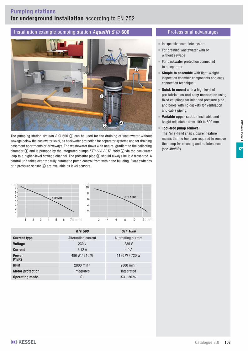
Inexpensive complete system
For draining wastewater with orwithout sewage
For backwater protection connectedto a separator
Simple to assemble with light-weightinspection chamber components and easyconnection technique.
Quick to mount with a high level ofpre-fabrication and easy connection usingfixed couplings for inlet and pressure pipeand bores with lip gaskets for ventilationand cable piping.
Variable upper section inclinable andheight adjustable from 100 to 600 mm.
Lif
tin
gsta
tio
ns
3
Installation example pumping station Aqualift S Ø 600 Professional advantages
12345
76
1 2 3 4 5 6 7
KTP 500
H [m]
Q [m3/h]
2
4
6
8
10
2 4 6 8 10 12
GTF 1000
H [m]
Q [m3/h]
Alternating current
230 V
2.12 A
480 W / 310 W
2800 min-1
integrated
S1
Alternating current
230 V
4.9 A
1180 W / 720 W
2800 min-1
integrated
S3 - 30 %
Current type
Voltage
Current
Power P1/P2
RPM
Motor protection
Operating mode
KTP 500 GTF 1000
The pumping station Aqualift S Ø 600 � can be used for the draining of wastewater withoutsewage below the backwater level, as backwater protection for separator systems and for drainingbasement apartments or driveways. The wastewater flows with natural gradient to the collectingchamber � and is pumped by the integrated pumps KTP 500 / GTF 1000 � via the backwaterloop to a higher-level sewage channel. The pressure pipe � should always be laid frost-free. Acontrol unit takes over the fully automatic pump control from within the building. Float switchesor a pressure sensor � are available as level sensors.
�
�
�
�Tool-free pump removalThe “one-hand snap closure” featuremeans that no tools are required to removethe pump for cleaning and maintenance.(see Minilift )
Pumping stations for underground installation according to EN 752
Catalogue 3.0 103
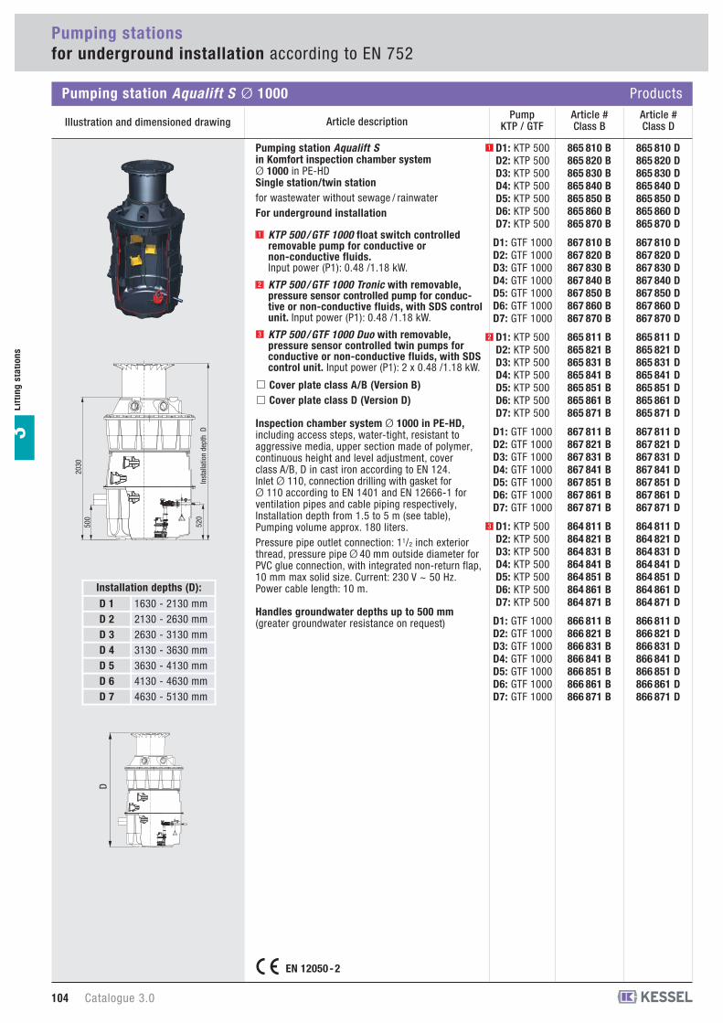
Article descriptionArticle #Class D
Article #Class B
PumpKTP / GTF
Pumping stations for underground installation according to EN 752
Pumping station Aqualift S Ø 1000 Products
Illustration and dimensioned drawing
Lif
tin
g s
tati
on
s3
865 810 B865 820 B865 830 B865 840 B865 850 B865 860 B865 870 B
867 810 B867 820 B867 830 B867 840 B867 850 B867 860 B867 870 B
865 811 B865 821 B865 831 B865 841 B865 851 B865 861 B865 871 B
867 811 B867 821 B867 831 B867 841 B867 851 B867 861 B867 871 B
864 811 B864 821 B864 831 B864 841 B864 851 B864 861 B864 871 B
866 811 B866 821 B866 831 B866 841 B866 851 B866 861 B866 871 B
865 810 D865 820 D865 830 D865 840 D865 850 D865 860 D865 870 D
867 810 D867 820 D867 830 D867 840 D867 850 D867 860 D867 870 D
865 811 D865 821 D865 831 D865 841 D865 851 D865 861 D865 871 D
867 811 D867 821 D867 831 D867 841 D867 851 D867 861 D867 871 D
864 811 D864 821 D864 831 D864 841 D864 851 D864 861 D864 871 D
866 811 D866 821 D866 831 D866 841 D866 851 D866 861 D866 871 D
D1: KTP 500D2: KTP 500D3: KTP 500D4: KTP 500D5: KTP 500D6: KTP 500D7: KTP 500
D1: GTF 1000D2: GTF 1000D3: GTF 1000D4: GTF 1000D5: GTF 1000D6: GTF 1000D7: GTF 1000
D1: KTP 500D2: KTP 500D3: KTP 500D4: KTP 500D5: KTP 500D6: KTP 500D7: KTP 500
D1: GTF 1000D2: GTF 1000D3: GTF 1000D4: GTF 1000D5: GTF 1000D6: GTF 1000D7: GTF 1000
D1: KTP 500D2: KTP 500D3: KTP 500D4: KTP 500D5: KTP 500D6: KTP 500D7: KTP 500
D1: GTF 1000D2: GTF 1000D3: GTF 1000D4: GTF 1000D5: GTF 1000D6: GTF 1000D7: GTF 1000
Pumping station Aqualift S in Komfort inspection chamber system Ø 1000 in PE-HDSingle station/twin stationfor wastewater without sewage / rainwaterFor underground installation
KTP 500 / GTF 1000 float switch controlledremovable pump for conductive ornon-conductive fluids.Input power (P1): 0.48 /1.18 kW.
KTP 500 / GTF 1000 Tronic with removable,pressure sensor controlled pump for conduc-tive or non-conductive fluids, with SDS controlunit. Input power (P1): 0.48 /1.18 kW.
KTP 500 / GTF 1000 Duo with removable,pressure sensor controlled twin pumps forconductive or non-conductive fluids, with SDScontrol unit. Input power (P1): 2 x 0.48 /1.18 kW.
Cover plate class A/B (Version B)Cover plate class D (Version D)
Inspection chamber system Ø 1000 in PE-HD, including access steps, water-tight, resistant toaggressive media, upper section made of polymer,continuous height and level adjustment, coverclass A/B, D in cast iron according to EN 124. Inlet Ø 110, connection drilling with gasket forØ 110 according to EN 1401 and EN 12666-1 forventilation pipes and cable piping respectively, Installation depth from 1.5 to 5 m (see table), Pumping volume approx. 180 liters.Pressure pipe outlet connection: 11/2 inch exteriorthread, pressure pipe Ø 40 mm outside diameter forPVC glue connection, with integrated non-return flap,10 mm max solid size. Current: 230 V ~ 50 Hz.Power cable length: 10 m.
Handles groundwater depths up to 500 mm(greater groundwater resistance on request)
1
2
3
1
2
3
D 1D 2D 3D 4D 5D 6D 7
Installation depths (D):1630 - 2130 mm2130 - 2630 mm2630 - 3130 mm3130 - 3630 mm3630 - 4130 mm4130 - 4630 mm4630 - 5130 mm
520
2030
500
Inst
alla
tion
dept
h D
D
EN 12050 - 2
104 Catalogue 3.0
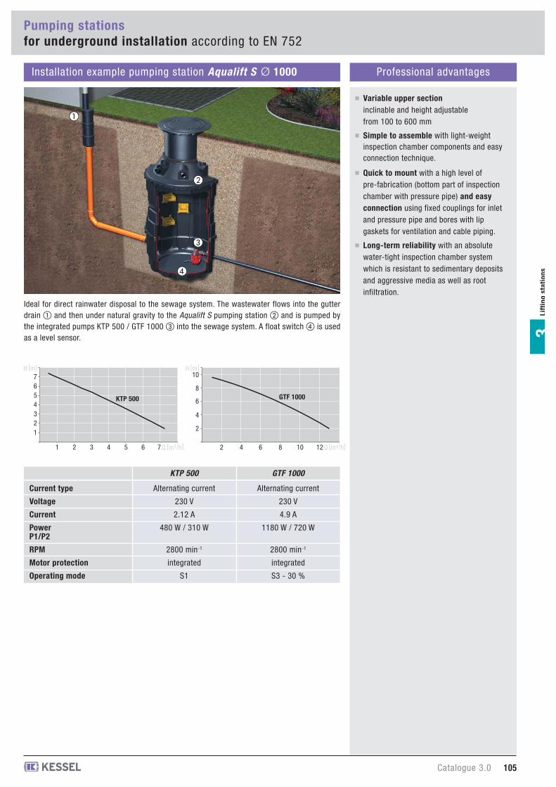
Lif
tin
gsta
tio
ns
3
Installation example pumping station Aqualift S Ø 1000 Professional advantages
Variable upper sectioninclinable and height adjustablefrom 100 to 600 mm
Simple to assemble with light-weightinspection chamber components and easyconnection technique.
Quick to mount with a high level ofpre-fabrication (bottom part of inspectionchamber with pressure pipe) and easyconnection using fixed couplings for inletand pressure pipe and bores with lipgaskets for ventilation and cable piping.
Long-term reliability with an absolutewater-tight inspection chamber systemwhich is resistant to sedimentary depositsand aggressive media as well as rootinfiltration.
12345
76
1 2 3 4 5 6 7
KTP 500
H [m]
Q [m3/h]
2
4
6
8
10
2 4 6 8 10 12
GTF 1000
H [m]
Q [m3/h]
Alternating current
230 V
2.12 A
480 W / 310 W
2800 min-1
integrated
S1
Alternating current
230 V
4.9 A
1180 W / 720 W
2800 min-1
integrated
S3 - 30 %
Current type
Voltage
Current
Power P1/P2
RPM
Motor protection
Operating mode
KTP 500 GTF 1000
Ideal for direct rainwater disposal to the sewage system. The wastewater flows into the gutterdrain � and then under natural gravity to the Aqualift S pumping station � and is pumped bythe integrated pumps KTP 500 / GTF 1000 � into the sewage system. A float switch � is usedas a level sensor.
�
�
�
�
Pumping stations for underground installation according to EN 752
Catalogue 3.0 105

2
4
6
8
10
2 4 6 8 10 12
H [m]
Q [m3/h]
Pressure connection Article #
Submersible pump KTP 500 / KTP 500 TITANfor wastewater without sewagewith/without float switchConnection to pressure pipe 11/4 inch.Outlet side / vertical, cable length 10 m
without float switch
with float switch
Voltage: 230 V ~ 50 HzInput power (P1): 480 WMax. pumping height: 8 mMax. pumping capacity: 8 m3/hMax. submersible depth: 10 mMax. particle size: 10 mmPressure connection: 11/4 inch side / vertical
Special model with titanium shaftSuitable for mechanical and chemical pollutedmedia. Also resistant to chloride-containing media.Not to be used for nitro- and trichloroethylene
KTP 500
guaranteed with
tested quality
Type-testedand monitored
LGA
28 710
28 810
11/4 inch
11/4 inch
28 750
28 850
11/4 inch
11/4 inch
1
2
KTP 500 Products
Illustration and dimensioned drawing Article description
Submersible pumps for wastewater without sewage
Lif
tin
g s
tati
on
s3
Pressure connection Article #
Submersible pump GTF 1000for wastewater without sewagewith/without float switch Connection to pressure pipe 11/4 inch.Outlet side / vertical, without macerator,cable length 10 m
without float switch
with float switch
Voltage: 230 V ~ 50 HzInput power (P1): 1080 WMax. pumping height: 10 mMax. pumping capacity: 11,5 m3/hMax. submersible depth: 10 mMax. particle size: 10 mmPressure connection: 11/4 inch side / vertical
guaranteed with
tested quality
Type-testedand monitored
LGA
281
197
28 760
28 860
11/4 inch
11/4 inch
1
2
GTF 1000 Products
Illustration and dimensioned drawing Article description
1
2
1
2
1
2
KTP 500 TITAN
Alternating current
230 V
4.9 A
1080 W / 620 W
2800 min-1
integrated
S3 - 30 %
Current type
Voltage
Current
Power P1/P2
RPM
Motor protection
Operating mode
GTF 1000
Alternating current
230 V
2.12 A
480 W / 320 W
2800 min-1
integrated
S1
Current type
Voltage
Current
Power P1/P2
RPM
Motor protection
Operating mode
KTP 500
12345
76
1 2 3 4 5 6 7
[m]
Q [m3/h]
106 Catalogue 3.0

Submersible pump KTP 300 (300 W)for wastewater without sewagewith/without float switchWith backwater flap, pivotable connection,cable length 10 m
without float switch
with float switch
Input power (P1): 280 W.Voltage: 230 V ~ 50 Hz.Max. pumping height: 6 m.Max. pumping capacity: 8 m3/h.Max. submersible depth: 10 m.max. particle size: 10 mm.Pressure connection: 1 inch side / verticalRemovable input basket - reduction in the waterlevel to 8 mm possible.
guaranteed with
tested quality
Type-testedand monitored
LGA
28 740
28 840
1 inch
1 inch
1
2
Pressure connection Article #
KTP 300 Products
Illustration and dimensioned drawing Article description
Submersible pumps for wastewater with/without sewage
Lif
tin
gsta
tio
ns
3
1
2
Pressure connection Article #
Submersible pump SPZ 1000 for wastewater containing raw sewagewith/without float switchwith macerator.Connection to pressure pipe 11/4 inch.Outlet side / vertical, cable length 10 m
without float switch
with float switch
Voltage: 230 V ~ 50 HzInput power (P1): 1080 WMax. pumping height: 10 mMax. pumping capacity: 12 m3/hMax. submersible depth: 10 mMax. particle size: 10 mmPressure connection: 11/4 inch side / vertical
28 778
28 779
11/4 inch
11/4 inch
1
2
SPZ 1000 Products
Illustration and dimensioned drawing Article description
1
2
1
2
3
4
5
1 2 3 4 5 6 Q [m3/h]
H [m]
294
258
Alternating current
230 V
1.9 A
280 W / 114 W
2800 min-1
integrated
Schuko
Current type
Voltage
Current
Power P1/P2
RPM
Motor protection
Plug
KTP 300
123456789
2 4 6 8 10 Q [m3/h]
H [m]Alternating current
230 V
4.9 A
1080 W / 620 W
2800 min-1
integrated
S3 - 30 %
Current type
Voltage
Current
Power P1/P2
RPM
Motor protection
Operating mode
SPZ 1000
Catalogue 3.0 107

108 Catalogue 3.0
KESSEL-Product informationWarning and control units
Lif
tin
g s
tati
on
s3
The warning and control units can be used for a widerange of purposes e.g. as warning devices inhousehold and industrial systems as well as forconnection to a remote signal sensor. The warning and control units with potential-freecontact can be connected to the building managementsystem (BMS). The electronic sensors react to allconductive fluids and the optical sensors to allconductive and non-conductive fluids.
READY FOR CONNECTION230 Volt control unit ready for connection by coded connectors(Fig. 1) for pumps and pressure sensor - no need for a qualifiedelectrician for connection.
MENU NAVIGATIONUser-friendly menu navigation in six languages with multi-lingualdisplay (Fig. 2).
INTEGRATED SELF-DIAGNOSIS-SYSTEMWith integrated Self-Diagnosis-System and battery bufferingcontinually monitors all electronic functions.
OPERATIONAL PARAMETERSOperational parameters can easily be custom set by operator -Control unit also for use with pumps from other manufacturers.
ELECTRONIC LOG-BOOKElectronic log-book function past history of pump operation isshown on digital control unit display.
Comfort control units
1 2
Comfort control unitswith mult i- l ine display
230 Volt 400 Volt
Warning andcontrol units for versatile uses
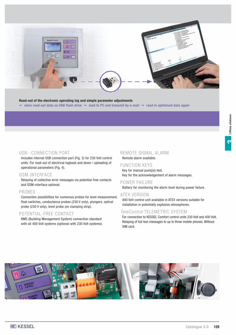
Catalogue 3.0 109
Lif
tin
gsta
tio
ns
3
USB--CONNECTION PORT Includes internal USB connection port (Fig. 3) for 230 Volt controlunits. For read-out of electrical logbook and down / uploading ofoperational parameters (Fig. 4).
GSM-INTERFACERelaying of collective error messages via potential-free contactsand GSM-interface optional.
PROBESConnection possibilities for numerous probes for level measurement,float switches, conductance probes (230 V only), plungers, opticalprobe (230 V only), level probe (on clamping strip).
POTENTIAL-FREE CONTACTBMS (Building Management System) connection standardwith all 400 Volt systems (optional with 230 Volt systems).
REMOTE SIGNAL ALARMRemote alarm available.
FUNCTION KEYSKey for manual pump(s) test.Key for the acknowledgement of alarm messages.
POWER FAILUREBattery for monitoring the alarm level during power failure.
ATEX VERSION400 Volt control unit available in ATEX versions suitable forinstallation in potentially explosive atmospheres.
TeleControl TELEMETRIC SYSTEMFor connection to KESSEL Comfort control units 230 Volt and 400 Volt.Relaying of full text messages to up to three mobile phones. WithoutSIM card.
3
Read-out of the electronic operating log and simple parameter adjustments∞ store read-out data on USB flash drive ∞ load to PC and transmit by e-mail ∞ read in optimised data again
4
28 731 D 28 746 D
28 731 DS 28 746 DS
28 731 DO 28 746 DO
230 V Comfort control units
Mono-/Duo control unit
extremely versatile sensor system for measuring the levelof wastewater with and without sewage. Including plunger for pneumatic level measurement.For greasy wastewater or wastewater at higher temperature onlyin connection with a small compressor for bubble formation(Art. # 28 048)
with pressure sensor*/without extra alarm probe10 m pressure hose (can be extended to 15 m)
with pressure sensor*/conductance probewith separate conductance probe for alarm level measurement10 m pressure hose (can be extended to 15 m)5 m cable (cannot be extended)
with pressure sensor*/float switchwith separate float switch for alarm level measurement10 m pressure hose (can be extended to 15 m, up to 30 m on request)10 m float switch cable (can be extended to 30 m)
with pressure sensor*/optical probewith separate optical probe for alarm level measurement and failuredetection of the optical probe via the control unit 10 m pressure hose(can be extended to 15, up to 30 m on request) 5 m cable for opticalprobe (can be extended to 30 m)
Mono-/Duo control unit
sensor system for level measurementfor wastewater without sewage.With float switches to measure ON 1, ON 2 (only 28 746-S)and OFF levels.
with float switch/without extra alarm probe10 m float switch cable (can be extended to 30 m)
with float switch*/float switchwith separate float switch for alarm level measurement10 m float switch cable (can be extended to 30 m)
*with compressor for air bubbling
1
2
3
4
5
6
28 731 S 28 746 S
28 731 SX 28 746 SX
2
3
4
5
6
1
Warning and control units
230 V Comfort control unit Products
Illustration Article descriptionArticle #
MonoArticle #
Duo
Lif
tin
g s
tati
on
s3
1
3
28 731 DL 28 746 DL2
4
5
6
110 Catalogue 3.0
Article descriptionArticle #
MonoArticle #
Duo
---
28 75728 75828 783
--
28 76228 763
28 75528 75628 781
---
28 75928 761
--
400 V Comfort control unit
suitable for max. switching current from - to2.5 - 4.0 A Mono4.0 - 6.3 A Mono6.3 - 10.0 A Mono
2 x 2.5 - 4.0 A Duo2 x 4.0 - 6.3 A Duo2 x 6.3 - 10.0 A Duo
2.5 - 4.0 A ATEX version, Mono4.0 - 6.3 A ATEX version, Mono
2 x 2.5 - 4.0 A ATEX version, Duo2 x 4.0 - 6.3 A ATEX version, Duo
28 731 P 28 746 P
28 731 LL -
230 V Comfort control units
Mono-/Duo control unit
Extremely versatile sensor system for measuring the levelof wastewater with and without sewage.Including level probe for pneumatic level measurement andfailure detection of the level probe via the control unit.For greasy wastewater or wastewater at higher temperature,the use of a small compressor is not necessary.
with level probe/without extra alarm probe10 m level probe cable (can be extended to 30 m)
with level probe/float switchwith float switch for alarm level measurement10 m level probe cable (can be extended to 30 m)10 m float switch cable (can be extended to 30 m)
Mono-/Duo control unit
sensor system for level measurementfor wastewater without sewage.Including alarm level measurement. Not suitable for rainwateror non-diluted condensate. Including conductance probes for themeasuring of ON 1, ON 2 (28 746-LLF/28746-LLV only), OFF andALARM level. Switching points cannot be adjusted freely.
Mono control unit
with conductance probe/conductance probeLevel ON/OFF fixed, alarm level can be adjusted5 m cable for conductance probe
Duo control units
with conductance probe/conductance probeON 1 fixed/ON 2 variable/ALARM with fixed distance to ON 25 m cable for conductance probe
with conductance probe/conductance probeON 1 variable/ON 2 fixed/ALARM with fixed distance to ON 25 m cable for conductance probe)
7
8
9
10
11
- 28 746 LLF
- 28 746 LLV
185-043 185-043
185-045 185-045
7
8
9 10 11
Warning and control units
Lif
tin
gsta
tio
ns
3
230 V Comfort control unit Products
Illustration
7
28 731 PS 28 746 PS8
9
10
11
400 V Comfort control unit Products
Illustration Article descriptionArticle #
MonoArticle #
Duo
Float switchfloat switch cable 10 m
float switch cable 20 m
28 082 28 082Level probe
Catalogue 3.0 111
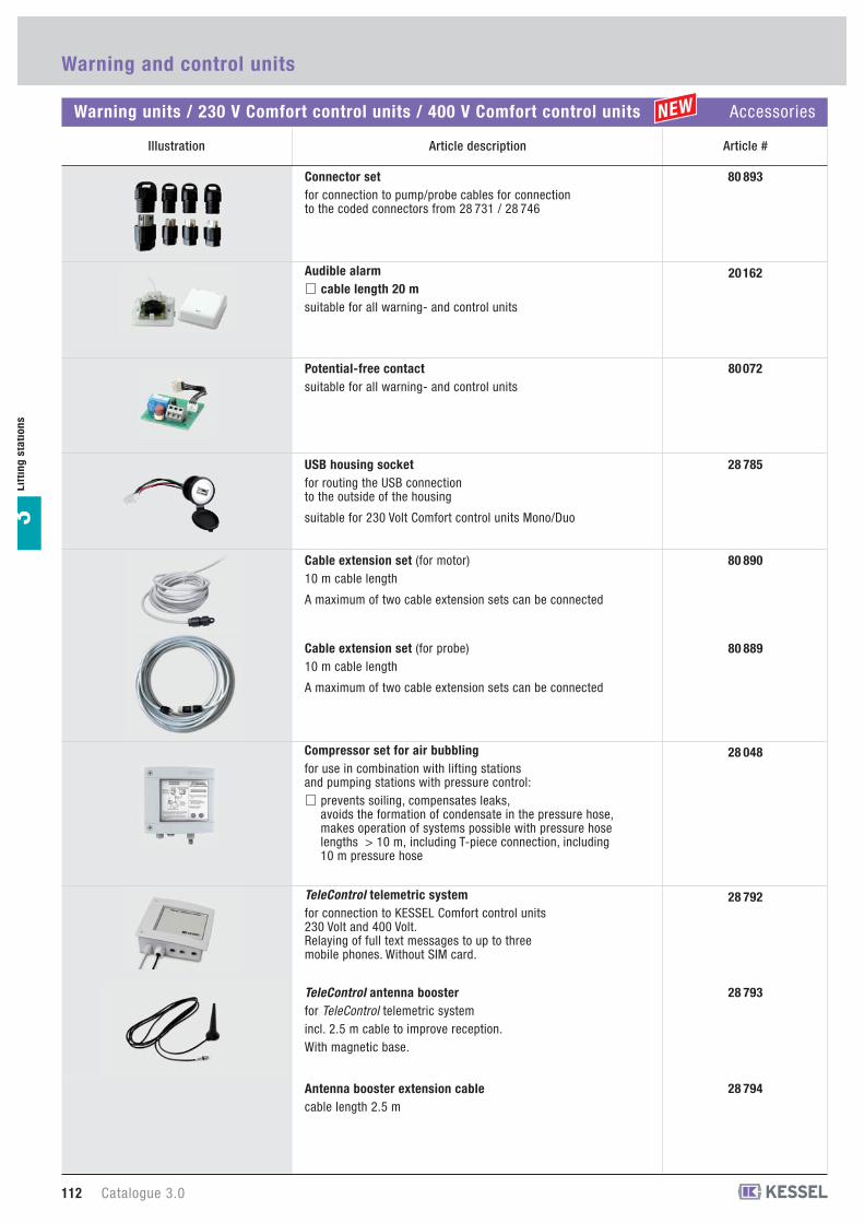
28 794Antenna booster extension cablecable length 2.5 m
28 792TeleControl telemetric systemfor connection to KESSEL Comfort control units230 Volt and 400 Volt. Relaying of full text messages to up to threemobile phones. Without SIM card.
28 793TeleControl antenna boosterfor TeleControl telemetric systemincl. 2.5 m cable to improve reception.With magnetic base.
28 048Compressor set for air bubblingfor use in combination with lifting stationsand pumping stations with pressure control:
prevents soiling, compensates leaks,avoids the formation of condensate in the pressure hose,makes operation of systems possible with pressure hoselengths > 10 m, including T-piece connection, including10 m pressure hose
28 785USB housing socketfor routing the USB connectionto the outside of the housing
suitable for 230 Volt Comfort control units Mono/Duo
80 893Connector setfor connection to pump/probe cables for connectionto the coded connectors from 28 731 / 28 746
20 162Audible alarmcable length 20 m
suitable for all warning- and control units
80 072Potential-free contactsuitable for all warning- and control units
80 889
Cable extension set (for motor)10 m cable length
A maximum of two cable extension sets can be connected
Cable extension set (for probe)10 m cable length
A maximum of two cable extension sets can be connected
80 890
Warning and control units
Warning units / 230 V Comfort control units / 400 V Comfort control units Accessories
Illustration Article description
Lif
tin
g s
tati
on
s3
Article #
112 Catalogue 3.0