waste tyre recycling plant - sants group
TRANSCRIPT

WASTE TYRE RECYCLING PLANT
The whole pyrolysis system is mainly composed by 14 parts, which are reactor,
insulation layer, furnace, transmission device , oil-water separator, depositing tank,
cooling pool, cooling pipes, light oil tank, safety device, water seal, dedusting system,
draft fan, chimney.
The keys of pyrolysis machine are reactor, cooling system, safety system and exhaust
disposal system.
No. Item Content
1 Equipment Model SIT5 SIT8 SIT10 SIT12
2 Raw materials Waste Rubber,
Plastic
Waste Rubber,
Plastic
Waste Rubber,
Plastic
Waste Rubber,
Plastic
3 Structure Horizontal
rotation Horizontal rotation Horizontal rotation Horizontal rotation
4 capacity in 24H
5 tons
8 tons
10 tons
12 tons
5 24-hour production 2.5 tons crude oil 4 tons crude oil 5 tons crude oil 6 tons crude oil

6 Work pressure Atmospheric Atmospheric Atmospheric Atmospheric
7 Host Speed 0.4 Turn / min 0.4 Turn / min 0.4 Turn / min 0.4 Turn / min
8 With force 9-12 KW / hour 9-12 KW / hour 9-12 KW /hour 9-12 KW / hour
9 Cooling Water cooling Water cooling Water cooling Water cooling
10 Cooling water
consumption 0.2(t/h) 0.3(t/h) 0.4(t/h) 0.5(t/h)
11 Weight of whole
plant 19t 21t 25t 32t
12 Heating Directly Directly Directly Directly
13 Installation A base A base A base A base
14 Noise dB(A) ≤85 ≤85 ≤85 ≤85
15 Host size (D× L) 2200×5000 2200 × 6600 2600 × 6600 2800×6600
16 Forms of work Intermittent Intermittent Intermittent Intermittent
Outputs & Applications
The main products: fuel oil, combustible gas, crude carbon black and steels, which are widely used in hotels,
restaurants, bathing centers, power engines, chemical sector and so on.
Equipment features
1. Operate under atmospheric pressure
2. Automatic decompression
3. Automatic sludge discharge
4. Latest high-tech
5. Danger-free
6. Pollution-free
7. Energy-conservation
8. Of great profits
Benefits from the advanced pyrolysis tech:
A. Regaining energy and value from waste in the form of fuel and charcoal
B. Reducing the plastic and tire pollution to land

C. Recycling of plastics and tires which are Eco-friendly
D. Commercially viable process
E. End product oil is used as substitute to Furnace oil
F. Perfect solution for Polymer waste management
G. Raw material (waste tires, waste plastics) available
H. Zero emission process: no harm to environment
I. Less reaction time and more energy savings
J. Plant is Energy self sufficient
Device composition
1.Heating system
Reactor
Using Q245R boiler steel and the thickness is between
14mm and 18mm.(The thickness would be adjusted
according to the requirements of the customers).
The main engine uses horizontal-type of 360ostructure-0.4 r/min
2.Separation system
Gas separator & Depositing tank
Depart the heavy oil and impurities from the oil gas to purify the oil.
3.Condensing system
a. The "S" shape extends the condensing area, up to 42 m2
b. The open pool makes natural cooling viable, which is energy conservation and free of danger
c. Cooling down quickly with the pipeline diameter of 219mm and
length of 6m d. The elbows make it easier and convenient to clean and maintain e. Just need to make up the vaporized water, it's water conservation f. Condensing tower and vertical condensers can be added based
on the customers' requirements Our newest design: set one condenser between water seal and oil tank to cool the waste gas so that the oil yield rate will be higher
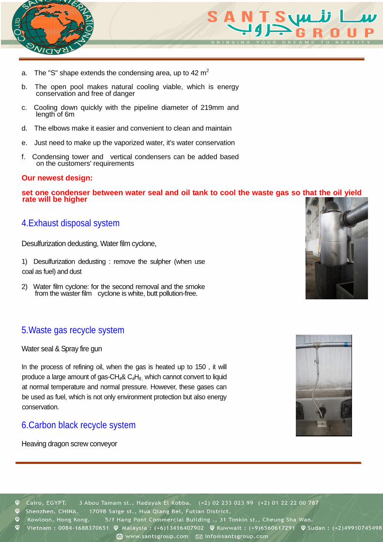
4.Exhaust disposal system
Desulfurization dedusting, Water film cyclone,
1) Desulfurization dedusting : remove the sulpher (when use
coal as fuel) and dust
2) Water film cyclone: for the second removal and the smoke from the waster film cyclone is white, butt pollution-free.
5.Waste gas recycle system
Water seal & Spray fire gun
In the process of refining oil, when the gas is heated up to 150 , it will
produce a large amount of gas-CH4& C4H8 , which cannot convert to liquid
at normal temperature and normal pressure. However, these gases can
be used as fuel, which is not only environment protection but also energy
conservation.
6.Carbon black recycle system
Heaving dragon screw conveyor

The solid residua will be left after the catalyst splitting from scrap plastic, approximately take up 5% to 10% of the waste
tire. Its main component is the black carbon, which can be used as raw materials in industry, as well could be mixed with
the pulverized coal ash to produce the raw material of the thermal power plant, and also could be applied to the
manufacturing of the pulverized coal ash brick (a kind of environmental protection building material).
FLOWCHART

Feed the reactor with raw materials through the feeding door by labor or machine
and then close it tightly. Heat the reactor with coal, wood or other fuels. Some
harmful smoke will come out along with the heating, but it can be removed by the
desulfurization deduster and the water film cyclone. The smoke form the exhaust
disposal system is no different from the air. The draft fan helps to inhale the
smoke from the pipe and then release it into the sky more quickly.

The oil gas will travel from the reactor to the gas separate, in which the heavy
oil and impurities will depart from the gas due to the gravity. Then the gas will
continue its journey into the depositing tank for a second separation. After that ,
the cleaned oil gas will run into the cooling condensing pipes in the cooling pool,
where the gas will convert to liquid, the oil, and then flow into the oil tank for
storage.
There will be some waste gas in the oil tank. It will follow the pipe over the oil
tank into the cooling pool for a second condensing so that the remained oil gas
could turn to oil to improve the oil yield rate. As for the waste gas, that cannot
transform to liquid will go to the water seal and then to the furnace for burning. It
is not only environment protection but also energy conservation.