waste management in electroplating industrygcpcenvis.nic.in/thesis/waste management in...
TRANSCRIPT
1
Waste Management in Electroplating Industry
A Dissertation Report
Submitted in Partial Fulfilment of
the Requirements for the award of
Master of Technology Degree
in
Environmental Science & Technology
2009 – 2011
To
Thapar University
By
Anuj Mathur
Roll No. 600901003
Under the Guidance of
Dr. Nirmala Saraswat Dr. A.S. Reddy
Fellow Associate Professor
Centre for Environmental Studies Department of Biotechnology and Environmental Sciences
TERI, Thapar University
New Delhi – 110020 Patiala, Punjab ______________________________________________________________
Work Done At
The Energy and Resources Institute

2
ACKNOWLEDGEMENT
I express my sincere gratitude to Dr. R. K. Pachauri, Director, The
Energy and Resources Institute (TERI), New Delhi for giving me
permission to pursue the dissertation work and to avail the facilities for
carrying out the work in the prestigious institute.
At the outset, I would like to express our deep sense of gratitude
to our supervisor Dr. Nirmala Saraswat, fellow, TERI, New Delhi and
Dr. M.S Reddy, H.O.D. of Department of Biotechnology And
Environmental Sciences, Thapar University, Patiala, for their keen
interest and permitting us to carry out our project work in this esteemed
Institute.
I sincerely express my deep sense of gratitude and immense respect
to my guide Dr. Nirmala Saraswat, fellow of centre for Environmental
studies, The Energy and Resources Institute (TERI), New Delhi for his
scholarly guidance, generous encouragement and suggestion throughout
the course of my dissertation work.
I am extremely grateful to my guide Dr. Akepati S. Reddy,
Associate Professor, Department of Biotechnology &
Environmental Sciences, Thapar University, Patiala for his keen
interest and encouraging me in one way or other to carry out my
dissertation in TERI, New Delhi.

3
I also express my sincere thanks to my father Shri. Ajit Kumar
Mathur for providing his valuable suggestions and co-operation. My
heartfelt gratitude also reach out to my grandparents, my brother and
mother for their constant support, inspiration and encouragement.
At last but not the least, I express my special thanks to all my
friends for their love and support, without which this task would have
been difficult.
Anuj Mathur
(Environmental Science and
Technology)
Thapar University
Patiala, Punjab

4

5
6
Declaration
I, the undersigned hereby declare that the research work presented
in the M.Tech project entitled “Waste Management in Electroplating
Industry” has been carried out under the guidance of Dr. Nirmala
Saraswat, fellow, TERI, New Delhi. Further, I declare that no part of
this Dissertation has been submitted for a degree or any other
qualification of any other university or examining body in
India/elsewhere.
Anuj Mathur
(Environmental Science and Technology)
Thapar University
Patiala, Punjab
7
TABLE OF CONTENTS PAGE No.
Chapter 1
Introduction………………………………………………………….……..…………… 1
1.1 Introduction
1.2 Rationale
1.3 Organization of thesis
Chapter 2
Literature Review…………………………………………………..……………………. 4
2.1 Brief History and Present Scenario
2.2 Consumption of chemicals in electroplating
2.3 Review of waste Minimization Techniques
2.4 Chemical Recovery techniques
2.4.1 Reverse osmosis (RO)
2.4.2 Adsorption Technique for Chemical Recovery
2.4.3 Ion exchange technique for electroplating
Chapter 3
Basic components of Electroplating Process ……………………..…….………………………..
10
3.1 Components of electroplating process
3.2 Basic principle of Electroplating Process
3.3 Quantitative aspects of Electrolysis
3.3.1 Faraday’s First Law
3.3.2 Practical consideration in Electroplating
3.3.3 Empirical Approach to Calculate Waste of Anode in Copper Plating
3.3.4 The Faraday’s second law
3.4 Optimal Operating Conditions of Electroplating Process
3.4.1 Temperature
3.4.2 Cathode current density
3.4.3 Anodes

8
3.4.4 Power supply
3.4.5 Agitation
3.4.6 Filtration
Chapter 4
Steps for Electroplating process……………………………………………………….. 16
4.1 Main constituents of Electroplating Process
4.2 Surface preparation
4.3 Pre-treatment
4.4 Electro Plating Process of different metals
4.4.1 Chemicals used in electroplating other than electrolytes and anodes
4.4.2 Problems faced in using different electrolytes in electroplating
4.5 Post Plating Treatment
Chapter 5
Minimization of waste…………………………….......................................................
36
5.1 Characterization of Waste generated from Electroplating Industry
5.1.1 Solid waste generated from the process
5.1.2 Liquid wastes
5.1.3 Characterization of Solid and Liquid wastes generated from Electroplating
Industry (by CPCB)
5.1.4 Characterization of Gaseous wastes generated from Electroplating Industry
5.2 Waste Minimization in Electroplating Industry
5.2.1 Minimizing the resource use
5.2.2 Modifying the process
5.2.2.1 The use of sensors
5.2.2.2 Use of suitable plating baths
5.2.3 Modifying the product.
5.3 Minimization of drag–out losses
5.4 Modified Rinsing techniques
9
5.4.1 Counter current rinsing
5.4.1.1 Factors affecting Counter-current rinsing
5.4.1.2 Case study of Counter current rinsing
5.4.1.3 Estimation of cost for 2 stage Counter current rinsing
5.4.1.4 Payback period in counter current rinsing
5.4.1.5 Disadvantages of counter current rinsing
5.4.2 Spray Rinsing Technique
5.4.2.1 Spray Rinsing Case Study
5.4.2.2 Payback period in spray rinsing technique
5.4.2.3 Problems in spray rinsing
Chapter 6
Chemical recovery…………...…………….……………………………………………..
48
6.1 Rationale of Chemical recovery
6.2 Different techniques of Chemical/Metal Recovery
6.2.1 Evaporation method for Chemical recovery
6.2.1.1 Fundamental principle underlying Evaporation process
6.2.1.2 Process of Evaporation using Atmospheric Evaporator
6.2.1.3 Atmospheric Evaporators Case Study
6.2.1.3.1 Estimation of cost for atmospheric evaporator
6.2.1.3.2 Calculating the savings
6.2.1.3.3 Payback period using atmospheric evaporator
6.2.1.4 Disadvantages of Evaporator
6.2.2 Ion-Exchange
6.2.2.1 Principle of Ion exchange process
6.2.2.2 Regeneration of ion exchange resin
6.2.2.3 Process of Ion exchange
6.2.2.4 Ion exchange case study
6.2.2.4.1 Estimation of cost
6.2.2.4.2 Savings in ion exchange
10
6.2.2.4.3 Payback period of Ion exchange
6.2.2.5 Disadvantages of Ion exchange
6.2.3 Reverse osmosis (RO) for recovery of chemicals
6.2.3.1 Factors associated with performance of RO
6.2.3.2 Case study of Reverse Osmosis
6.2.3.2.1 Estimate of cost
6.2.3.2.2 Savings by using Reverse Osmosis
6.2.3.2.3 Payback period of Reverse Osmosis
6.2.3.3 Disadvantages of RO system
6.2.4 Electro Dialysis
6.2.4.1 Principle of electro dialysis
6.2.4.2 Factors affecting Electro dialysis
6.2.4.3 Case study of Electro dialysis
6.2.4.3.1 Cost of Electro dialysis
6.2.4.3.2 Savings by using electro dialysis
6.2.4.3.3 Payback period of Electro dialysis equipment
6.2.4.4 Disadvantages of Electro dialysis
6.3 Overall comparison of chemical recovery techniques
Chapter 7
Summary and Conclusion………………………………………………… 72
References

11
LIST OF FIGURES Page
no.
Figure 2.1 Increasing trend of growth of electroplating Industry in India 4
Figure 3.1 Basic components of Electroplating 11
Figure 4.1 Typical flow chart of Electroplating process 35
Figure 5.1 Cost of components of 2 stage counter current rinsing 42
Figure 5.2 Circular spray rinsing tank 45
Figure 6.1 Process of Reverse Osmosis 60
Figure 6.2 Chemical recovery of nickel from Watt’s plating bath solution by 66
Electro dialysis

12
13
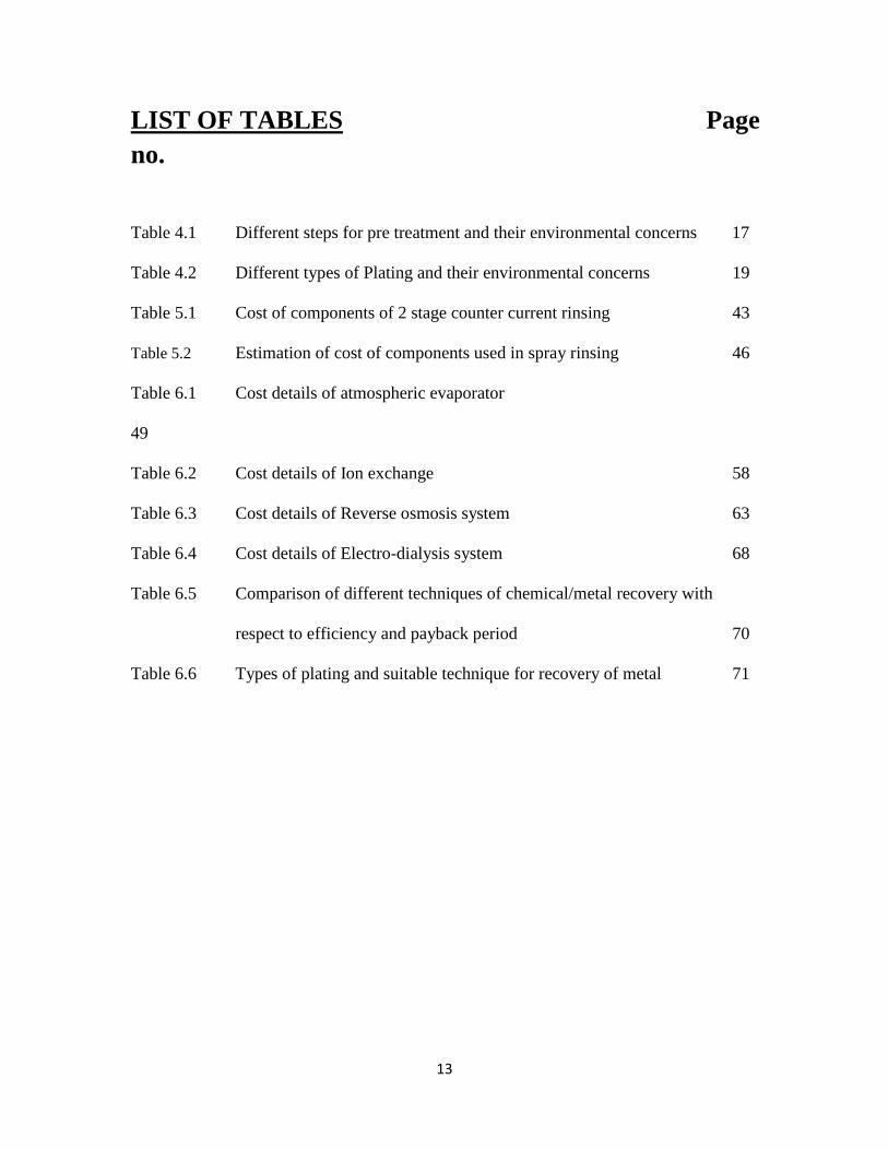
LIST OF TABLES Page
no.
Table 4.1 Different steps for pre treatment and their environmental concerns 17
Table 4.2 Different types of Plating and their environmental concerns 19
Table 5.1 Cost of components of 2 stage counter current rinsing 43
Table 5.2 Estimation of cost of components used in spray rinsing 46
Table 6.1 Cost details of atmospheric evaporator
49
Table 6.2 Cost details of Ion exchange 58
Table 6.3 Cost details of Reverse osmosis system 63
Table 6.4 Cost details of Electro-dialysis system 68
Table 6.5 Comparison of different techniques of chemical/metal recovery with
respect to efficiency and payback period 70
Table 6.6 Types of plating and suitable technique for recovery of metal 71
14
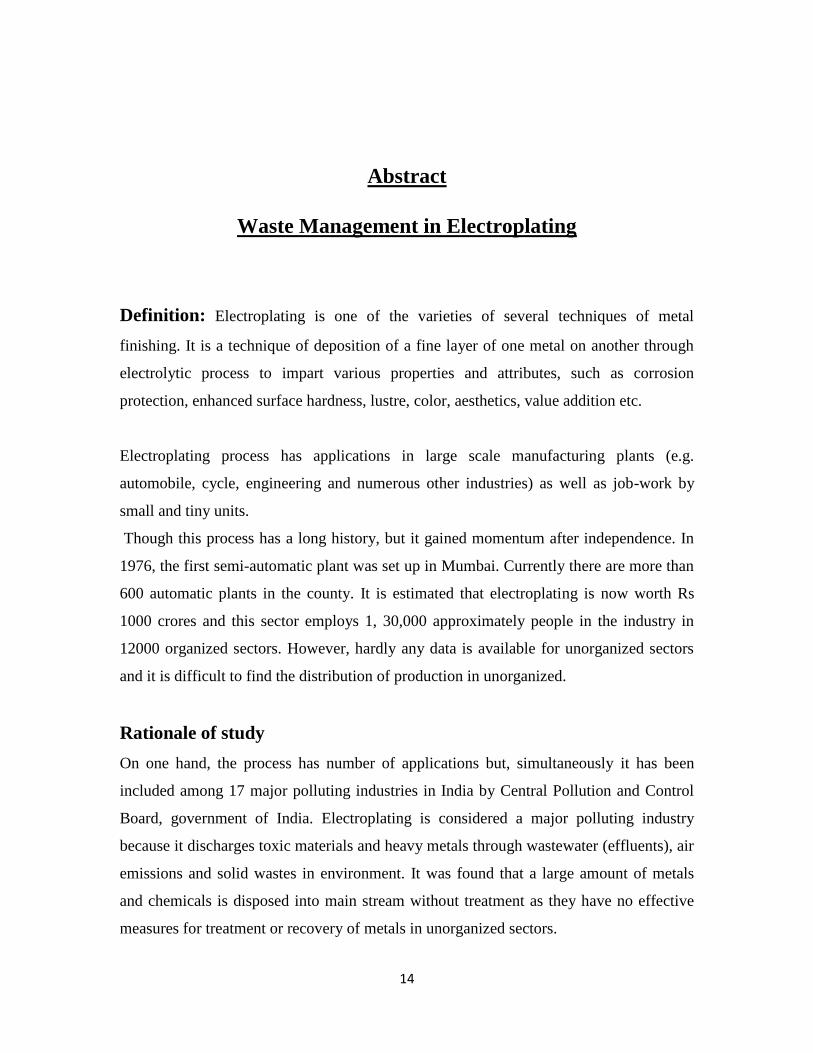
Abstract
Waste Management in Electroplating
Definition: Electroplating is one of the varieties of several techniques of metal
finishing. It is a technique of deposition of a fine layer of one metal on another through
electrolytic process to impart various properties and attributes, such as corrosion
protection, enhanced surface hardness, lustre, color, aesthetics, value addition etc.
Electroplating process has applications in large scale manufacturing plants (e.g.
automobile, cycle, engineering and numerous other industries) as well as job-work by
small and tiny units.
Though this process has a long history, but it gained momentum after independence. In
1976, the first semi-automatic plant was set up in Mumbai. Currently there are more than
600 automatic plants in the county. It is estimated that electroplating is now worth Rs
1000 crores and this sector employs 1, 30,000 approximately people in the industry in
12000 organized sectors. However, hardly any data is available for unorganized sectors
and it is difficult to find the distribution of production in unorganized.
Rationale of study
On one hand, the process has number of applications but, simultaneously it has been
included among 17 major polluting industries in India by Central Pollution and Control
Board, government of India. Electroplating is considered a major polluting industry
because it discharges toxic materials and heavy metals through wastewater (effluents), air
emissions and solid wastes in environment. It was found that a large amount of metals
and chemicals is disposed into main stream without treatment as they have no effective
measures for treatment or recovery of metals in unorganized sectors.

15
At the same time it is to be kept in mind that majority of units are in tiny and small scale,
which are not able to upgrade the technology immediately to achieve cleaner production.
Thus, it is not possible to protect the environment in a significant manner, unless cleaner
production is achieved. Consequently, there is a need to adopt a balanced and practical
approach so that goal is achieved over a period of time.
In view of its immense relevance, there is a need to plan a strategy that should focus on
waste minimization techniques and treatment to control pollution. This is the topic of my
thesis entitled “Waste management in electroplating industry”.
Objectives
For the thesis we will have the following objectives:
(A) Collect detailed information on material used in electroplating (like nickel,
chromium, silver etc):
1) Different solvents used for surface preparation and pre-treatment
2) Quantification of water used in pre-treatment and post treatment.
3) Quantification of Chemicals in Plating
4) Types of techniques in Chemical Recovery
5) Quantification of sludge production
(B) Waste minimization techniques
(C) Recoveries of chemicals from waste rinse water, so that it metals and chemicals
can be re-used.
Study Area
My research work is based on the secondary data collected in the survey done in
organized sectors of Electroplating Industries in Moradabad, located on banks of river
Ramganga, Uttar Pradesh, India. Most of the units operate illegally from the inner city
residential areas.

16
Questionnaires
Data collection was quantitative in nature. Information on classification of industries was
collected. The questionnaire was divided in 6 sections:
a) General information
b) Information on pre-treatment
c) Information on plating
d) Information on post-treatment
e) Information on chemical recovery
f) Waste information.

17
CHAPTER – 1
Introduction
1.1 Introduction
Electroplating is one of the several techniques of metal finishing. It is a technique of
deposition of a fine layer of one metal on another through electrolytic process to impart
various properties and attributes, such as corrosion-protection, enhanced surface
hardness, lustre, colour. They also add to the aesthetic value of object.
Electroplating process has applications in:
a) Large scale manufacturing plants (e.g. automobile, cycle, engineering and
numerous other industries)
b) Job-work by small and tiny units.
They are spread across the entire country with significant concentration in several states
like Punjab, Haryana, Maharashtra, Karnataka, Andhra Pradesh, Tamil Nadu, West
Bengal and in some parts of Uttar Pradesh (UP).
1.2 Rationale
The main concern in Electroplating Industry is to control toxic material discharged by it
that is why it has been included among 17 major polluting industries in India by Central
Pollution Control Board, Government of India. Electroplating is considered a major
polluting industry because it discharges toxic materials and heavy metals through
wastewater (effluents), air emissions and solid wastes in environment.
In order to control pollutants various techniques of treatment of waste are applied. Since,
these techniques are very common in practices and are usually followed. These
techniques for treatment as well as electroplating process require a large quantity of
water, chemicals and equipments which again add the cost of process. Therefore, from
economic point of view, there is a requirement to manage waste in a cost-effective
18
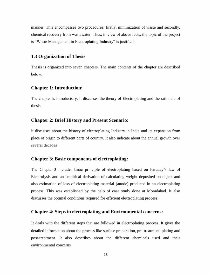
manner. This encompasses two procedures: firstly, minimization of waste and secondly,
chemical recovery from wastewater. Thus, in view of above facts, the topic of the project
is “Waste Management in Electroplating Industry” is justified.
1.3 Organization of Thesis
Thesis is organized into seven chapters. The main contents of the chapter are described
below:
Chapter 1: Introduction:
The chapter is introductory. It discusses the theory of Electroplating and the rationale of
thesis.
Chapter 2: Brief History and Present Scenario:
It discusses about the history of electroplating Industry in India and its expansion from
place of origin to different parts of country. It also indicate about the annual growth over
several decades
Chapter 3: Basic components of electroplating:
The Chapter-3 includes basic principle of electroplating based on Faraday’s law of
Electrolysis and an empirical derivation of calculating weight deposited on object and
also estimation of loss of electroplating material (anode) produced in an electroplating
process. This was established by the help of case study done at Moradabad. It also
discusses the optimal conditions required for efficient electroplating process.
Chapter 4: Steps in electroplating and Environmental concerns:
It deals with the different steps that are followed in electroplating process. It gives the
detailed information about the process like surface preparation, pre-treatment, plating and
post-treatment. It also describes about the different chemicals used and their
environmental concerns.

19
Chapter 5: Waste Minimization Techniques:
This chapter deals with the techniques for minimization of waste generation, by reducing
the quantity of water and resources used and recycling of the electrolyte in plating bath.
Chapter 6: Chemical Recovery:
This chapter analyses the recovery of chemicals and metals from the wastewater and
electrolytes. It also presents the specific techniques used for specified plating. It also
describes the beneficial effects of chemical recovery over the traditional method.
Chapter 7: Summary and Conclusion:
This chapter presents summary and conclusion of project work. Limitation of the work
and scope for further research is also discussed in this chapter.

20

21
CHAPTER - 2
Literature Review
2.1 Brief History & Present Scenario
Electroplating has a long history in India. Like many other industrial activities, it gained
momentum after independence. Modern techniques in electroplating started in early
sixties in India, but the first semi automatic plant was set up in 1976 in Mumbai. Since
then, the industry has grown steadily without facing any recession. Currently there are
more than 600 automatic plants in the country (Comprehensive Industry Document on
Electroplating Industry (COINDS)), 2007)
Although official figures are not available, estimates indicate that in 1970, electroplating
industry was of Rs. 100 million. During the period 1970-85, the government policy on
the restriction import in force led to high growth of this industry (International
Metalworkers Federation, 2002).
The growth of the industries is shown in figure 2.1. Though the curve of the growth rises
steadily from 1980-2002 but a jump was observed in decade 2002-2012. It is estimated
that electroplating industry may now worth Rs. 2000 crores (Rs. 20,000 million) in year
2012.
Figure 2.1 Increasing trend and predictions based on growth rate of electroplating
Industry in India
(Source: Comprehensive Industry Document on Electroplating Industry (COINDS))
22
2.2 Consumption of chemicals in electroplating process
Since, the report mentions (Comprehensive Industry Document on Electroplating
Industry, COINDS) about the organized units but hardly any data is available for
unorganized units. Thus, it is difficult to find out the distribution of production between
the organized and small-scale / tiny / unorganized sector. The official figure quoted in the
report is that about 1, 30,000 people are employed in approximately 12,000 organized
units. However, judging on the basis of the consumption of chemicals and additives, it is
estimated that about 18,000 tons are consumed by organized sector, while tiny and
unorganized sector consumes about 10,000 tons.
(Source: Comprehensive industrial document, CPCB).
2.3 Review of waste minimization techniques
Though this industry is useful from economic point of view but this industry produces
hazardous electroplating waste and is one of the major contributors to heavy metal
pollution in surface waters [Ajmal et al., (1993) and Golomb (1972)]. So there is a need
to control pollutants present in the waste produced by the process of electroplating.
Over a few decades, a variety of methodologies and technologies for waste minimization
have been developed in this industry.
Huang et al.,., (1991) developed a software MIN-CYANIDE, that contained various
solutions and algorithm for waste minimization of cyanide levels produced in
electroplating plants. This software also provided Waste Minimization opportunities
based on the inputs and also recommended high prioritized measures for source reduction
(chemicals). However, the software was restricted to cyanide-containing waste streams
only, and was incapable of providing any decision for the support for the minimization of
many other chemicals, metal and non-metal containing waste streams.
Other scientists, namely, Y.L. Huang and K.Q. Luo (1997) made an intelligent decision
making approach (software called WMEP- advisor) for waste minimization decision
support system. But, the program was based on fuzzy linguistic concepts of LOW,
MEDIUM and HIGH etc which were related to inputs of electroplating process. So, it
23
was not able to quantify precisely the LOW, MEDIUM and HIGH inputs, for e.g.
EXCESSIVE drag out, HIGH temperature etc.
The common flaw in the above techniques was that none of them have been classified
and compared in terms of cost. With the advancement of technology, efforts began for the
recovery of chemicals. Several techniques were developed for recovery of chemicals and
metals which are listed below.
2.4 Chemical Recovery Techniques
2.4.1 Reverse osmosis (RO)
Sato et al.,., (1977) developed a metal plating waste water reclamation system which
consisted of reuse of waste water from pre-treatment and post-treatment process with the
help of RO plant. The waste water discharged from the electro-plating equipment,
contained acidic chromium and alkaline cyanides. However, this study proved to be
unsuccessful because of the fluctuation in the quality of inflowing waste water, which
made the treatment difficult.
Kremen et al., (1977) reported a RO scheme for metal finishing wastewater containing
Cu2+
, Zn2+
, Cr 3+
and Cr 6+
, where, 95% of water recovery was found that could be reused
in process.
Koga and Ushikoshi (1977) used a RO system to recover valuable paints in electro
coating for the surface treatment of aluminum products. It was shown that the plating
solution could be reused after RO treatment as rinse water with recoveries of up to 99%.
Also, it was estimated that the paints recovery process could result in substantial savings
in operating costs.
Kamizawa et al., (1978) studied the treatment of gold plating rinse by RO. They found
that the rejection of gold declined from 92% to 82% because of the multi-ion effect.
But, the RO technique was very costly because of the expensive membrane replacement
periodically. There was a need to initiate less expensive technique for chemical recovery.

24
2.4.2. Adsorption Technique for Chemical Recovery
Srinivasan et al., (1988) used Rice husk as an adsorbent for hexavalent Chromium.
Alaets et al., (1989) used carboneous material obtained from Coconut shell to study the
adsorption of hexavalent chromium.
Pollard et al., (1992) suggested biomass as an absorbent over use of activated carbon for
adsorption, as activated carbon has high cost of recycling which is a drawback for
developing countries.
Sharma and Forster (1993) discovered the sphagnum moss peat to be an effective
adsorbent for hexavalent Chromium. But, the recovery of Chromium was only 50%.
Gupta et al., (2009), Sawalha et al., (2009), Wang et al., (2009), Aydin et al., (2008),
McKay (1995), Bailey et al., (1999) worked on agricultural residues as low-cost
adsorbents for heavy metals in wastewater. They received great attention by developing
countries.
Srivastava et al., used waste slurry from fertilizer plants as an adsorbent for heavy metals
from electroplating industry.
Salim et al., (2008) suggested that biomass can be used as absorbent of chemicals used
in electroplating industries, Horsfall et al., (2003), Aksu (2001), Wase and Forster
(1997), Sandau et al., (1996), Kapoor and Viraraghavan (1995), Holan and Volesky
(1995). Coconut fiber was used by Sousa et al., (2008) for adsorption of metals.
Kapoor and Viraraghavan (1998), suggested that acid-treated sugar cane bagasse was
more efficient in removal of metal ions than biomass and performed even better than
zeolite by re established by Han et al., (2006).
There is a growing interest in using cheap agricultural by-products, such as residues of
sugar cane [Amarasinghe and Williams, (2007)].
Column operations having sugarcane residue or bagasse as an adsorbent was developed
by Keukeleire and Nascimento (2010) demonstrated recovery of Cu2+
, Ni2+
and
Zn2+
from wastewater (in the absence of cyanide) in an electroplating factory were
95.5%, 96.3.0%, and 97.1%, respectively.

25
However, Huang and Wu (1977) established that adsorption of hexavalent chromium
using activated carbon was found that optimum absorption was achieved when pH was
maintained at 6.
A comparison between biomass and Activated carbon was done by Monser and Adhoum
(2002) and established that use of activated carbon was superior of using sugarcane and
bio-mass. But, in developing countries low cost of bio mass can be a crucial factor.
Going retrospectively, Shukla and Sakhardane (1991) made use of sawdust with several
reactive dyes for adsorption of Copper (Cu), Lead (Pb), Mercury (Hg) and Iron (Fe).
In highly acidic conditions (pH=2), such as use of chromic acid with sulphuric acid( low
pH) Ajmal et al.,(1993) reported phosphate treated sawdust showed remarkable
adsorption behavior in such conditions. Thus, cost of neutralization can be prevented.
2.4.3 Ion exchange technique for electroplating
Fries and Chew (1993) suggested that Ion exchange appears to be a promising technique
for the treatment of streams in electroplating process industries.
Kimbrough et al., (1991) and Stoecker (1999) suggested that separation of heavy metal is
based on health concerns (discussed in detail in following chapter-4), since some heavy
metals are potentially carcinogenic when inhaled and also due to their commercial value.
Sawdust is a widely available in abundance. It has been reported to exhibit Ion-exchange
and complexation capacities towards heavy metals [Begum (1992), Aval and Motedayan,
(1991)].
Chmielewski et al.,., (1997) used a method for recovering Cr, Cu from electroplating
wastewater using a combined process involving electrochemical oxidation and ion
exchange.
Carmen et al., (1999) successfully performed recovery of gold using a weak and a strong
base ion exchanger.
26
CHAPTER - 3
Basic components of Electroplating Process
3.1 Components of electroplating process
There are three basic components of electroplating process described as follows:
3.1.1 Electrolyte - A plating bath filled with water and chemicals containing a small
amount of acid or alkali added to improve its conductivity. The baths used for plating are
called either acid bath or alkaline bath depending upon the chemical used in the bath.
3.1.2 Anode (positive electrode) – Usually this is made of plating metal (Cu, Ni) to be
plated on the object. Anode gets consumed as the process of electroplating continues and
thus needs to be replenished.
In some cases, this anode could be inert electrode (chromium) and electrolyte contains
the material to be plated on the item. In this situation, the electrolyte needs to be
replenished.
3.1.3 Cathode (negative electrode) – It is the item/object to be plated. In the case,
when the object is hung inside the plating bath, then the process is known Rack,
otherwise, when object is placed in a barrel, it is called Barrel plating. Barrel plating has
an advantage over rack plating that the material gets deposited evenly on the object due
to slow rotation of barrel.
In order to make the plating bath more robust and durable its inner layer is lined with acid
or alkali resistant membrane. In order to prevent it from electrical shock it is insulated
from polyvinyl chloride (PVC) sheet from outside. Figure 2, shows the basic components
of plating.
27
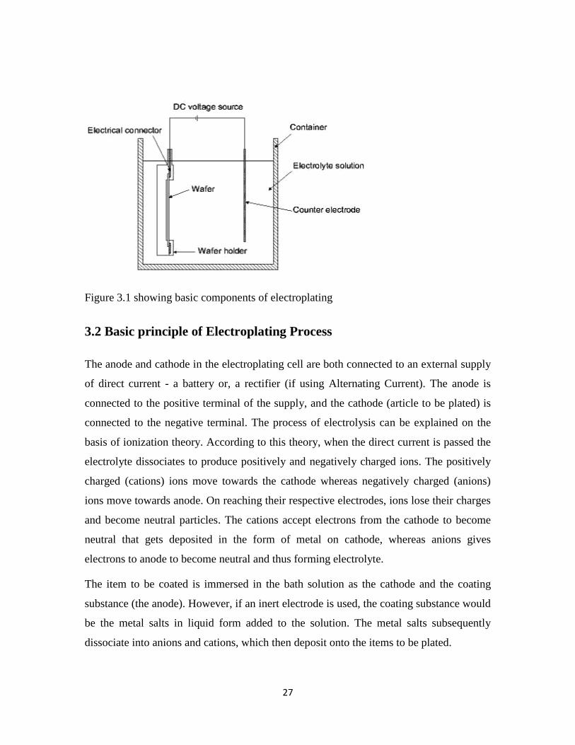
Figure 3.1 showing basic components of electroplating
3.2 Basic principle of Electroplating Process
The anode and cathode in the electroplating cell are both connected to an external supply
of direct current - a battery or, a rectifier (if using Alternating Current). The anode is
connected to the positive terminal of the supply, and the cathode (article to be plated) is
connected to the negative terminal. The process of electrolysis can be explained on the
basis of ionization theory. According to this theory, when the direct current is passed the
electrolyte dissociates to produce positively and negatively charged ions. The positively
charged (cations) ions move towards the cathode whereas negatively charged (anions)
ions move towards anode. On reaching their respective electrodes, ions lose their charges
and become neutral particles. The cations accept electrons from the cathode to become
neutral that gets deposited in the form of metal on cathode, whereas anions gives
electrons to anode to become neutral and thus forming electrolyte.
The item to be coated is immersed in the bath solution as the cathode and the coating
substance (the anode). However, if an inert electrode is used, the coating substance would
be the metal salts in liquid form added to the solution. The metal salts subsequently
dissociate into anions and cations, which then deposit onto the items to be plated.

28
3.3 Quantitative aspects of Electrolysis
The relationship between the amounts of substances liberated at the electrodes during
electroplating was explained by Michael Faraday (1833) in the form of two laws:
3.3.1 Faraday’s First Law
It states that amount of chemical reaction enhance the mass of any substance deposited or
liberated at any electrode is directly proportional to the quantity of electricity passed
through the electrolyte.
Thus, if W gram of a substance is deposited in passing Q coulombs of electricity, then
W ∞ Q
Or, W= EQ ------------- (1)
Where, E is constant of proportionality called as electrochemical equivalent of metal to
be deposited.
If current of I amperes is passed for t seconds then equation (1) becomes:
W= E x I x t ------------- (2)
Electrochemical equivalent can be estimated by measuring mass of the substance
deposited on electrode when a current of 1 ampere is passed for 1 second.
3.3.2 Practical consideration in Electroplating
The above formula (2) applies to a reaction which works at 100% efficiency.
But, this is does not happen in practical situation. Therefore, the current efficiency k
needs to be introduced.
Thus, the equation becomes,
W = E x I x t x k ---------------- (3)
100
Now, introducing current density as Id in ampere/decimetre2
(amp/dm2) and converting
time into minutes.

29
Then, W = E x Id x A X t x k grams (g) -------------------- (4)
6000
Here, A = area in dm2
The above derived expression obtained for calculating the mass deposited on anode can
be verified by the means of a case study as follows.
3.3.3 Empirical Approach to Calculate Waste of Anode in Copper
Plating
A case study from plating in Moradabad is considered. Say unit A, is performing copper
plating operations. The plater is using Acid copper as electrolyte which has constituents
as copper sulphate and sulphuric acid.
Calculating the weight of copper deposited on the cathode using the following values.
Electrochemical equivalent for copper (E) = 1.186
Current density (I) = 1.076 amp/dm2
Time (t) = 60 minutes
Area (A) = 1 m2 =
100 dm2
Efficiency (k) = 95
Mass deposited (W) is given as:
W = 1.186 x 1.076 x 100 x 60 x 95
6000
W = 0.1213 kg/m2 ------------------- (5)
Now, the plating unit A is electroplating 40 objects per day
Plating area per day = 7.35 m2
Thus, the unit A is electroplating 2205 m2
per year (300 working days).
Thus, anode required by unit = 2205 x 0.1213 = 267.46 kg per year
On contrary, the copper as anode consumption per month is 30 kg. Hence, in reality 300
kg of copper as anode is utilized per year (assuming 300 working days or 25 working
days in a month)

30
Electroplating Conversion efficiency = (267.46 x 100)/300
Thus, the actual conversion is 89.1%. Thus, 10.9% of copper anode is lost.
3.3.4 The Faraday’s second law
It electrolysis states that, when the same quantity of electricity is passed through different
electrolytes connected in series, the weights of the substances deposited at the cathodes
are directly proportional to their equivalent weights.
Numerically, it can be expressed as,
Weight of metal1 deposited = equivalent weight of metal 1 ------------------- (6)
Weight of metal 2 deposited equivalent weight of metal 2
3.4 Optimal Operating Conditions of Electroplating Process
The efficiency of electroplating depends on many factors, which are discussed below:
3.4.1 Temperature
The electroplating process is often exothermic in nature that leads to increase in
temperature of plating bath. Though, high temperature has beneficial effect and gives the
material crack-free coating, but, also excessive bath temperature reduces the rate of
electroplating process and thus, results in formation of soft dull deposit. There is a need
to keep the temperature suitable according to material to be plated, that is neither too high
nor too less for efficient plating.
3.4.2 Cathode current density
Optimal current density is directly proportional to the bath temperature. Higher is a
temperature more the current density is required. Very low current density decreases
effectiveness of the plating process. Too high current density may cause burning.
31
3.4.3 Anodes
The ratio of surface area of anode to cathode varies between 1-2. Properly operating
anodes are coated with dark brown lead peroxide. If an anode has lighter color (yellow-
orange) it should be cleaned.
3.4.4 Power supply
Power supply should be maintained constant during the process. Ripple should not be
more than 5%. High ripple exceeding 5% and current interruptions may cause dull or
even laminated deposit.
3.4.5 Agitation
Agitation helps to maintain the temperature of bath, which is a pre-requisite condition for
electroplating process. It can be done mechanically or by clean air.
3.4.6 Filtration
Continuous filtration of plating baths with filters or active carbon filters helps for
removal of foreign particles and organic contaminations (products of brightener
decomposition etc). It helps in sustaining the life of plating bath solutions. This will
increase the efficiency of the electroplating process. The filtration pumps should turn
over the solution a minimum 1-2 times tank volume per hour.

32
33
CHAPTER - 4
Steps for Electroplating process
4.1 Main constituents of Electroplating Process:
Majority of metal finishing operations typically involve four principal work steps or
process operations which are listed below:
1 Surface preparation
2 Pre-treatment
3 Electroplating
4 Post - treatment
4.2 Surface preparation
Surface preparation though is not a part of electroplating process but is necessary for
ensuring strong and uniform adhesion of the coating on the substrate. It includes
smoothening of the substrate surface (item to be coated) before the plating operation.
Surface preparation includes only physical process and no chemicals are used. The
surface preparation namely buffing done by scrapper can be done either manually or
mechanically (as shown in table 4.1)
4.3 Pre-treatment
This process aims to prepare and remove the contaminants from the items for plating.
Contaminants includes:-
a) Oil
b) Grease
c) Dirt
d) Mineral oils (Rust protection oils, Cutting fluids, coolants)
e) Miscellaneous organic soils (paints, fingerprints)
f) Polishing compounds
g) Miscellaneous solid particles (dust, abrasive grits, chips)

34
h) Oxides, scale, smut, rust.
The different activities involved in pre-treatment methods are:
(i) Acid activation – By mild acids and strong acids
(ii) By chlorinated hydrocarbons
(iii) Electro cleaning – cleaning of electrodes by alkali and direct current
(iv) Ultrasonic cleaning- rarely used technique using high frequency sound waves.
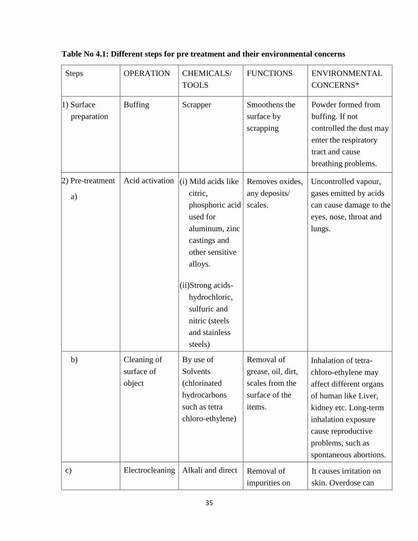
The details of surface preparation and pre-treatment, type of chemicals used with their
environmental concerns are summarized in Table no 4.1.
35
Table No 4.1: Different steps for pre treatment and their environmental concerns
Steps OPERATION CHEMICALS/
TOOLS
FUNCTIONS ENVIRONMENTAL
CONCERNS*
1) Surface
preparation
Buffing Scrapper Smoothens the
surface by
scrapping
Powder formed from
buffing. If not
controlled the dust may
enter the respiratory
tract and cause
breathing problems.
2) Pre-treatment
a)
Acid activation (i) Mild acids like
citric,
phosphoric acid
used for
aluminum, zinc
castings and
other sensitive
alloys.
(ii)Strong acids-
hydrochloric,
sulfuric and
nitric (steels
and stainless
steels)
Removes oxides,
any deposits/
scales.
Uncontrolled vapour,
gases emitted by acids
can cause damage to the
eyes, nose, throat and
lungs.
b) Cleaning of
surface of
object
By use of
Solvents
(chlorinated
hydrocarbons
such as tetra
chloro-ethylene)
Removal of
grease, oil, dirt,
scales from the
surface of the
items.
Inhalation of tetra-
chloro-ethylene may
affect different organs
of human like Liver,
kidney etc. Long-term
inhalation exposure
cause reproductive
problems, such as
spontaneous abortions.
c) Electrocleaning Alkali and direct Removal of
impurities on
It causes irritation on
skin. Overdose can

36
I.
II.
Anodic electro
cleaning
(reverse electro
cleaning)
Cathodic
electro
cleaning
(direct electro
cleaning
current
surface of anode
and cathode, solid
particles adhered
to the surface and
oxides.
cause damage to the
exposed part.
It can also alter the
salinity of soil
d) Ultrasonic
cleaning
high frequency
(20 – 45 kHz)
sound waves
Removing solid
particles, dirt and
smut.
3
Rinsing Water or De-
mineralized
water
Washing of
solvent/alkali/
acid/ chemicals
adhered during
pre-treatment
Water which contains
the residual of
chemicals in process of
washing is equally
harmful as chemicals.
This wastewater should
be treated before
disposal.
(Source: compiled from various documents)
The acids/alkali and solvents used for cleaning prove harmful to environment.
4.4 Electro Plating Process of different metals
The basic principle of electroplating has already been discussed in Chapter-3. In this
chapter, chemicals and substances used in electroplating of different metals will be
discussed. Selection of the chemicals used by electroplaters should take into account, the
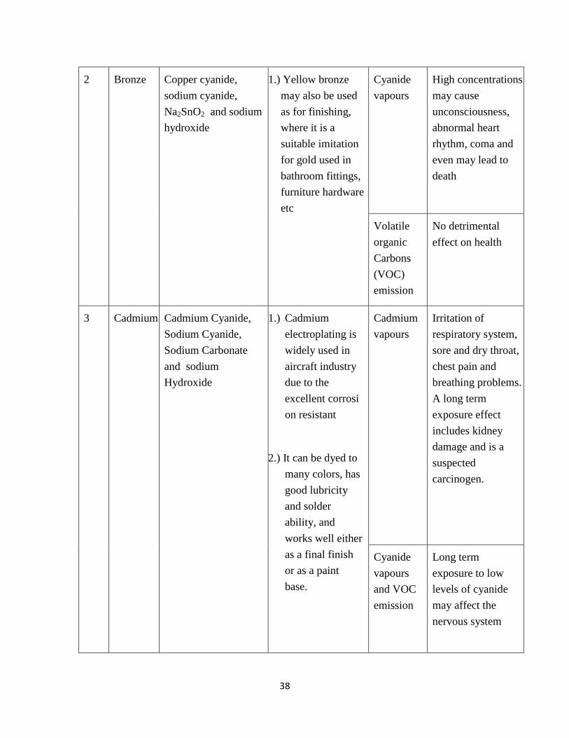
technology as well as finishing quality of object. Table 4.2 describes variety of chemicals

37
used for plating of different metals, and categorization of waste as well as the
environmental concerns of the process.
Table No. 4.2: Different types of Plating and their environmental concerns
S.No. Type of
Plating
Chemicals used as
electrolyte and
additives
Applications Waste
generated
Environmental
concerns
1 Brass (i) Sodium cyanide,
copper cyanide,
zinc cyanide and
Sodium carbonate
(ii) Alkaline
pyrophosphate
tartarate and
Histidine
1.) Brass plating is
used in coating
on steel wire
cord, used in
tyres as it
provides good
adhesion to steel
and rubber.
2.) Gold-colored
brass often is
used as a
decorative.
3.) It is also used in
parts in
engineering
finishes.
Cyanide
vapours
Cyanide being
highly poisonous
may affect the
biota. Also, cyanide
vapours emitted
may causes
headache, nausea,
dizziness and
difficulty in
breathing
38
2 Bronze Copper cyanide,
sodium cyanide,
Na2SnO2 and sodium
hydroxide
1.) Yellow bronze
may also be used
as for finishing,
where it is a
suitable imitation
for gold used in
bathroom fittings,
furniture hardware
etc
Cyanide
vapours
High concentrations
may cause
unconsciousness,
abnormal heart
rhythm, coma and
even may lead to
death
Volatile
organic
Carbons
(VOC)
emission
No detrimental
effect on health
3 Cadmium Cadmium Cyanide,
Sodium Cyanide,
Sodium Carbonate
and sodium
Hydroxide
1.) Cadmium
electroplating is
widely used in
aircraft industry
due to the
excellent corrosi
on resistant
2.) It can be dyed to
many colors, has
good lubricity
and solder
ability, and
works well either
as a final finish
or as a paint
base.
Cadmium
vapours
Irritation of
respiratory system,
sore and dry throat,
chest pain and
breathing problems.
A long term
exposure effect
includes kidney
damage and is a
suspected
carcinogen.
Cyanide
vapours
and VOC
emission
Long term
exposure to low
levels of cyanide
may affect the
nervous system
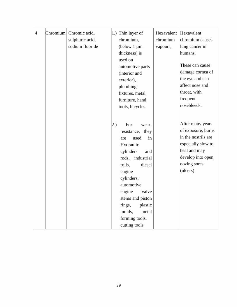
39
4 Chromium Chromic acid,
sulphuric acid,
sodium fluoride
1.) Thin layer of
chromium,
(below 1 µm
thickness) is
used on
automotive parts
(interior and
exterior),
plumbing
fixtures, metal
furniture, hand
tools, bicycles.
2.) For wear-
resistance, they
are used in
Hydraulic
cylinders and
rods, industrial
rolls, diesel
engine
cylinders,
automotive
engine valve
stems and piston
rings, plastic
molds, metal
forming tools,
cutting tools
Hexavalent
chromium
vapours,
Hexavalent
chromium causes
lung cancer in
humans.
These can cause
damage cornea of
the eye and can
affect nose and
throat, with
frequent
nosebleeds.
After many years
of exposure, burns
in the nostrils are
especially slow to
heal and may
develop into open,
oozing sores
(ulcers)

40
5 Copper (i) Copper cyanide,
sodium cyanide,
sodium hydroxide
and sodium
carbonate
1) The process is used
primarily in
printed wire board
manufacturing
and
electroforming
operations
Cyanide
vapours
Cyanide vapours
emitted may
causes headache,
nausea, dizziness
and difficulty in
breathing.
VOC
emission
No detrimental
effect
It can cause
serious damage to
the eyes, nose,
throat and lungs
Chronic exposure
of HF can
discolour, damage
tooth enamel
1) Copper
pyrophosphate, Pot
assium
Pyrophosphate and
Ammonium
Hydroxide
2) Copper sulphate
and Sulphuric acid
Acid mist
3) Copper
Fluoroborate ,
Fluoroboric Acid,
Boric Acid and
hydrofluoric (HF)
acid
Hydrogen
Flouride
(HF)
vapours
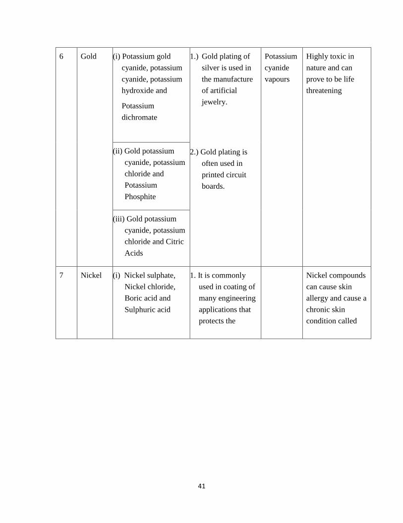
41
6 Gold (i) Potassium gold
cyanide, potassium
cyanide, potassium
hydroxide and
Potassium
dichromate
1.) Gold plating of
silver is used in
the manufacture
of artificial
jewelry.
2.) Gold plating is
often used in
printed circuit
boards.
Potassium
cyanide
vapours
Highly toxic in
nature and can
prove to be life
threatening
(ii) Gold potassium
cyanide, potassium
chloride and
Potassium
Phosphite
(iii) Gold potassium
cyanide, potassium
chloride and Citric
Acids
7 Nickel (i) Nickel sulphate,
Nickel chloride,
Boric acid and
Sulphuric acid
1. It is commonly
used in coating of
many engineering
applications that
protects the
Nickel compounds
can cause skin
allergy and cause a
chronic skin
condition called

42
(ii) Nickel
Sulphamate,
Nickel chloride
and Boric acid
material from
corrosion.
Applications
include oil field
valves, rotors,
drive shafts, paper
handling
equipment, fuel
rails and optical
surfaces for
diamond turning
etc
2. It is also used
in door
knobs, kitchen
utensils,
bathroom fixtures,
electrical/mechan
ical tools and
office equipment.
3.) It is also
commonly used
as a coating in
electronics (print
ed circuit
board manufactu
ring)
Nickel
sulphate
fumes,
Acid mist
Hydrogen
fluoride
vapours
"nickel itch"
Nickel fumes have
been proven to
cause nasal and
sinus cancers.
Hydrogen chloride
vapours can
discolor the teeth,
and both sulfuric
and hydrochloric
vapours can also
cause erosion of
the enamel in
exposed teeth
Hydrogen fluoride
vapours cause
digestive
disorders,
including nausea,
vomiting,
abdominal cramps
and diarrhea

43
Nickel chloride,
hydrochloric acid and
Boric acid
Nickel flouborate,
Nickel chloride and
Boric acid
Nickel sulphate,
ammonium chloride
and boric acid
8 Palladium Palladium chloride,
ammonium chloride,
hydrochloric acid
1.) Palladium plating
can be used on
watches, jewelry
and phones due
to its bright and
shiny
appearance, good
corrosion
resistance and
wear resistance.
2.) Palladium nickel
plating can be
used for
electronic parts
as it is cheaper
than gold.
Ammonia
vapour and
Acid mist
Vapours and mists
released by acid
baths can dissolve
in the moist tissue
of the eyes, nose,
throat and lungs,
and cause irritation
and burns of the
tissues

44
9 Platinum (i) Hexachloro
platinum,
Ammonium
phosphate,
Ammonium
hydroxide
Hydrogen
(ii) Dinitrosulphatoplat
inate (II) solution
and Sulphuric acid
1.) Platinum plating
is used for
catalytic
converters
(automotive),
surgical and
medical
equipment, and
low voltage, low
current
applications.
2.) Platinum plating
is also used for
anodes and for
protecting
substrates from
harsh chemical
environments.
Platinum
vapours
Ammonia
vapours
It causes
respiratory
allergies. Diseases
such as
conjunctivitis,
dermatitis, asthma,
urticaria etc.
Ammonia gas
emits vapors that
are suffocating and
can lead to serious
health problems,
even death.
10 Rhodium Rhodium sulphate
and Sulphuric acid
1.) Rhodium plating
is most
commonly found
in jewelry like
rings, bracelets,
necklaces, and
other forms of
jewelry in order
to increase the
longevity of the
item and
improve its
quality.
Rhodium
vapours
Contact dermatitis
( skin related
problem) have
been reported in
workers

45
2.) Rhodium plating
can be used on
circuits and other
metal objects to
prevent corrosion
and reduce the
effects of high
temperatures.
Acid mist
11 Silver (i) Silver potassium
cyanide, Copper
cyanide and
Potassium
cyanide
(ii) Silver potassium
cyanide,
Disodium
hydrogen
phosphate,
Phosphoric acid
(iii) Silver, Potassium
carbonate,
Succinamide
(iv) Silver iodide,
Sodium iodide,
Polyvinyl
alcohol, Sodium
thiosulfate
1.) The most common
usage of silver
plating is for
ornamentation of
jewellery, plates,
cups, trophies and
medals.
2.) The plating helps
in reducing
friction and to
improve paint
adhesion. It is
good for
conductivity and
provides a shield
against radiation.
4.) Silver finds
application in
electronics as a
replacement for
gold. Variable
capacitors
require silver
plating
Cyanide
vapours
Potassium cyanide
vapours can cause
death.
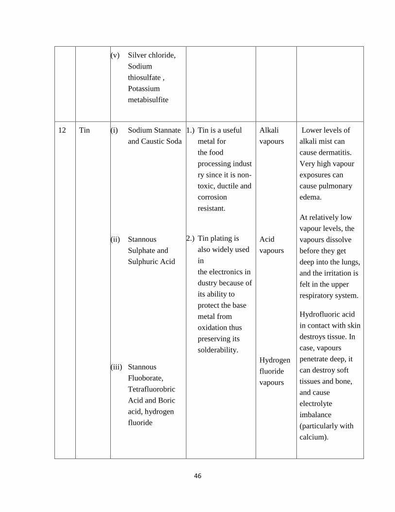
46
(v) Silver chloride,
Sodium
thiosulfate ,
Potassium
metabisulfite
12 Tin (i) Sodium Stannate
and Caustic Soda
(ii) Stannous
Sulphate and
Sulphuric Acid
(iii) Stannous
Fluoborate,
Tetrafluorobric
Acid and Boric
acid, hydrogen
fluoride
1.) Tin is a useful
metal for
the food
processing indust
ry since it is non-
toxic, ductile and
corrosion
resistant.
2.) Tin plating is
also widely used
in
the electronics in
dustry because of
its ability to
protect the base
metal from
oxidation thus
preserving its
solderability.
Alkali
vapours
Acid
vapours
Hydrogen
fluoride
vapours
Lower levels of
alkali mist can
cause dermatitis.
Very high vapour
exposures can
cause pulmonary
edema.
At relatively low
vapour levels, the
vapours dissolve
before they get
deep into the lungs,
and the irritation is
felt in the upper
respiratory system.
Hydrofluoric acid
in contact with skin
destroys tissue. In
case, vapours
penetrate deep, it
can destroy soft
tissues and bone,
and cause
electrolyte
imbalance
(particularly with
calcium).
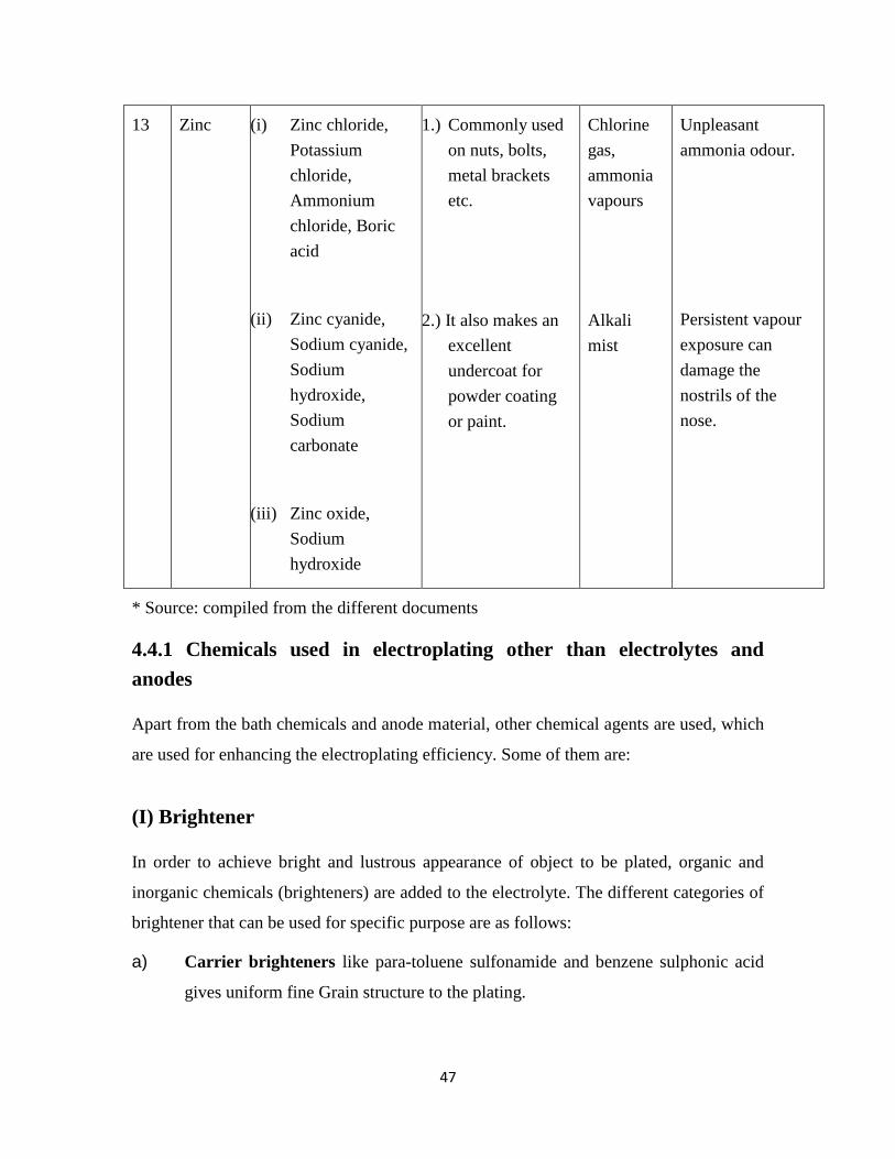
47
13 Zinc (i) Zinc chloride,
Potassium
chloride,
Ammonium
chloride, Boric
acid
(ii) Zinc cyanide,
Sodium cyanide,
Sodium
hydroxide,
Sodium
carbonate
(iii) Zinc oxide,
Sodium
hydroxide
1.) Commonly used
on nuts, bolts,
metal brackets
etc.
2.) It also makes an
excellent
undercoat for
powder coating
or paint.
Chlorine
gas,
ammonia
vapours
Alkali
mist
Unpleasant
ammonia odour.
Persistent vapour
exposure can
damage the
nostrils of the
nose.
* Source: compiled from the different documents
4.4.1 Chemicals used in electroplating other than electrolytes and
anodes
Apart from the bath chemicals and anode material, other chemical agents are used, which
are used for enhancing the electroplating efficiency. Some of them are:
(I) Brightener
In order to achieve bright and lustrous appearance of object to be plated, organic and
inorganic chemicals (brighteners) are added to the electrolyte. The different categories of
brightener that can be used for specific purpose are as follows:
a) Carrier brighteners like para-toluene sulfonamide and benzene sulphonic acid
gives uniform fine Grain structure to the plating.
48
b) Levelers namely allyl sulfonic acid, formaldehyde chloral hydrate produce are
added in combination with carrier brighteners for brilliant deposit.
c) Inorganic brighteners such as cobalt, zinc gives additional luster to the coating
of metal.
(II) Wetter
Wetter is used as an anti-pitting agent used in electrolyte with low foaming
characteristics which enables it to function equally well in air-agitated or mechanically
agitated solutions.
The action of Wetter significantly lowers surface tension of electrolyte, allowing the
plating solution to spread uniformly, and provide intimate contact with the surface of
metal being plated. As a result, pitting caused by formation of hydrogen bubbles on
cathode or other organic contaminations are greatly reduced, or eliminated. E.g. sodium
lauryl sulfate
In addition to its effective wetting action, it provides other operational benefits. It does
not co-deposit with the metal plate and thus, do not affect deposit characteristics.
4.4.2 Problems faced in using different electrolytes in electroplating
The environmental concerns have been discussed in Table 4.4. Besides, environmental
concerns there are some operational problems for different electrolytes used in plating of
different metals. Some of these problems have finite solutions while other remains
unsolved. These concerns are discussed below:
Problems such as choosing of non-cyanide solution over cyanide solutions on the cost of
its dull deposit affects the cost of plated object, needs to be consulted by an expert.
1) Concern: Alkaline cyanide baths are used from past to till date are used in
electroplating. The problem having the alkaline cyanide bath that for obtaining
consistent deposit of metals high current densities is required. This affects the cost
of the electroplating process.

49
Action: Hence, platers should use the alkaline cyanide bath for flash deposits of
metal (thin layer).
2) Concern: Traditionally, Cyanide has been used as plating solutions in
electroplating Industries. Being, hazardous to the health of humans and thus, has
serious environmental concerns (air, water and soil) (refer to Table 4.2).
Action: Hence, Environmental and safety considerations have stimulated the
development of cyanide-free plating formulations. Some of these non-cyanide
processes have been already implemented in the electroplating industry. A
cyanide-zinc solution can be replaced with a non-chelated alkaline zinc solution
(Meltzer et al.,, 1990). Non-cyanide cadmium baths are now available to replace a
cyanide cadmium bath (Higgins, 1989)
3) Concern: The gold colored brass often use as a decorative has the problem of
tarnishing (dull brightness) after plating.
Action: The conventional solution to this problem is application of a protective
layer of clear transparent powder coat or lacquer to give brighter look.
4) Concern: Non-cyanide solutions used in electroplating have insufficient colour in
the deposits and thus insufficient color. Moreover, the process using non cyanide
solution work in narrow operating range (Fujiwara 1993b).
Action: Some additives can be added to non cyanide solutions to maintain the
quality of the deposit (For example, additive Histidine is added to Brass
pyrophosphate solution for maintaining the conventional quality of brass plating).
5) Concern: The main disadvantage of copper pyrophosphate is that the preparation
of electrolyte is quite expensive and wastewater produced after plating is harder to
treat (Braun Intertec 1993).
6) Concern: Acidic plating bath solutions (For example, Copper plating) have low
pH which can attack the object to be plated (Braun Intertec, 1992).

50
7) Concern: Flouborate bath solutions have fluoride ions which are chemically
active and attcks the portion of object which is not to be plated.
Action: In order to prevent areas from unwanted plating from fluoride, they
should be masked.
8) Concern: Trivalent chromium (Cr3+
) is formed in electroplating process of
chromium. Normal level of the trivalent chromium is about 1-2% of the chromic
acid concentration. Ions of trivalent chromium continuously re-oxidize to the
hexavalent state at the anode. But, higher contents of trivalent chromium (more
than 2%) may cause:
Reduction in Throwing power which causes reduction in plating rate
Treeing of the deposit.
Action: If the trivalent chromium is too high, re-oxidation operation should be
carried out at high anode area/cathode area ratio at specific current density.
4.5 Post Plating Treatment
After performing the plating process, most of the plated objects require post treatment
operations. The purpose of Post treatment operations are:
To enhance the physical appearance of the item.
To improve the corrosion resistance of the item.
For enhancing the aesthetic values.
Post plating treatment includes different techniques as following:
1) Sealing
Sealing is conducted in hot water at a temperature about 200ºF (93ºC). It is done
in order to trap the dye which is located in the pores from leaking and prevent
absorption of undesired molecules in the pores. The crystals seal the pores
opening. Anodize coatings used for application of paints and adhesives.

51
2) Dying
Dying is a process of absorption of organic or inorganic molecules in the pores of
object after plating. Dying provides excellent decorative appearance to the plated
object. The dye fills the pores and gives color to the coating of plated object.
3) Conversion Coating
It is a process of formation of a film of chemical compound on the object surface
to prevent corrosion and to limit the growth of salts which may harm due to
corrosion. This reaction differs from a conventional coating applied on the
substrate surface as it does not change its chemical state. In conversion coating,
heavy metals are used as in their high valence state, since they have the ability to
prevent corrosion. For eg vanadium, molybdenum, tungsten etc.
Types of conversion coating depending upon the requirement of properties are as
follows:
a) Phosphating
Phosphate coating (phosphating) is a conversion coating consisting of an
insoluble crystalline metal-phosphate salt formed in a chemical reaction
between the substrate metal and a phosphoric acid solution containing ions
of metals (zinc, iron or magnesium).
Zinc phosphate coating is applied when high corrosion resistance is
required.
Iron phosphate coating is applied when strong adhesion of a subsequent
painting is required.
Manganese phosphate coating is applied when wear resistance and anti-
galling properties are required. Manganese phosphate also possesses the
ability to retain oil, which further improves anti-friction properties and
imparts corrosion resistance to the coated parts.

52
b) Anodizing
Anodizing is an electrochemical process of forming conversion oxide
coating by oxidation of an anodically connected metal in an acidic
electrolyte solution. Anodizing is mostly used for aluminum. Other
commercially anodized metals are tantalum and niobium
c) Black oxide coating
In this process, molten baths are prepared (A mixture of sodium nitrate
(NaNO3) and potassium nitrate (KNO3) in equal ratio). The bath contains
molten oxidizing salts, in which oxygen reacts with iron atoms to form a
film of black oxide. It is least expensive of other treatments and gives
shiny black appearance which is stable at high temperatures. By this
process, there are minor dimensional changes with good lubricating
properties which make its application in automotive parts (bearings,
springs), cutting tools, gauges etc.
53
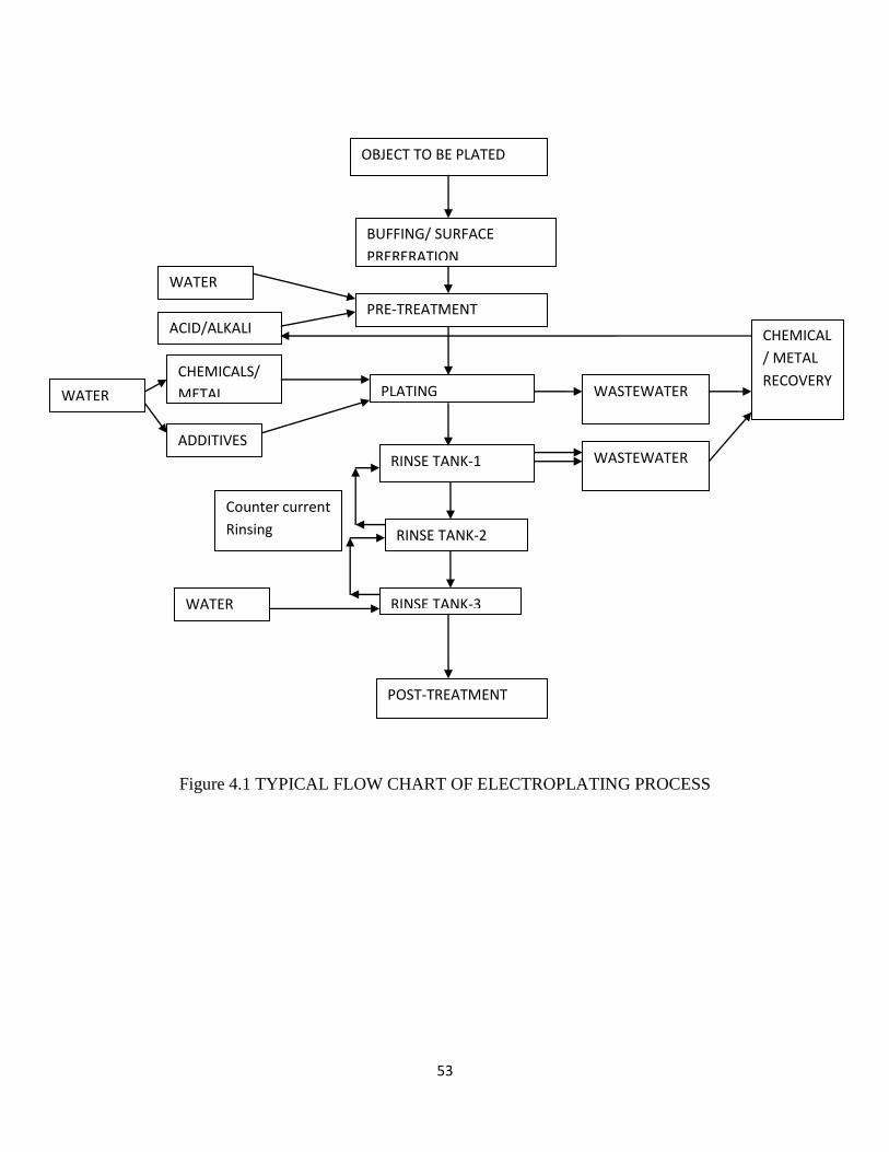
Figure 4.1 TYPICAL FLOW CHART OF ELECTROPLATING PROCESS
OBJECT TO BE PLATED
PRE-TREATMENT
PLATING
RINSE TANK-1
RINSE TANK-2
RINSE TANK-3
POST-TREATMENT
BUFFING/ SURFACE
PRERERATION
WASTEWATER
WATER
ACID/ALKALI
CHEMICALS/
METAL WATER
CHEMICAL
/ METAL
RECOVERY
WATER
ADDITIVES WASTEWATER
Counter current
Rinsing
54
CHAPTER - 5
Minimization of waste
5.1 Characterization of Waste generated from Electroplating Industry
Electroplating industry has been generating a huge amount of waste in the forms of
wastewater, spent solvent, spent process solutions and sludge (Freeman, 1988). The
industry of Electroplating generates wastes in different forms which are solid, liquid and
gaseous (Chapter-1) and has been declared under 17 major polluting industries in India
by CPCB. Hazardous waste is generated during different steps of the process.
5.1.1 Solid waste generated from the process
Solid waste includes residues such as cleaning powder; buffing compounds generated
during the pre-treatment process and spent anodes during the plating process (Chapter-4).
In addition to this, when any recovery system (that will be addressed in next chapter) is
used the solid waste is generated as spent resins when an Ion exchange method is used for
recovery, fouled membrane when RO process is used and clogged medium in case of
Electro dialysis.
5.1.2 Liquid wastes
The majority of the waste generated in electroplating process is in liquid form. They
pollute the environment more as compared to solids and gases and consequences of
uncontrolled affect the health seriously (Table 4.2).
On the basis of severity of the effects Central Pollution Control Board has categorized
them as Hazardous waste in schedule 1.
5.1.3 Characterization of Solid and Liquid wastes generated from
Electroplating Industry (by CPCB)
55
According to the Hazardous Waste (Management and Handling) Rules, 2002 and as
amended vide S.O. 593 (E) dated 20th May, 2003, the following wastes from
Electroplating Industry are identified and listed in Schedule 1 as:
1. Acid Residues
2. Alkali Residues
3. Rinse water from pre-treatment and plating operations.
4. Spent bath containing sulphide, cyanide and toxic metals
5. Sludge from bath containing organic solvents
6. Phosphate Sludge.
7. Etching residues.
8. Plating metal sludge
9. Chemical Sludge from wastewater treatment.
5.1.4 Characterization of Gaseous wastes generated from Electroplating
Industry
Gaseous emissions come from the plating bath due to high temperature or excessive
agitation. Gaseous emission may include the following wastes:
1. Vapours from Chlorinated solvents during pre-treatment
2. Volatile organic Compounds (VOCs)
3. Acid/ Alkali Mist
4. Vapours of Metals (such as Platinum, Hexavalent Chromium, Rhodium,
Cadmium etc)
5. Vapours of chemicals (e.g. Nickel sulfamate fumes, Potassium cyanide fumes etc)
6. Cyanide vapours from plating bath.
7. Hydrogen fluoride and Ammonia vapours.
In view of the above mentioned hazardous waste generated in electroplating process, the
need for controlling the waste generated is considered as the most important need of the
day. In view of its immense relevance, various techniques to control waste have been
developed.

56
Type
Solid Spent
anodes,
buffing
compounds,
spent
anodes,
spent resins
and fouled
membranes
(During
chemical
recovery),
sludge
Liquid Rinse water
from pre-
treatment
and plating
operations,
spent bath
containing
sulphide,
cyanide and
toxic metals
5.2 Waste Minimization in Electroplating Industry
Waste minimization occupies the topmost and most important position in management of
waste (John Pichtel, 2005).
The basic approach that can be applied to minimize the waste are:
5.4.3 Minimizing the resource use

57
This is the very first step to be followed for minimizing the waste. The cost of the process
depends heavily on the initial planning required for the purchase of raw material termed
as Inventory Planning.
Usually, the raw material is purchased in excess due to lack of planning that results in:
a) Purchase of excess of raw material remains unused and thus enhances the cost of
process.
b) In case of excess of raw material there is a tendency to overuse the surplus raw
material. This will lead to higher generation of waste.
5.4.4 Modifying the process
The use of machines or electronic sensors can improve over the process using the
manpower.
5.4.4.1 The use of sensors
Water level sensors are present to indicate level of water in tanks instead of human
intervention will definitely improve the efficiency of the process. By modifying the
process, the efficiency of process can be increased and waste generation can be
minimized.
5.4.4.2 Use of suitable plating baths
The simple way of calculating amount of electrolyte using basic principle of chemistry
can help in deciding the size of bath. Thus, smaller size of bath (optimal range) will
reduce the waste generation.
5.4.4.3 Using sludge drier in place of using sludge press will minimize the waste stream.
5.4.5 Modifying the product.

58
Use of product substitution of certain chemicals is a better way to reduce hazardous
wastes. For eg. trichloro-ethylene is generated as small waste stream during pre-treatment
(Chapter-4). Trichloroethylene is used to clean parts before plating. This can be easily
replaced by another solvent that cleans effectively i.e. Isopropyl alcohol. Another
example use of non cyanide alternatives over cyanide solutions produces less hazardous
waste.
Some of the techniques that can be adopted to minimize waste production in
electroplating industry are suggested as follows:
5.3 Minimization of drag–out losses
When plated parts are withdrawn from a plating process unit, they retain some part of the
plating bath solution, termed as “drag-out". The drag out that cause loss of material
should be minimized to save both chemicals and water used for rinsing. This process of
loss of drag out loss can be minimized in following ways:
(i) By providing sufficient drainage time so that excess of electrolyte falls in plating
tank and can be further reused.
(ii) Drain board system can be installed between the plating tank and rinse tanks. By
this way the excess of the solution dripping from object is collected and recycled
to plating tank.
(iii) Reducing the speed of withdrawal of object from bath tank to drag out tank.
(iv) The concentrations of process bath can be lowered. As it is evident, less
concentrated solution will require less amount of water for rinsing leading to
reduction in generation of wastewater.
(v) Use of surfactants (eg sodium lauryl, discussed in chapter-4) prevents the plating
solution to adhere to the object. Thus minimizing amount of drag out.
(vi) The temperature of plating bath can be increased (within the optimal range). The
increased temperature will decrease the viscosity of the plating process solution
and hence, less amount of the solution will stick to the object which can be easily
removed during rinsing.

59
5.4 Modified Rinsing techniques
Once the plating operation is over, the plated object is put in a Drag out tank.
Drag out tank is a rinse tank that is filled with pure water for rinsing the plated object.
Usually, more than one tank is available for rinsing. 90% of the water used in
electroplating industry is consumed in rinsing (estimate given by survey done in
Moradabad). We can minimize water use by providing different rinsing techniques.
5.4.1 Counter current rinsing
Countercurrent rinsing consists of serious of rinse tanks arranged in which the water
flows in the opposite direction of the work flow (dirtiest to cleanest). In order to
minimize the use of water required for rinsing, the water of the farthest tank (having least
concentration) is transferred to the preceding tank (having higher concentration in
comparison to succeeding tank) (figure 5.1). The transfer can be done by mechanical
valves, pumps or manually. This technique is termed counter flow (or countercurrent)
rinsing because the plated piece and the rinse water move in opposite directions.
The efficiency of counter current rinsing technique increases with the number of counter
flow rinse tanks (three-stage, four-stage, etc.) and lower the rinse rate needed for
adequate removal of the process solution from object. The technique of counter current
rinsing is generally not adopted in unorganized sectors. This was noticed during the
survey done at Moradabad where, the platers were having 2-3 tanks for rinsing but were
throwing the water of all the tanks. So, this technique can be recommended for
conserving water (Chapter-7).
5.4.1. Factors affecting Counter-current rinsing
The efficiency of counter current rinsing technique increases with the number of counter
flow rinse tanks (three-stage, four-stage, etc.) and lower the rinse rate needed for

60
adequate removal of the process solution from object. The rinse rate required for
adequate cleaning is governed by following factors:
(i) The concentration of plating chemicals in the drag-out.
(ii) The concentration of plating chemicals that can be allowed in the final rinse tank
(iii) The number of counter flow rinse tanks.
More typically, each added rinse stage reduces rinse water use by 50 percent.
5.4.1.2 Case study of counter current rinsing
Case study was done at Moradabad. Considering, a nickel plating unit B, was utilizing 2
rinse tanks for rinsing and consuming 2250 litres per day.
A typical Watts nickel plating solution contains 210000 mg/l(Ct), and the allowed final
rinse concentration(Cr) is 5 mg/l (Existing standards of plating).
Now, estimating the drag out rate of the electroplating process.
Typically, Nickel bath solutions of around 0.1 litre per sq. m. of plated area is lost as drag
out to the rinse tanks (COINDS)
Area plated by unit B per day = 7.776 m2
Hence, the drag out rate for Nickel plating = 7.776 x 0.1 = 0.7776 litres/day
Now, water requirement for rinsing per liter of drag out by the above equation (6) is
= 0.7776 x 204.93 = 159.3 litres/ day
Input concentration of object (Nickel electrolyte) = 210000 mg/l
Final concentration of object after rinsing = 5 mg/l
Considering, the input of water as y and the concentration of water = 0 mg/ litre
Concentration of water coming out after rinsing = z mg/ litre

61
Now, applying mass balance to the system,
Z
Now, the 2
Figure 5.1 Mass balance in two stage counter current system
Forming simultaneous equations from the system,
210000 x 0.7776 + y x 0 = 5 x 0.7776 + yz ------------------- (i)
z x 0.7776 + y x 0 = 5y + 5 x 0.7776 ---------------------------- (ii)
Solving (i) and (ii) simultaneous equations, we obtain the values as:
y = 159.2, z = 1025.71
Hence, water requirement is 159.2 litres per day
And, the concentration of water after rinsing = 1025.71 mg/l
210000 mg/l,
Flow rate = 0.7776l/day
Concentration = z mg/l
Water = y litres/day
Water = y l/day,
Concentration= 0 mg/l
5 mg/l,
Flow rate = 0.7776
l/day
5 mg/l,
Flow rate = y litres /day
5 mg/l,
Flow rate = y litres /day

62
Hence, for the electroplating unit B, 159.2 litres/ day is required instead of 2250
litres/day.
The mass flow of pollutants exiting the rinse system remains constant.
However, the pollutants are much more concentrated with a two-stage rinse system
(1025.71 mg/l) than with a single-tank rinse system (5 mg/l)
5.4.1.3 Estimation of cost for 2 stage Counter current rinsing
The cost of a new two stage counter-current rinse system is about Rs 25,000
(approximately). In addition to this aerator, Poly vinyl chloride (PVC) pipe and
connectors and mechanical flow control valves are also required.
The actual cost may be significantly higher depending on the modifications made to the
rinse tanks.
Components Cost (in Rupees)
200 litre tank x 2 (@ Rs 62.5 per litre) 25,000
Aerator 2600
Control valve 500
Pvc pipe and connectors 1000
Total Investment 29,100
Table 5.1 Cost of components of 2 stage counter current rinsing (Source: vendors)
5.4.1.4 Payback period in counter current rinsing
The payback period for installing a counter-current rinse tank will depend on the quantity
of water saved and the raw water costs.
In the above case, the two stage system is used to reduce the water flow from 2250
litres/day to 160 litres/day.
The water charges in industries, for the 25-50 kilo litre slab, one kilo litre will cost Rs 50
while consumption of every kilo litre above 50 and below 100 kilo litre will cost Rs 80.
Above 100 kilo litre, the rate is Rs 100 (Uttar Pradesh Jal Board)

63
Thus, consumption of water per year in case of flow rate 2250 litres/day the cost is Rs
67,500 while after reduction in flow rate (160 litres/day) the cost is reduced to Rs 2400
only.
Steps for calculating payback period
Reduction in cost after using counter current rinsing = 67500-2400 = Rs 65100
Amount saved per day (assuming 300 working days) = 65100/300 = Rs 217
Time taken to recover the cost of 2 stage counter current = total cost of equipment
Amount saved per day
= 29100/217 = 134.10 days ~ 134 days
= 134/25 = 5.3 months
Thus, the payback period of the whole system is 5.3 months ---------------- (7)
The savings will be Rs 65,000 per annum ------------------- (8)
5.4.1.5 Disadvantages of counter current rinsing
Counter flow rinsing systems are not without drawbacks. The negative aspects of counter
flow rinsing include:
(1) Cost of additional rinse tanks
(2) Loss of valuable production space
(3) Increase in production time/labor.
5.4.2 Spray Rinsing Technique
Spray rinsing is used to reduce drag-out losses and save rinse water. This includes,
rinsing done by spraying over the plating tanks and removes the excess of the electrolyte
which drips out in the plating tank itself. In this manner, the electrolyte is replenished.
But, the major drawback is that electrolyte gets diluted if spraying is done over the tank.
In order to overcome this problem, the process was modified and separate spray rinse
tanks (drag out tank) with single or multiple rinses were suggested.
64
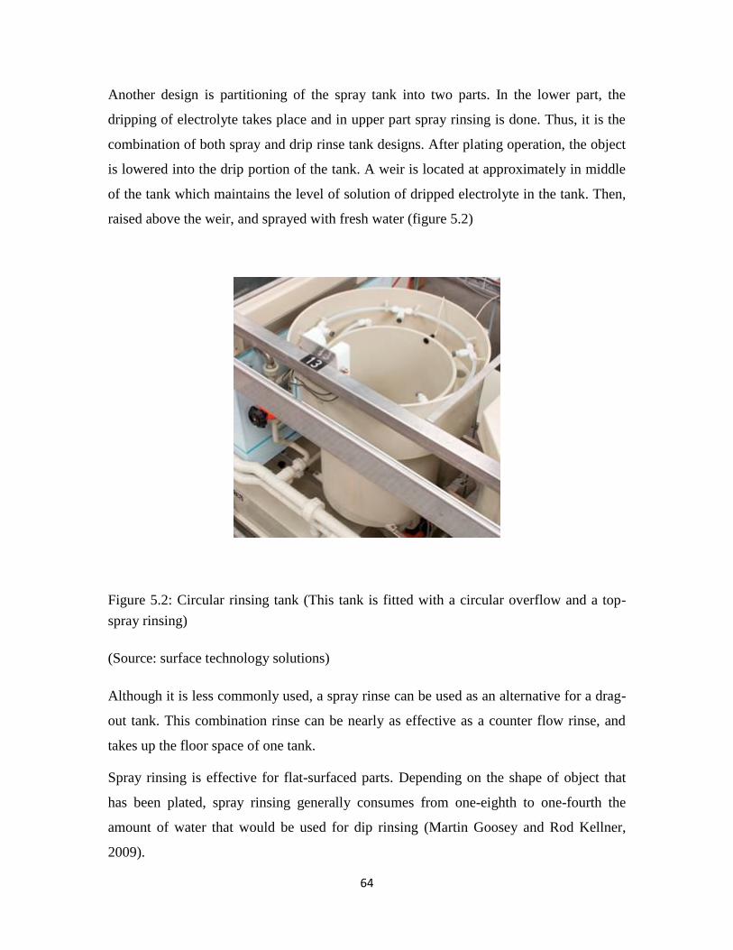
Another design is partitioning of the spray tank into two parts. In the lower part, the
dripping of electrolyte takes place and in upper part spray rinsing is done. Thus, it is the
combination of both spray and drip rinse tank designs. After plating operation, the object
is lowered into the drip portion of the tank. A weir is located at approximately in middle
of the tank which maintains the level of solution of dripped electrolyte in the tank. Then,
raised above the weir, and sprayed with fresh water (figure 5.2)
Figure 5.2: Circular rinsing tank (This tank is fitted with a circular overflow and a top-
spray rinsing)
(Source: surface technology solutions)
Although it is less commonly used, a spray rinse can be used as an alternative for a drag-
out tank. This combination rinse can be nearly as effective as a counter flow rinse, and
takes up the floor space of one tank.
Spray rinsing is effective for flat-surfaced parts. Depending on the shape of object that
has been plated, spray rinsing generally consumes from one-eighth to one-fourth the
amount of water that would be used for dip rinsing (Martin Goosey and Rod Kellner,
2009).
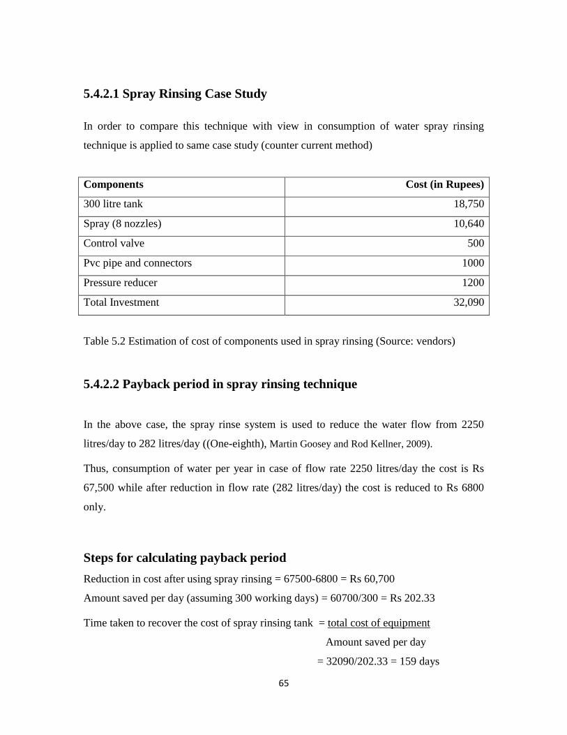
65
5.4.2.1 Spray Rinsing Case Study
In order to compare this technique with view in consumption of water spray rinsing
technique is applied to same case study (counter current method)
Components Cost (in Rupees)
300 litre tank 18,750
Spray (8 nozzles) 10,640
Control valve 500
Pvc pipe and connectors 1000
Pressure reducer 1200
Total Investment 32,090
Table 5.2 Estimation of cost of components used in spray rinsing (Source: vendors)
5.4.2.2 Payback period in spray rinsing technique
In the above case, the spray rinse system is used to reduce the water flow from 2250
litres/day to 282 litres/day ((One-eighth), Martin Goosey and Rod Kellner, 2009).
Thus, consumption of water per year in case of flow rate 2250 litres/day the cost is Rs
67,500 while after reduction in flow rate (282 litres/day) the cost is reduced to Rs 6800
only.
Steps for calculating payback period
Reduction in cost after using spray rinsing = 67500-6800 = Rs 60,700
Amount saved per day (assuming 300 working days) = 60700/300 = Rs 202.33
Time taken to recover the cost of spray rinsing tank = total cost of equipment
Amount saved per day
= 32090/202.33 = 159 days

66
= 159/25 = 6.3 months
Thus, the payback period is 6.3 months ----------------------- (9)
The cost savings are Rs 60,000 per annum ------------------- (10)
On comparison of (7), (8), (9) and (10) it was established that that counter current
technology saved Rs 65,000 and payback period is 5.3 months, whereas the spray rinsing
saved Rs 60,000 and its payback period is 6.3 months. Thus, counter current technique
proved to be better from economic point of view.
5.4.2.3 Problems in spray rinsing
1) The most important drawback, which prevents spray rinsing use is that, the
chemical recovered after spray rinsing has many contaminations such as
brighteners, additives, grease etc, that requires to be separated/purified before the
chemical recovered is recycled to the plating bath
2) It is less effective with recessed and hidden surfaces.
3) The design of spray rinses must consider the size and shape of the part. Spray
nozzles are available in many sizes and spray patterns, and should be selected
appropriately.
4) Higher spray velocities may require pumping.
67
CHAPTER - 6
Chemical Recovery
6.1 Rationale of Chemical recovery
During electroplating process, electrolyte is consumed partly in deposition of metals on
cathode and other part is lost in rinsing of the plated object. The major part of electrolyte
is lost in drag out, containing metals (Nickel, silver, copper etc). This flows down as
waste in the rinsing process. This wastewater containing the metals and chemicals require
strict procedures for treatment and disposal.
The plating bath solution needs to be discarded after some rounds of plating because of
increase in impurities that reduces the efficiency of plating process and cause
deterioration in quality of deposit. This causes waste in monetary terms and has
environmental concerns.
6.2 Different techniques of Chemical/Metal Recovery
Recovery of metals and chemicals from the wastewater generated by rinsing plays an
important role in reducing the cost of process and reduce the environmental concerns as
well. The recovery of metals or chemicals can be done by adopting various methods.
These methods are briefly described below with their specific advantages and
disadvantages.
6.2 .1 Evaporation method for Chemical recovery
This is the most convenient and traditional form of chemical recovery.
As more and more plates are rinsed, the concentration of chemicals in the rinse tanks
increases due to drag out of plated objects. After some rounds of rinsing, the
concentration of chemicals in rinse tanks rises to such an extent that it appears to be
equivalent to that of plating bath. In order to make water in rinse tank suitable for
68
recycling process of evaporation is used. The concentrated chemicals can be recycled in
plating bath via pump.
6.2.1.1 Fundamental principle underlying Evaporation process
Every chemical solution is made up of at least one or more solvent, and one or more
dissolved materials known as solute. Water is the major solvent used and also for various
other processes in different processes in the electroplating industry. Most of the
chemicals used by the metal finishing industry are water soluble. Most solvents,
including water, have high vapour pressures. Most of the metallic salts used for plating is
non-volatile (not vaporize easily), even if heated to very high temperatures. The wide
difference in vapor pressure (or relative volatility) between water and bath chemicals
facilitate separation of bath drag-out from rinse water (For example, Nickel has boiling
point of 3500ºC while water has 100ºC). This becomes the underlying principle for
chemical recovery by evaporation.
6.2.1.2 Process of Evaporation using Atmospheric Evaporator
Atmospheric evaporators consist of air stream to strip water as vapour from rinse tank.
Evaporation takes place at room temperature. The air pressure exerted by evaporator
increases the rate of evaporation at room temperature and this enables the separation of
water from chemicals in drag out. They are widely used by industry because of their low
cost and simple operating procedure. Atmospheric evaporator units are used as single or
in multiples to dewater plating rinse waters to recover bath concentrate. After removing
excess of water from the rinse tanks, the chemicals recovered are recycled to plating bath
with the help of a pump.
6.2.1.3 Atmospheric Evaporators Case Study
To illustrate the effectiveness of chemical recovery using atmospheric evaporator a case
study was taken from a plating unit C operating in Moradabad.
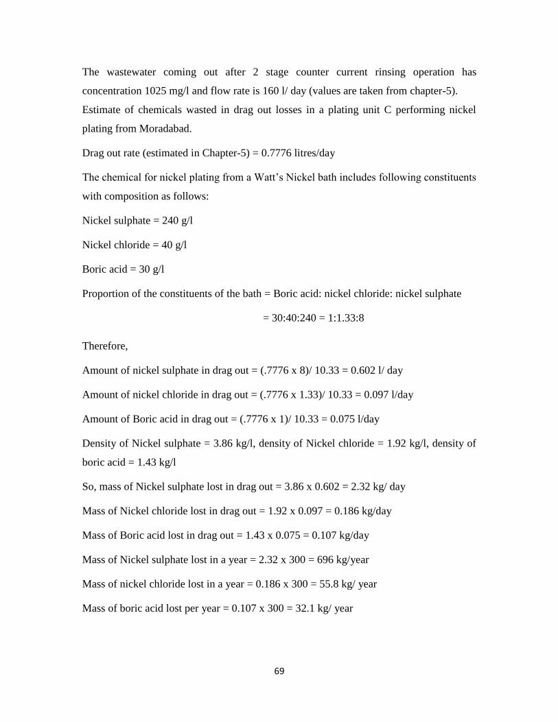
69
The wastewater coming out after 2 stage counter current rinsing operation has
concentration 1025 mg/l and flow rate is 160 l/ day (values are taken from chapter-5).
Estimate of chemicals wasted in drag out losses in a plating unit C performing nickel
plating from Moradabad.
Drag out rate (estimated in Chapter-5) = 0.7776 litres/day
The chemical for nickel plating from a Watt’s Nickel bath includes following constituents
with composition as follows:
Nickel sulphate = 240 g/l
Nickel chloride = 40 g/l
Boric acid = 30 g/l
Proportion of the constituents of the bath = Boric acid: nickel chloride: nickel sulphate
= 30:40:240 = 1:1.33:8
Therefore,
Amount of nickel sulphate in drag out = (.7776 x 8)/ 10.33 = 0.602 l/ day
Amount of nickel chloride in drag out = (.7776 x 1.33)/ 10.33 = 0.097 l/day
Amount of Boric acid in drag out = (.7776 x 1)/ 10.33 = 0.075 l/day
Density of Nickel sulphate = 3.86 kg/l, density of Nickel chloride = 1.92 kg/l, density of
boric acid = 1.43 kg/l
So, mass of Nickel sulphate lost in drag out = 3.86 x 0.602 = 2.32 kg/ day
Mass of Nickel chloride lost in drag out = 1.92 x 0.097 = 0.186 kg/day
Mass of Boric acid lost in drag out = 1.43 x 0.075 = 0.107 kg/day
Mass of Nickel sulphate lost in a year = 2.32 x 300 = 696 kg/year
Mass of nickel chloride lost in a year = 0.186 x 300 = 55.8 kg/ year
Mass of boric acid lost per year = 0.107 x 300 = 32.1 kg/ year

70
Evaporative systems recover valuable resources, conserve waste-treatment chemicals,
and minimize the production of metal hydroxide sludge. Unlike chemical treatment,
evaporative recovery provides users a return on investment and helps to lower plating
cost [Howard (1982)].
Evaporative recovery systems have proven to be reliable, effective and economical in
more than 30 years of field experience. Today's systems are compact, economically
efficient, and offer microprocessor-based controls. The economic benefits of such
evaporator recovery systems include:
Partial, open-loop recovery of 90 percent of plating solution.
Savings in treatment chemicals because only 10 percent of the drag out needs
waste treatment.
Hence, with atmospheric evaporation the losses of plating chemicals in drag out are
reduced to:
Nickel sulphate = 69.6 kg/year
Nickel chloride = 5.58 kg/year
Boric acid = 3.21 kg/year
Chemicals consumption per month (data taken from Moradabad) = 250kg/month,
6.2.1.3.1 Estimation of cost for atmospheric evaporator
Calculating energy cost
The amount of energy required is roughly 1000 British thermal units (BTU) per pound
mass of water evaporated, regardless of whether the evaporation is conducted at
atmospheric pressure [William (1998)].
1000BTU /0.45 kg= 2222.22 BTU/kg
Water to be evaporated in one day = 160 kg
So, 160 kg of water will require = 160 x 2222.22= 355555.56 BTU
Yearly consumption (300 working days) = 300 x 355555.56 = 106666666.7 BTU
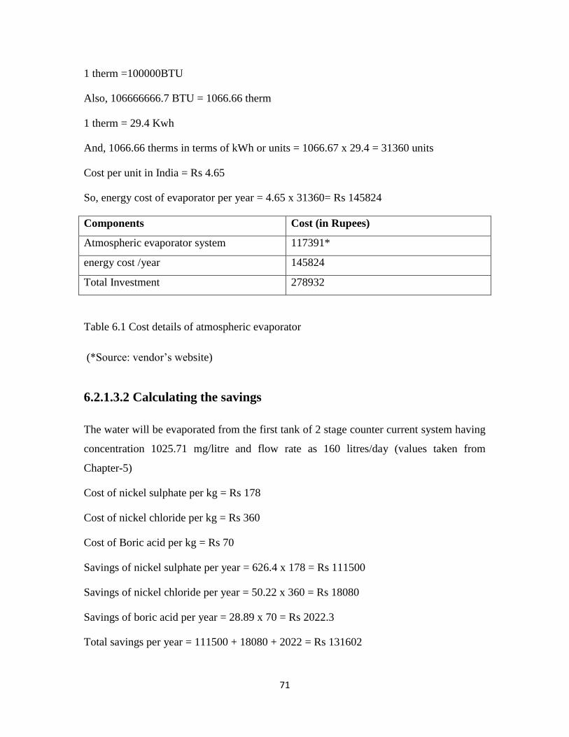
71
1 therm =100000BTU
Also, 106666666.7 BTU = 1066.66 therm
1 therm = 29.4 Kwh
And, 1066.66 therms in terms of kWh or units = 1066.67 x 29.4 = 31360 units
Cost per unit in India = Rs 4.65
So, energy cost of evaporator per year = 4.65 x 31360= Rs 145824
Components Cost (in Rupees)
Atmospheric evaporator system 117391*
energy cost /year 145824
Total Investment 278932
Table 6.1 Cost details of atmospheric evaporator
(*Source: vendor’s website)
6.2.1.3.2 Calculating the savings
The water will be evaporated from the first tank of 2 stage counter current system having
concentration 1025.71 mg/litre and flow rate as 160 litres/day (values taken from
Chapter-5)
Cost of nickel sulphate per kg = Rs 178
Cost of nickel chloride per kg = Rs 360
Cost of Boric acid per kg = Rs 70
Savings of nickel sulphate per year = 626.4 x 178 = Rs 111500
Savings of nickel chloride per year = 50.22 x 360 = Rs 18080
Savings of boric acid per year = 28.89 x 70 = Rs 2022.3
Total savings per year = 111500 + 18080 + 2022 = Rs 131602
72
6.2.1.3.3 Payback period using atmospheric evaporator
Amount saved per day from savings (assuming 300 working days = 131602/300
= Rs 438.6
Payback period for the equipment cost = 117391/438.6 = 267.6 days ~ 268 days
= 10.7 months (300 working days)
Thus, payback period is 11 months (assuming 300 working days).
The cost of electricity per year = Rs 145824
But, the savings per year are Rs 131602. Thus, this system will not be beneficial from
economic point of view for the above plating unit. But, it can be successfully applied to
bigger plating units.
6.2.1.4 Disadvantages of Evaporator
1) The major drawback of evaporation is that removal of water from wastewater
recovers the chemicals which can be recycled but it also contains impurities such
as degraded brighteners, sodium and tap-water contaminants which do not get
separated. Thus, the impurities present in the chemicals decreases the efficiency
of process.
2) During this process, the pH value of wastewater stream gets changes to acidic and
become unsuitable by causing unwanted chemical reactions such as the
production of low solubility products, or the possible decomposition of certain
chemicals or release of acidic gases.
6.2.2 Ion-Exchange
Whenever an ion is removed out of an aqueous solution and is replaced by another ionic
species, this is what we generally refer to as “ion exchange”. There are synthetic
materials available that have been specially designed to enable ion exchange operations at

73
high performance levels. “Ion exchangers” can be used in processes of environmental
protection such as purification, decontamination, recycling or even for the design of new
environment-friendly production processes.
6.2.2.1 Principle of Ion exchange process
To each of the monomer units of the polymer, “functional groups” are attached. These
functional groups can interact with water soluble species, especially with ions. Ions are
either positively (cations) or negatively (anions) charged. Since, the functional groups are
also charged; the interaction between ions and functional groups is exhibited by
electrostatic forces. Positively charged functional groups (For example, a quarternary
amine) interact with anions and negatively charged functional group (For example, a
sulfonic -, phosphonic - or carboxylic acid group) will interact with cations.
The binding force between the functional group and the attached ion is relatively loose.
The exchange can be reversed by another ion passing across the functional group.
The adsorption of different kinds of cations on ion exchange materials was studied and it
was found that different ions do interact differently with the functional groups of ion
exchangers.
Some are strongly bound, some are less strongly bound. This results in the fact, that a
weakly bound ion can preferably be displaced by a stronger binding ion. This effect is
called the principle of “selectivity”. A more selective ion binds more strongly than a less
selective ion. The effect of selectivity can be used to remove distinct ions from water and
to replace them with other ions.
The ion exchange continues as long as there are enough selective ions available for the
resin to exchange and/or until the functional groups are saturated with the selective ions.
Thus, the equilibrium is reached when the binding sites on functional group gets
saturated. The next step in the procedure will require regeneration of resin.

74
6.2.2.2 Regeneration of ion exchange resin
Most ion exchangers can be regenerated by acids (excess of H+ ions), salt-brines (excess
of sodium or chloride ions) or by alkali (excess of OH- ions).
During regeneration the adsorbed ions are removed and replaced by the ions named
above. The spent regenerant solution contains the formerly adsorbed pollutants in a
concentrated form. The solutions can be re-used in the production process where the
wastewater was generated.
The observed regeneration capacity may differ due to several factors such as:
a) High levels of total dissolved solids (TDS).
b) Complexing agents.
c) Incomplete regeneration.
6.2.2.3 Process of Ion exchange
Wastewater having metals is passed through the columns and the exchange occurs.
Chelated resins are a special category of weak cation resins that are very useful in certain
heavy metal recovery application. Their pH range is lower for many heavy metals and
they are selective. The advantage of low pH range is that the metals do not precipitate as
oxides or hydroxides while you try to grab them. Precipitated metals are not removed by
ion exchange systems, the metals must be dissolved. Selectivity is a very important
feature of chelated resins.
Breakthrough in Ion-exchange
When the resin column becomes saturated with ions and the capacity is almost all used
up, leakage increases until the concentration of ions in equals the concentration out.
When the leakage starts to increase rapidly, indicating the end of the useful life of the
column, breakthrough is said to occur.
The systems are typically operated in cycles consisting of the following steps:

75
a) Service (exhaustion) - Water solution containing ions is passed through the ion
exchange column or bed until the exchange sites are exhausted. The resins may be
strong or weak acid/bases resins.
Strong acid resins are so named because their chemical behavior is similar to that
of a strong acid. The resins are highly ionized in both the acid (R-SO3H) and salt
(R-SO3Na) form. They can convert a metal salt to the corresponding acid by the
reaction. For e.g. for watts nickel plating solution:
2 RH + NiCl2 2RNi + 2 HCl
(NiS03NH2)2 Ni + 4RH 2R2N + (NH4)2S04
(NH4)2S04 + 2 RH RNH4 + H2SO4
3 RH + H3B03 R3 BO3+ 3H2 ----------- (11)
b) Backwash - The bed is washed (generally with water) in the reverse direction of
the service cycle in order to expand and resettle the resin bed.
c) Regeneration - The exchanger is regenerated by passing a concentrated solution
of the ion originally associated with it through the resin bed; usually a strong
mineral acid or base.
For example, hydrochloric acid (HCl) regeneration to the above equation (1)
would result in a concentrated nickel chloride (NiCl2) solution
d) Rinse - Excess regenerant is removed from the exchanger; usually by passing
water through it.
6.2.2.4 Ion exchange case study
Considering a case study for ion exchange from an electroplating unit D, performing
Nickel plating in Moradabad.
After 2 stage counter current rinsing, the wastewater which is generated has
concentration 1025 mg/l with flow rate of 160 litres/day (values are taken from chapter-
5).

76
Now, using Ion exchange for this wastewater for the recovery of chemicals with
exchange capacity of 30 milliequivalent (meq)/ kg of resin and density of resin is 250
kg/m3.
Determining the mass and volume of resin required to treat 160 litres/ day of wastewater
containing 1025 mg/l of concentration.
1 mg/l = 1/meq wt
meq wt = atomic wt (in mg)/ valency
meq wt of Ni2+
= 58693.4/ 2 = 29.34 meq wt
1 mg/l of Ni2+
= 1/29.34 = 0.034 meq/l
Then, 1025 mg/l = 34.93 meq/L
Hence, required exchange capacity is equal to = 34.93 x 160 = 5590 meq
The required mass of resin as Rmass in kg,
Rmass = 5590 / 30 = 186.34 kg of resin
The required volume of resin is given as Rvol
Rvol = 186.34 / 250 = 0.74 m3
1 m3
= 35.31 ft3
0.74 m3
= 26.14 ft3
Requirement of regenerant
The ion exchange requires regeneration after every 100 days. Hence, regeneration will be
required 3 times a year.
For a Copper or Nickel system, about 1 gallon of 93% sulfuric acid is used per cubic foot
of resin. This is diluted to a 15% solution so a total of 11 gallons of regenerant is used per
cubic foot (15 lb acid, 85 lb water), [ Remco engineering, water systems and tools]
Requirement of acid = 15 x .45 x 26.14 = 176.45 kg
Requirement of sulfuric acid per year = 176.45 x 3 (assuming 300 working days)
= 529 kg
Cost of regenerant (@Rs 6 per kg) = Rs 3174

77
Usually, a little fraction is lost during each regeneration (due to breakage). After every
year, top up of columns with 10% is required (Remco engineering, water systems and
tools)
Hence, replenishment every year = (10 x 26.14)/100 = 2.614 ft3
6.2.2.4.1 Estimation of cost
The cost of ion exchange is as follows:
Cost of resin (@ 8870 per ft3)
Thus, cost of replenishment every year = 2.613 x Rs 8870 = Rs 23177
Components Cost (in Rupees)
Installation cost 231720
Chemical cost 3174
Maintenance cost 23177
Total Investment 258071
Table 6.2 Cost details of Ion exchange
6.2.2.4.2 Savings in ion exchange
Recovery of Nickel and recycling to Nickel plating bath (recovery rate >97%) and the
balance 3% requires treatment (Source: COINDS).
Mass of Nickel sulphate lost in a year = 2.32 x 300 = 696 kg/year
Mass of nickel chloride lost in a year = 0.186 x 300 = 55.8 kg/ year
Mass of boric acid lost per year = 0.107 x 300 = 32.1 kg/ year
Hence, a large amount of money can be saved. Ion exchange has 97% recovery rate
Reduction in nickel sulphate = 696 x 0.03 = 20.88 kg/year
Reduction in nickel chloride = 55.8 x 0.03 = 1.674 kg/year
Reduction in Boric acid = 32.1 x 0.03 = 0.963 kg/year
Hence, savings in cost of chemicals are as follows,
78
Savings of chemical = Cost of chemical (in Rs) x amount of chemical recovered
Savings of Nickel sulphate per year = Rs178 x 675.12 = Rs 120171
Savings of Nickel chloride per year = Rs 360 x 54.12 = Rs 19485
Savings of Boric Acid per year = Rs 70 x 31.13 = Rs 2179
Total savings = Rs 141835
6.2.2.4.3 Payback period of Ion exchange
Amount saved per day from savings (assuming 300 working days) = 141835/300
= Rs 473
Payback period for the equipment cost = 231720/463 = 489.8 days ~ 490 days
= 19.6 months (300 working days)
Thus, payback period is 20 months (assuming 300 working days).
After the payback period of approximately 1 year and 8 months, the plating unit will be
able to save some amount at the end of 2 years as shown:
Savings at the end of 2nd
year = 110 days x Rs 473 = Rs 52030
Also, the cost of chemicals and maintenance for 2 years = 2 x (3174 + 23177)
= Rs 52702
Thus, at the end of 2nd
year the cost of chemicals and maintenance is almost recovered
(52702-52030= Rs 672)
At the end of 3rd
year the savings will be = 141835 – (672 + 3174 + 23177)
= Rs 114812
Thus, by installing Ion exchange system of recovery, the savings per year will be Rs
115484. Thus, this technique of ion exchange is feasible from both economic and
environmental point of view.
79
Ion exchange method is economical for the recovery and recycling of wastewater. The
advantage of this technique is that it can be applied to a variety of metals. Also, it helps in
removal upto parts per million (ppm) levels.
6.2.2.5 Disadvantages of Ion exchange
1) The main disadvantage of using ion exchange resin is with regard to impurities
that can cause problems. For instance some ions occurring naturally in water can
foul the resin and lead to problems.
2) The ion exchange resin itself can sometimes become the source of contamination
as the new ion exchange resin often has organic elements remaining in the resin
beads after manufacturing.
3) It has high operating cost over long-term.
6.2.3 Reverse osmosis (RO) for recovery of chemicals
RO consists of a semi permeable membrane which selectively allows water to pass
through it and restricts the entry of impurities. Reverse Osmosis is called so because the
transfer is taking place against the concentration gradient as high pressure is applied over
the solution.
Reverse osmosis is a pressure driven membrane separation process. In this process, the
feed stream (rinse water) pumped in RO equipment and is kept under pressure and is
separated into permeate stream and concentrate stream (chemicals).

80
Figure 6.1 Process of Reverse Osmosis
(Source: Water filters and Purification equipment, Your Total water solutions)
6.2.3.1 Factors associated with performance of RO
It is evident the efficiency of RO process depends on the membrane performance.
Membrane performance is characterized in terms of flux and rejection.
a) Flux is the rate at which purified water permeates through membrane/unit area of
membrane surface and is expressed as litres/m2hour.
b) Rejection rate is the degree to which salts are prevented from passing through
membrane and is given as:
Rejection (%) = Cf - Cp x 100 --------------- (12)
Cf
Where, Cf = concentration of feed stream
Cp = concentration of permeate stream
(Source: Metcalf and eddy)
(i) Pressure - In general, both flux and rejection rate increases with the increase in
operating pressure.
(ii) Concentration – both flux and rejection rate decreases with the increase in feed
concentration.
(iii) Temperature - Flux increases with temperature, but rejection is temperature
independent.

81
(iv) Flow rate - The flow rate of feed should be tangential to the surface of membrane.
The tangential flow should be maintained at enough level to prevent build up of
rejected salts at the surface of membrane.
These units can treat larger volumes, making rinsing much easier, while recovering >95%
of the nickel salts. While often more expensive than some evaporators, reverse osmosis
(RO) units can produce a fairly concentrated 10-20 g/L product.
Spatz (1979) discussed the use of RO in the nickel plating industry to recover nickel from
nickel plating bath rinse water. In this process, the permeate was recycled as rinse water,
and the concentrate was recycled back to the plating bath. This allowed 95% recovery of
the rinse water, and nickel consumption was significantly reduced.
6.2.3.2 Case study of Reverse Osmosis
The chemical recovery from reverse osmosis will be illustrated by taking a case study
from a plating unit, performing nickel plating in Moradabad.
The wastewater coming out after 2 stage counter current rinsing operation has
concentration 1025 mg/l and flow rate is 160 l/ day (values are taken from chapter-5).
The RO unit provides 95% recovery (R) and has rejection rate of 90% (r), thus other
parameters were estimated below:
Recovery rate, R (%) = (QP/ QF) x 100 ------------- (13)
Where, QP = flow rate of permeate, QF = flow rate of influent (wastewater)= 160 l/day
So, finding QP from equation 10 as,
QP = 0.95 x 160 = 152 l/day
Applying, mass balance to the RO system
QF = QP + Qc -------------------- (14)
Where, Qc = flow rate of concentrate (chemicals in plating bath)
Hence, Qc = 160 – 152 = 8 l/day

82
Now, finding concentration of permeate using equation (12),
Cp = Cf (1- r)
Cp = 1025 (1-0.9)
Cp = 102.5 mg/l
Now to calculate the concentration of concentrate stream Cc.
By modifying the mass balance equation (11), we get,
QfCf = QpCp + QcCc --------------- (15)
Then, Cc = QfCf - QpCp ----------- (16)
Qc
Now putting respective values in equation (16)
Cc = (160 x 1025) – (102.5 x 152)
8
Cc = 18552.5 mg/l = 18.55 g/l
6.2.3.2.1 Estimate of cost
Filter cartridges need to be replaced in every 2 months
No. of cartridge replacement in a year = 6
Cost of filter cartridge (@ Rs 2200) = 6 x 2200 = Rs 13200
Membrane replacement is done in 3 years.
Electricity cost of Reverse osmosis can be estimated. The energy requirement for an RO
Plant without any energy recovery is about 10 to 12 kWh per cubic meter of water
(permeate) produced (Reverse osmosis plants, water and wastewater engineering).
Water produced in this case (Qp) = 152 l/ day
Water produced in a year (assuming 300 working days) = 152 x 300 = 45600 l/year
= 45.6 m3
Cost of electricity per year (@ Rs 4.65 per unit) = 12 x 4.65 x 45.6 = Rs 2550
Total energy cost and maintenance cost /year = 2550 + 13200 = Rs15750
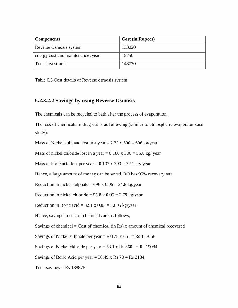
83
Components Cost (in Rupees)
Reverse Osmosis system 133020
energy cost and maintenance /year 15750
Total Investment 148770
Table 6.3 Cost details of Reverse osmosis system
6.2.3.2.2 Savings by using Reverse Osmosis
The chemicals can be recycled to bath after the process of evaporation.
The loss of chemicals in drag out is as following (similar to atmospheric evaporator case
study):
Mass of Nickel sulphate lost in a year = 2.32 x 300 = 696 kg/year
Mass of nickel chloride lost in a year = 0.186 x 300 = 55.8 kg/ year
Mass of boric acid lost per year = 0.107 x 300 = 32.1 kg/ year
Hence, a large amount of money can be saved. RO has 95% recovery rate
Reduction in nickel sulphate = 696 x 0.05 = 34.8 kg/year
Reduction in nickel chloride = 55.8 x 0.05 = 2.79 kg/year
Reduction in Boric acid = 32.1 x 0.05 = 1.605 kg/year
Hence, savings in cost of chemicals are as follows,
Savings of chemical = Cost of chemical (in Rs) x amount of chemical recovered
Savings of Nickel sulphate per year = Rs178 x 661 = Rs 117658
Savings of Nickel chloride per year = 53.1 x Rs 360 = Rs 19084
Savings of Boric Acid per year = 30.49 x Rs 70 = Rs 2134
Total savings = Rs 138876

84
6.2.3.3.3 Payback period of Reverse Osmosis
Amount saved per day from savings (assuming 300 working days) = 138876/300
= Rs 463
Payback period for the equipment cost = 133020/463 = 287.3 days ~ 287 days
= 11.4 months (300 working days)
Thus, payback period is 11.4 months (assuming 300 working days).
The cost of electricity per year = Rs 15750
After the payback period of approximately 1 year, the plating unit will be able to
compensate the electricity cost of 2 years and afterwards, will be able to save money as =
138876 –(2 x 15750) = Rs 107376
In 3rd
year the total savings will be = (107376 + 138876) – 15750 = Rs 230502
The amount saved at the end of 3rd
year will be enough for the replacement of membrane
and for the treatment of permeate water having concentration 102.5 mg/l and flow rate as
152 l/day.
Savings per year = Rs (138876 – 15750) = Rs 123126.
Thus, both economically and from environmental point of view, RO technique proved to
be useful for the above case study.
6.2.3.3 Disadvantages of RO system
a) RO operates in pH range of 2-11, so highly acidic or highly basic in nature
chemicals cannot be recovered.
b) RO is incapable of concentrating solutions to very high concentrations. Thus, a
small evaporator is required to close the loop.
c) Certain species which are small non-ionized molecules (Sodium, brightener) are
not completely rejected.
d) Membrane performance generally degrades with time requiring periodic
replacement of membrane.
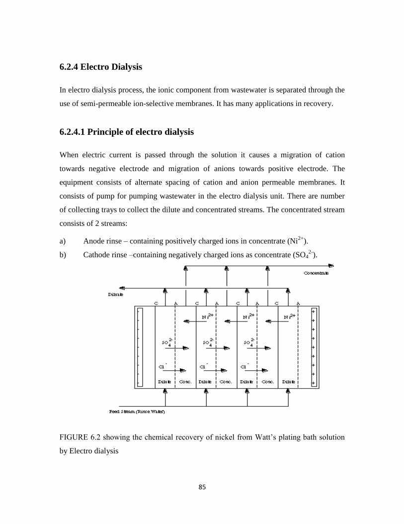
85
6.2.4 Electro Dialysis
In electro dialysis process, the ionic component from wastewater is separated through the
use of semi-permeable ion-selective membranes. It has many applications in recovery.
6.2.4.1 Principle of electro dialysis
When electric current is passed through the solution it causes a migration of cation
towards negative electrode and migration of anions towards positive electrode. The
equipment consists of alternate spacing of cation and anion permeable membranes. It
consists of pump for pumping wastewater in the electro dialysis unit. There are number
of collecting trays to collect the dilute and concentrated streams. The concentrated stream
consists of 2 streams:
a) Anode rinse – containing positively charged ions in concentrate (Ni2+
).
b) Cathode rinse –containing negatively charged ions as concentrate (SO42-
).
FIGURE 6.2 showing the chemical recovery of nickel from Watt’s plating bath solution
by Electro dialysis

86
(Source: Pollution prevention and control technologies for plating operations, National
metal finishing Resource centre)
Wastewater is pumped in electro dialysis cells as shown in figure 2. When electric
current is passed through the wastewater, the formation of cations (Ni2+
) and anions
(SO42-
) takes place which migrates to cathode and anode respectively. The ions get
separated by cation and anion selective permeable membranes. This causes the formation
of 3 streams:
a) Cathode stream
b) Anode stream
c) Dilute stream – containing water
The 3 streams are collected in different trays, which can be recycles to plating bath.
6.2.4.2 Factors affecting Electro dialysis
However, the removal of salts depends on following factors:
i. Amount of electricity passed through the solution
ii. Type and amount of ions
iii. Temperature of wastewater
iv. Selectivity of membrane
v. Flow rate of wastewater
6.2.4.3 Case study of Electro dialysis
The chemical recovery from electro dialysis will be depicted by taking a case study from
a plating unit, performing nickel plating in Moradabad.
The wastewater coming out after 2 stage counter current rinsing operation has
concentration 1025 mg/l and flow rate is 160 l/ day (values taken from Chapter-5)
The current required for electro dialysis can be estimated using Faraday’s laws of electro
dialysis. The number of gram equivalents removed per unit time is given by:
Gram eq/ unit time =QNy ----------------- (17)
87
Where, Q = flow rate in litres/second
N = normality of solution, eq/l
y = electrolyte removal as a fraction
The corresponding expression for current for a stack of membranes is given by:
I = FQNy ------------------ (18)
nEC
Where, I = current in Ampere
F = faraday’s constant, 96485 A.s/eq
n = number of cells in a stack
EC = current efficiency expressed as a fraction
(Source: Metcalf and Eddy)
Cation and anion concentration = 0.96 g-eq/l
Now, efficiency of salt removal of electro dialysis = 50%
The current efficiency = 90%
Resistance = 7 ohms
No. of cells in stack (n) = 25
6.2.4.3.1 Cost of Electro dialysis
Calculating the current required using equation (18)
I = 96485 x 160 x 0.96 x 0.5
25 x 0.90 x 8 x 3600
I = 11.43 A
Determining the power (P) required
P = R (I)2
P = 7 x (11.43)2

88
P = 914.5 W = 0.914 kW
Power requirement for a year = 0.914 x 8 x 300 = 2194 units
Energy cost =2194 x Rs 4.65 = Rs 10202
Components Cost (in Rupees)
Electro dialysis system 354720
energy cost and maintenance /year 10202
Total Investment 364922
Table 6.4 Cost details of Electro-dialysis system
6.2.4.3.2 Savings by using electro dialysis
The drag-out losses are as follows:
Mass of Nickel sulphate lost in a year = 2.32 x 300 = 696 kg/year
Mass of nickel chloride lost in a year = 0.186 x 300 = 55.8 kg/ year
Mass of boric acid lost per year = 0.107 x 300 = 32.1 kg/ year
The salt removal efficiency of electro dialysis equipment is 50%
Savings of Nickel sulphate per year = Rs178 x 348 = Rs 61944
Savings of Nickel chloride per year = Rs 360 x 27.9 = Rs 10044
Savings of Boric Acid per year = Rs 70 x 16.05 = Rs 1123.5
Total savings per year = Rs 73111
6.2.4.3.3 Payback period of Electro dialysis equipment
Amount saved per day from savings (assuming 300 working days) = 73111/300
= Rs 244
Payback period for the equipment cost = 354720/244 = 1453.7 days ~ 1454 days
= 58.16 months (300 working days)
Thus, payback period is 58 months (assuming 300 working days). Thus it will be
approximately equivalent to 4 years and 10 months.
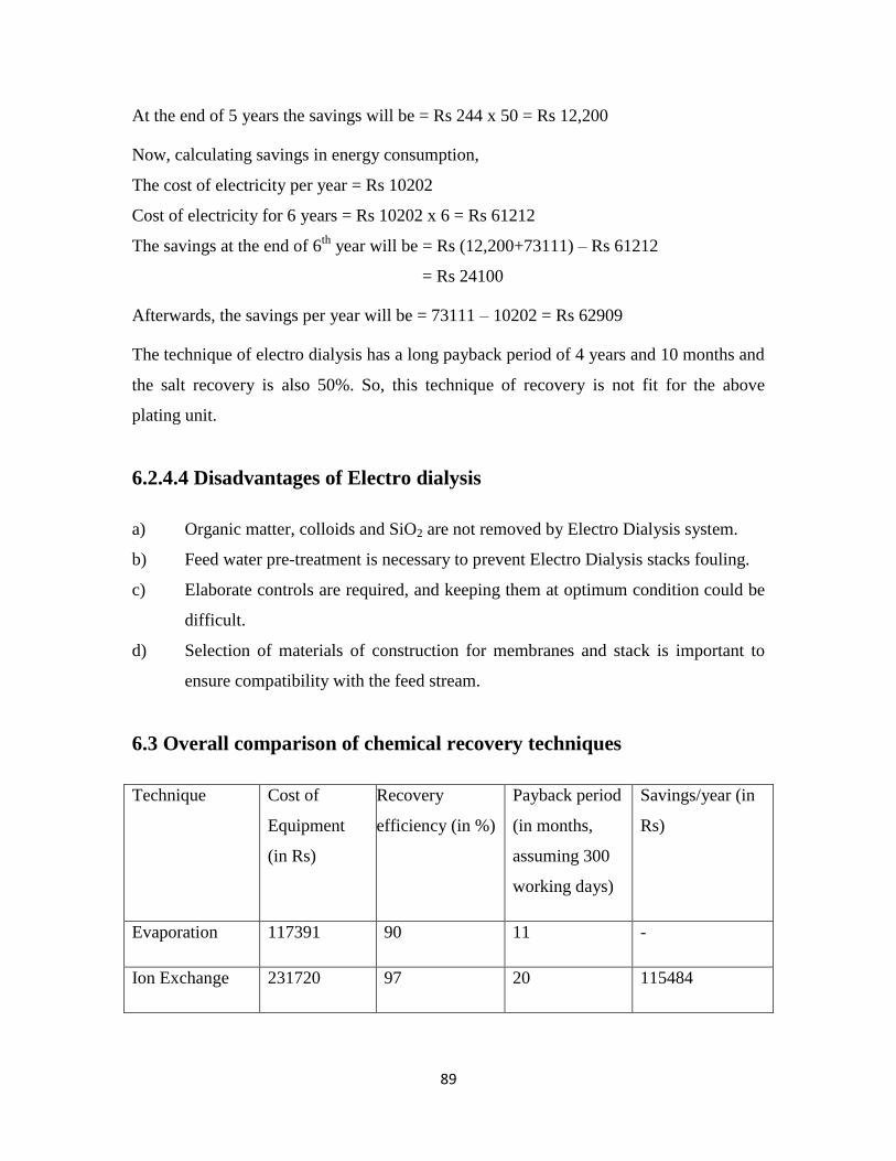
89
At the end of 5 years the savings will be = Rs 244 x 50 = Rs 12,200
Now, calculating savings in energy consumption,
The cost of electricity per year = Rs 10202
Cost of electricity for 6 years = Rs 10202 x 6 = Rs 61212
The savings at the end of 6th
year will be = Rs (12,200+73111) – Rs 61212
= Rs 24100
Afterwards, the savings per year will be = 73111 – 10202 = Rs 62909
The technique of electro dialysis has a long payback period of 4 years and 10 months and
the salt recovery is also 50%. So, this technique of recovery is not fit for the above
plating unit.
6.2.4.4 Disadvantages of Electro dialysis
a) Organic matter, colloids and SiO2 are not removed by Electro Dialysis system.
b) Feed water pre-treatment is necessary to prevent Electro Dialysis stacks fouling.
c) Elaborate controls are required, and keeping them at optimum condition could be
difficult.
d) Selection of materials of construction for membranes and stack is important to
ensure compatibility with the feed stream.
6.3 Overall comparison of chemical recovery techniques
Technique Cost of
Equipment
(in Rs)
Recovery
efficiency (in %)
Payback period
(in months,
assuming 300
working days)
Savings/year (in
Rs)
Evaporation 117391 90 11 -
Ion Exchange 231720 97 20 115484

90
Reverse
Osmosis
133020 95 12 123126
Electro Dialysis 354720 50 58 62909
Table 6.5 Comparison of different techniques of chemical/metal recovery with respect to
efficiency and payback period.
It was found from the case study done at Moradabad, that evaporation technique is not
feasible due to high operating costs (electricity charges were more than savings per year)
Though the cost of the machine is least, but the operating cost (electricity charges Rs145824 per
year) is quite high as compared to other techniques (RO and Electro dialysis). Thus, in totality the
running cost of equipment is less than the savings done by the equipment. Therefore, the
expenditure or amount of money used in operation will be always on the higher side for the above
discussed plating unit.
Suitable condition for the use of evaporator
The technique may be suitable for recovery of metals/ chemicals which are expensive (e.g. Gold,
Silver etc).
The comparative data from Table 6.5 indicated that payback period of electro dialysis is quite
long (4 years, 10 months), and recovery of salt is also 50% also. Thus, this technique may prove
costlier and wastewater still requires effluent treatment.
The performance of ion exchange and RO system was found to be similar, with respect to savings
per annum (ion exchange – Rs 115484, RO – Rs 123126) and efficiency ( Ion exchange- 97%,
RO- 95%). The payback period of RO system (12 months) is significantly less than Ion exchange
(20 months), but, the drawbacks of RO system were its incapability to concentrate wastewater to
high concentrated chemicals (needs evaporation).
Also, the use of RO system was restricted to pH range of 2-11 only. Therefore, it can be
concluded that the ion exchange method is superior to other techniques of chemical recovery,
which was established by the given case study done at Moradabad

91
Table 6.6 Types of plating and suitable technique for recovery of metal
Methods/
Techniques
Cyanide
Silver
plating
Acid
Copper
Plating
Nickel
Plating
Decorative
Chrome
Plating
Hard
Chromium
Plating
Cyanide
Zinc
Plating
Cadmium
Plating
Copper
Plating
Ion-
Exchange*
Yes Yes Yes Yes Yes
Reverse
Osmosis
Yes Yes Yes Yes Yes
Electro-
Dialysis*
Yes Yes Yes
Evaporation* Yes Yes Yes Yes Yes
Typical
Recovery
Efficiency
>99% 80-
90%
98% 98% 95% 70% 70% 98%
*Source: UNEP: “Environmental Aspects of Metal Finishing Industry, A Technical
Guide, “Paris, 1993
92
Chapter 7
Summary and Conclusion
In the study, survey was done in organized sector of Electroplating Industry in
Moradabad (U.P.). The main focus of project centers on the electroplating industry and
its environmental concerns.
The electroplaters are found in entire country with significant proportion in Punjab,
Haryana and U.P. so, Moradabad was selected as the study area, having variety of
electroplaters in both organized as well as unorganized sector. So, therefore, with the help
of a case study an attempt was made to investigate the feasibility of introducing waste
minimization and chemical recovery techniques.
The report gives the idea about the typical chemicals used in different metal plating with
their environmental concerns.
Waste minimization encompasses the techniques to minimize the resources viz. counter-
current and spray rinsing techniques. Reduction of resources (water for rinsing) was
illustrated with the help of case study (done at Moradabad). The reduction in water for
rinsing will directly reduce the toxic metal/hazardous waste discharged into the water
bodies
By using 2 stage counter-current rinsing it was found that the consumption of rinse water
reduced from 2250 l/day to 160 l /day, which is almost 93% reduction in the consumption
of rinse water. The spray rinsing technique reduces the water consumption from
2250l/day to 282 l/day. This is a remarkable achievement both in terms of environmental
and economic point of view.
On comparison, it was found that counter current system not only reduces the
consumption of water more effectively than spray rinsing but, also operating and
maintenance cost is cheaper than spray rinsing in given case study. Thus, counter current
technique should be used instead of spray rinsing for the above mentioned electroplating
unit.

93
Waste minimization procedure is followed by chemical recovery. Chemicals are present
in wastewater after rinsing as drag out losses. There are many techniques for chemical
recovery in electroplating. In this project work, only 4 techniques were discussed in detail
namely, Evaporation, Ion-exchange, Reverse osmosis and Electro dialysis. The
comparative study table has been done in Chapter 6 (refer Table 6.5)
It was found from the case study done at Moradabad, that evaporation technique was not
feasible for the given unit, due to high operating costs (electricity charges were more than
savings per year). The technique of Ion exchange was found to be the most feasible
technique for chemical recovery, with minimum waste generation and optimized
chemical recovery as compared to the other techniques (RO, Evaporation and Electro
dialysis).
According to the COINDS, CPCB have also conducted studies on chemical recovery. On
comparing the results of the given study, and COINDS, it was found that Ion exchange is
the most appropriate technique for chemical recovery.
The results are formed on theoretical calculations from the data obtained from the plating
unit in Moradabad. The actual performance of all the equipments will have to be
determined from pilot tests. In practice, due to leakage and other operational and design
limitations, the required volume of resin in ion exchange will be usually higher than
computed exchange capacity.
The project report lacks the energy conservation in the industry, which could not be
performed due to project constraints.

94
REFERENCES Aval and Motedayan (1991). Removal of Pb, Cu ions from waste water by Saw
dust, Iran J. Chem. 10 (1991), pp. 21–23
Dabrowski A., Hubicki Z., Podkoscielny P. and Robens E., (2004), Chemosphere, 56,
91–106
Ajmal M., Sulaiman A. M. and Khan A. H., (1993). “Surface Entrapment of toxic
metals from electroplating waste and their possible recovery”. Water Air soil Pollution,
68, 485 92.
Begum Shakila (1992), Determination of copper in industrial effluents and receiving
water and its removal by adsorption on saw-dust, Science International. 4 (1992), pp. 67–
68
C. Kamizawa, H. Masuda, M. Matsuda, T. Nakane and H.Akami (1978). “Studies on
the treatment of gold plating rinse by reverse osmosis, Desalination”. 27, 261
Carmen P. Gomes, Manuel F. Almeida and Jose M. Loureiro (1999), Gold recovery
with ion exchange used resins. Laboratory of Separation and Reaction Engineering,
University of Porto, Rua dos Bragas, 4050-123, Porto, Portugal
Duke L. D. (1994). “Hazardous waste minimization: is it taking root in U.S. industry”?
Waste minimization in metal finishing facilities of the San Francisco Bay Area,
California. Waste Management, 14, 49-59.
EPA, (1982). “Environmental pollution control alternative: Sludge handling, dewatering,
and disposal alternatives for the metal finishing industry”. U.S. EPA, October
Freeman H. M. (1988). “Waste minimization audit report: Case studies of minimization
of cyanide waste from electroplating operation”. EPA/600/$2-87/056, EPA, pp. 24-62.
Golomb A. (1972), Application of reverse osmosis to electroplating waste
treatment, Plating 59 (1972), p. 316.
Higgins, T. (1989). “Hazardous Waste Minimization”. Chap. 1. Lewis,Chelsea, MI
Howard S. Hartley, PE, (January, 1982). “The Evolution of evaporative recovery
(Several factors have led to downsized systems and enhanced the economic benefits of
recovery.)”. PLATING AND SURFACE FINISHING.

95
Huang and Luo (1997). “Intelligent Decision Support for Waste Minimization in
Electroplating Plants”. Wayne State University, Detroit, MI, U.S.A
Huang C. P. and Wu M. H. (1977). “The removal of chromium (VI) from dilute
aqueous solution by activated carbon”. Wat. Res. 11, 673-679
Huang Y. L., Sundar G. and Fan L. T. (1991). “MIN-CYANIDE: an expert system for
cyanide waste minimization in electroplating plants”. Environmental Progress, 10, 89-95.
Keukeleire and Nascimento (2010). “Green coconut shells applied as adsorbent for
removal of toxic metal ions using fixed-bed column technology”. Department of Hydraulic
and Environmental Engineering, Federal University of Ceará - UFC, Fortaleza, CE, Brazil.
Kimbrough D.E., Cohen Y., Winer A. M., Creelmen L. and Mabuni C., (1999). “A
critical assessment of chromium in the environment”. Crit. Rev. Environ. Sci.
Technol. 29 (1)
Koga S. and Ushikoshi K. (1977). “ALCLOSE reverse osmosis system, Desalination”.
23- 105
Kremen S.S., Hayes C. and Dubos M. (1977), “Large-scale reverse osmosis processing
of metal finishing rinse water, Desalination”. 20-71
Kushner, J. B. and Kushner A.S. (1981). "Water and Waste Control For the Plating
Shop." Second Edition. Gardner Publications. Cincinnati, Ohio.
Martin Goosey Martin and Rod Kellner, December 2009. Energy demand and conservation/
Management within surface engineering and allied sectors, A BEST PRACTICE GUIDE by
Env-Aqua Solutions Ltd
Meltzer M., Callahan M. and Jensen T. (1990). “Metal-Bearing Waste Streams:
Minimizing, Recycling, and Treatment”. Noyes, Park Ridge, NJ

96
Mohler J. B., (1973). "The Art and Science of Rinsing." American Electroplating
Society. Winter Park, Florida.
Noyes R. (1993). “Pollution Prevention Technology Handbook, Chap. 28”. Noyes, Park
Ridge,NJ
Rittmeyer R. W. (1991). “Prepare an effective pollution prevention program.” Chemical
Engineering Progress, 87, 56-62
Sato T., lmaizumi M., Kato O. and Taniguchi Y. (1977). “RO applications in
wastewater reclamation for re-use, Desalination”. 23-65.
Stoecker B.J. (1999). “Chromium absorption, safety and toxicity”. J. Trace Elem. Exp.
Med. 12 (2) pp. 163–169.
W. Fries and D. Chew, (1993), Get the metal out, Chemtech 23 (2), pp. 32–35
William J. McLay, January 28, 1998, “Fundamentals of evaporation and evaporators
for plating bath and rinse water recovery in the surface finishing industry”. Process
Engineering De Dietrich Process Systems, Inc
Bibliography
Comprehensive Industry Document on Electroplating Industries (Coinds), May,
2007, Central Pollution Control Board, Ministry of Environment and Forests
International Metalworker’s Federation, Metal Industry in India – A Survey,
October, 2002, A Survey of Characteristics of the Metal Industry, its Structure and Trade
Unions in India.
IMF-LO/FTF Organizing Project in India
John Pichtel, 2005, Waste Management practices-Municipal, Hazardous, and Industrial
97
Metcalf and eddy, Wastewater Engineering, treatment and reuse, fourth edition, Tata Mc
Graw Hill edition)
Mohler, J. B., (1982). "Water Rinsing". In: Metal Finishing Guidebook and Directory
Issue: '82. Metal Finishing. Hackenrack, New Jersey. Pages 498-510.