industrial electroplating
DESCRIPTION
consolidate plating types used in industriesTRANSCRIPT
Comprehensive Industry Document Series (COINDS)
COINDS /70/2007
COMPREHENSIVE INDUSTRYDOCUMENT ON
ELECTROPLATINGINDUSTRIES
OF CLEAN
CENTRAL POLLUTION CONTROL BOARDMINISTRY OF ENVIRONMENT & FORESTSWebsite: www.cpcb.nic.in e-mail: [email protected]
MAY 2007

Comprehensive Industry Documents Series (COINDS)
COINDS /70/2007
COMPREHENSIVE INDUSTRYDOCUMENT ON
ELECTROPLATINGINDUSTRIES
CENTRAL POLLUTION CONTROL BOARDMINISTRY OF ENVIRONMENT & FORESTS
e-mail: [email protected] Website: www.cpcb.nic.in
May 2007
CPCB, 200 Copies, 2007
Published By : Dr. B. Sengupta, Member Secretary, Central Pollution Control Board, Delhi — 32Printing Supervision & Layout: P.K. Mahendru, and Anamika SagarComposing & Laser Typesetting : Suresh Chander SharmaPrinted at: DSIDC, New Dellhi:

vim. . ITF\S ct , ziTA.Zi.31~
J. M. MAUSKAR, IAsChairman
= zi ASXTDT f5IUT •^3`(-ff t fzThN Zfij z1Tr9)
uuicN u ► Lu tI-f reerL7
Central Pollution Control Board(A Govt. of India Organisation)
Ministry of Environment & Forests
Phone 22304948/22307233
FOREWORD
The Central Pollution Control Board (CPCB) brings out publicationsentitled "Compr::hensive Industry Document series (COINDS)" based onthe industry-wise studies. These reports are intended to cover variousaspects of different types of industrial units in the country with respect totheir number, locations, capacities, types of product, usage of rawmaterials, process adopted, waste minimisation, pollution prevention andcontrol measures. The Minimal National Standards (MINAS) have beenevolved as a result of the COINDS. The present report entitled"Comprehensive Industry Document on Electroplating Industries" is latestone being published by the CPCB.
The study for the report was conducted on behalf of the CPCB by ENCConsulting Engineers, Gurgaon. The help and assistance extended by theState Pollution Control Boards and by various electroplating units duringthe conduct of this study are gratefully acknowledged. Shri T Venugopal,Director, Shri R. C. Saxena, SEE and Ms. L.J. Pavithra AEE, has put keenefforts in preparing this volume under the able guidance of Dr. B.Sengupta, Member Secretary.
I hope that this report would be useful to the electroplating units, regulatoryagencies, consultants and others interested in pollution control in thissector.
(J. M. Manskar)May, 2007
'Parivesh Bhawan C.B.D.-cum-Office Complex, East Arun Nagar, Delhi-t 10 032Fax : 22304948 t 22307078 email : [email protected]
Website : http://www.cpcb.nic in

Contents
Chapter 1: Introduction I1. I Introduction 11.1 Growth of Electroplating in India I1.2 Types and Location of Units 21.3 Future Potential 2
Chapter 2: Processes and Chemicals used2. I Production Process 52.2 Process Details 62.3 Process Chemicals 82.4 Some Theoritical Considerations in Electroplating 102.5 Mass Balance for Plating Process 17
Chapter 3 In-depth Studies in Electroplating Industry 273.1 General 273.2 Analysis of Results 273.3 Summary of Findings 37
Chapter 4 Recovery of Metals4.1 General 394.2 Filtration and Centrifugation 394.3 Evaporation 404.4 Electrolytic Recovery and its Economics 424.5 Reverse Osmosis 47
Chapter 5 Waste Minimisation and treatment to Control Pollution5.1 General 495.2 Waste Minimisation and Process Modification 495.3 Best Available Technology (BAT) 515.4 Specific BAT Approach 555.5 potential Initiatives and Cost Estimates 595.6 Waste Treatment Options 605.7 Hazardous Waste Rules 665.8 House Keeping Guidelines 67
Chapter 6 Review of Existing Standards6.1 General 71
6.2 Suggested Revisions in Existing Standards 71
6.3 Recommendation for Monitoring of Revised Standard 78
6.4 Safe Keeping of Data 79

Chapter I
Introduction
1.1 Introduction
Electroplating is one of the varieties of several techniques of Metal Finishing. It is utechnique of deposition of' a fine layer of one metal on another through elcctroI\ ticprocess to impart various properties and attributes, such as corrosion protection,enhanced surface hardness, lustre, colour, aesthetics, value addition etc. I:Icctroplatinoperations form part, of large scale manufacturing plants (e.g. automobile. cycle.engineering and numerous other industries) or performed as job-work by small and tinyunits. They are spread across the entire country with significant concentration in severalstates like Punjab. Haryana, part of U.P., Maharashtra, Karnataka,Andhra Pradesh, TamilNadu and West Bengal. Electroplating is considered a major polluting industry because itdischarges toxic materials and heavy metals through wastewater (effluents), air emissionsand solid wastes into the recipient environment.
In order to regulate the quality of discharge of wastewater, the Central Pollution ControlBoard. in 1987, evolved Minimal National Standard (MINAS) flor discharge of effluentunder the provision of the Environment (Protection) Act of 1986. This standard no\\requires comprehensive review in view of the current body of' knowledge regardingdischarge of pollutants, status of Industry, technology and implementation of regulatorymechanism.
1.2 Growth of Electroplating in India
1.2.1 Brief History & Present Scenario
Electroplating has a long history in India; like many industrial activities, it gainedmomentum after Independence. Modern day electroplating started in early sixties inMumbai with dull Nickel. Bright Nickel followed soon after. Although official figuresare not available, estimates (ref: 5) indicate that in 1970, electroplating industry wasconsidered to be in the tune of Rs. 100 million. Since then, the industry has grownsteadily without facing any recession. In 1976, the first semi-automatic plant was set upin Mumbai. Currently there are more than 600 automatic plants in the country. During theperiod 1970-85, the import restriction regulation in force led to high growth of thisindustry. It is estimated that electroplating industry is now worth Rs. I000 crores (Rs.10,000 million; see Fig 1.1). This means that compounded average annual growth rate isabout 16.6%. The sector employs about 1,30,000 people in approximately 12,000organized units. No statistics is available for unorganized 'units.

1.2.2 Types and Location of UnitsThe Industry is widely spread out across the country. While there are primarily twovarieties- (i) Primary User and Original Equipment (OE) manufacturer, who doelectroplating as one of their overall manufacturing activity and (ii) Job work units, whodo only plating for a large variety of components for both domestic and export purpose.Certain states have large number of units concentrated in some towns / cities, such asAndhra Pradesh -- HyderabadDelhiGujarat- AhmedabadHaryana- FaridabadKarnataka- BangaloreMaharashtra - Mumbai, Pune, NashikPunjab - LudhianaTamil Nadu - Chennai, MaduraiUttar Pradesh - NOIDA
It is difficult to find out the distribution of production between the organized and smallscale / tiny / unorganized sector. However, judging by the consumption of chemicals andadditives, it is estimated that about 18,000 tons are consumed by organized sector, whiletiny and unorganized sector consumes about 10,000 tons. Therefore, approximately 36 %of the industry is contributed by the unorganized sector.
R

Fig : 1.1 Growth of Electroplating Industry in India
Fig. 1.2 : Share of Chemicals as inputs to electroplating
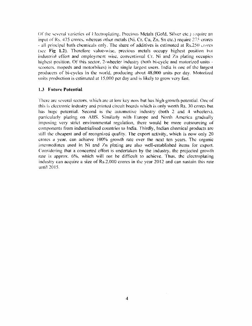
Ut' the several varieties of Flectroplatine. Precious Metals (Gold, Silver etc.) rcquirc aninput of Rs. 475 crores, whereas other metals (Ni, Cr. Cu, Zn, Sn etc.) require 27. crores- all principal bath chemicals only. The share of additives is estimated at Rs.250 .:rores(see Fig 1.2). Therefore value-wise, precious metals occupy highest position Nutindustrial eflbrt and employment wise, conventional Cr. Ni and In plating occupieshighest position. Of this sector. 2-wheeler industry (both hi-cycle and motorized units -scooters. mopeds and motorbikes) is the single largest users. India is one of the largestproducers of bi-cycles in the world, producing about 48,000 units per day. Motorizedunits production is estimated at 15,000 per day and is likely to grow very fast.
1.3 Future Potential
I hcrc are several sectors. which are at low key now but has high growth potential. One ofthis is electronic Industry and printed circuit hoards which is only worth Rs. 30 crores buthas huge potential. Second is the automotive industry (both 2 and 4 wheelers),particularly plating on ABS. Similarly with Europe and North America graduallyimposing very strict environmental regulation, there would be more outsourcing ofcomponents from industrialised countries to India. Thirdly, Indian chemical products arestill the cheapest and of recognized quality. The export activity, which is now only 20crores a year, can achieve 100% growth rate over the next ten years. The organicintermediates used in Ni and Zn plating are also well-established items for export.Considering that a concerted effort is undertaken by the industry, the projected growthrate is approx. 6%, which will not be difficult to achieve. Thus, the electroplatingindustry can acquire a size of Rs.2,000 crores in the year 2012 and can sustain this rateuntil 2015.
4
Chapter 2
Processes & Chemicals Used
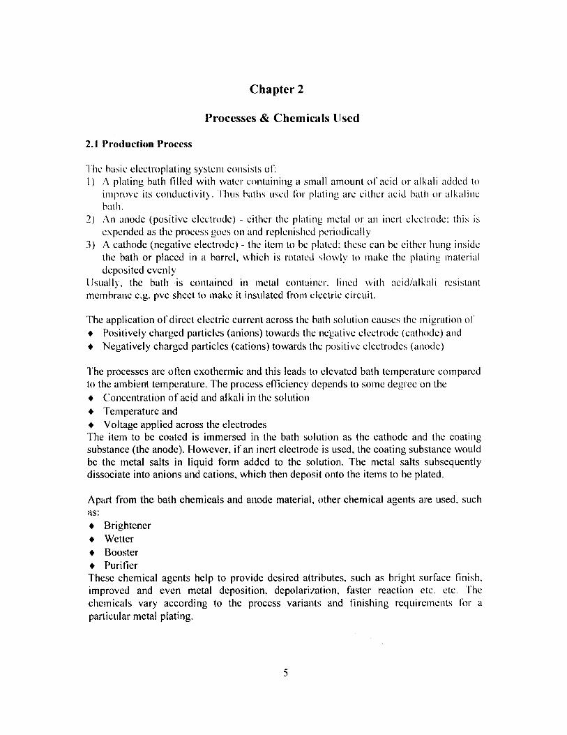
2.1 Production Process
The basic electroplating system consists of:I) A plating bath tilled with water containing a small amount of acid or alkali added to
improve its conductivity. Thus baths used lor plating are either acid bath or alkalinebath.
2) An anode (positive electrode) - either the plating metal or an inert electrode: this isexpended as the process goes on and replenished periodically
3) A cathode (negative electrode) - the item to be plated: these can he either hung insidethe bath or placed in a barrel, which is rotated slowly to make the plating materialdeposited evenly
Usually, the bath is contained in metal container, lined with acid/alkali resistantmembrane e.g. pvc sheet to make it insulated trom electric circuit.
The application of direct electric current across the bath solution causes the migration of• Positively charged particles (anions) towards the negative electrode (cathode) and• Negatively charged particles (cations) towards the positive electrodes (anode)
The processes are often exothermic and this leads to elevated bath temperature comparedto the ambient temperature. The process efficiency depends to some degree on the• Concentration of acid and alkali in the solution• "Temperature and• Voltage applied across the electrodesThe item to be coated is immersed in the bath solution as the cathode and the coatingsubstance (the anode). However, if an inert electrode is used, the coating substance wouldbe the metal salts in liquid form added to the solution. The metal salts subsequentlydissociate into anions and cations, which then deposit onto the items to be plated.
Apart from the bath chemicals and anode material, other chemical agents are used, suchas:• Brightener• Wetter• Booster• PurifierThese chemical agents help to provide desired attributes, such as bright surface finish,improved and even metal deposition, depolarization, faster reaction etc. etc. Thechemicals vary according to the process variants and finishing requirements fr aparticular metal plating.
E
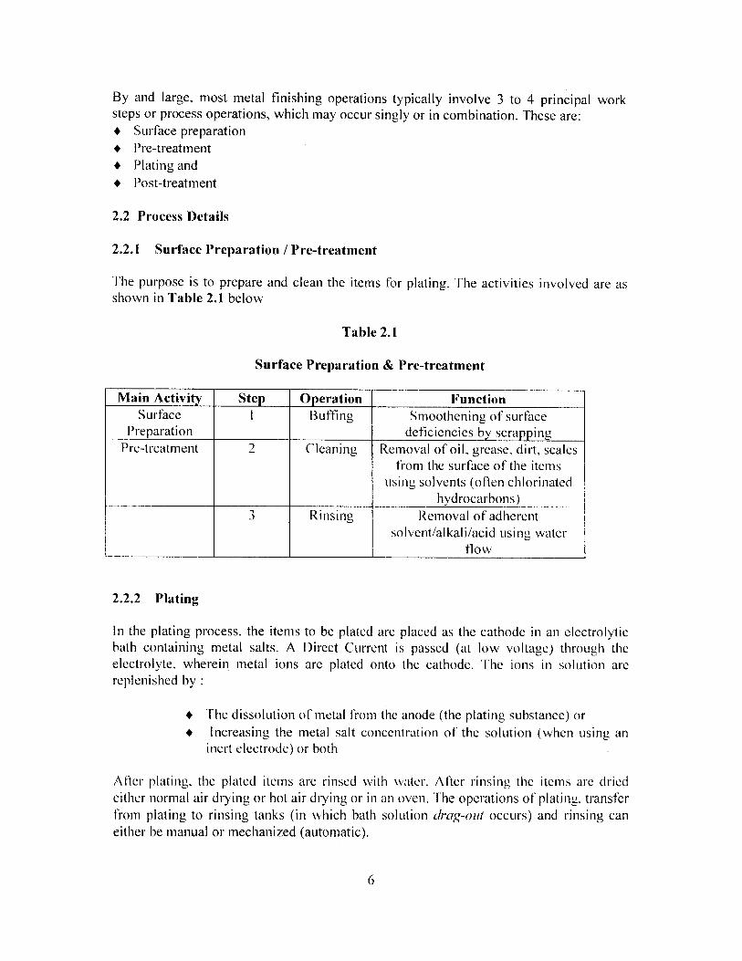
By and large, most metal finishing operations typically involve 3 to 4 principal worksteps or process operations, which may occur singly or in combination. These are:• Surface preparation• Pre-treatment• Plating and• Post-treatment
2.2 Process Details
2.2.1 Surface Preparation / Pre-treatment
The purpose is to prepare and clean the items for plating. The activities involved are asshown in Table 2.1 below
Table 2.1
Surface Preparation & Pre-treatment
Main Activity Step Operation FunctionSurface I Buffing Smoothening of surface
Preparation deficiencies bv scrappingPre-treatment 2 Cleaning Removal of oil, grease. dirt, scales
from the surface of the itemsusing solvents (often chlorinated
hydrocarbons)3 Rinsing Removal of adherent
solvent/alkali/acid using waterflow
2.2.2 Plating
In the plating process, the items to be plated are placed as the cathode in an electrolyticbath containing metal salts. A Direct Current is passed (at low voltage) through theelectrolyte, wherein metal ions are plated onto the cathode. The ions in solution arereplenished by :
• The dissolution of metal from the anode (the plating substance) or• Increasing the metal salt concentration of the solution (when using an
inert electrode) or both
After plating, the plated items are rinsed with water. After rinsing the items are driedeither normal air drying or hot air drying or in an oven. The operations of plating. transferfrom plating to rinsing tanks (in which bath solution drag-out occurs) and rinsing caneither be manual or mechanized (automatic).
6
2.2.3 Post-treatment
Most F,lectroplating operations are completed by the plating operation, if the items do notrequire post-treatment (as in the case of Double Nickel Chrome Plating). The purpose ofthe post-treatment is:
♦ to enhance the physical appearance of the item• to improve the corrosion resistance of the item• for decorative purposes
There are a varied number of post-treatments:• conversion coatings• chromating• phosphating• passivating• metal colouring and• sealing
A brief description of these are given in the following paragraphs
(a) Conversion Coating:Conversion coating is provided to prevent corrosion and to limit the growth of salts,which may form due to corrosion. Many heavy metals, such as Chromium,Vanadium, Molybdenum and Tungsten in their high valence states have the ability toprevent such corrosion. The most commonly used conversion coating is hexavalentchromium using soluble chromate salt such as Potassium di-chromate, calledchromate conversion coating or chromating.
(b) PhosphatingThis is a process of coating a metal surface (usually galvanized iron & steel,aluminium etc.) with a layer of insoluble metal phosphates by treating it with anacidic phosphate containing solution. Zinc, iron and manganese phosphate coatingsare common of which Zinc Phosphate is the most commonly used salt. Phosphating isdone as an excellent base for receiving paints, oils and cold-forming lubricants
(c) SealingAnodic coatings are usually porous and are sealed and are sealed to improve colourdurability and resistance to staining and corrosion. Sealing is done by immersion inhot water during which amorphous alumina surface of the anodic coating is convertedto crystalline alpha alumina hydrate, which increases the volume and closes the pores.
(d) Metal ColouringIn this process a colour is formed on the surface of metals. This is quite an oldprocess, which is not much used at present. However, Aluminium colouring is invogue.
7

2.3 Process Chemicals
A wide variety of chemicals and substances are used, depending upon the surfaceproperties of the objects to be electroplated, plating and finishing requirement as well asthe technology / facility offered by the platers. It is very difficult to provide full details ofall those used, because there are more than one commonly used process for certainmetals. I-fence a general description will be covered in this section. A summary is givenin Annexure 3.
2.3.1 Brass Plating
In brass plating, generally a cyanide bath is used, which comprises, Cu(CN) 2 NaCN,Zn(CN)2 and Na-, CO; . The anode is non-consuming conductor.
2.3.2 Bronze Plating
Bronze being a combination of Copper and Tin, the bath salts comprise Cu(CN)2 , NaCN,Na, SnO-, and NaOH. Bath is therefore cyanide alkaline. Anode is non-consumingconductor like in brass plating.
2.3.3 Cadmium Plating
Cadmium plating also uses an alkaline cyanide bath comprising bath salts like Cd(CN)2NaCN, Na-, CO3 and NaOH.
2.3.4 Chromium Plating
There are variations of Chromium plating - ordinary chrome, hard chrome and brightchrome. Generally, chromic acid bath is used comprising bath salts like 1-I 2 (' r 0. 1 , I I,SO,,and Nal'. NaF is used to improve the conductivity of the electrolyte.
2.3.5 Copper Plating
Three ") types of bath are used - (i) Cyanide Copper bath, (ii) Copper pyrophosphate bathand (iii) Acid Copper bath. As the name suggests, the bath in the third is acidic. while the.first two are alkaline. Bath constituents for Cyanide Copper bath are : Cu(CN), _ NaCN,Na, CO; and NaOH. For Copper pyrophosphate, Cu2P" 07, NIS.► OI-1 and K.iP2O7 areused. In acid copper process, a mix of CuSO. ► and 1-12SO.1 is used.
2.3.6 Gold Plating
Four processes are available - (i) Alkaline Cyanide f using KAu(CN)2, KCN, KON andK,C r O -I I. (ii) Neutral Gold bath fusing KAu(CN) 2 , KCI and K21-IP03 J, Acid Cyanidef using KAu(CN)2 , KCI and Citric Acids . It may be noted that the main constituent in all
8
three processes is Potassium Gold ('vanide. The l' urth is Mash Gold process using, AuCI ;
and I ICI.
2.3.7 Nickel Plating
Three"' processes are commonly used - (i) Watts Nickel bath I using a mix of NiSO.j .NiCl2, 11,SO. ► and l -I;BO; ], (ii) Nickel Sulphamate Bath [ using Ni(NI l SO,)2 , I-INI-1-,SO;], (iii) Wood's Nickel Bath ( using NiCI, and I lCl I. None of the processes use Cyanide.
2.3.8 Palladium
Being a precious metal, usage is somewhat restricted. Only one process using acid bath iscommonly used. Bath constituents are:Pd(.'12 , NIi.,CI and IICI. Sometimes Palladium-Nickel plating is used in which Palladium and Nickel is deposited in one bath. In thisprocess, bath constituents are: Pd(NH3)2(NO,)2, Nickel Sulpharnate and Nl-I40FI.
2.3.9 Platinum
Two processes are available : (i) Alkaline Platinum and (ii) Acid Platinum. In the former.H2PtCl e,. (NH;a )3PO 4 and NH. 4O(HI. In acid Platinum, bath constituents are: I l2l't(NO,.)2SO. 1
and 1-ISO.
2.3.10 Rhodium
Only one process using acid bath comprising Rhodium Sulphate and Sulphuric acid isused.
2.3.11 Silver
Two processes arc available, both using Silver Cyanide. Silver Cyanide bath comprisesKAg(CN)2 , KCN and K2CO3 Acid bath uses KAg(CN)2 Nael-IPO.j and II;PO. ► .
2.3.12 Tin
There are three processes - (i) Alkaline, (ii) Acidic and (iii) Fluoroborate.. In alkaline Tinprocess, principal chemical used are Sodium Stannate and Caustic Soda, 'f'in Sulphateuses Stannous Sulphate and Sulphuric Acid. In Tin Fluoroborate process, Chemicals usedare : Sn(BF4)2, HBF4, H3BO3and (IF.
2.3.13 Zinc
There are three processes available (i) Acid Cyanide. (ii) Alkaline Cyanide and (iii)Alkaline Cyanide Free. Acid Cyanide uses a bath comprising Zn(1 KC I. NI I. ► CI andI;BO; In Alkaline Cyanide, bath constituents are : ZnCN, NaCN. NaOI I and Na, ('O.
In the Alkaline Cyanide Free (ACI") process. bath chemicals arc rather simpler. /,nO andNaOI l. The latter is gaining popularity as a Cyanide free process.
9

2.3.14 Anodising
Anodising is mainly used as a pre-cleaning operation but sometimes used as a metalfinishing operation. In anodising, the object is made Anode, so that impurities and othermetals are removed. Sulphuric acid is mainly used as electrolyte in the bath.
2.3.15 Phosphating
Phosphating is carried out mostly as post treatment of plating. However, it is often usedas undercoat to receive paint on metal. .Bath constituents are Zinc-Calcium Phosphateand Na3PO4 .
2.3.16 Chromating
This is also a post treatment to plating. Bath constituents are Na 2CrO4 and Na2CO 3 .
2.3.17 Etching
This is used as a pre-treatment to plating and generally uses acidic bath Ferric Chlorideetchant (Ferric Chloride and HC1), Acid etchant ( mix of CuCl2_ 1-ICI and 1-120 2). InAmmoniacal etchant, a mix of Ammonium Chloride, Ammonium Hydroxide and SodiumHypochlorite) is used. A summary of chemicals is given in Table 3.2.
2.4 Some Theoretical Considerations in Electroplating
Electroplating is a complex chemical process and it is neither possible nor intended todeal with the theoretical aspects in this treatise. However, certain basic considerationsand introductions would help in understanding the processes and factors influencingthem. These would be dealt with briefly in this sub-section.
2.4.1 Calculation of coating, thickness, exposure time and current density
Faraday's laws form the basis of finding important values. Following are the parametersexpressed in units customary in electroplating:
Eei == Electrochemical equivalent, in g/ahF= Plated area in dm 2
1 = Current intensity, in ampi = Current intensity in amp/dm2
t = Exposure time in minutesTI = Current efficiency in %
d = Thickness of metal deposit, in microns (lt)
y = Density in g/cm 2
V = Volume of the deposited metalG = Weight of the deposited metal
ELIJ
Faraday's first law in the form G = Eel Q applies to a reaction which proceeds at 100%current efficiency. Because this is normally not the case, the current efficiency q must beintroduced into the equation. We obtain
G=Ee1Q1/100 (1)Introducing time in minutes and current density in amp/dm 2 we obtain
G= Ee l i Ftri / 6000 grams (2)The coating thickness d = V (cm 3 in t is then:
F (dm'`)d= 100V microns (µ)
(3)F
Substituting V = G , we obtain
Y
d= LOOG microns (pt) (4)
yFAccording to this formula, we obtain the coating thickness on the plated surface F fromthe deposited weight G.For G we can introduce Eq.(2) and obtain
d= 100 Eel ii Ftri (g)
(5)
6000VFor
d= Eel (µ)60 y F (6)
Using this equation, the current density required to obtain the desired coating thickness,in a given time t is:
i=60 d y (amp/dm') (7)
Eel tl
And the time required, for a given current density, is:t=60 d y (min)
(8)
Eel ill
If instead of the-coating thickness, the weight deposited is required, the formulaecorresponding to equations (7) and (8) are obtained from Eq. (2):
i =6000 G (amp/dm2) (9)Eel F tr1
Andt=6000 G (min) (10)
Eel F i 1^These formulae apply equally to cathodic deposition and anodic dissolution of metal.The value of Eel are given in Table 2.2.
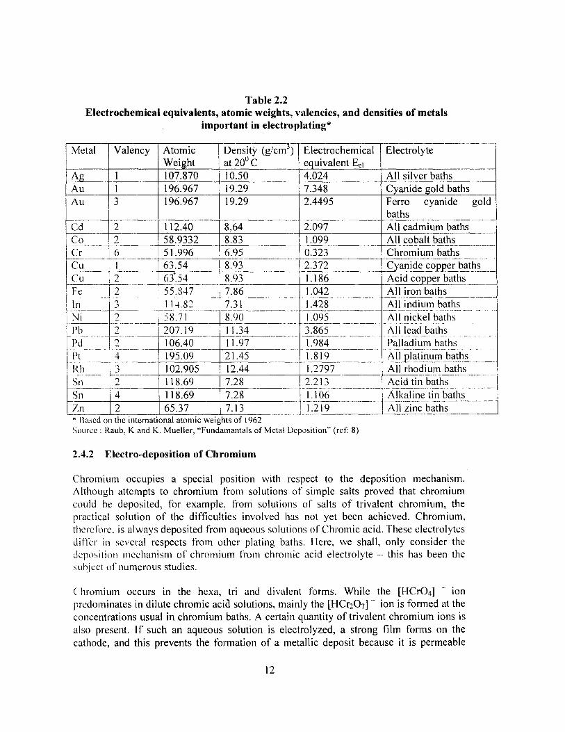
Table 2.2Electrochemical equivalents, atomic weights, valencies, and densities of metals
important in electroplating*
Metal Valency AtomicWeight
Density (g/c )at 200 C
Electrochemicalequivalent Eei
Electrolyte
Ag 1 107.870 10.50 4.024 All silver bathsAu 1 196.967 19.29 7.348 Cyanide gold baths _Au 3 196.967 19.29 2.4495 Ferro cyanide gold
baths Cd 2 112.40 8.64 2.097 All cadmium bathsCo 2 58.9332 8.83 1.099 All cobalt bathsCr 1 6 51.996 6.95 0.323 Chromium bathsCu !Cu
12
63.5463.54
8.938.93
2.3721.186
Cyanide copper bathsAcid copper baths
Fe 55.8473 114.822 58.712 207.19
7.86 1.042 All iron bathsIn 7.31
8.9011.34
1.4281.0953.865
All indium bathsAll nickel bathsAll lead bathsPalladium bathsAll platinum baths
N iPbPdPtRh
j 2 106.40 11.97 1.9841.8191.2797- -
43
195.09102.905
21.4512.44 All rhodium baths-- - - ----------
Sin 2 118.69 7.28 2.2131.106------- -----
Acid tin bathsAlkaline tin baths----------------------Sn 4 118.69 7.28 -
T.n 2 65.37 7.13 1.219 All zinc baths* Based on the international atomic weights of 1962Source : Raub, K and K. Mueller, "Fundamantals of Metal Deposition" (ref: 8)
2.4.2 Electro-deposition of Chromium
Chromium occupies a special position with respect to the deposition mechanism.Although attempts to chromium from solutions of simple salts proved that chromiumcould he deposited, for example, from solutions of salts of trivalent chromium, thepractical solution of the difficulties involved has not yet been achieved. Chromium,therel'ure, is always deposited from aqueous solutions of Chromic acid. These electrolytesdiffer in several respects from other plating baths. Eiere, we shall, only consider thedeposition mechanism of chromium from chromic acid electrolyte - this has been thesubject of numerous studies.
Chromium occurs in the hexa, tri and divalent forms. While the [HCrO4] - ionpredominates in dilute chromic acid solutions, mainly the [HCr2O7] - ion is formed at theconcentrations usual in chromium baths. A certain quantity of trivalent chromium ions isalso present. If such an aqueous solution is electrolyzed, a strong film forms on thecathode, and this prevents the formation of a metallic deposit because it is permeable
12
only to the small hydrogen ions and not to the large [HCr2O7] - ions. This coatingconsists of basic chromium (III) chromate, Cr (OH)CrO4 .
In order to obtain deposition of metallic chromium, the electrolyte must contain a certainquantity of some other acid. This loosens the cathode film to such an extent throughcomplex formation that chromium deposition is rendered possible. The effect of theSulphuric acid present in a chromium acid electrolyte results from the fact that it formsan easily soluble complex with trivalent chromium, and hence tends to prevent theformation of a cathode film.
2.4.3 Co-deposition of foreign substances
All electrolyte components, thus not only the cations but also the anions and unchargedsubstances and particularly organic and inorganic colloids, can be included in thecathodic deposit in varying quantity, depending on the deposition conditions. Only invery rare cases is a metal deposited on the cathode in a highly pure form. Coatings fromtechnical electrolytes nearly always contain foreign substances.The foreign substances arrive at the cathode owing to diffusion and convection. Onlywith positively charged substances is electrical transport involved. Most foreignsubstances are physically bound to the cathode surface by adsorption, and also partly (andmore strongly) by chemisorption. Electrostatic binding can only occur when suitablecharges are present. The adsorptive nature of the bond is indicated by the increase in thequantity of inclusions with increase in the concentration of the foreign substance up to alimit, the saturation limit of the surface, and by the relationships between incorporationand molecular size, the temperature and the adsorption capacity. The validity of theFreundlich adsorption isotherms has been demonstrated for some foreign substances.
The direct co deposition of inorganic ions is relatively slight. When such anions arefound in the deposit in appreciable quantities they are usually sparingly solubledecomposition products of other, often organic compounds. The incorporation of Sulphurin nickel and other metal deposits is due to the presence of Sulphur containingcompounds such as thiosulpohate, thiourea, sulfonates etc. in the electrolyte.
The incorporated sulphide is formed through hydrolysis of the added Sulphur compoundsor by electrolyte reduction of quadrivalent Sulphur contained in the addition agents.Other foreign substances incorporated in the deposit are often formed in the cathodicdiffusion layer likewise through likewise through chemical reactions or cathodicreduction. M. Schlotter and H Schmellenmeyer found maximum oxide contents of 3.5%in zinc deposits from a zinc sulphate electrolyte. The maximum oxide content of zinccoatings deposited from a cyanide electrolyte is generally only 3%, while that of depositsfrom an acid zinc bath is considerably lower. In metals deposited from a cyanideelectrolyte is sometimes possible analytically to detect metal cyanide, which does notstem from inclusions of electrolyte. It is produced in the cathode film, adsorbed by thecathode and then incorporated into the deposit. Silver deposits from a cyanide electrolyte,produced under suitable working conditions, can contain upto 0.22 weight % of
13

cyanide.(e.g., Table 2.3) Various substances are intentionally added to the electrolytesused in practice in order to influence the properties of the deposits in certain ways.
Organic additions are particularly widespread. However, not the additives but theirdecomposition products are often co deposited. Elucidation of the mechanism is thusdifficult and relatively few studies have been carried out.The incorporation of these foreign substances is of special importance for thetechnological properties.
The chemical composition of electrodeposited coatings is also clearly affected byincorporation of foreign substances. Thus, a measurable difference in the equilibrium restpotential as compared with that of the pure metal can often be found. The metalcontaining foreign substances usually has the less noble potential. The tarnishing rate isoften increased, and chemical reagents also attack the metal more vigorously. Thus, forexample, the induction period for the attack of dilute nitric acid on silver is shortened andsometimes reduced to zero. On the other hand, the lower corrosion resistance of brightnickel as compared with mat nickel is not due to the general affect of the foreignincorporations in bright nickel coatings, but to the specific effect of their Sulphur content.
2.4.4 Deposition of bright metals
The production of bright metal deposits is a relatively young branch of electroplatingtechnology. The development of brightening electrolyte, which is credited to M Schlotter,began around 1930, when bright nickel coatings could for the first time be produced byadding organic compounds to simple nickel electrolytes. Although the deposition ofbright metal coatings has made enormous progress since then, the chemical end energeticprocesses involved in it have not yet been fully elucidated. The development ofbrightening additives and brightening electrolytes has been carried out on an empiricalbasis.
H Fischer distinguished two types of brightness, depending on the origin: reproduced andintrinsic brightness. Reproduced brightness is formed on a base material with a brightsurface, and the corresponding electrolytes are also termed brightness preservingelectrolytes. The brightness of the support is maintained only when thin coverings areapplied and is lost when the thickness of the deposit exceeds certain limits. A brighteffect is also achieved by means of the current-reversal technique. The cathodic currentphase is maintained until the brightness begins to diminish. During the subsequent anodicphase, the surface is anodically polished. On this bright surface, another coating isdeposited by the next cathodic phase: This technique can only be used if the electrolytehas a certain anodic polishing effect and provided that the anodic phase is short comparedwith the cathodic period. Intrinsic brightness is produced by brightening additives -bright coatings can be deposited on mat surfaces from brightening electrolytes. Thebrightness is independent of coating thickness and may even increase with it.
14

Table 2.3Effect of foreign substance addition on the properties of electrolytic silver (from 0.5
N AgNO3 solution) and copper (from 1 M CuSO4 solution)
Foreign Quantity Density Specific resistance at VickersSubstance incorporated G/cm3 room temperature 10 -6 hardness
weight - % i2cm kp*/nm2Pure silver 10.502 1.59 43-100deposit fromcyanide bathGlycocoll 0.02 - 1.9 55Metaphosphoric 0.87 10.260 300 -acid 2.65 9.825 960Citric acid or 2.4 9.214 - -citrate 3.5 - 1300 157-185
5.8 - - 175
Tartaric acid or 0.7 - 62.6 143tartrate 1.2 - 270 175Asparagine 0.7 - 17.2 -
207 8.966 - 178Boric acid 1.6 9.135 - -
5.18 7.958 - -Pure copper 8.923 1.7 50-70depositGlycocoll 0.01 - 1.7 -
0.06 - - 63-700.19 -_ 1.8 -
Metaphosphoric 0.2 - 17 -acid 0.68 8.740 - -
2.3 - 1350 -Citric acid or 0.67 - 95.5 249citrate 2.34 - - 275-299
2.6 8.161 290 - -^-----Aspartic acid --- 1.0 -t- 240 ----_
1.3 8.500 460 265-268Tartaric acid or 0.48 - 233tartrate 0.49 - - 219
0.87 - - 2200.97 - - 2491.24 - - 195-278
15

Source : Raub, K and K. Mueller, "Fundamantals of Metal Deposition" (ref. 8)The units "pond" (p) and "kilopond" (kp) are units of force, whilst "gram" (g) and "kilogram" (kg) areunits of weight
Carbohydrates give only a slight brightening effect and have little effect on the trend ofthe cathode potential-current density curves. The group of aliphatic compounds includesboth strong and weak brightening agents. The first group increases polarization strongly,the second one only little or not at all. Aromatic compounds can also be divided into twogroups with regard to brightening effect. Aromatic amines generally do not improvebrightness appreciably but increase the polarization. Other aromatic compounds,particularly those containing Sulphur are strong brightening agents. Aromatic andheterocyclic sulfoacids are strong brighteners and invariably increase the polarization.
2.4.4 Explanatory notes on terms used in distribution of metal deposits on thecathode
Electrolytically deposited metal coatings are not distributed uniformly over the partserving as the cathode. The local thickness differences depend on a large number offactors, and are more pronounced when the profile of the part is irregular. Sometimes, nonoticeable deposition takes place in recesses, the interior of tubes etc.
Various terms, often not very clearly defined, have been introduced in electroplatingtechnology in an attempt at characterization of the distribution of deposits on the surfaceof variously shaped objects.
The term covering power is used to denote the depth to which metal deposition on acertain surface profile takes place. The depth of penetration of the deposit in centimetersinto a certain surface recess can be taken as a measure of covering power.
The term throtil'ing power is used to denote the local thickness differences in electrolyticcoatings on an object. The throwing power of an electrolyte bath is good when thedistribution of the deposit is uniform, and poor when it is not uniform.
The great practical importance of throwing power is based on the fact, that the quality ofan electrolytic coating depends greatly on its distribution on the metal to be protected.Not the mean thickness of the coating, but its minimum thickness at the 'critical' points isdecisive. The critical points are those which are subjected to particularly intensemechanical or chemical stresses during use or which are particularly important for thefunctioning of the plated part. The customer must specify which points are critical'. Inmany cases, maximum uniformity of the deposit distribution is desirable, i.e. goodthrowing po'i of the electrolyte.
The pert°ntage ratio of the smallest and greatest coating thickness at two particularpoints of the ob;cct may be used as a measure of the throwing power.
`Microti - • wing power' is given by the difference in deposit thickness at two particularpoints of a microprofile' (thus, in general, the differences in thickness at the grooves and
16
on the "flat" surface or the peaks of a surface profile). As the transition from the "macro"to the "micro" profile is continuous, it is important to know the factors, which determinethe definition of these terms.
With sufficient convection in the electrolyte, no effective differences in the thickn. ss ofthe cathodic diffusion layer are present within the range of the macro-throwing power.The cause of the macroscopic variation is the "primary current distribution". Inadequateconvection at the micro level, however, can give rise to effective local differences in thethickness of the cathodic diffusion layer within the range of the micro -throwing power.This implies that the mass transport of the charged particles determines the discharge. A`primary current distribution" is not present within the range of the micro-throwingpower. The borderline between macro and micro-throwing power is the point herediffusion becomes the decisive factor for the supply of charged complexes.
By levelling is meant a decrease in the initial surface roughness of a part throughdeposition of the electrolytic coating. Levelling is not identical with micro-throwingpower. Under certain conditions. however, leveling occurs within the range of the micro-throwing power.
The percentage ratio of the coating thickness on the profile.grooves and the peaks (or the"flat" surface) can also be taken as a measure of the micro-throwing power and leveling_on a particular profile.
2.5 Mass Balance for Plating Process
As mentioned in the foregoing, the plating process could either involve anodicdissolution (e.g., Nickel, Zinc, etc.) or electrolytic dissolution (C'hromic acid). In eithercase, it is possible to calculate stbichiometric amount of metal deposition on cathode. Inreality, no reaction is 100% complete, neither the assumptions valid in Fa ►adaY's las are
wholly achievable. Due to these reasons, more inputs in the ferm of metal are needed.Secondly many substances are added to enhance. modify and alter the metal depositionprocess and properties of deposited metals. While some of these do not directly take partin mass transfer, others undergo a variety of complex processes like chemisorption. co-deposition as oxides and various other forms. Generally. foreign substances arrive at thecathode owing to diffusion and convection and very little due to electrolytictransportation. As foreign substances, use of both inorganic and organic additions iswidespread. For example, the induction period for the attack of dilute nitric acid on silveris shortened and sometimes reduced to zero. On the other hand. the lower corrosionresistance of bright nickel as compared with mat nickel is not dice to the general affrct of'the foreign incorporations in bright nickel coatings, but to the specific etTect of theirSulphur content.
Thus, in many cases, not the additives but their decomposition products are often codeposited. Elucidation of the mechanism is thus difficult and relatively few studies have
been carried out.
i7
In the case of deposition of bright metal coatings, enormous progress has been achievedsince their inception, but the chemical and energetic processes involved in it have not yetbeen fully elucidated. The development of brightening additives and brighteningelectrolytes has been carried out on an empirical basis.
In view of these constraints, the empirical nature and enormously large number of foreignsubstances and substances enhancing the bath electrolytes, the attempted mass balancewould be restricted to principal constituents only, Two examples would be dealt with:Nickel and Chromium. It should also be remembered that apart from electrolytic inputsand metal deposition on substances (as cathode) as outputs, losses are to be considered.Here again, losses are principally due to
(i) dragouts and rinse. The mass (and related volumetric) rates depend on thetecnique and handling practices and vary over a wide range. Wellmanaged and properly handled plants may still get to achieve lower than Imillilitre per sq. ft, while a range of I to 2 mllilitres per sq.ft of plated areaor approximately I to 2 litres per 100 sq. m. of plated area is commonlyencountered.
(ii) rejection of bath when level of impurities reach certain pre-determinedlimits
(iii) In addition, there are evaporation losses from bath but this is usually ofacid /alkali mists and vapours. The mass emission rates of metals ormetallic salts in vapours and mists are not yet well documented; it wouldbe rather small compared to other two losses.
2.5.1 Nickel Plating
First, a calculation ofNi metal deposition is made using Faraday's law:Eeg = 1.0995
y = 8.90i = 4 amp /dm2
ii =90(%)t = 20 min ( range 15 to 30 min)F = 100 sq. m. = 10,000 dm 2
G= 1.0995 x 4 x 10,000 x 20 x 90
6,000= 13194 g i.e., 0.132 kg per sq.m
For unit F, which carry out 14,00,000 sq.ft. of plating per year, they would need 17,174kg. In reality they spend 1700 to 1800 kg of Ni anode per month i.e., 1750 x 12 kg peryear on average. So, actual conversion is 17,174/ (1750 x 12) --- 84.2%. The industryaverage is 85 to 90 % . Therefore, 15 to 10% of Ni anode is lost/wasted.
Estimate of dragout loss is calculated on the basis of Watts Nickel bathconstituents :Nickel Sulphate = 240g/íNickel Chloride = 40g/l
18

Boric acid = 30 g/I
Total quantity lost in a year is calculated í&, 1.0 litre of bath solution per 100 sq.mNickel Sulphate (NiSO4 . 7H2 0) — 31,226 kgNickel Chloride (NiCl 2 6H20) = 5,204 kgBoric acid (H3B03 ) = 3,903 kg
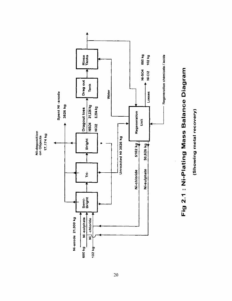
However, the entire dragout is not lost. First, they are recycled to bath; second, the unitmay resort to metal recovery. In case of unit F, where Ni recovery is practiced, thesefigures reduce to 600, 102 and 96 kg respectively as net loss through wastewater. Part ofBoric acid may be lost through evaporation, because the bath temperature is around 40° Cand bath is agitated by blown air. The mass balance diagram is shown in Fig. 2.1.
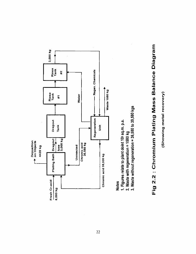
2.5.2 Chrome Plating
Here also, a calculation of Cr metal deposition is made first, using Faraday's law:Eei = 0.323y =-- 6.95i = 9.5 amp /dm 2
n = 15(%)t = 3 min ( Average for decorative chrome)F = 100 sq. m. = 10,000 dm'
G = 0.323 x 9.5 x 10,000 x 3 x 15
6,000 - 230 g i.e., 2.3 g per sq.m of CrOr correspondingly 2.30/0.52 = 4.42 g of anhydrous chromic acid per sq. m. of plated areaof decorative chrome
Using this figure in Unit H, plating area of 10 lakh sq. m. would need 4420 kg. Indecorative plating, only about 10% of the chromic acid added to the bath is deposited onobjects as plating. Unless recovered, the balance 90% would lead to losses. Also, there isdragout losses.
Estimate of dragout loss is calculated on the basis of Chrome bath constituentsChromic acid = 280 - 320 g/lSulphuric acid = 2.1 - 2.5 g/I
Total quantity lost in a year is calculated @ 1.0 litre of bath solution per 100 sq.m.
Chromic acid = 3000 kgSulphuric acid = 23 kg
However, the entire dragout is not lost. First, content of dragout tank is often recycled toplating bath; second, the unit may resort to Chromium recovery. Part of sulphuric acid
19
Ni-
deposit
ion
on
Ob
jects
17
,17
4 k
g
Sp
en
t N
i -a
no
de
3826 k
g
Ni-
anode 2
1,0
00 k
g
600 k
g
Ni -su
lph
ate
I S
em
i- I
Dragou
t lo
ss
Dra
g o
ut
Bri
gh
tT
ri-
Bri
ght
Ni
-chlo
ride
NIS
O4
31
,22
6 k
g
Tan
k1
02
kN
iCl2
5,20
4 kg
Rin
seT
an
ks
Wat
er
r') 0
Un
rea
cte
d N
i 3
82
6 k
g
Ni-
ch
lori
de
5f0
2 k
Regenera
tion
Un
itN
i-sulp
hate
30,6
26.k
gN
i-S
O4
60
0 k
g
Lo
sses
Ni-
C1
2 1
02
kg
Regenera
tion c
hem
icals
/"a
cid
s
Fig
2.1
: N
i-P
lati
ng
Mas
s B
ala
nce D
iag
ram
(Sh
ow
ing
meta
l re
co
very
)
may be lost through evaporation. The mass balance diagram for a plant doing decorativeCr-plating @10 lakh sq. m. is shown in Fig. 2.2.
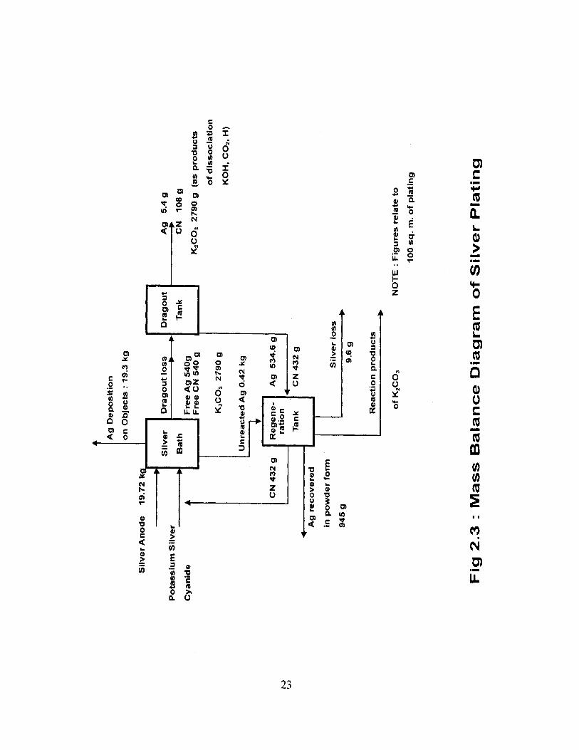
2.5.3 Silver Plating
First, a calculation of Ag metal deposition is made using Faraday's law:= 4.024
7 10.50i 0.4 amp /dm2
1 =99(%)t = 80 min ( range 75 to 90 min)F = 100 sq. m. = 10,000 dm 2
G=24.024x0.4x 10,000x80x99
6,000 - 19315.2 9 i.e., 0.193 kg per sq.m
For unit X, which carry out approximately 1800 sq. m.. of silver plating per year, theywould need 347.4 kg. In reality they spend 350 to 360 k g of Ag anode per year onaverage. So. actual conversion is 97.8%. The industry average is 99 to 99.5 %Therefore, 0.5 to 1% of Ag is lost/wasted.
Estimate of dragout loss is calculated on the basis of Potassium Silver Cyanidebath constituentsFree Silver = 30g/IFree Cyanide = 30g/lPotassium Carbonate == 150 to 160 g/I
Total quantity lost in a year is calculated 1.0 litre of bath solution per 100 sq.mFree Silver = 540 gFree Cyanide 540 gK2CO3 = 2790 g
However, the entire dragout is not lost. First, they are recycled to bath; second, the unitresorts to metal recovery. In case of unit X. where Ag recovery is practised, the total ofsilver cyanide and potassium cyanide is 3000 g . Since the individual quantities are notknown, the corresponding weight of K [Ag(CN) 2 is 996 g based on 80.5% silver contentn, 100% purity. If recovery is considered as 99 %, 5.4 g of Ag is net loss throughwastewater. The mass balance diagram is shown in Fig. 2.3.
2.5.4 Zinc Plating
In alkaline non-cyanide (cyanide free) process, a calculation of Zn metal deposition ismade using Faraday's Law:
= 1.219y =7.13
►pi
Dep
osi
tion
on
Ob
jects
44
20
kg
Fresh
Cr-a
cid
6,0
00 k
gP
lati
ng B
ath
Dragou
t
loss
3,0
00 k
g
Rin
seD
ragou
tT
an
k
Rin
seT
an
kT
an
k
#1
#2
3,0
00
kg
U n
reacte
dW
ate
rC
hrom
ic a
cid
36
,58
0 k
g
Reg
en
era
tio
n 4R
eg
en
.
Ch
em
icals
N
Un
it
IiC
hro
mic
acid
38
,00
0 k
g
Wa
ste 1
58
0 k
g
Note
s1.
Figu
res
rela
te to
pla
nt d
oint
105
sq.
m. p
.a.
2.W
aste
with
rege
nera
tion
=158
0 kg
3. W
aste
with
out r
egen
erat
ion
= 36
,580
to 3
9,58
0 kg
s
Fig
2.2
: C
hro
miu
m P
lati
ng
Mass B
ala
nce D
iag
ram
(Sh
ow
ing
meta
l re
co
very
)
Ag
Dep
osi
tio
n
on O
bje
cts
: 1
9.3
kg
Sil
ver
An
od
e 1
9.7
2
Po
tassiu
m S
ilver
Cyan
ide
Sil
ver
Dra
go
ut
loss
Bath
Fre
e A
g 5
40g
Fre
e C
N 5
40 g
K2C
O3 2
79
0 g
Un
reacte
d A
g 0
.42
kg
Dra
go
ut
Ag
5.4
g
Tank
CN
108 g
K2C
O3 2
79
0 g
(as p
rod
ucts
of
dis
so
cia
tio
n
KO
H, C
O2.
H)
N w
CN
432 g
Ag
recovere
d
in p
ow
der
form
94
5 g
Regene- A
g 5
34.6
gra
tio
n
Tank
CN
43
2g
Sil
ver
loss
9.6
g
Reacti
on
pro
du
cts
of
K2C
O3
NO
TE
: F
igu
res
rela
te t
o
100 s
q. m
. o
f p
lati
ng
Fig
2.3
: M
as
s B
ala
nce D
iag
ram
of
Silver
Pla
tin
g
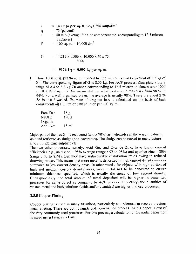
i = 14 amps per sq. ft. i.e., 1.506 amp/dm 2
T1 = 75 (percent)t = 40 min (average for auto component etc. corresponding to 12.5 micron
thickness)F — 100 sq. m. = 10,000 dm 2
G — 1.219 x 1.506 x 10,000 x 40 x 756000
= 9179.1 g = 0.092 kg per sq. m.
Now, 1000 sq.ft. (92.94 sq. m.) plated to 12.5 micron is mass eqivalent of 8.2 kg ofZn. The corresponding figure of G is 8.55 kg. For ACF process, Zinc platers use arange of 8.4 to 8.8 kg Zn anode corresponding to 12.5 micron thickness over 1000sq. ft. ( 92.9 sq. m.) This means that the actual conversion may vary from 98 % to94%. For a well-organised plater, the average is usually 98%. Therefore about 2 %Zn is lost / wasted. Estimate of drag-out loss is calculated on the basis of bathconstituents @ 1.0 litre of bath solution per 100 sq. m. :
FreeZn: 18gNaOH: 190 gOrganicAdditive: 15 ml.
Major part of the free Zn is recovered (about 90%) as hydroxides in the waste treatmentunit and retrieved as sludge (non-hazardous). The sludge can be reused to manufacturezinc chloride, zinc sulphate etc.The two other processes, namely, Acid Zinc and Cyanide Zinc, have higher currentefficiencies e.g., acid zinc — 95% average (range : 92 to 98%) and cyanide zinc — 80%(range : 60 to 85%). But they have unfavourable distribution ratios owing to reducedthrowing power. This means that more metal is deposited in high current density areas ascompared to low current density areas. In other words, for objects with high portion ofhigh and medium current density areas, more metal has to be deposited to ensureminimum thickness specified, which is usually the areas of low current density.Correspondingly, the total amount of metal deposited will be higher in these twoprocesses for same object as compared to ACF process. Obviously, the quantities ofwasted metal and bath solutions (acids and/or cyanides) are higher in those processes.
2.5.5 Copper Plating
Copper plating is used in many situations, particularly as undercoat to receive preciousmetal coating. There are both cyanide and non-cyanide process. Acid Copper is one ofthe very commonly used processes. For this process, a calculation of Cu metal depositionis made using Faraday's Law:
24
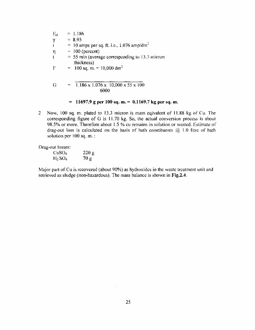
Eei = 1.186y =8.93i 10 amps per sq. ft. i.e., 1.076 amp/dm ,
tl - 100 (percent)t = 55 min (average corresponding to 13.3 micron
thickness)F = 100 sq. m. 10,000 dm`
G = 1.186x 1.076 x 10,000 x 55 x 1006000
= 11697.9 g per 100 sq. m. = 0.1169.7 kg per sq. m.
2 Now, 100 sq. m. plated to 13.3 micron is mass eqivalent of 11.88 kg of Cu. Thecorresponding figure of G is 1 1.70 kg. So, the actual conversion process is about98.5% or more. Therefore about 1.5 % cu remains in solution or wasted. Estimate ofdrag-out loss is calculated on the basis of bath constituents a 1.0 litre of bathsolution per 100 sq. m.
Drag-out losses:CuSO4 220 gH" SO4 70 g
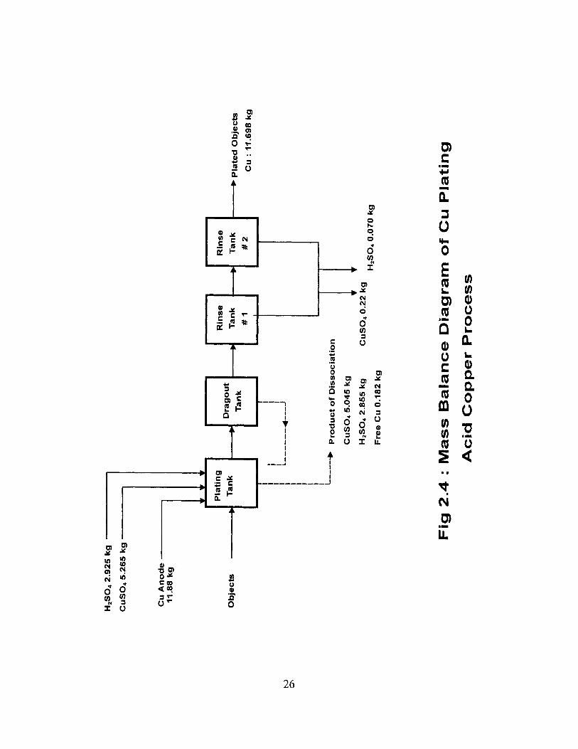
Major part of Cu is recovered (about 90%) as hydroxides in the waste treatment unit andretrieved as sludge (non-hazardous). The mass balance is shown in Fig.2.4.
25
H2504 2
.925
Cu
SO
4 5
.26:
Cu
An
od
e11.8
8 k
g
Ob
jects
Pla
ted
Ob
jects
Cu
: 1
1.6
98 k
g
H2S
O4 2
.855 k
g
Cu
SO
4 0
.22 k
g
Fre
e C
u 0
.182 k
g
H2S
O4 0
.070 k
g
Fig
2.4
: M
ass B
ala
nce D
iagram
of
Cu
Pla
tin
g
Acid
Cop
per P
rocess

Chapter 3
In-depth Studies in Electroplating Industry
3.1 General
In order to carry out an in-depth study of a variety of electroplating units, considerationswere given to various factors, such as - size of units (small, medium and large), locationof industry (i.e., across the country), type of platers (i.e., primary users, whomanufactures products in which electroplating is one of the manufacturing processes,such as bi -cycles, motorized two-wheelers, sanitary fixtures, etc and job work units, whorender plating services to components manufactured by others), plating materials (Zinc,Chromium-several varieties, Nickel, Copper, Brass, Precious materials ( Silver, Goldetc.) and technology used, as some of them practice improved methods.
3.2 Analysis of Results
The results of the in-depth study have been analysed with respect to the following• Type of units• Quality of Raw (Untreated) Wastewater• Quality of Treated wastewater• Water Use and Cost of Wastewater Treatment• Air Emission Status• Noise Emission Status
These are discussed in the subsequent paragraphs.
3.2.1 Type of Units
In the case of Electroplating, large units (with paid-up capital above Rs. 5 crore) arevirtually non-existent. There are 'primary users', who manufactures complete products,such as bicycles, motorised two-wheelers and automobiles (4-wheelers), in whichelectroplating is one of the manufacturing operations. These units can also be called' integrated units'. On the other hand, it is more convenient to classify these units on thebasis of turnovers. In such a case, classification can be easier, irrespective of the factwhether they are primary users, outsourced units of OE manufacturers or job-work units.Table 3.1 shows the distribution of units in the in-depth study.
Table 3.1: Distribution of Units in the Study
Gross Annual Turn-over Percent of Total Unit type> I crore 54 Large
Over 50 lakhs but under 1crore
14 Medium
Below 50 lakhs 32 Small
27

Consequently, all primary users and integrated units fall in the large category; these unitsgenerally tend to have mechanized and automatic handling and bath operation. They aremore likely to have fume collection system too or are in a position to do so.
3.2.2 Quality of Raw (Untreated) Wastewater
The characteristic quality of raw (untreated wastewater observed during in-depth study issummarised in Table 3.2 for various types of plating.. The following observations maybe noted:1. Ni- Cr plating:
In Ni-Cr plating wastewater, pH is usually acidic (mean pH being 2.9. TSS is not aconcern but TDS is high (mean at 2754 mg/I; In several units it was noticed thatalkaline rinse waste water are mixed with main wastewater from plating bath andrinsing tanks. In such cases, pH increases to near normal 7.41. This practiceunnecessarily requires more acid to be added to lower the pH to around 2.5 forreduction ofCr(Vl) to Cr(lII).
Both Cr(VI) and Cr (Total) are considerably high at 6.99 and 167.7 mg/L. Othermetals (Ni = 91.2 mg/I and Pb = 2.8) also require alkaline precipitation. Oil & Greaseand Total Residual Chlorine are not a matter of concern, because their values arewithin permissible limits of effluent for discharge.
2. Hard Chrome plating
Although there is no fundamental difference in plating with respect to Chromeplating, the wastewater indicated very high TDS and Cr concentrations; this is partlydue to the fact that rinse water volume is not as much as observed in decorativechrome plating and Ni-Cr plating. In other words, the wastewater is concentrated,having its own advantages and disadvantages. Removal of TDS is a seriousrequirement in final treatment of this kind of wastewater.
3. Blackening, Phosphating & Chromatting
The wastewater contains substantial concentration of Cr and Zn. pH is alkaline,because the sample was drawn from the neutralisation tank. Cyanide was rather low,because the effluent from cyanide oxidation is taken to neutralisation tank. Here too,TDS is high.
4. Zinc Plating
This is the most common plating activity throughout the country, almost equal to Ni-Cr plating. There are four processes which are in use.
In Alkaline Cyanide Free process, the wastewater has alkaline pH (mean 8.2).substantially high Zn (mean 26.4 mg/1), some copper (probably coming from copperundercoat); Oil & Grease is not a concern.
28

In Acid Cyanide process, Zn concentration is high; pH is normal, because wastewaterfrom Alkaline pre-cleaning is mixed with process bath and post-plating rinse water.The low cyanide concentration is inexplicable; perhaps large dilution water fromother operations are mixed with bath and rinse wastewater.
Wastewater from Alkaline Cyanide process has considerable concentration of Zn andcyanide, with high TDS. Other parameters are not of concern.
5. Acid Zinc (Cyanide Free)
This process is widely used in Madurai, Tamil Nadu, where in tiny and smallunits, there is no treatment given to the wastewater. Zinc concentration is highest(mean 1675 mg/I and the range is very wide) among all the process variants; infact it is incomparably high among others. Clearly, use of this requires immediateattention in regard to waste minimization as well as process modification.
3.2.3 Quali ty of Treated wastewater
Table 3.3 summarises the quality of treated wastewater from the plants studied. Thefollowing observations may be noted:
a) five units out of 21 units impart no treatment to wastewater; these are tiny/smallunits, pointing to a serious problem nationwide;
a) pH of treated wastewater is within desirable range.b) While the mean TSS is within acceptable limit, only in one unit, it is above limit.c) While there is no limit specified for TDS, in three units, it is above 2000 mg/I, a
point of concernd) Cr(VI) is generally within limit and does not cause any concerne) Cr(T) range is wide and high exceedence in limit is observed in three cases
indicating very clearly inadequate treatment.f) Ni-concentration meets standard in most cases;g) Zn concentration is within limit in most cases but exceeds in one,h) Cu conentration is within limiti) Oil & grease is not a matter of concern, generally within limitj) Cyanide is generally under limitk) Ammonia N is within limit; so is total residual Chlorine
In summary, the main concern is inadequate removal of Cr(T) and Zn, indicatinginadequate precipitation of metal sludge. Sludge handling and storage practices in manyunits are unsatisfactory, needs improvement. Conventional alkaline precipitationtreatment does not remove dissolved solids. It is very interesting to note that one CETP(run privately) provides quite satisfactory treatment, meeting all parameters and alsoremoving high TDS by reverse osmosis process.
29

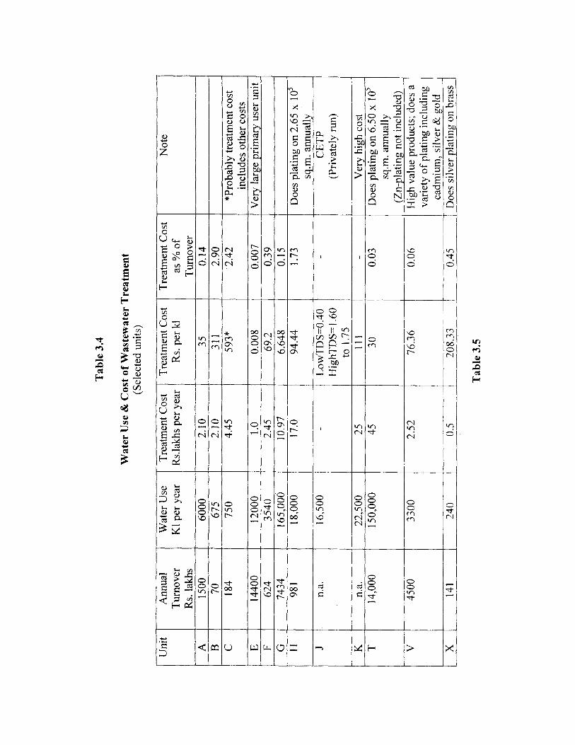
3.2.4 Water Use and Cost of Wastewater Treatment
The water use and cost of wastewater treatment are summarized in Table 3.4. It isobserved that water use varies widely among units owing to a large number of factors.Most units do not keep data on plating area due to the fact it is beyond industry practiceand that where they do job-work, pricing is done on weight basis. Surface measurement isseldom done. However, data from large integrated primary user units indicate that waterrequirement varies from 68 to 230 litres per sq.m. of plated surface area of Ni-Cr plating.In smaller unorganised units this would still be more. On comparison, World Bankrecommends a target of 1.3 litres per sq. m. of plated area for rack plating and 10 litresper sq. m of barrel plating where electroplating is routinely performed on objects withknown surface area. Clearly, water use in the industry in the country is far higher thansuch targets.
The of wastewater treatment varies rather widely. It is possible that accurate datamay not have been furnished by the industry; even ignoring extreme cases, the reportedrange is as wide as Rs. 30 to Rs. 311 per kl. In the privately run CETP, the charge leviedto customers vary from Rs. 0.50 to 1.25 for low TDS and Rs. 1.60 to 1.75 for high TDS .This makes sense that for medium, small and tiny units it would be genuinely economicalto treat wastewater in a CETP, even by tankering. However, where the units treat theirown wastewater, the cost of treatment is always below the generally accepted upper limitof 3% of total cost of production.
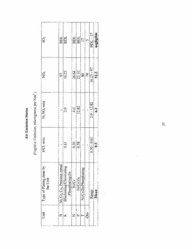
3.2.5 Air Emission Status
Electroplating give rise to fugitive emission from baths and pre-treatment tanks ofelevated temperature. Vapours also emanate from baths at ambient temperature. Principalconstituents of concern are acid fumes, gaseous pollutants and VOCs. Table 3.5 showsambient air pollutants. It is observed that the fugitive emission levels are not high butacid fume levels can be reduced substantially by fume collection and scrubbing withwater- rather simple techniques.
3.2.6 Noise Emission Status
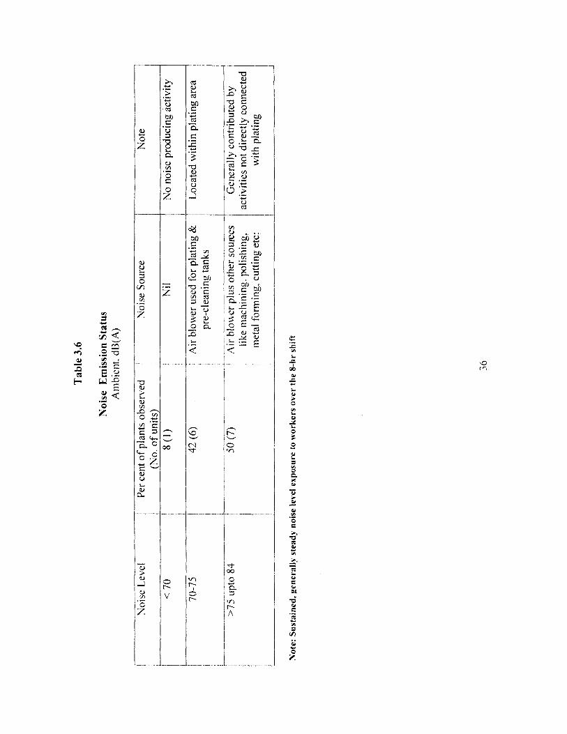
Electroplating in itself does not involve any noise producing activity. The main cause isair blowers, used to supply air to tank agitation for pre-cleaning and some baths (e.g.Watts Nickel bath). In most cases, these are located close to plating tanks working areaand workers are subjected to a sustained high noise level; predominant cause of highernoise level [higher than 75 and upto 84 dB(A)] is other industrial activity under sameshed like machining, metal forming, stamping, forging etc. Table 3.6 summarizes thedata.
30

Tab
le 3
.2
Su
mm
ary
of
Ra
w W
ast
ewa
ter
Qu
ali
ty(m
g/1,
exc
ept p
H)
Act
ivity
Par
amet
ers
(Ran
ge &
Mea
n)
HTS
ST
DS
Cr(
VI)
Cr
(T)
Ni
Zn
Pb
Cd
Cu
0+
GC
N3
Ni-
Cr
2.2
-3.5
8-6
10
1358
-0.
01-
2.0-
2.85
--
2.8
2-14
.6-
Pla
tin
g(2
.9)
(12.
3.7)
4582
5389
638
7.5
376.
5se
e N
ote
1(2
754)
see
No
te 3
(167
.7)
(91.
2)(8
.3)
(6.9
9)H
ard
Ch
rom
e2.2
-4.3
388
1454
71.
01-1
4.0
2.03
--
--
7.8
(3.1
)se
e N
ote
2(7
.5)
1592
(452
)se
e N
ote
2
Bla
cken
ing
,9.
712
139
44B
DL
21.5
-21
-7.
80.
05P
hosp
hati
ng
Ch
rom
att
ing
Cd p
lati
ng
10.1
710
.058
30-
-10
.69
36.2
80.
043
35.4
3N
. D.
0.10
9A
gp
lati
ng
8.5
174
1469
--
-3.
341.
23-
22.1
9N
.D.
0.06
_P1!
!!!A
u
!L7.
2-9.
211
529
40-
--
10.2
-C
u-
Cy
an
ide
Fre
e(8
.2)
42:6
=9.7
6Z
n(2
6.4)
Aci
d C
yan
ide
7.3-
7.62
134
3036
--
-34
.6-
0.01
4Z
n
31

Alk
alin
e'7
.62-9
.7
I 7.
62-9
.7
135
-121
i39
44-
-I 5
.6—
(0.
01-
!0.
01-
Cya
nid
e Z
n(7
8)
5178
2122
.64
'22
.64
(456
1)i
(13.
3)(7
.57)
i X7.
57)
Aci
d Z
inc
3.5
34-1
00 1
914-
1-
-25
--
!-
(Cya
nid
e F
ree)
!(6
7)60
0833
25(3
961)
(167
5)
J
Note
s1.
Whe
re a
lkal
ine
soak
rin
se w
aste
wat
er i
s m
ixed
wit
h pl
atin
g ta
nk a
nd r
inse
wat
er, p
H i
ncre
ases
to
a ra
nge
of 6
.58
— 7
.90,
wit
hm
ean
valu
e at
7.4
1. O
bvio
usly
suc
h w
aste
wat
er w
ill r
equi
re a
cid
addi
tion
to
low
er p
H f
or C
hrom
ium
red
ucti
on2.
In o
ne t
iny
hard
chr
ome
unit
, the
re i
s no
tre
atm
ent
give
n be
caus
e of
ver
y sm
all
volu
me,
inc
reas
ing
the
conc
entr
atio
n of
pol
luta
nts
to h
igh
leve
l, sh
own
here
.3.
In o
ne p
lati
ng u
nit
doin
g du
ll &
bri
ght
Nic
kel
on C
hrom
e, w
aste
wat
er i
s hi
ghly
con
cent
rate
d, s
how
ing
Cr(
VI)
con
cent
rati
on a
t53
896
m4g
/I4.
The
larg
e va
riat
ion
in c
once
ntra
tion
of
Cr,
Ni w
aste
wat
er is
mai
nly
due
to w
ide
vari
atio
n in
qua
ntum
of
wat
er u
sed
for
rins
ing

Tab
le 3
.3
Sum
mar
y of
Tre
ated
Was
te w
ater
Qua
lity
(mg/
l. ex
cept
pH
)
Plan
t Act
ivity
Para
met
ers _
____
_pH
jT
SS
TD
SI
Cr
(VI)
Cr(
T)
Ni
Cu
Zn
ICd
Ag
0 &
iC
NN
H3
TR
CG
1-N
Cr,
Ni-
Cr
&6.
85-
26.4
-11
00-
1B
DL-
0.1-
40
10.
11-
1.76
0.19
-4.
0-1
0.02
-3.
80<0
.01
Zn
plat
ing
7.8
5474
210.
06(0
.484
)2.
503.
87
i5.
8i
0.21
(7.4
1)(4
0.1)
(342
2)(0
.024
)1
(1.3
3)
((1
.24) t
(4.9
)(0
.11
L_____________
5)
Bra
ss, C
r, N
i,______
9.24
_____
I 9.0
j31
50____
10
.04
BD
L
1.7
6.
3.87
_______
;4.
0B
DL
BD
L<
0.05
Cu
plat
ing.
iC
d P
lati
ngI
7.38
12.0
1340
4.0
BD
L
Í-
0.9
3;
-j
1.72
37.
93B
DL
0.10
1B
DL
<0.
05A
g P
lati
ng(
7.25
10.4
T14
38-
--
0.20
0.17
3-^
xxB
DL
' BD
LB
DL
<0.
05P
hosp
hati
ng.
8.2-
8.5
1.8-
1026
-i;
BD
L
BD
L-
--
2-21
-0.
03-
Chr
omat
ting
&
148
1637
2.2
Bla
cken
ing
'
^0.
09
CE
TP
- l
ow
8.5
15
55
BD
L
BD
L
j1.
75
BD
L !
0.1
3 i4 0.03
-<
0.5
TD
S stream
a
Tab
le 3
.4
Wat
er U
se &
Cos
t of
Was
tew
ater
Tre
atm
ent
(Sel
ecte
d un
its)
Uni
tA
nnua
lW
ater
Use
Tre
atm
ent
Cos
tT
reat
men
t C
ost
Tre
atm
ent
Cos
tN
ote
Tur
nove
rK
1 pe
r ye
arR
s.la
khs
per
year
Rs.
per
ki
as %
of
Rs.
lakh
sT
urno
ver
A15
0060
002.
1035
0.14
B70
675
2.10
311
2.90
C18
475
04.
4559
3*•2
.42
*Pro
babl
y tr
eatm
ent
cost
incl
udes
oth
er c
osts
E14
400
1200
01.
00.
008
0.00
7V
ery
larg
e pr
imar
y us
er u
nit
F62
435
402.
4569
.20.
39G
7434
165,
006
10.9
76.
648
0.15
H98
118
,000
17.0
94.4
41.
73D
oes
plat
ing
on 2
.65
x 10
'sq
.m. a
nnua
lly
Jn.
a.16
,500
i-
Low
TD
S=
0.40
-C
ET
PH
ighT
DS=
] .6
0(P
riva
tely
run
)to
1.7
5K
n.a.
22,5
0025
111
-V
ery
high
cos
tT
14,0
0015
0,00
045
300.
03D
oes
plat
ing
on 6
.50
x 10
'sq
.m. a
nnua
lly
(Zn-
plat
ing
not
incl
uded
)V
4500
3300
2.52
76.3
60.
06H
igh
valu
e pr
oduc
ts;
does
ava
riet
y of
pla
ting
incl
udin
gca
dmiu
m, s
ilve
r &
gol
dX
141
240
0.5
208.
330.
45D
oes
silv
er p
lati
ng o
n br
ass
Tab
le 3
.5
Air
Em
issi
on S
tatu
s
(Fug
itiv
e E
mis
sion
, mic
rogr
ams
per
Nm
3 )
Uni
tT
ype
of P
lati
ng d
one
byth
e U
nit
HC
L m
ist
H2
SO4
mis
tN
O,
SO2
BN
i, C
r, C
u, P
reci
ous
met
al-
-97
BD
LK
Bla
cken
ing/
Chr
omat
ing
/Pho
spha
ting
/Zn
0.61
2.0
16.2
3B
DL
NN
i/C
r0.
304.
026
.64
BD
LP
Ni/
Cr/
Zn
0.58
12.8
222
.10
BD
LT
Ni/
Cr/
Zn/
Pho
spha
ting
--
8017
-Do-
--
745
r—R
ange
0.30
- 0.
612.
0 - 12
.82
16.2
3 - 97
BD
L —
17
Mea
n0.
56.
352
.3_
_ne
glig
ible
35
Tab
le 3
.6
Nois
e E
mis
sion S
tatu
sA
mbie
nt. d
B(A
)
Noi
se L
evel
Per
cen
t of
pla
nts
obse
rved
(No.
of
unit
s)N
oise
Sou
rce
,N
ote
< 7
0!
8(1
)N
ilN
o n
ois
e pro
duci
ng a
ctiv
ity
70-7
542
(6)
Air
blo
wer
use
d fo
r pl
atin
g &
Loc
ated
wit
hin
plat
ing
area
pre-
clea
ning
tank
s
>7^
upt
o 84
50 (
7)rt
Air
blo
er p
lus
othe
r so
urce
sG
ener
ally
con
trib
uted
by
like
mac
hini
ng, p
olis
hing
,ac
tivi
ties
not
dir
ectl
y co
nnec
ted
met
al f
orm
ing,
cut
ting
etc
: w
ith p
lati
ng
Note
: S
ust
ain
ed,
gen
eral
ly s
tead
y n
ois
e le
vel
ex
po
sure
to
wo
rker
s o
ver
th
e 8
-hr
shif
t
36
3.3 Summary of Findings
The findings of in-depth study is summarized as :• Electroplating by itself may not constitute to he a large industry by conventional
definition of paid-up capital. Big electroplating units are always a part of integratedindustrial production (automobiles, cycles etc.), referred to in this study as primaryusers' These units arc usually mechanized, operated with semi-automated processcontrol and better in pollution control, often employing metal recovery, rinse waterrecirculation and fume collection system.
2. Vast majority of units are small — proprietary, partnership or private limited entities(turnover ranging from as low as 10 lakfis to 5 crores), these units vary widely in set-up, plating process control, degree of mechanization, pollution control techniques andability to modernize due to several reasons. These units with almost total manualoperation and with little technical supervision need to be upgraded with various levelsof BAT, as identified in Chapter 5.
3. Largest number of units are engaged in Ni -Cr and 7.n plating; wastewatercharacteristics vary widely mainly due to unorganized handling, wasteful rinsing, lackof process control. Large number of such units do not have any wastewater treatmentt^icility, discharging their untreated wastewater into municipal drains
Where treatment is dine, reduction of'Cr (VI) to Cr (I11) is generally satislactor\but wastewater often contains high levels of Cr('l') and %n, indicating inadequateprecipitation of metal sludge. This holds good for Cadmium and other plating too.No problem is found with respect to other pollutants. .!t is very interesting to notethat one CETP (run privately) provides quite satisfactory treatment, meeting allparameters and also removing high TDS by reverse osmosis process
4. Sludge handling and storage practices in many units are unsatisfactory, needsimprovement, particularly it contains hazardous materials.
5. Conventional alkaline precipitation treatment does not remove dissolved solids. Mosteffluents contain higher than 1800 mg/I, a figure often used as limit in other industrialwastewater. Even with sand filtration followed by activated carbon filtration. TDS ashigh as 3404 mg/I is noted.
6. Data from large integrated primary user units indicate that water requirement variesfrom 68 to 230 litres per sq.m. of plated surface area of Ni -Cr plating. In smallerunorganised units this would still be more. As comparison, World Bank recommendsa target of' 1.3 litres per sq. m. of plated area for rack plating and 10 litres per sq. mof' barrel plating where electroplating is routinely performed on objects with knownsurface area. Clearly, water use in the industry in the country is far higher than suchtargets.
7. Cost of' wastewater treatment varies widely range being Rs. 30 to Rs. 311 per kl.Scale of operation is one of the main reasons - larger the plant, lesser is the cost perkl. In the privately run CETP, the charge levied to customers vary from Rs. 0.50 to1.25 for low TDS and Rs.1.60 to 1.75 for high i'DS . This makes sense that formedium, small and tiny units it would be genuinely economical to treat wastewater ina CETP, even by tankering their wastewater.
8. Where the units treat their own wastewater, the cost of treatment is always below thegenerally accepted upper limit of 3% of total cost of production.
37

9. As far as air pollutant emission is concerned, the fugitive emission levels are not highbut acid fume levels can be reduced substantially by fume collection and scrubbingwith water- rather simple techniques.
10. In most cases, worker exposure to average noise level is upto 75 dB(A). Whereworkers are subjected to a sustained high noise level; predominant cause of highernoise level [higher than 75 and upto 84 dB(A)] is found to be other industrial activityclose by and under same shed such as machining, metal forming, stamping, forgingetc
Ambient air quality due to fugitive emission of filmes and vapours were studied. It wasfound that the oxides of Sulphur and Nitrogen are quite within the limits of concentrationof ambient air. As far as acid mist concentrations are concerned, the averageconcentration of H2 SO4 is 6.0 mg/ Nm 3 . The 1-ICI mist concentrations are negligible.However, this is to be viewed with respect to international standard because there is nostandard for this parameter in India.
Chapter 4
Recovery of Metals
4.1 General.
During electroplating operations, metal salts are used partly by electro-deposition ofmetals and partly by rinsing and washing. While the first part goes into plating, thesecond part is lost and actually poses a problem in wastewater treatment. Even in platingbaths, solutions often needs to be discarded because of presence and build-up ofimpurities that either hinder the efficiency of plating process or cause deterioration inquality of plating. Either way, the baths are to be discarded before fresh bath is made.This is indeed a waste both in monetary terms and environmental considerations. Bathregeneration is therefore done to counter discarding it entirely.
Various methods are used for regeneration of baths and contents of pre-treatment, rinseand wash tanks. These methods are briefly described below with their specific advantagesand constraints of use. Of these methods, metal recovery through ion-exchange presentshighest potential and serves the dual purpose of resource (metal) recovery and wasteminimisation (by re-use of water of regenerated bath solutions). Hence this processwould be discussed in more detail.
4.2 Filtration & Centrifugation
Filtration with or without centrifugation is one of the widely used and effective methodsfor prolonging and improving the life of bath. Although it does not directly recovermetals, it enhances the use of metal salts thus controlling and reducing the wastage ofmetal salts.
Activated carbon filter is widely used to remove dissolved organic impurities (example:Nickel Baths) in addition to its action in removing solids. Such filters are usedcontinuously or intermittently during plating.
The removal of oils from alkaline cleaners by ultrafiltration considerably prolongs the lifeof treatment baths and reduces interference by oils with flocculation and settling stepsduring clarification. Separation of the grease film from degreasing baths is anotherexample of the use of centrifugation or filtration. However, these are not generally usedin small-scale operations. The advantages of these techniques are:
• Fast regeneration of treatment baths with high efficiency;• Production work does not have to be interrupted;• Wastes resulting from these are highly concentrated and thus could be
recovered;• Disposal of residues is easier due to low volumes and more convenient with
sludge disposal operations of the ETPNewer methods and technologies have come up such as hydro-cyclones, packed-mediafilters and electrolytically enhanced cross-flow membrane etc.
39
4.3 Evaporation4.3.1 General
Evaporation losses are considerable in hot baths, such water losses can be compensatedby recycling cascade rinsing (last tank of cascade). In theory, if the if the effluent rateequals the evaporation rate, a complete recovery of bath chemicals can he achieved. Evenif complete recovery is not achieved, substantial recovery can easily be obtained.
4.3.2 Simple Measures
As the simplest example, the direct recovery of plating baths is realised with a staticdragout tank. Rinse water from this tank is used for the replenishment of volume losses ofthe process bath due to the evaporation. Periodic water transfer from dragout into theprocess tank is made manually or better by a small pump. Practical recovery ratio realisedby this method is not usually higher than 50 -- 60 %. Many platers in the small scalesector in India employs this technique.
As an improvement to above, in case of cold bath, the dragouts and contents of first staticrinse tanks can be concentrated by forced evaporation. However, application will dependon the trade-off between energy and operating cost versus cost of recovered chemicals(such as metal salts). Clearly, this technique is used in case of expensive chemicals. Amore desirable method would be to use condenser, which would enable to recirculate thecondensate (water) to rinse tanks and chemicals to bath.
4.3.3 Advanced Techniques — Tin, Copper, Zinc etc.
Efficiency of direct recovery can be significantly improved by the introduction of severaldrag-out/rinse tanks arranged in series. Such a technique has been developed in Polandand applied in Poland and several countries with encouraging results. Air lift pumps(made of PVC) are used for rinse water transfer from tank to tank and from the first rinsetank to the plating tank.(Fig 4.1.). The return rates and opening and closing of valves areautomated (controlled by electronic level controller and conductometric probes).Depending upon the plating line output, the evaporation losses of the bath and the spaceavailable in the shop, 4 dragout tanks in a series can be introduced. The tanks can work inclosed loop system with zero discharge. This technique has been successfully used forNickel, Tin and Copper plating baths and other hot baths recovery with an efficiency of85 -- 95%. It has also been used for recovery of cold baths such as Zinc, wherein a smallevaporator is used. Such a system for Zinc barrel plating line has been quite successful.Recovery ratio of Zn plating bath was 98% (about 300kg Zn per year). Average waterconsumption for rinsing was reduced from 200 1/ sq.m. to 18 I/sq.m., i.e., achieving arinse-water reduction of 91%. Other savings included:
1. Reduction of Energy cost in plating shop2. Reduction of consumption of anode and plating salts3. Reduction in cost of waste water treatment4. Reduction of sludge volume
40
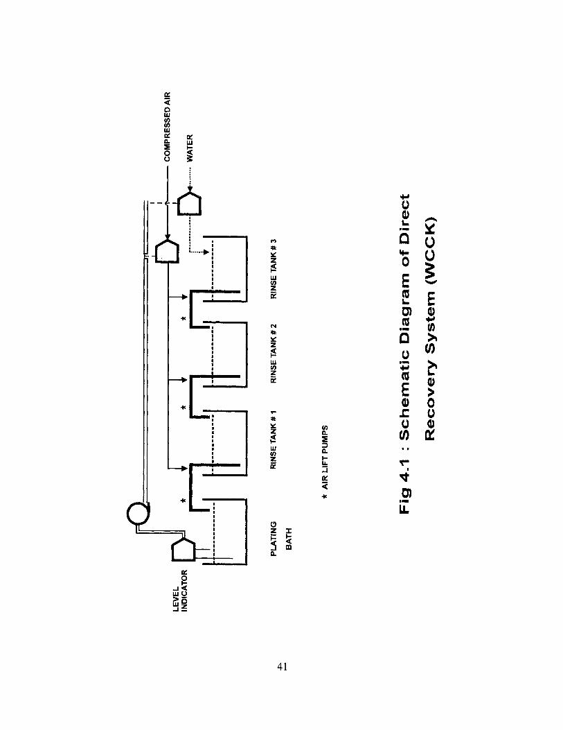
LE
VE
L
IIi
CO
MP
RE
SS
ED
AIR
IND
ICA
TO
R Ç
'TÏI9
_flF
1E'1
t-----------.
........ W
AT
ER
PL
AT
ING
RIN
SE
TA
NK
# I
RIN
SE
TA
NK
#2
RIN
SE
TA
NK
# 3
BA
TH
* A
IR L
IFT
PU
MP
S
Fig
4.1
: S
chem
ati
c D
iagram
of D
irect
Recovery
Syste
m (
WC
CK
)
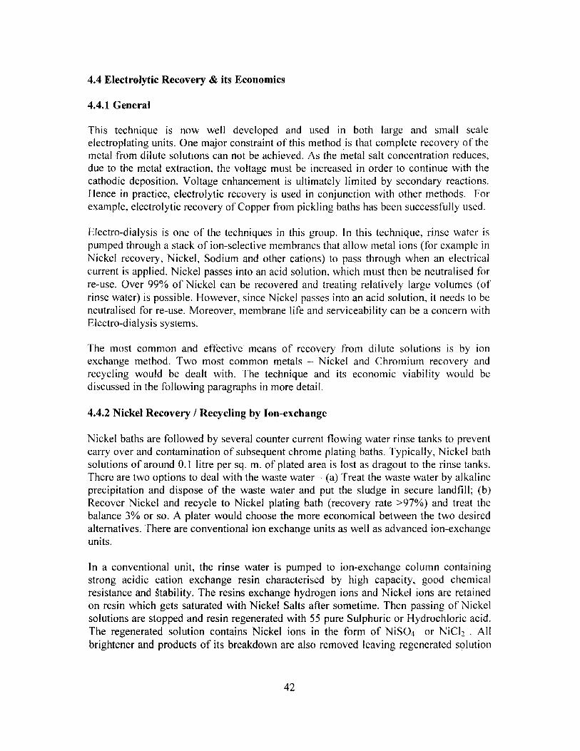
4.4 Electrolytic Recovery & its Economics
4.4.1 General
This technique is now well developed and used in both large and small scaleelectroplating units. One major constraint of this method is that complete recovery of themetal from dilute solutions can not be achieved. As the metal salt concentration reduces,due to the metal extraction, the voltage must be increased in order to continue with thecathodic deposition. Voltage enhancement is ultimately limited by secondary reactions.Hence in practice, electrolytic recovery is used in conjunction with other methods. Forexample, electrolytic recovery of Copper from pickling baths has been successfully used.
Electro-dialysis is one of the techniques in this group. In this technique, rinse water ispumped through a stack of ion-selective membranes that allow metal ions (for example inNickel recovery, Nickel, Sodium and other cations) to pass through when an electricalcurrent is applied. Nickel passes into an acid solution, which must then be neutralised forre-use. Over 99%,ó of Nickel can be recovered and treating relatively large volumes (ofrinse water) is possible. However, since Nickel passes into an acid solution, it needs to beneutralised for re-use. Moreover, membrane life and serviceability can be a concern withElectro-dialysis systems.
The most common and effective means of recovery from dilute solutions is by ionexchange method. Two most common metals — Nickel and Chromium recovery andrecycling would be dealt with. The technique and its economic viability would bediscussed in the following paragraphs in more detail.
4.4.2 Nickel Recovery / Recycling by Ion -exchange
Nickel baths are followed by several counter current flowing water rinse tanks to preventcarry over and contamination of subsequent chrome plating baths. Typically, Nickel bathsolutions of around 0.1 litre per sq. m. of plated area is lost as dragout to the rinse tanks.There are two options to deal with the waste water — (a) Treat the waste water by alkalineprecipitation and dispose of the waste water and put the sludge in secure landfill; (b)Recover Nickel and recycle to Nickel plating bath (recovery rate >97%) and treat thebalance 3% or so. A plater would choose the more economical between the two desiredalternatives. There are conventional ion exchange units as well as advanced ion-exchangeunits.
In a conventional unit, the rinse water is pumped to ion-exchange column containingstrong acidic cation exchange resin characterised by high capacity, good chemicalresistance and'stability. The resins exchange hydrogen ions and Nickel ions are retainedon resin which gets saturated with Nickel Salts after sometime. Then passing of Nickelsolutions are stopped and resin regenerated with 55 pure Sulphuric or Hydrochloric acid.The regenerated solution contains Nickel ions in the form of NiSO.z or NiCl2 . Allbrightener and products of its breakdown are also removed leaving regenerated solution
42
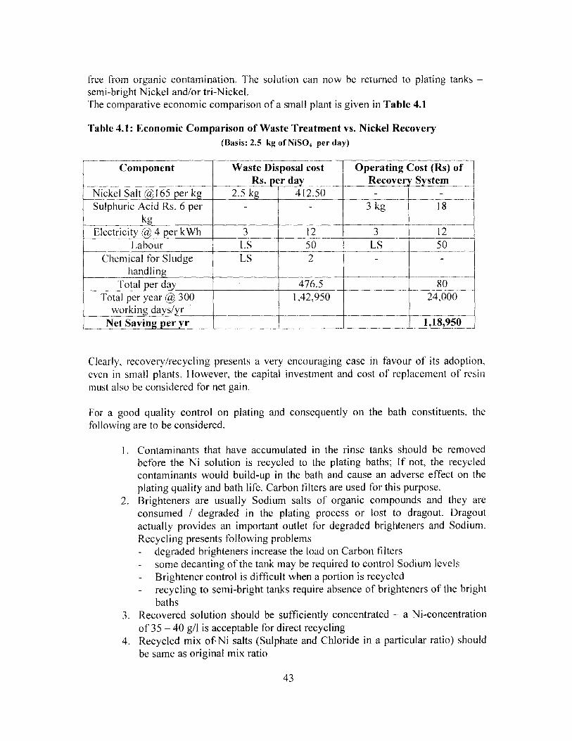
free from organic contamination. The solution can now be returned to plating tanks —semi-bright Nickel and/or tri -Nickel.The comparative economic comparison of a small plant is given in Table 4.1
Table 4.1: Economic Comparison of Waste Treatment vs. Nickel Recovery
(Basis: 2.5 kg of NiSO4 per day)
Component Waste Disposal cost_ pey
Operating Cost (Rs) ofRecover System _
Nickel Salta 165 per kg 2.5 kg 412.50 - -_Sulphuric Acid Rs. 6 per
kg- - 3 kg 18
Electricity 4 per kWh 3 12 __ 12^__Labour LS 50 LS 50
Chemical for Sludgehandling
LS 2 - -
Total per day 476.5 80Total per year @ 300
working days/yr1,42,950 24,000
Net Saving_per r 1,18,950
Clearly, recovery/recycling presents a very encouraging case in favour of its adoption,even in small plants. However, the capital investment and cost of replacement of resinmust also he considered for net gain.
For a good quality control on plating and consequently on the bath constituents, thefollowing are to be considered.
I. Contaminants that have accumulated in the rinse tanks should be removedbefore the Ni solution is recycled to the plating baths; If not, the recycledcontaminants would build-up in the bath and cause an adverse effect on theplating quality and bath life. Carbon filters are used for this purpose.
2. Brighteners are usually Sodium salts of organic compounds and they areconsumed / degraded in the plating process or lost to dragout. Dragoutactually provides an important outlet for degraded brighteners and Sodium.Recycling presents following problems- degraded brighteners increase the load on Carbon filters- some decanting of the tank may be required to control Sodium levels- Brightener control is difficult when a portion is recycled- recycling to semi-bright tanks require absence of brighteners of the bright
baths3. Recovered solution should be sufficiently concentrated — a Ni-concentration
of 35-40 g/1 is acceptable for direct recycling4. Recycled mix of Ni salts (Sulphate and Chloride in a particular ratio) should
be same as original mix ratio
43
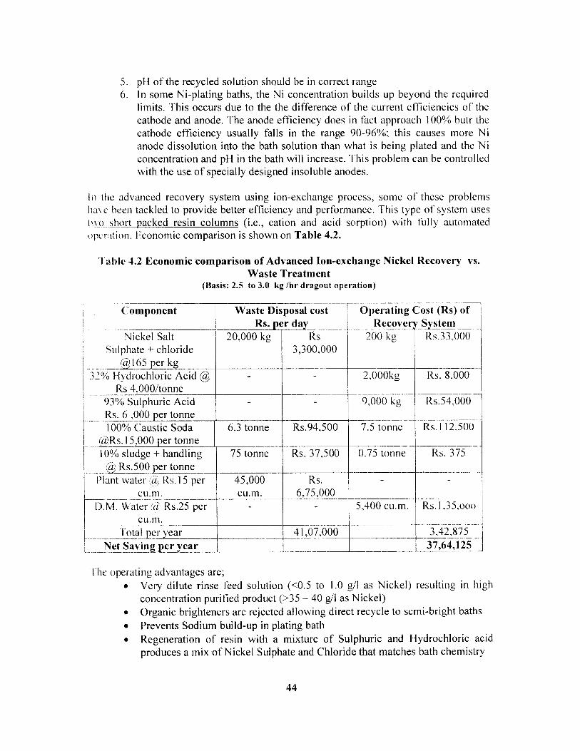
5. pH of the recycled solution should be in correct range6. In some Ni-plating baths, the Ni concentration builds up beyond the required
limits. This occurs due to the the difference of the current efficiencies of thecathode and anode. The anode efficiency does in fact approach 100% butr thecathode efficiency usually falls in the range 90-96%; this causes more Nianode dissolution into the bath solution than what is being plated and the Niconcentration and pH in the bath will increase. This problem can be controlledwith the use of specially designed insoluble anodes.
In the advanced recovery system using ion-exchange process, some of these problemshave been tackled to provide better efficiency and performance. This type of system usesto short packed resin columns (i.e., cation and acid sorption) with fully automatedoperation. l;conomic comparison is shown on Table 4.2.
Table 4.2 Economic comparison of Advanced Ion-exchange Nickel Recovery vs.Waste Treatment
(Basis: 2.5 to 3.0 kg /hr dragout operation)
- ------- - -- ---- ----Component Waste Disposal cost Operating Cost (Rs) of
Rs. per d --- Recove SystemNickel Salt 20,000 kg Rs 200 kg Rs.33,000
Sulphate + chloride 3,300,0001 65 perkT — _
32% Hydrochloric Acid @ - 2,000kg Rs. 8,000Rs 4,000/tonne
93% Sulphuric Acid - - 9,000 kg Rs.54,000Rs. 6 , 000 per tonne100% Caustic Soda 6.3 tonne Rs.94,500 7.5 tonne Rs.1 12,500
Rs. l 5 ,000 per tonne10% sludge + handling 75 tonne Rs. 37,500 0.75 tonne Rs. 375
à, Rs.500 per tonnePlant water (à; Rs. 15 per 45,000 Rs. - -
cu.m. cu. m. 6,75,000D.M. Water (1 Rs.25 per - - 5,400 cu.m. Rs.l 35,000
cu. m .3,42,875
--- — ------ Total per year--- ------
41,07 ,000-------
j Net Saving per year 37,64,125
i he operating advantages are;• Very dilute rinse feed solution (<0.5 to 1.0 g/1 as Nickel) resulting in high
concentration purified product (>35 — 40 g/l as Nickel)• Organic brighteners are rejected allowing direct recycle to semi-bright baths
• Prevents Sodium build-up in plating bath• Regeneration of resin with a mixture of Sulphuric and Hydrochloric acid
produces a mix of Nickel Sulphate and Chloride that matches bath chemistry
44

• Excess regenerant acids from the initial product of the first resin bed aresorbed out in the second resin bed resulting in the final Nickel productshaving a pH suitable for direct recycle.
4.4.3 Chrome Recovery / Recycling by Ion-exchange
In decorative plating, only about 15% of Chromic Acid added to the bath actually getsplated on the objects. The balance is lost as dragout to rinses and fume scrubbers. Clearlythis indicates a huge waste of metal, which is also very hazardous. Moreover, decorativeas well as hard chrome plating baths become contaminated over a period of time due todissolution of metals from the plated components and other operational factors. Thesedissolved cationic contaminants (trivalent Cr, Fe, Ni, Cu, Zn etc.) lower the throwingpower of the bath and lower current densities. This results in slower plating operation,consuming more energy, Plating quality is also adversely affected. All these factorstogether (i.e., defects in surface coating, material loss and costs of treatment and disposalto comply with pollution control regulations) lead to purification and recycling ofChromic Acid.
Conventional ion-exchange based recovery system comprises cation and anion exchangecolumns. The first column, containing cation exchange resin, removes trivalent Cr, Ni,Fe, Cu etc. The effluent, then containing only hexavalent Cr is passed through anionexchange resin. This removes hexavalent Cr, leaving the effluent free from all metal ions.When the resins get saturated, they are regenerated and recovered Chromic Acid isrecycled to baths. The economic comparison is shown in Table 4.3
The cost of a typical locally manufactured plant (of 2.5 kg Chromic Acid recovery costsabout Rs. 1,00,000 with a resin volume of 50 litres. The cost of resin is Rs. 600 per litrewith minimum life of 1 year (average life is between 2 to 3 years). The depreciationavailable on the investment is 100 %. Therefore pay back period is about a year.
Table 4.3: Economic Comparison of Waste Treatment vs. Chrome Recovery(Basis: 2.5 kg of Chromic Acid from static Rinse Water per day)
Component Waste Disposal cost Operating Cost (Rs) ofRs. er da _ Recovery System
Chromic Acid @110 per 2.5 kg 275 - -k
Sodium Metabisulphite @ 7.5 kg 90 - -Rs. 12 per kg
Caustic Soda @ Rs. 14 per 4 kg 56 4 kg 56
k gSaving on Sulphuric Acid 2 kg 6 3 kg 12
Rs. 3 per kg3 12Electricit a, 4 er kWh 10 40
50Labour LS 50 LS
45
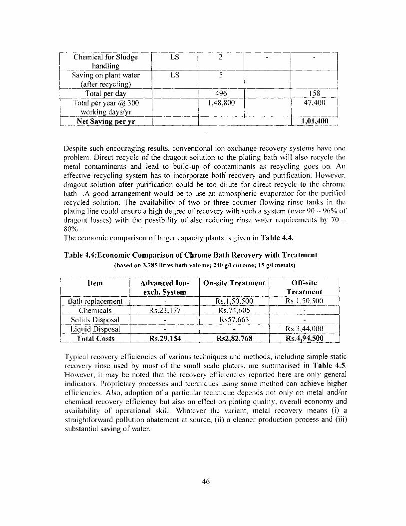
Chemical for SludgeL handlingLS 2 -
_-
Saving on plant water(after recycling)
LS 5_ _
Total per day 496 158Total per year @ 300
working days/yr1,48,800
- --- -- -- ---
47,400
---------1,01,400Net Saving per yr
Despite such encouraging results, conventional ion exchange recovery systems have oneproblem. Direct recycle of the dragout solution to the plating bath will also recycle themetal contaminants and lead to build-up of contaminants as recycling goes on. Aneffective recycling system has to incorporate both recovery and purification. However,dragout solution after purification could be too dilute for direct recycle to the chromebath .A good arrangement would be to use an atmospheric evaporator for the purifiedrecycled solution. The availability of two or three counter flowing rinse tanks in theplating line could ensure a high degree of recovery with such a system (over 90 - 96% ofdragout losses) with the possibility of also reducing rinse water requirements by 70 -80% .The economic comparison of larger capacity plants is given in Table 4.4.
Table 4.4:Economic Comparison of Chrome Bath Recovery with Treatment(based on 3,785 litres bath volume; 240 g/l chrome; 15 g/l metals)
Itemn Advanced Ion-exch. System
On-site Treatment Off-siteTreatment
Bath replacement - Rs. 1,50,500 Rs. 1,50,500Chemicals Rs.23,177 Rs.74,605 -_
Solids Disposal - Rs57,663Liquid Disposal - - Rs.3,44,000
Total Costs Rs.29,154 Rs2,82.768 Rs.4,94,500
Typical recovery efficiencies of various techniques and methods, including simple staticrecovery rinse used by most of the small scale platers, are summarised in Table 4.5.However, it may be noted that the recovery efficiencies reported here are only generalindicators. Proprietary processes and techniques using same method can achieve higherefficiencies. Also, adoption of a particular technique depends not only on metal and/orchemical recovery efficiency but also on effect on plating quality, overall economy andavailability of operational skill. Whatever the variant, metal recovery means (i) astraightforward pollution abatement at source, (ii) a cleaner production process and (iii)substantial saving of water.
46

4.5 Reverse Osmosis
Reverse Osmosis is one of the membrane filtration techniques, in which the pore size ofthe membrane varies from I to 15 Angstrom and the liquid is filtered through a semi-permeable membrane, which allows only water molecules since the pressure is more thanthe osmotic pressure. Application of this process is based on the fact that since the ROmembrane normally rejects compounds and ions above a molecular weight of 150. mostof the ions will be rejected. When rinse water is subjected to RO, water (with somecompounds) will conic out as permeate and the rest of the chemicals will remain in theconcentrate or rejects. The concentrate can be recycled to bath. This is possible whenrinses from various processes are segregated. ff they are mixed, the concentrate willcontain a variety of chemicals and obviously, it will need to be evaporated (with solarenergy) and sludge disposed as hazardous sludge. The major limiting factor for use of ROsystem is the presence of Iron and free chlorine, which the membranes are not ai -HIe towithstand, causing fouling of membrane. If sufficient pre-treatment precedes R(?. t henn itis a viable alternative to conventional system.
The process has been in use in BIEL, Trichy since the last four years for Chromiumplating rinse-water with a capacity of 50 litre per hour (permeate). The savings achicv cdby lower consumption of water and chemicals pay for the plant in about two ycar^.:Morcfacilities like this are successfully being built in Madurai Electroplatcrs' park in Madurai.and other parts of Tamil Nadu
47
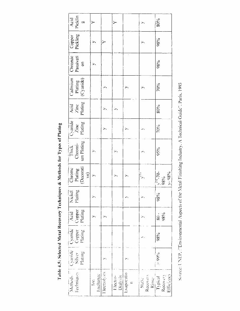
Tab
le 4
.5:
Sel
ecte
d M
etal
Rec
over
y T
echniq
ues
& M
ethods
for
Types
of
Pla
ting
Met
hod
T C
v<"1
nide
Cya
nide
Aci
dN
icke
lC
hrom
eT
hick
Cya
nide
Aci
dC
adm
ium
Chr
omic
Cop
per
Aci
d[c
chni
gnc
ilve
rC
oppe
rC
oppe
rP
lati
ngP
lati
ngC
hrom
i-Z
inc
Zin
cP
lati
ngP
assi
vati
Pic
klin
gP
ickl
inPl
atin
g.
Pla
ting
Pla
ting
(Dec
orat
ium
Pla
ting
Pla
ting
Pla
ting
(Cya
nide
)on
gve
)
^—
!on
y`
yy.
YY
YE
acha
-n-c
laec
trc,
l:is
yy
yy
yY
Eiec
tro
yy
yY
Dia
ls'iS
Stat
SIIO
C.__
iy
v^;,
)'y
yY
yR
ecd' N
\R
inse
T^ p
ical^>
99°
/o98
%80-
98%
y)-7
0-95
%70
%80
%70
%98
%98
%80
%R
eco\
e'98
%98
%E
f lc
ICn
c\
Sou
rce:
I.
NE
P. "
Envir
onm
enta
l A
spec
ts o
f th
e M
etal
Fin
ishin
g I
ndust
ry. A
Tec
hnic
al G
uid
e`. P
aris
. 1993

Chapter 5
Waste Minimisation & Treatment to Control Pollution
5.1 General
Electroplating generates all three forms of waste -- liquid, gaseous and solid. Of these.liquid wastes are predominant. Such liquid wastes include : (i) spent chemicals andsolutions such as acids, alkalies, cleaning agents, bath chemicals comprising platinoochemicals as well as additives such as brighteners. levellers etc. and rinse waters. whichmay contain some or all of these depending upon sources, method of plating andhousekeeping practices.
Gaseous wastes include solvents and vapours from hot pre-treatment and process bath;.They include acid alkali mist, Volatile Organic Compounds (VOCs). In some cases. mistsand VOCs may contain metals in addition to process chemicals. Accordino to oneestimate, approximately 30% of the solvents and degreasing agents used can he releasedas VOCs when baths are not regenerated.
Solid wastes include, sludges generated from wastewater treatment. diidge,., frc wcleaning and bath tanks and various residues like, cleaning powder. buffin ' compound s .spent anodes and various scraps. Unused chemicals, spent resins frons icon-exchangemetal recovery systems also contribute to solid waste. Much of the solid vvaste containhazardous and toxic substances.
Waste minimisation therefore occupies the most important position in the ,oll ros i !pollution from electroplating and overall protection of the recipient environment \a h
air and land (soil).
5.2 Waste Minimisation & Process Modification
Waste minimisation in an Electroplating unit may include any one. combination or all ofthe following:1. Minimisation of Wastewater GenerationThis is the single most significant step towards waste minimisation. The results of the in-depth study points to an immediate need towards this objective. While the large andorganised units practice full or partial wastewater minimisation. small scale and tiny unitsdo not do anything at all. Numerous studies reported in literature also point out to se' cralapproaches, which can be briefly stated as;• Introduction of rinse water recirculationwith automatic benefit of chemical recovery
and reuse• Static rinse water recovery• Avoiding and controlling spillage — single largest cause of high wastewater
generation in the unorganised sector. By using troughs between tanks and using welldefined linear configuration in place of barrels and avoiding haphazard rinsing andwashing will ensure very significant reduction in quantum of wastewater generated.
49
• Introduction of cascade and/or counter- current rinsing• Use of fogging and spraying on objects (rack plating)• Introduction of metal recovery by electrolytic method (ion-exchange and its advanced
application leading to high recovery ratio of water (upto 80%).Analyses of cost saving by metal recovery using ion-exchange process indicatethat for a small scale plant @ 2.5 kg Chromic acid per day and 2.5 kg NickelSulphate per day, gross saving would be Rs. 1.01 lakh and 1.20 lakh per year.For large plants @ 2.5 kg Nickel Sulphate per hour, the saving by advanced ion-exchange would be Rs.37.64 lakhs per year.
2. Minimisation of Gaseous Emission
Except a few states (e.g., Karnataka and Maharashtra), State Pollution ControlBoards do not generally require electroplating units to provide any measure forelimination or control of gaseous emission. As discussed earlier, gaseous emissiontakes place as vapours from hot baths, normal evaporation from cold baths do notconstitute significant source of such emission and VOCs from organic cleaning baths.
Use of collecting hoods and scrubbers can significantly control or eliminate vapoursfrom baths. Collecting arrangements have improved substantially but older plantseither have no collecting hoods or only side suction arrangement, which are noteffective at all. Completely covered baths are ideal solution but they are useful incompletely automated plants as used in Europe and parts of North America. Howeveruse of top suction hoods with properly designed scrubber system certainly controlsmuch of the gaseous emission. As far as emission of VOCs are concerned, idealsolution is not to use those with high environmental concerns (discussed in Section4); even if they are used, the best practice is to keep the tanks fully covered at alltimes and using vapour arresting devices.
3. Minimisation of Solid Waste
Major part of solid waste (that too, hazardous) is sludge from waste water treatmentplant. Therefore, if measures are taken to minimise waste water generation byadopting methods stated in sub -para I above, waste water sludge generation isminimised. Other constituents of solid waste are: (1) spent anodes, (ii) tank sludges,(iii) spent carbon filters and (iv) empty containers of chemicals etc.. The last-namedone is usually sold to scrap dealers. Tank sludges and spent carbon filters maycontain hazardous metal salts. While the quantity depends on production, disposalpractices should conform to regulatory requirements pertaining to hazardoussubstances. Therefore using non-hazardous chemicals will lead to minimisation ofhazard in solid waste from process chemicals. Use of Cyanide free process (e.g.Alkaline Cyanide Free Zinc plating), use of trivalent Chromium in place ofhexavalent Chromium are examples of such hazard minimisation.
50
4. Minimisation of Noise Emission
Plating activity by itself does not produce significant noise, except barrel plating ofsmall obhects. Major source of noise is operation of air blowers used for blowing airin plating (for Nickel Plating) and in pre-cleaning operations . Such noise isminimised by putting the air blower in a separate room with noise mufflingarrangements. In many plants and factories, it was observed that high ambient noiselevel in plating areas is caused by activities other than electroplating such asmachining, stamping, .metal forming, forging, etc. etc. Noise reduction in suchactivities is however, outside the purview of this study.
5.3 Best available Technology (BAT)
5 .3.1 General
The Best Available Technique (BAT) means the most effective and advanced stage in thedevelopment of' activities and their methods of operation, which indicate the practicalsuitability of particular techniques for providing in principle the basis for minimumemission values designed to prevent and, where it is not practicable, generally to reduceemissions and the impact on the environment as a whole.
Techn quel include both the technology used and the way in which the installation isdesigned, built, maintained, operated and decommissioned, including also training.Available techniques means those developed on a scale which allows implementation inindustrial sector under economically and technically viable conditions, taking intoconsideration the costs and advantages. Best means most effective in achieving a highgeneral level of protection of the environment as a whole.
The objective of the BAT Guidelines is to provide a list of techniques. includingtechnologies, which will provide guidance to the local regulatory bodies and theindustries when determining BAT for an activity. 'i'he BAL' identified in this Report isintended to control and/or minimise pollution and improve the environmentalperformance by incorporating the technological advances as they occur.
In the identification of BAT, emphasis is placed on pollution prevention techniques,including cleaner technologies and waste minimisation, rather than end-of-pipe treatment.Consideration should be given to energy efficient technologies and practices and toefficient use of raw materials, chemicals and water. Whenever economically andtechnically feasible, dangerous substances should be substituted by less dangerous ornon-dangerous substances. Measures such as in-plant changes, process recycling andimproved material handling and storage practices may also be employed to eftcctreduction in emissions.
"l'he guidance issued in this note in respect of the use of' any technology, technique orstandard does not preclude the use of any other similar technology, technique or standard,which may achieve the same emission. The entire range would not necessarily be
51
appropriate in specific cases. The specific choice depends on a wide range ofcircumstances but the crucial factor is that the selected regime achieves BAT. Whendeciding the technology, local Ambient Quality Norms must he taken into consideration.
In addition to providing for the installation of equipment and the operation of proceduresfor the reduction of possible emissions, BAT will also necessitate the adoption of an on-going programme of environmental management and control, which will focus oncontinuing improvements aimed at prevention, elimination and/or progressive reductionof emissions.
When determining best available techniques generally or in specific cases, bearing inmind the likely costs and benefits of a measure and the principles of precaution andprevention, account must be taken of:
1) the use of low-waste technology,2) the use of less hazardous substances,3) introduction of recovery and recycling of substances generated and used in the
process and of waste, where appropriate,4) comparable processes, facilities or methods of operation which have been tried with
success on an industrial scale,5) technological advances and changes in scientific knowledge and understanding,6) the nature, effects and volume of the emissions concerned,7) the commissioning dates for new or existing installations,8) the length of time needed to introduce the best available technique,9) the consumption and nature of raw materials (including water) used in the process
and their energy efficiency,10) the need to prevent or reduce to a minimum the overall impact of the emissions on
the environment and the risks to it,11) the need to prevent accidents and tominimise the consequences for the
environment;
The techniques are regarded as representing BAT for a new activity. However, it is alsogenerally intended that existing facilities will progress towards attainment of similaremission standards (ES). but the specific ELV requirements and associated time frameswill be identified on a case by case basis when the consent application is being processed.
Furthermore, for all facilities, additional and more stringent requirements may bespecified on a site-specific basis whenever environmental protection so requires. Hencethe BAT guidelines are not the sole basis on which consents are to he granted, sinceinformation from other sources and legal Acts will also be considered. including site-specific environmental and technical data. and other relevant information.
5.3.2 Best Available Technique -Solutions (BATs)
52
In order to avoid unwanted adverse impact on the environment from the plating activities,various abatement measures can he adopted. While many industrial units may havealready implemented various solutions. To a large extent these solutions can be referredto as conventional solution.
The fundamental approach in achieving BAT involves following important
considerations.
• all wastes are to be considered as unused raw materials although a completenon-waste solution is not realistic
• BAT might be applied in the three key areas- good housekeeping practices involving working habits and attitudes- technical modification involving modifications on existing machinery,- process modification involving substitution of' chemicals and
alternative processes
• BAT might be applied at different levels of sophistication:Immediate application : applying low-tech measuresIntermediate application : applying medium-tech measuresAdvanced application : applying high tech measures
• BAT measure(s) might he applied progressively i.e. singly or in combinationas some measures require:- no significant or little investment but need more organised working.
cleaning and better supervision with maintenance while- other measures needing considerable investment in the form of additional
equipment
BAT might result in:
• reduction in resource consumption of:- water- chemicals- energy (electricity)
• reduced amount/emission of:- wastewater- containing, chemicals.
sludge and other waste typesair emission
• improved bottom line in terms ot- reduced production costs- improved product quality- credibility and competitiveness
53

4.3.3 BAT benefitsThe following benefits might be expected:• Minimised risk of pollution in event of accidents• Minimised chemical exposure of employees• Minimised consumption of chemicals and water• Improved personnel morale due to healthier and safer work environment• Production-downtime prevention or reduced scrap production caused by
improper choice of materials, insufficient programming facilities, badmaintenance of equipment or bad configuration of the processes
5.3.4 General BAT approachSome general BAT measures, which are relatively simple and easy to adopt aresummarized below.
Table 4.1: Examples on general BAT measures within electroplating
General (P Measures Method Benefit
• Cleaning and Improve cleaning and Reduce consumption of chemicalsmaintenance Maintenance and energy (heat and electricity)
• Appropriate storage-----------------------------------------------------
Have paved and sheltered storage Minimise risk ofof ch mical drums with drums stacked not more than - chemical contamination 0) soil
3 tiers and to allow free movement - spillage onto floorof the fork lifl
• Insulate hot process-----------------------------------------------------
Use chemical resistant material Reduce heat losses
tanks including piping
• Maintain chemical-----------------------------------------------------
Use conductivity meters to know - Avoid chemical depletionconcentration in when to top up chemicals due to - Prevent overdose of chemicalsplating baths at Depletionoptimum level
• Introduce drip guard-----------------------------------------------------
Use chevron shaped deflectors to - Avoid spillage onto the floorbetween adjacent return drag-out of chemicals/liquid - Recovery of chemical drips backtanks hack to the relevant tanks into relevant tanks
• Replace worn-out - - - - Use plastic tanks which are - - - - - - Prevent chemical leakage - - - - - -tanks and leaky pipes resistant to corrosion - Reduce water consumption
Increase Iii span of'tanks
• Spray rinsing in small-----------------------------------------------------
Install water pipe with spray - Reduce consumption of water
pulses nozzles over the rinsing tanks - Reduce metal drag-outwherein work pieces are sprayedduring hoisting
• Rotate plating barrels---- -----------------------------,-------------------
Use auto controller to effect the Shake oil drag-outat top position Rotation
• Adopt multiple-----------------------------------------------------
Use, for instance. air-lift pumps for - Reduce drag-out of
counter-flow rinsing hack-filling to previous rinsing tank chemicals/liquidand back-filling to with : - Save use of fresh waterplating bath - inlet at the top and - Less cross contamination
- outlet at the bottom between tanksPre-condition for back-filling is use of
54
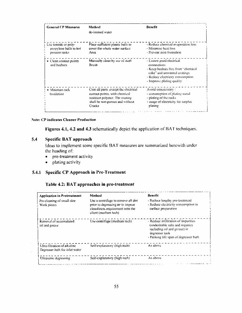
General CP Measures Method Benefit
de-ionised water
Use tenside or poly------------------------------------------------------
Place sufficient plastic balls to Reduce chemical evaporation losspropylene halls in hot cover the whole water surface - Minimise heat lossprocess tanks Area - Prevent mist formation
• Clean contact points-------------------------------------------------
Manually clean by use of steel-----^
- Ensure good electricaland busbars Brush connections
Keep busbars free from "chemicalcake"' and unwanted coatingsReduce electricity consumptionImprove plating quality
• Maintain rack------------------------------------------------------
Coat all parts .except the electrical Avoid unnecessary
Insulation contact points, with chemical - consumption of plating metalresistant polymer. The coating - plating of the racksshall be non-porous and without - usage of electricity for surplusCracks plating
Note: CP indicates Cleaner Production
Figures 4.1, 4.2 and 4.3 schematically depict the application of BAT techniques.
5.4 Specific BAT approach
Ideas to implement some specific BAT measures are summarized herewith underthe heading of:• pre-treatment activity• plating activity
5.4.1 Specific CP Approach in Pre-Treatment
Table 4.2: BAT approaches in pre-treatment
Application in Pretreatment Method Benefit
Pre-cleaning of small size Use a centrifuge to remove all dirt - Reduce lengthy pre-treatmentWork pieces prior to degreasing or to impose - Reduce electricity consumption in
cleanliness requirement onto the surface preparationclient (medium tech)
---------------------------------------------------------
Removal of accumulated Use centrifuge (medium tech) - Reduce infiltration of impuritiesoil and grease (undesirable salts and organics
including oil and grease) indegreaser tankProlong life span of degreaser bath
---------------------------------------------------------
Ultra-filtration of alkaline Self-explanatory (high tech) As aboveDegreaser bath for inlet water
---------------------------------------------------------
Ultrasonic degreasing Selt. explanatory (high tech) As above
55

Ele
ctro
pla
tin
g W
ork
Ste
p 1
:F
ig. 4
.1
Ele
ctro
pla
tin
g P
re-t
reat
men
t -
BA
T a
pp
roac
h
L

Ele
ctro
pla
tin
g W
ork
Ste
p 2
:F
ig. 4
.2
Pla
tin
g O
per
atio
n -
BA
T a
pp
roac
h f
or N
ick
el &
Ch
rom
ium
Pla
tin
g

C
E
0
Uca
N 0fl.C: iV
. 0
D V0á
Ó (
W Q
C0
I-
C)C.0
C
0i7
bQ.r,
58
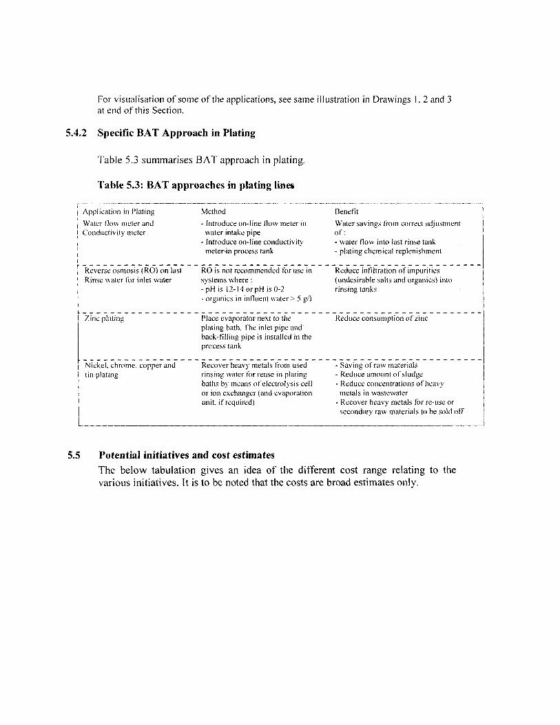
For visualisation of some of the applications, see same illustration in Drawings 1,2 and 3at end of this Section.
5.4.2 Specific BAT Approach in Plating
Table 5.3 summarises BAT approach in plating.
Table 5.3: BAT approaches in plating lines
Application in Plating Method
Water flow meter and Introduce on-line flow meter inConductivity meter water intake pipe
Introduce on-line conductivitymeter-in process tank
Benefit
Water savings trom correct adjustmentof- water flow into last rinse tank- plating chemical replenishment
----------------------------------------------------------Reverse osmosis (RO) on last RO is not recommended for use in Reduce infiltration of impuritiesRinse water for inlet water systems where : (undesirable salts and organics) into
pH is 12-14 or pH is 0-2 rinsing tanksorganics in influent water> 5 gIl
----------------------------------------------------------Zinc plating Place evaporator next to the Reduce consumption of zinc
plating bath. The inlet pipe andback-filling pipe is installed in theprocess tank
----------------------------------------------------------Nickel, chrome, copper and Recover heavy metals from used - Saving of raw materialstin plating rinsing water for reuse in plating - Reduce amount of sludge
baths by means ofelectrolysis cell - Reduce concentrations of heavyor ion exchanger (and evaporation metals in wastewaterunit, if required) - Recover heavy metals for re-use or
secondary raw materials to be sold off
5.5 Potential initiatives and cost estimatesThe below tabulation gives an idea of the different cost range relating to thevarious initiatives. It is to be noted that the costs are broad estimates only.
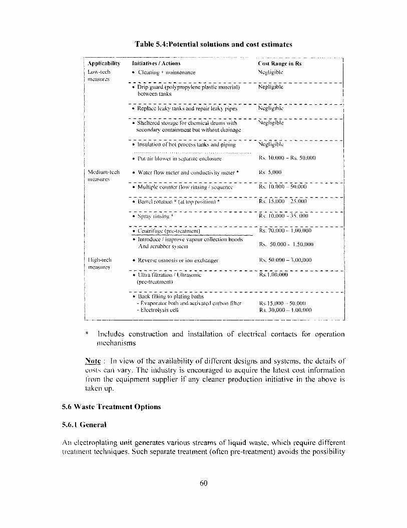
Table 5.4:Potential solutions and cost estimates
Applicability Initiatives / Actions Cost Range in RsLow-tech • Cleaning + maintenance Negligiblemeasures
-------------------------------------------
• Drip guard (polypropylene plastic material) Negligiblebetween tanks
-------------------------------------------
• Replace leaky tanks and repair leaky pipes Negligible
-------------------------------------------• Sheltered storage for chemical drums with Negligible
secondary containment but without drainage
-------------------------------------------
• Insulation ol'hot process tanks and piping.............................................................
Negligible
• Put air blovaer in separate enclosure R. 10.000 - Rs. 50.000
Medium-tech • Water flow meter and conductivity meter * Rs. 5.000measures
-------------------------------------------
• Multiple counter flow rinsing / sequence Rs. 10.000 - 50.000
--------------------------------------------• Barrel rotation * (at top position) * Rs. 15.0011 25.000
-------------------------------------------• Sprak rinsing, Rs. 10.000 - 35. 00O
-------------------------------------------• Centrifuge (pre-treatment) Rs. 70.000-- 1.00.000
• Introduce / improve vapour collection hoodsAnd scrubber system Rs. 50.000 - 1.50,000
High-tech • Reverse osmosis or ion exchanger Rs. 50.000 - 3.00.000measures
-------------------------------------------
• Ultra filtration / Ultrasonic Rs. 1.00.000(pre-treatment)
-------------------------------------------
• Back filling to plating bathsEvaporator bath and activated carbon filter Rs. 15.000 -- 50.00OElectrolysis cell Rs. 30.000 -- 1.00.000
Includes construction and installation of electrical contacts for operationmechanisms
Note : In view of the availability of different designs and systems, the details ofcosts can vary. The industry is encouraged to acquire the latest cost informationfrom the equipment supplier if any cleaner production initiative in the above istaken up.
5.6 Waste Treatment Options
5.6.1 General
An electroplating unit generates various streams of liquid waste, which require differenttreatment techniques. Such separate treatment (often pre-treatment) avoids the possibility
60
of mixing incompatible wastes, which makes treatment difficult, expensive and lessreliable. Often such mixing can be a hazard to personnel or formation of complexes thatare difficult to treat, such as mixing of Nickel plating wastewater with Cyanide bearingwastewater leading to formation of Nickel Cyanide. Therefore, segregation of wastewaterstreams is of paramount importance. During the in-depth study, it has been noted that inmajority of small-scale and tiny units, this is just not done , indicating an urgent need tointroduce this basic requirement.
As a general rule, waste streams and characteristics must be carefully evaluated beforeselecting a treatment scheme. It was found during the study that units in large andmedium scale have opted for treatment schemes that cater for their particular wastes,although there is a commonality of treatment methods and/or processes used. In somecircumstances, (e.g., in Bangalore),. it is found to be economical, practical and muchbetter managed to have a centralized vaste treatment facility operated by a separateentity. In fact it is a welcome development that in many states, industrial estates andparks are coming up to shift existing units and accommodate in a properly organisedgroup of electroplating units with a Clfl'P (example Faridabad in Haryana; Madurai inTamil Nadu, Anand Parbat area in Delhi etc.)
5.6.2 Principles of Treatment
For most heavy metals, precipitation as insoluble hydroxy or sulphite compounds isachieved by addition of simple reagents followed by pli adjustment and sedimentation. Inthe case of hexavalent Chromium, it is necessary to First chemically reduce the metal totrivalent state and then form insoluble precipitates. However for certain very hazardousheavy metals such as Cadmium, a totally separate system may be advantageous,including separate disposal procedures.
Where the wastewater contain cyanides, removal of' cyanides is achieved by oxidation toharmless residues, followed by a precipitation step to remove accompanying solublemetal ions.
It is important. to distinguish between treatment of' rinse water (high flow and lowconcentration) and discarded strong process solutions (cleaners, acid dips, platingsolutions etc.) of low volume and only occasional discharge but of high concentration.Clearly, a batch treatment system would cope with two types of wastewater rather than acontinuous flow system which is likely to be upset by shock loads. The guiding principleis to store such strong wastes and release them gradually into treatment system. Thusflow equalisation is animportant operation to integrate into the treatment system.
5.6.3 Treatment Processes
5.6.3.1 Treatment of Hexavalent Chromium bearing wastewater.Hexavalent chromium compounds come from processes such as polishing andbrightening, pickling, passivation, chrome plating and plastic metallisation. Reduction of
om
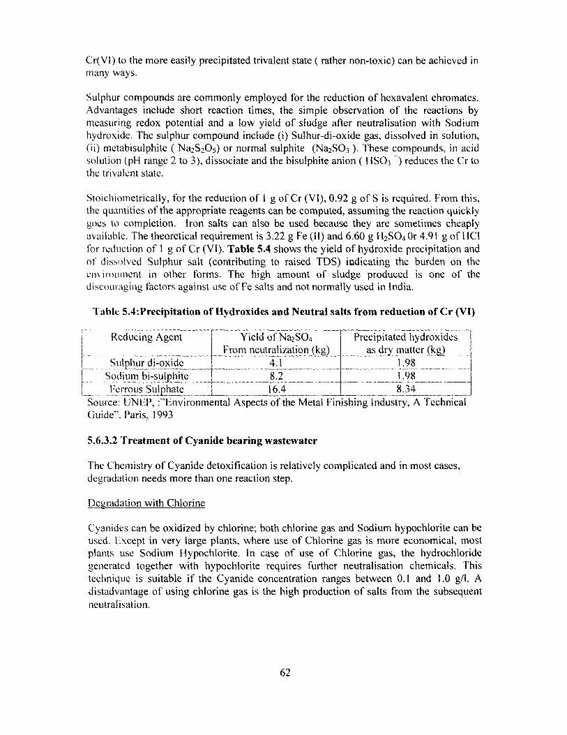
Cr(Vl) to the more easily precipitated trivalent state ( rather non-toxic) can be achieved inmany ways.
Sulphur compounds are commonly employed for the reduction of hexavalent chromates.Advantages include short reaction times, the simple observation of the reactions bymeasuring redox potential and a low yield of sludge after neutralisation with Sodiumhydroxide. The sulphur compound include (i) Sulhur-di-oxide gas, dissolved in solution,(ii) metabisulphite (Na2S2O5) or normal sulphite (Na2SO3 ). These compounds, in acidsolution (pH range 2 to 3), dissociate and the bisulphite anion (1-I SO; ^) reduces the Cr tothe trivalent state.
Stoichiometrically, for the reduction of 1 g of Cr (VI), 0.92 g of S is required. From this,the quantities of the appropriate reagents can be computed, assuming the reaction quicklygoes to completion. Iron salts can also be used because they are sometimes cheaplyavailable. The theoretical requirement is 3.22 g Fe (11) and 6.60 g H2SO4 Or 4.91 g of 1-ICIfor reduction of 1 g of Cr (VI). Table 5.4 shows the yield of hydroxide precipitation andof dissolved Sulphur salt (contributing to raised TDS) indicating the burden on theenvironment in other forms. The high amount of sludge produced is one of thediscouraging factors against use of Fe salts and not normally used in India.
Table 5.4:Precipitation of Hydroxides and Neutral salts from reduction of Cr (VI)
Reducing Agent Yield of Na2SO4 Precipitated hydroxidesFrom neutralization (kg) as dry matter (kg)
Sulphur di-oxide 4.1 1.98Sodium bi-sul hite 8.2 1.98Ferrous Sul hate 16.4 8.34__
Source: UNEP, :"Environmental Aspects of the Metal Finishing Industry, A TechnicalGuide". Paris, 1993
5.6.3.2 Treatment of Cyanide bearing wastewater
The Chemistry of Cyanide detoxification is relatively complicated and in most cases,degradation needs more than one reaction step.
Degadation with Chlorine
Cyanides can be oxidized by chlorine; both chlorine gas and Sodium hypochiorite can beused. Except in very large plants, where use of Chlorine gas is more economical, mostplants use Sodium Hypochiorite. In case of use of Chlorine gas, the hydrochloridegenerated together with hypochlorite requires further neutralisation chemicals. Thistechnique is suitable if the Cyanide concentration ranges between 0.1 and 1.0 g/l. Adistadvantage of using chlorine gas is the high production of salts from the subsequentneutralisation.
62
When Sodium Hypochlorite is used, there is a two step process. In the first step, cyanidesare oxidised by hypochlorite to cyanogen chloride, which is an extremely toxic gas. Thesecond step, which takes place almost simultaneously, involves hydrolysis of cyanogenchloride to cyanate. The latter is highly soluble in water but care should be taken toensure that the temperature does not exceed 40 0 C, so that degassing does not take place.Hazards are best minimized by ensuring as rapid a hydrolysis as possible. This isachieved at a high pH of around 1 1.5 with a detention time of upto I hour to guaranteecomplete reaction. Good mixing is essential. In some countries the retention time may beset by regulation. In most cases found during the in-depth study, further oxidation fromCyanate to Nitrogen and Carbon is not carried out and the effluent is sent to anequalisation tank for neutralisation. Where further oxidation is required, it is carried outby using Sodium Hypochlorite again at a pH of 8.0 to 8.5. It is very important to havecorrect and reliable pH control to prevent toxic gas formation under acidic conditions.
Degradation with Active or Activated Oxygen
Oxidation of Cyanides directly using oxygen leads to a great benefit that no salts areproduced and no neutralisation of solution is required. This can be done by using (i)Hydrogen Peroxide, (ii) Persulphuric Acid and (iii) catalytic oxidation.
Theoretically, 1.3 kg 11202 is sufficient per kg of cyanide. However, in practice. (a)excess 1-1,02 is required to ensure complete reaction and (b) this process is notrecommended with low initial cyanide concentration i.e., less than 500 mg/l.. Addition ofcatalysts or Formic acid accelerates the reaction, enabling the method suitable for use inthe concentration range of 100 to 1000mg/I.
Persulphuric acid is often used as Oxygen delivering substance. It hydrolyses to I (,O , andsulphuric acid in aqueous solution. Direct ozonation is another available method.Conentrated peroxides and persulphates are hazardous substances and should be dealtwith accordingly.
Electrolytic Process
When the cyanide waste is concentrated, an economical solution for degradation iselectrolysis in presence of chlorides. Cyanides can be oxidised by electrolytic splitting ofoxygen from hydroxides.
Precipitation of Cyanides
Iron ions form highly stable complexes with cyanides. A precipitation of divalent ortrivalent hexacyanoferrates is possible as a detoxification step within the final wastewatertreatment. But the resulting sediment is not fit for disposal to a landfill site , becauseacids or photolytic reactions may, under certain circumstances, release cyanides from theresidue. Such sediments can be subjected to thermal destruction.
b3

Comparison of Methods
The popular detoxification method for cyanides in small metal finishing plants is stilloxidation by chlorine. Advantages are the speed of reaction, easier process control, lowcosts and a relatively long experience in handling.
For concentrated wastes, precipitation as hexacyanoferrates is suitable but must befollowed by thermal degradation.
Peroxy- compounds have the general disadvantage of long retention times. Theseprocesses are useful only where small quantities of cyanide bearing wastewaters are to betreated. The content of salts in the effluent is low.
in summary, if cyanides are destroyed in in a continuous flow stream, hypochloritetreatment may be the best choice because of its simple handling and other advantages asmentioned before. if concentrated or small volumes are to be treated, techniques shouldbe chosen which yield a minimum of waste even if'performance and maintenance is morecomplex.
5.6.3.3 Neutralisation and Precipitation
This principal operation in the wastewater treatment is intended to convert dissolvedmetals to insoluble hydroxides and removed from the effluent. The operation is precededby flow equalisation as an essential step. The precipitation chemicals used are SodiumHydroxide, Lime and Soda. Magnesium hydroxide is sometimes used but the reaction isslower and pH range is limited. Alkaline wastewaters are neutralized by sulphuric acidbut it has a constraint for sulphate limits, if set as effluent standard. Smaller facilities useSodium Hydroxide solution (450 g/I). 1-Iowever. if the wastewater contains fluorides.Lime solution should be used. Lime solution is cheaper and used by larger units. A limesolution preparation unit is required in the latter case.
The maintenance of correct pH is essential for efficient precipitation of metal hydroxides.Fig 5.4 shows the pH ranges for precipitation of several metal hydroxides. For mostcases, pH would be in the range of 8.5 to 1 1. Unnecessary high pil may interfere with theformation of a good settleable sludge. Therefore, the best practice is to maintain a Pl - 'slightly above minimum pH value. Further adjustment may be required in case of specificeffluent standard.
5.6.3.4 Design & Costing of a Typical Wastewater Treatment Plant
Based on the treatment techniques discussed above, a typical wastewater treatment plantfor a unit doing Cr/Ni plating and a little Zn plating using Cyanide Zn process can bedesigned and cost estimates made. The capital cost of such a unit is estimated at Rs. 2.16lakhs. The operation & maintenance cost is estimated at Rs. 1618 per day or
64

Fig
ure
8.4
: R
ange
of
pH
for
Pre
cipit
atio
n o
f M
etal
Hydro
xid
es
C vi

approximately at Rs. 4.85 lakhs. The cost per kl comes to about Rs. 46 per kl, which isconsidered rather high as compared to Unit J, privately run CETP. It is interesting to notethat cost of chemicals alone accounts for 86 -- 88% of total operating cost. Clearly, thispoints out to the need to minimise water and chemical consumption and introduce metalrecovery.
5.7 Hazardous Wastes Rules
According to the Hazardous Waste (Management and Handling) Rules, 2002 and asamended vide S.O. 593 (E) dated 2oth May, 2003, the following wastes fromElectroplating Industry are identified and listed in Schedule 1 of the said rules
I. Acid Residues2. Alkali Residues3. Spent bath/sludge containing sulphide, cyanide and toxic metals4. Sludge from bath containing organic solvents5. Phosphate Sludge6. Sludge from staining bath7. Copper etching residues8. Plating metal sludge9. Chemical Sludge from wastewater treatment
In the following paragraphs, salient features of the rules are mentioned. For completeinformation, the reader may refer to the original rules and amendments vide the Gazetteof India (extraordinary) part II, section 3 (ii), in which the notification dated 20` x' May2003 has been published.
5.7.1 Responsibility of Waste Generator (occupier)
According to the provisions of the rules, every occupier of an industrial unit or wastegenerator shall obtain authorization from the concerned State Pollution Control Board orCommittee to handle, treat, store and dispose off such hazardous wastes. For thispurpose, the occupier (industrial unit generating waste) shall submit information in adesignated Form No. 1 to seek authorization. The authorization would be valid forstipulated period and renewal must be sought. Furthermore, the unit shall also submit anannual return to the concerned State Pollution Control Board or Committee in thedesignated Form 4.The occupier shall take all practical steps to ensure that such wastes are properly handledand disposed off without any adverse effects which may result from such wastes. Ile shallalso be responsible for proper collection, reception, treatment, storage and disposal ofthese wastes either himself or through the operator of a facility.
5.7.2 Transport of Hazardous Waste
In case of transport of hazardous wastes to a facility for treatment, storage and disposal,the rule also provides for procedures to be followed by the waste generator, transporter,operator of the facility and the State Pollution Control Board/ Committee. "Storage".
66
however means storing hazardous wastes for a temporary period, at the end of which thehazardous waste is treated and disposed off.
5.7.3 Disposal of Hazardous Waste
As far as the Disposal facility is concerned, the industrial unit not having a hazardouswaste treatment and disposal facility of his own, shall send wastes to a commonTreatment. Storage and Disposal Facility (TSDF). He shall also become a member ofsuch facility.
The onus of setting up of a common TSDF rests with the State Pollution Control Boards,although the rule stipulates that " the occupier or operator of a facility or any associationof occupiers shall be jointly and severally responsible for identifying sites for establishingthe facility for treatment, storage and disposal of hazardous wastes". Procedures areclearly laid down how to identify a site and set up a facility.
To ensure transparency and accountability of the State Pollution Control Board(s)/Committees, the rule stipulates that such boards or committees shall prepare aninventory of hazardous wastes and compile information related to treatment & disposal.Furthermore, every State Pollution Control Board (s)/Committee shall maintain a registerproviding particulars of disposal on any land or premises and such register shall be openfor inspection to any person interested or affected.
5.8 Housekeeping Guidelines
Although good housekeeping is a matter of attitude, particularly the attitude ofmanagement and shared by the workforce, it is more of a necessity than an option in anindustry like electroplating. Many of the chemicals used are hazardous and toxic, there isgood potential of accidents to occur and the industry poses threats of adverse impacts onthe natural environment. These factors lead to a great need for good housekeeping. inorder to ensure health and safety of all working personnel as well as the public at large.The housekeeping can be subdivided into three main topics: (a) storage and handling ofchemicals (b) housekeeping in production shop floor i.e., pre-cleaning and platingoperations and (c) housekeeping of rejects and wastes. In order for housekeeping to beeffective and routinely carried out, the following are essential:
• Management accepting its lead role in providing safe working conditions andprocedures.
• Participation by the workforce in ensuring safety at work• Clear allocation of responsibilities for safety and health services• Safety training and instruction, on induction and on-going• Reporting, investigation and analysis of accidents and working conditions• Dissemination of information on hazards and risks• Co-operation with labour and safety instructions and reviews
67

In the following paragraphs, brief guidelines are given for better housekeeping;
5.8.1 Storage and Handling of Process Chemicals
Process chemicals consist generally of (a) acids, (h) alkalies (c) cleaning agents (d) metalsalts for preparation of bath solutions (e) additives and (f) anodes. The basic guidelinesare:I. Acids and alkalies should be stored separately2. Containment bonds should be provided on floor to containn accidental leakage or
spills3. Volatile organic compounds should be stored in gas tight containers and kept under
lockable covered sheds4. Only authorized personnel shall have access to these materials. These personnel
should be made aware of material characteristics through training; Material SafetyData Sheets (MSDS) should be displayed at a prominent location.
5. Training to provide aid during accidents and spills should be given to designatedpersonnel, whose names and contact details should he displaced at prominentlocations
6. Wherever possible, solution preparation should he done in lined tanks/containersand transferred to process baths by pumps only.
5.8.2 Housekeeping in Production Shop Floor
This aspect is by far the most important activity in the day-to-day running of anelectroplating plant. Good housekeeping will ensure smooth production. encouragementto personnel and developing a positive :ittitude among all. These can he generallysummarised as:1. Avoid clutter and untidy working condition. Introduce floor marking to designate
areas for material storage, movement of personnel and handling equipment such aspallet trucks and worker stations, control panels and so on.
2. F;nsure that floor should always be dry, non-slippery and clean;. Provide curbing and channels to accommodate valve gland leaks and overfow-s,
condensates and drainage and lead them to designated holding and/or equalisationtanks for treatment and/or recovery
4. No rinse-water or drag-outs should spill on the floor the most important item totallyignored in small and tiny units across the country
5. A holding pit should be provided to arrest accidental spills or leakages on shop floor,sloped towards it.
6. Floor should be kept clean and free of obstacles for unhindered movement ofpersonnel.
7. While filling or topping up tanks/ baths, care should he taken to prevent overtlows-usc following techniques:• Fit hoses with spring loaded nozzles• Use metering pumps to accurately translcr required quantities, where feasible• Where water is added directly from piping, use float level controls• Install backflow- preventers, where water is discharged below solution surface
68
• Supervise regularly and keep records of all such operations, indicating overflows,and losses, spills etc, whatever occurs.
8. Regularly check all alarms, control devices and meters/recorders as permanufacturer's advice
9. Check all metal protection such as tank lining, painting on railings, piping. chains andhoists and electrical/piping racks against signs of corrosion. A timely interventionsaves lot of expensive repairs, shutdowns and avoidable accidents.
5.8.3 Housekeeping of Rejects and Wastes
Rejects and Wastes generated in Electroplating wastes include the following:• Process waters of various kinds• Spent process solutions and electrolytes• Surplus chemicals• Empty containers, packing materials• Scraps of various kinds• Sludges and filter cakes
Process Water, Spent Process Solutions and Surplus Chemicals
The detailed considerations for the first three have been discussed in Chapter 4 and Sub-sections 5.1 through 5.4. However, general guidelines can be summarised as under:
1. All process wastewater should be segregated according to their characteristics2. Wherever feasible, recovery of metals and other chemicals should he recovered
care being taken to ensure undesirable salt content do not rise in recycledsolutions
3. Flow equalisation tanks must be provided before treatment of various streams andin each unit operations
4. For very small wastewater flow, it is advisable to haul wastewater to a commontreatment facility,
5. Tanks, piping, valves, filters shall be of corrosion resistant materials andleakproof. Arrangement should be provided to arrest leakages by channels andcurbings and brought to holding tanks/equalisation tanks lor furthertreatment/disposal.
6. Surplus chemicals not meant for use or return to vendor, should be diluted anddischarged slowly into appropriate stream of' wastewater; they should not hedisposed of by discarding them into general waste bins or ri'ashing lhenr down thedrain unless speel lical permitted_by regulatory authorities
7. l la ardour chemicals and wastes shall be disposed through licensed contractor
69
Empty Containers, Packing Materials e tc.
Since many chemicals used in electroplating are toxic, there is good chance that virtuallyanything coming in contact with operations can be contaminated. Good housekeepingwill ensure that this will not be the case and if contamination occurs, they should be de-contaminated or disposed properly. The following may be noted:
1. Tools and equipments should be kept only in designated area and not leftelsewhere
2. Separate waste bins for different kinds of waste should be used with clearlabelling and workers trained to use them
3. If empty containers are used as waste bins, it should be first thoroughlycleaned and all previous markings pbliterated and /or painted over
4. Containers of toxic and hazardous chemicals should not be used for otherstorage; they should be disposed as per manufacturer's instructions
5. All materials that are contaminated with chemicals can be considered to betoxic as safety measure and treated accordingly.
Sludges and Filter Cakes
Disposal of sludges is now one of the major environmental concerns for theelectroplating industry. Because of heavy metal content, sludges from wastewatertreatment plants are considered hazardous. Many countries including India haveregulations concerning handling, storage and disposal of such hazardous materials.
Based on the findings of the in-depth study, it was noted that in many areas irrespectiveof the state, centralised sludge disposal facility has not been built by the State PollutionControl Boards. In such cases, the industry has been asked to organise safe storage for aspecified period. The following guidelines may be useful in this regard:
I. Sludges should be compressed and dewatered to reduce volume as much aspracticable
2. They then should be poured in PE bags, sealed and labelled or tagged withdate, quantity and description of content
3. These bags should be kept in a watertight compartment, preferably concretechanbers with lockable covers
4. Manual handling and/or carrying as headload by manual labour should bestrictly prohibited
5. Most units simply store them on roof tops or in "godowns" with leaky tinroofs; such practice allows sufficient wetting and eventual run-off of suchsludges entering soil and groundwater. This practice is against the spirit ofenvironmental protection.
6. Formation of leachate must be avoided at all times to prevent remobilisationof toxic and hazardous substances in the sludge.
7. Pre-treatment and chemical stabilisation of the sludge by the generator himselfmay be done, particularly by large units.
8. Only properly designed, constructed and certified/authorized landfill sitesshould be used for final disposal.
70
Chapter 6
Review of Existing Standards
6.1 General
Currently there exists an industry—specific standard for discharge of effluent fromelectroplating industry. This standard was promulgated under the Environment(Protection) Rules, 1986 and meant to be observed by all electroplating units as aniini/niin acceptable quality of effluent. The state pollution control boards or the localregulatory authority are empowered to form stricter or more stringent requirementsdepending on the requirement of the recipient environment. However, in actual practice,most of the SPCBs follow these standards, while granting consent for discharge ofeffluent.
There is no industry-specific standard for air emission for electroplating industry. Duringthe in-depth study, it was observed that for large and medium units, there could besignificant emission of acid mist from bath (pre-treatment and platin),'particularly fromhot baths. While, many units voluntarily provide vapour collection and treatment throughscrubber, not everyone does so. This is more a matter of in-plant .sir quality thandischarge to ambient air. Measurements reveal that concentrations are not high enough tocause alarm; but monitoring over a sufficiently long period can only provide a morecomplete picture. As far as regulatory standard for acid mist is concerned, KarnatakaState Pollution Control Board (KSPCB) stipulates a post-scrubber limit of 50 mg/Nm 3
and a minimum stack height of 9 m above highest floor level or 3 m abo\ c ground level,whichever is higher. Maharashtra SPCB stipulates a limit of 35 mg/Nm' . SO2 and NO.,concentrations even inside the plant and near worker positions are well within limits ofambient air quality.
The electroplating operations do not include any significant noise generating activity. Themain source of noise is air blower, which is used for pre-cleaning and in Baths likeNickel for gentle air agitation. During the in-depth study, it was found that othermechanical operations in an integrated plant give rise to significant noise within the plant.In no case, high ambient noise was observed outside the plant.
6.2 Suggested Revisions in Existing Standards.6.2.1 Need for Revision & Present Scenario
In view of the foregoing, it is clear that revisions are required in the existing standards tomake it more appropriate to the state of the industry in the country and also to act as adriving force for protection to the recipient environment. At the same time it is to beborne in mind that majority of units are in tiny and small scale, who are not immediatelyable to upgrade the technology to achieve cleaner production. f lowever, it is not possibleto protect the environment in a significant manner, unless cleaner production is achieved.Consequently, there is a need to adopt a balanced and practical approach so that goal isachieved over a period of time.
71
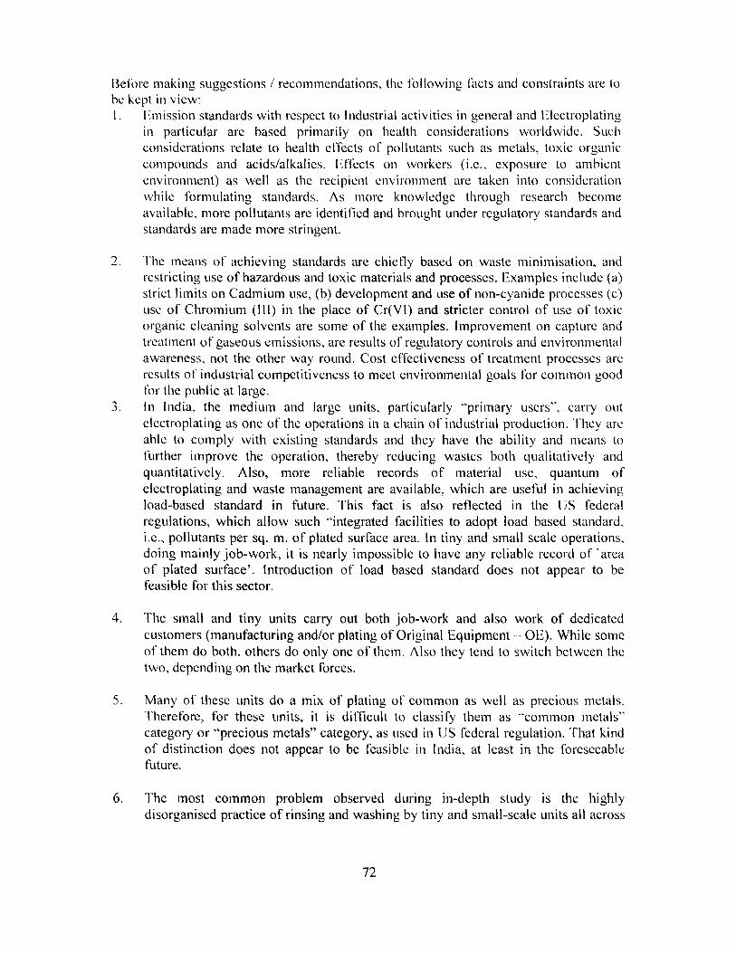
Before making suggestions / recommendations, the following facts and constraints are tohe kept in view:I. Emission standards with respect to Industrial activities in general and Electroplating
in particular are based primarily on health considerations worldwide. Suchconsiderations relate to health effects of pollutants such as metals, toxic organiccompounds and acids/alkalies. Effects on workers (i.e., exposure to ambientenvironment) as well as the recipient environment are taken into considerationwhile formulating standards. As more knowledge through research becomeavailable, more pollutants are identified and brought under regulatory standards andstandards are made more stringent.
2. The means of achieving standards are chiefly based on waste minimisation, andrestricting use of hazardous and toxic materials and processes. Examples include (a)strict limits on Cadmium use, (b) development and use of non-cyanide processes (c)use of Chromium (Ill) in the place of Cr(Vl) and stricter control of use of toxicorganic cleaning solvents are some of the examples. Improvement on capture andtreatment of gaseous emissions, are results of' regulatory controls and environmentalawareness, not the other way round. Cost effectiveness of treatment processes areresults of industrial competitiveness to meet environmental goals for common goodfor the public at large.
3. In India, the medium and large units, particularly "primary users", carry outelectroplating as one of the operations in a chain of industrial production. They areable to comply with existing standards and they have the ability and means tofurther improve the operation, thereby reducing wastes both qualitatively andquantitatively. Also, more reliable records of material use, quantum ofelectroplating and waste management are available, which arc useful in achievingload-based standard in future. This fact is also reflected in the US federalregulations, which allow such "integrated facilities to adopt load based standard,i.e., pollutants per sq. m. of plated surface area. In tiny and small scale operations,doing mainly job-work, it is nearly impossible to have any reliable record of 'areaof plated surface'. Introduction of load based standard does not appear to befeasible for this sector.
4. The small and tiny units carry out both job-work and also work of dedicatedcustomers (manufacturing and/or plating of Original Equipment - 0E). While someof them do both, others do only one of them. Also they tend to switch between thetwo, depending on the market forces.
5. Many of these units do a mix of plating of common as well as precious metals.Therefore, for these units, it is difficult to classify them as "common metals"category or "precious metals" category, as used in IJS federal regulation. That kindof distinction does not appear to be feasible in India, at least in the foreseeablefuture.
6. The most common problem observed during in-depth study is the highlydisorganised practice of rinsing and washing by tiny and small-scale units all across
72
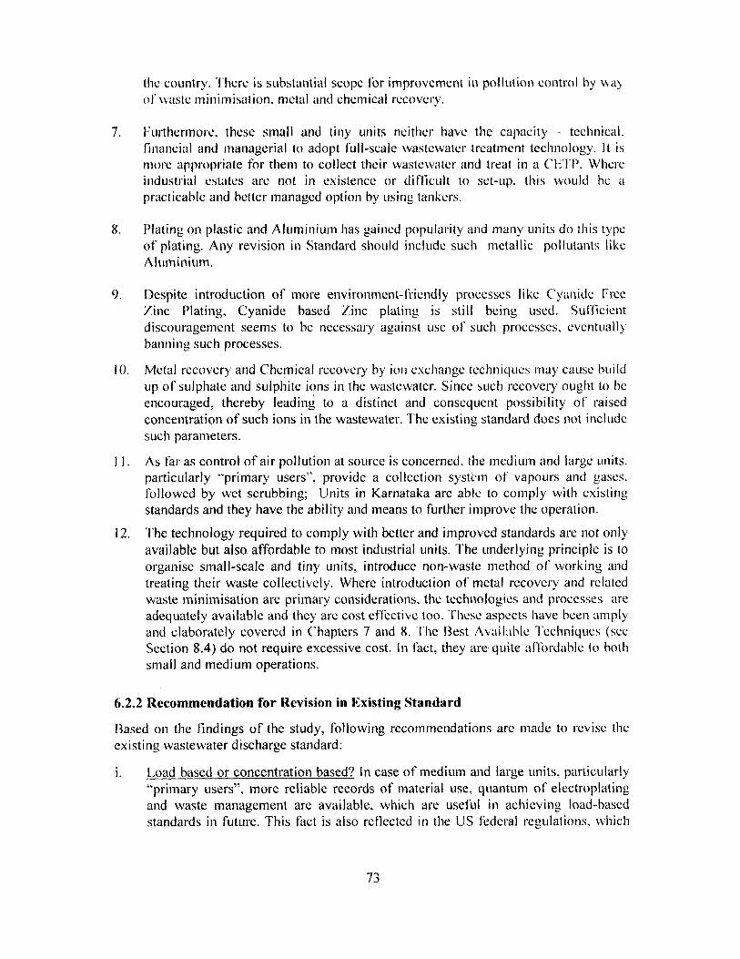
the country. There is substantial scope for improvement in pollution control by wayof waste minimisation, metal and chemical recovery.
7. Furthermore. these small and tiny units neither have the capacity - technical.financial and managerial to adopt full-scale wastewater treatment technology. It ismore appropriate for them to collect their wastewater and treat in a CET P. Whereindustrial estates are not in existence or difficult to set-up, this would he apracticable and better managed option by using tankers.
8. Plating on plastic and Aluminium has gained popularity and many units do this typeof plating. Any revision in Standard should include such metallic pollutants likeAluminium.
9. Despite introduction of more environment-friendly processes like Cyanide FreeZinc Plating, Cyanide based Zinc plating is still being used. Sufficientdiscouragement seems to be necessary against use of' such processes, eventuallybanning such processes.
10. Metal recovery and Chemical recovery by ion exchange techniques may cause buildup of sulphate and sulphite ions in the wastewater. Since such recovery ought to beencouraged, thereby leading to a distinct and consequent possibility of raisedconcentration of such ions in the wastewater. The existing standard does not includesuch parameters.
11. As far as control of air pollution at source is concerned, the medium and large units.particularly "primary users", provide a collection system of vapours and gases.followed by wet scrubbing; Units in Karnataka are able to comply with existingstandards and they have the ability and means to further improve the operation.
12. The technology required to comply with better and improved standards are not onlyavailable but also affordable to most industrial units. The underlying principle is toorganise small-scale and tiny units, introduce non-waste method of working andtreating their waste collectively. Where introduction of metal recovery and relatedwaste minimisation are primary considerations, the technologies and processes areadequately available and they are cost effèctive too. These aspects have heen amplyand elaborately covered in Chapters 7 and 8. The Best Available Techniques (seeSection 8.4) do not require excessive cost. In fact, they are quite affordable to bothsmall and medium operations.
6.2.2 Recommendation for Revision in Existing Standard
Based on the findings of the study, following recommendations arc made to revise theexisting wastewater discharge standard:
Load based or concentration based? In case of medium and large units, particularly"primary users", more reliable records of material use, quantum of electroplatingand waste management are available, which are useful in achieving load-basedstandards in future. This fact is also reflected in the US federal regulations, which
73
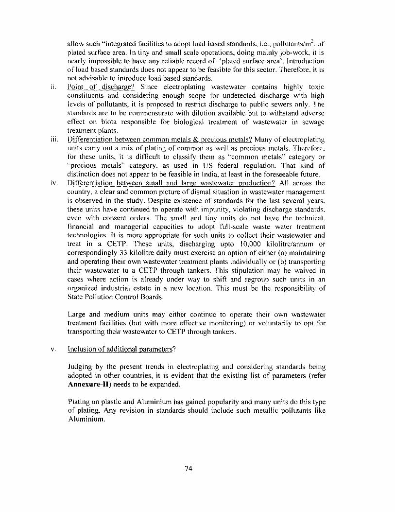
allow such "integrated facilities to adopt load based standards, i.e., pollutants/m 2 . ofplated surface area. In tiny and small scale operations, doing mainly job-work, it isnearly impossible to have any reliable record of `plated surface area'. Introductionof load based standards does not appear to be feasible for this sector. Therefore, it isnot advisable to introduce load based standards.
ii. Point of discharge? Since electroplating wastewater contains highly toxicconstituents and considering enough scope for undetected discharge with highlevels of pollutants, it is proposed to restrict discharge to public sewers only. Thestandards are to be commensurate with dilution available but to withstand adverseeffect on biota responsible for biological treatment" of wastewater in sewagetreatment plants.
iii. Differentiation between common metals & precious metals? Many of electroplatingunits carry out a mix of plating of common as well as precious metals. Therefore,for these units, it is difficult to classify them as ``common metals" category or"precious metals" category, as used in US federal regulation. That kind ofdistinction does not appear to be feasible in India, at least in the foreseeable future.
iv. Differentiation between small and large wastewater production? All across thecountry, a clear and common picture of dismal situation in wastewater managementis observed in the study. Despite existence of standards for the last several years,these units have continued to operate with impunity, violating discharge standards,even with consent orders. The small and tiny units do not have the technical,financial and managerial capacities to adopt full-scale waste water treatmenttechnologies. It is more appropriate for such units to collect their wastewater andtreat in a CETP. These units, discharging upto 10,000 kilolitre/annum orcorrespondingly 33 kilolitre daily must exercise an option of either (a) maintainingand operating their own wastewater treatment plants individually or (b) transportingtheir wastewater to a CETP through tankers. This stipulation may be waived incases where action is already under way to shift and regroup such units in anorganized industrial estate in a new location. This must be the responsibility ofState Pollution Control Boards.
Large and medium units may either continue to operate their own wastewatertreatment facilities (but with more effective monitoring) or voluntarily to opt fortransporting their wastewater to CETP through tankers.
v. Inclusion of additional parameters?
Judging by the present trends in electroplating and considering standards beingadopted in other countries, it is evident that the existing list of parameters (referAnnexure-II) needs to be expanded.
Plating on plastic and Aluminium has gained popularity and many units do this typeof plating. Any revision in standards should include such metallic pollutants likeAluminium.
74

Metal recovery and chemical recovery by ion exchange techniques may cause buildup of sulphate and sulphite ions in the wastewater. Since such recovery ought to beencouraged, thereby leading to a distinct and consequent possibility of raisedconcentration of such ions in the wastewater. The existing standard does not includesuch parameters.
The additional parameters along with their limit values are proposed in Table-6.1.
Table-6.1: Suggested List of Additional Parameters
Sl. No. Parameters Limit value (mg/1) T 10 be implemented in1 Aluminium 5.0Phase 12 Tin 2.0 Phase I3 Silver 1.2 Phase I4 Fluorides (as F) 15.0 Phase I5 Sul hides (as S) 2.0 Phase I6 Sulphates (as S)* 400.0 Phase 27 Trichloroethane 0.5 Phase 28 Trichloroethylene 0.5 Phase 2
-- ----- -- ----
9 Phosphates (as P) 5.0 Phase 2Note: * This parameter may be introduced in Phase-1, provided the local unitof the State Pollution Control Board feels that a higher value is likely todisrupt the operation of local sewage treatment plant and also cause sulphidecorrosion in sewers.** It is proposed that the revision be implemented in two phases.Implementation of Phase-I should commence on the date of notification ofstandards and for the implementation of Phase-2, a 2-year tinne period maybe allowed for the industry to organise themselves.
vi. Environmental friendly processes? Despite introduction of more environment-friendly processes like Cyanide Free Zinc Plating, Cyanide based Zinc plating isstill being used. Sufficient discouragement seems to be necessary against use ofsuch processes, eventually banning such processes.
vii. Air pollution? At present there is no regulatory standards for air borne pollutantsspecific to the electroplating industry.
At least, large and medium electroplating units are required to provide effectivecollection system of gases and vapours from all hot baths and treat the gasesand vapours with a water scrubber in Eirest phase. The scrubbed gases shouldconform to the standards as proposed in Table-6.2. Phased implementation issuggested, considering present state of the industry and facilities for reliabletesting and analyses.
75

"Fable-6.2: Proposed Standards for Air Emission from Electroplating Baths
i. No. Parameter El
2-- ---
Acid Mist (HC1 &H2SO4 ) Lead
--- ----—
-_.---- -
Nickel4 (_V I)5 Chromium (Othe rs)
nission Limitmg/Nm3
50
5555
To beimplemented in
Phase-I
Phase- IPhase-2Phase-2Phase-2- -------- -----------Phase-2
Note: Existing standards for SO2 and NO, shall continue to be applicable.
viii. Monitoring? Due to the very nature of the wastewater of electroplating industry, itis not practical to do the monitoring quite frequently, say, every week. This wouldbe rather expensive and less likely to be followed in practice. On the other hand, ifmonitoring is done at longer intervals, say once a month or once every two months,the real picture about compliance would not be available, leading to defeat of thevery purpose of monitoring. Flence a middle path seems to be reasonable, practicaland implementable.
It is therefore proposed that
• Some selected parameters (Cadmium, Chromium [Cr (VI) and Cr (Total)],Cyanides, Copper, Silver and Nickel) be monitored more frequently, while otherparameters be monitored at longer intervals.
• In case of tiny and small units, the selected parameters need to be monitored atleast once a week, generating 50 to 52 sets of values in a year. The otherparameters need to be monitored at least once a month, generating 12 sets ofvalues in a year. If 95% compliance is ensured, the performance may beconsidered satisfactory.
• In case of medium and large units, the selected parameters need to be monitoreddaily and the other parameters need to be monitored once a fortnight.
• Wherever it is possible, flow based grab sampling is to he done to getrepresentative sample.
• Source pollution for air emission (stack monitoring) should be carried outmonthly under normal operating conditions.
The proposed standards are given in Table 6.3
76

Table 6.3 Proposed Wastewater Discharge Standards for ElectroplatingIndustry
ÍÍ

Concentration not to exceed Co beSI. Parameters (mg/1, except pH & implementedNo ' temperature) in**
6.0 to 9.0I pH Same Existing
Temperature2 Shall not exceed 5 °c above the Same Existingambient temperature of the
receivin., body
Oil & Grease 10 Same Existing
4 Suspended Solids 100 Same Existing
5 Cyanides (as CN) 0.2 Same Existing
6 Ammoniaca l Nitrogen (as N) 50 Same Existing
Total Residual Chlorine (as Cl)7 1.0 Same Existing
8 J Cadmium (as Cd) 2.0 Same Existing
19 Nickel (as Ni) 3.0 Same Existing
10 Zinc (as 1_n)--- -- - - --
5.0 Same Existing
11 Hckavalr.nt Chromium (as Cr) j 0.1 Same Existing
12 total Chromium (as Cr) 2.0 Same Existing
i 3 Copper (as Cu)
1 ,ead (as Ph)
3.0
0.1
Same Existing
Same Existing14
15 , Iron (as Fe) 3.0 Same Existing
16 , Total Metal 10.0 Same Existing-------
Phase17 Aluminium 5.0
Phasei i: 2.0
Phase19 ^ílver 1.2
-/x
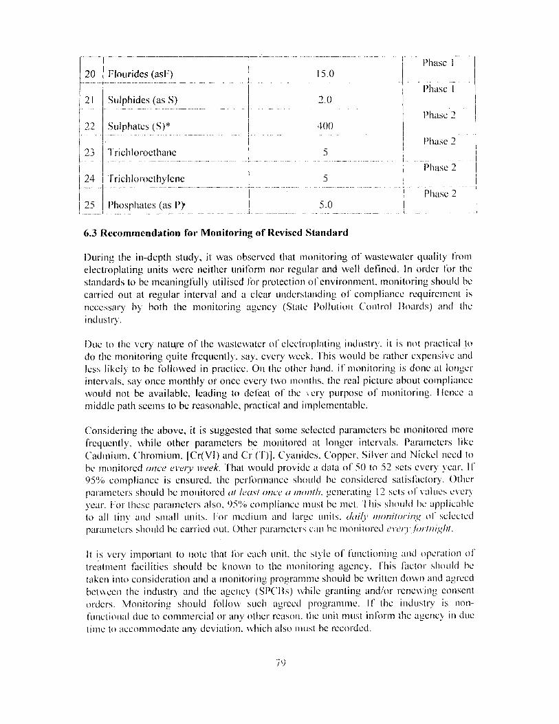
Phase 120 ( Flourides (asF)
15.0
Phase21
Sulphides (as S) 2.0
Phase 2Sulphates (S)* 400
Phase 2Trichloroethane
Trichloroethylene
Phosphates (as P}
6.3 Recommendation for Monitoring of Revised Standard
During the in-depth study, it was observed that monitoring of wastewater quality fromelectroplating units were neither uniform nor regular and well defined. In order for thestandards to be meaningfully utilised for protection of environment, monitoring should becarried out at regular interval and a clear understanding of compliance requirement isnecessary by both the monitoring agency (State Pollution Control Boards) and theindustry.
Due to the very natrwre of the wastewater of electroplating industry, it is not practical todo the monitoring quite frequently, say, every week. This would be rather expensive andless likely to be followed in practice. On the other hand. if monitoring is done at longerintervals, say once monthly or once every two months, the real picture about compliancewould not be available, leading to defeat of the %cry purpose of monitoring. I fence amiddle path seems to be reasonable, practical and implernentable.
Considering the above, it is suggested that some selected parameters be monitored morefrequently. while other parameters be monitored at longer intervals. Parameters likeCadmium. Chromium. [Cr(VI) and Cr ("f)). Cyanides, Copper, Silver and Nickel need tobe monitored once every week. That would provide a data ot' S0 to 52 sets every year. If95% compliance is ensured, the performance should he considered satisihctory. Otherparameters should be monitored ai least once a 11 owh. generating 12 sets of values everyyear. lor these parameters also. 90 compliance must be niet. This should be applicableto all tins and small units. For medium and large units. c%/ili' ntoniloring of selectedparameters should be carried out. Other parameters can he monitored evei lorini^hi.
It is very important to note that for each unit. the style of functioning and operation oftreatment facilities should be known to the monitoring agency. This ir,ctor should betaken into consideration and a monitoring, programme should he written down and agreedbetween the industry and the agency (SPCI3s) while granting and/or renewing consentorders. Monitoring should follow such agreed programme. If the industry is non-functional due to commercial or any other reason. the unit must inform the agency in duetime to accommodate any deviation. which also must be recorded.
7 9
Source Pollution for air emission (stack monitoring) should be carried out monthly undernormal operating conditions.
6.4 Safe keeping of Data
Keeping data and records safely and in a manner that data can be retrieved at ease is ofgreat importance. Such data form a reliable base over which to build and modify fromtime to tinne regulatory or other suitable mechanism for - pollution control andenvironment protection measures. It is recommended that data should be kept incomputerised data-base for aperiod of at least 5 years. Data ledgers co-signed byindustrial unit and monitoring, agency should he kept, similar to audited accounts record.
(S t)