warning! do not use a 12v test light to locate or test any ... · pdf filex some good...
TRANSCRIPT

2
1. MOUNT THE CONTROL UNIT:
Install the control unit securely in a safe, dry place inside the vehicle. Never install the control unit under the hood. The control unit should be mounted in a suitable location that would be difficult for a potential thief to located, but allow for convenient installation position. Do not mount the control unit in the way of any moving parts Do not mount the control unit near any heat sources. Mount the control unit in a way that it does not vibrate or rattle. Avoid installing the unit anywhere easily visible under the driver's side dash. The first place a thief will go when attempting to steal a car is the driver's side under dash to access the starter and ignition wires. If the control unit is easily visible, it can be disconnected and defeated during a theft attempt. Some good locations are above or behind the glove box, under the center console, above the under dash fuse box, or in the dash behind the radio. For maximum remote range, mount the control unit high under the dash and as far away as possible from metal.
2. ROUTE THE ANTENNA:
The position and location of the antenna will affect remote control range. Do not shorten or lengthen the antennaRoute the antenna wire away from the control unit Avoid running the antenna along any wire harnesses Keep the antenna and control unit as far away from metal as possible
3. ROUTE WIRES FROM THE CONTROL UNIT:
Wires should be carefully run from the control unit to each component. Wires should be wrapped in electrical tape, split loom, or plastic tubing to match the look of the factory wires. Wires should be run alongside factory wires to make the wires look as if they came that way from the factory. In most vehicles you will need to route your wiring to the ignition harness, the driver’s kick panel, under the hood, and sometimes the trunk or passenger kick panel. Plan out what wires need to be routed to each location and carefully route your wires to that location and make your connections in that location before moving on.
4. INSTALL THE SIREN:
Running the siren wire from the alarm brain inside the car to the siren under the hood should be carefully considered. Unlike an amplifier power wire, the siren wire is relatively small gauge, which makes using an existing hole through the firewall a good option. An alternate method, if an existing hole cannot be found, is to drill a hole in the firewall. Be certain not to drill through any fluid lines or factory cables. Use a plastic grommet to protect the wires from being cut by the metal edge of the drilled holes. The siren must be mounted securely under the hood. Mount the siren where the siren cannot be seen or reached from below the vehicle. Mount it away from any heat sources or moving parts Point the siren down to avoid water collecting in it. Protect and conceal wiring by wrapping it with split loom or vinyl tubing and routing it alongside factory wiring.
? Having Trouble Running Your Wires Through The Firewall?
Most vehicles have rubber grommets that are large enough to feed your siren wire through using a coat hanger. If the vehicle has an automatic transmission, there is usually a spot reserved for where the clutch cable would go through the firewall. This is usually an excellent spot to drill a hole. Avoid drilling a hole whenever possible. Some vehicles have wires, fuel lines, or brake lines that run inside the firewall, invisible from either side.
WARNING! Do not use a 12V test light to locate or test any wires! A test light may cause serious damage to vehicle electronics. Only use a digital multi-meter to test circuits.
The picture above shows that a hole was drilled in the spot where the clutch cable would gothrough the firewall. The hole was drilled using a unibit.
A unibit is the preferred method of drilling throughmetal.
Whenever drilling holes, always use a plastic or rubbergrommet to protect your wiring and prevent any sharpedges from damaging the wire’s insulation and causingany possible shorts.

3
5. MOUNT THE LED STATUS INDICATOR:
Most alarm and remote start systems have an LED status indicator used for system programming and diagnostics. It also serves as a theft deterrent. The LED should be installed in a place visible from both sides and the rear of the vehicle. It is best to install the LED on a small removable panel like a blank switch or dash bezel. Check for clearance on both sides before any drilling. Use quick-disconnects near the LED if the panel is removable. This allows the panel to be removed without having to cut wires
6. MOUNT THE OVERRIDE/ PROGRAM SWITCH:
Alarm and remote start systems have an override switch to disable the alarm system if the remotes are damaged or missing. The switch is also used for feature programming. Care must be given to mounting the override switch since just by hotwiring the ignition and flicking the switch, a thief can disarm the alarm and steal the car. The alarm override switch should be mounted in someplace hidden but convenient. Good locations include behind the hood release lever, inside the ashtray opening, inside the center console (where it can't be accidentally bumped), or in the glove box. Before drilling, check for clearance on both sides.
7. SECURE THE SHOCK SENSOR (Alarm Installations Only):
Shock or impact sensors are the most common sensors included with vehicle security systems. They are designed to detect various degrees of impact to the vehicle during a break-in attempt. Some shock sensors have a dual-stage response. A light shock to the vehicle may only chirp the siren and/or flash the parking lights to warn away a potential thief or intruder. A heavy shock will trigger the alarm. These sensors are most effective in detecting a punched-out door lock. However, when adjusted to be sensitive enough to detect breaking glass, they will false alarm. The shock sensor should be securely mounted underneath the dash. Use double sided tape or a wire tie to secure it to an air duct, wire harness, or trim panel. Avoid mounting it in the way of any moving parts or relays. Avoid mounting it to the steering column or screwing it to metal, as it will cause poor sensitivity
8. SECURE THE RADAR, MICROWAVE, and FIELD DISTURBANCE SENSORS (Alarm Installations Only):
These sensors are very useful in helping protect vehicle contents. They flood the area to be protected with a microwave energy field. When the field is disturbed by a large mass such as a human body, the sensor sends a trigger to the alarm control unit to trigger the alarm. The larger the object the faster the sensor will react. These sensors are ideal for protecting convertibles and vehicles with removable tops.
Like most shock sensors, these sensors can also be dual stage sensors. This means they can warn at a distance and trigger to a full alarm if the interior space is entered.
Radar, microwave, and field disturbance sensors generally cover an area similar to the head of a mushroom. It should be mounted in the center of the interior of the vehicle, facing upward.
If your vehicle has a center console between the front seats, mounting the sensor under this console facing up may be an ideal location. Make sure that the sensor is not placed behind any metal parts or major harnesses of the car. The sensor will detect through fabric or plastic, and it needs to face towards the area that is to be protected.
The sensor should always be adjusted outside, away from any fluorescent lights. These lights, as well as temperature, and weather conditions can affect the sensitivity of these sensors.
9. LOCATE AND CONNECT TO TACHOMETER WIRE (Remote Start Installations Only):
Remote starts have a tachometer wire input to monitor the tachometer signal when the vehicle is remote started A multi-meter capable of testing AC voltage is needed to test for the tachometer wire. The tachometer wire will meter between 1V and 6V AC. Common locations for the tachometer are the ignition coil, instrument cluster, engine computers, or test connector.
WARNING! Do not test tachometer wires with a test light or logic probe. The vehicle WILL BE DAMAGED.
To find a tachometer wire with a multi-meter: 1. Set meter to AC voltage. 2. Attach the (-) probe of the meter to chassis ground. 3. Start and run the vehicle 4. Probe the wire suspected of being the tachometer wire with
the other probe. 5. If this is the correct wire, the meter will read between 1V and
6V.
Tach location near battery for 98-02 Honda Accord 4-cylinder
? Having trouble finding a tachometer wire?
Many vehicles have a tachometer wire available behind theinstrument cluster. A fuel injector wire can also be used for a tachometer signal onmost vehicles. Each injector will have two wires. Use the wirethat is not common. For example, at one injector the wires maybe BLACK/WHITE and RED. At the next injector the wires maybe GREEN/WHITE and RED. At the next injector the wires maybe BLUE/RED and RED. At the next injector wires may bePURPLE/WHITE and RED. In this case you would use any wirethat is not RED.

4
10. LOCATE THE HOOD TRIGGER WIRE OR INSTALL A HOOD PIN:
Some remote start systems have a hood trigger input to shut down or disable the remote start when the hood is opened. This is a safety feature. For a security system, the hood trigger input will trigger the alarm if the hood is opened. The intent of a hood trigger input is to protect the engine compartment and the contents that are susceptible to tampering such as the siren, battery, or starter. Generally, models equipped with a factory security system have a factory hood pin switch. This wire can often be found at the factory anti-theft unit or at the hood pin switch.
Some vehicles do not have a factory hood pin. In order to protect the engine compartment a hood pin must be added. Some systems include a pin switch and pin switch bracket that can be used as a hood pin, or they are available at most car audio and electronics stores.
The pin switch bracket is used to mount the hood pin switch. The bracket is typically and “L” shape and is mounted to the side of the firewall or inside fender area.
To find the hood pin trigger wire with your multi-meter: 1. Set to DC voltage 2. Attach the (+) probe to 12V constant 3. Probe the wire you suspect of being the hood trigger wire with the (-) lead 4. The meter should indicate 12V with the hood open if you have found the correct wire 5. The meter will then read 0V when the hood is closed.
To install a hood pin switch: 1. Find a suitable mounting location for the pin switch mounting bracket on the framing around the hood inside the engine bay. The mounting location of
the hood pin switch is vital to its performance and the level of protection it provides. The hood pin switch should be mounted as far to the front of theengine bay as possible to ensure instant triggering when the hood is opened.
2. Test for appropriate location. Measure the area below where the pin switch will be installed to ensure the pin switch can extend without hitting anythingbelow it. Locate the pin switch in an area in which it will not be prone to being bent or broken such as by someone performing regular maintenance.
3. Use screws provided with the alarm/remote start system and mount the pin switch bracket. 4. Mount the pin switch with the provided hardware. Attach the hood trigger wire. 5. Arm the alarm and test the pin switch. Adjust height if necessary.
NOTE: Most alarms have a separate input for a hood trigger. If not, the hood trigger can be hooked up to the door trigger input. Diode isolate as shown below.
A few examples of hood pins added for an alarm/remote start installtion:

5
11. CONNECT CHASSIS GROUND:
This is one of the most important connections. A poor or improper ground causes 90% of all problems that may arise with an alarm or remote start. The best ground point in a vehicle is a place with a good physical connection to the same metal that the vehicle battery ground itself shares.Avoid using the bracing underneath the dash. This is a high-resistance ground point and should not be used. It is preferred that a factory ground point (usually located in the driver’s kick panel) is used. Some manufacturers in their installation manual recommend and insist on using the negative terminal of the battery for the alarm or remote start system’s ground point. Connect this wire to bare metal, preferably with a factory bolt rather than your own screw. Screws tend to either strip or loosen with time. Ground all components to the same point. If a screw must be used, connect chassis ground to bare metal and use a star washer to ensure a proper ground connection. Check for clearance on both sides before drilling
12. LOCATE AND CONNECT TO 12V CONSTANT POWER:
The alarm and remote start system has a 12V constant power input. This powers the alarm or remote start system. There are two possible sources from which to supply the system with constant power. The (+) terminal of the battery can be used. This is one of the best locations for constant power. Also, some new vehicles use low current wires at the ignition switch that should not be used to supply power for additional electrical components, such as an aftermarket alarm or remote start system. In these cases it is recommended to run a 10-gauge wire from the battery to supply power to the alarm, remote start, and any other components such as relays, window control modules, etc.
The constant 12V supply of the ignition switch may be used to supply power to the system. The 12V constant wire at the ignition switch is usually the thickest wire in the ignition harness. Many installers prefer connecting the system’s 12V constant input for the reason that it is a convenient location and it’s connection is not readily visible or easily defeated. It is recommended that if additional accessories are installed such as power window control modules, the 12v constant power connection be made at the battery. Always fuse within 12 inches of this connection whether it is made at the battery or the ignition harness.
NOTE: If the battery is used to supply power, the terminal should NOT be disconnected. On most newer vehicles, the stereo requires thata code be entered after the battery is reconnected. Without the correct code, the stereo will not function and a trip to the dealership will berequired. Also, on some vehicles, disconnecting the battery may trigger a “check engine” light or similar error code. Make connections byremoving lug nut from cable clamp without detaching clamp.
The picture above displays the ignition harness of a 1998 Chevy Tahoe. In this harness, the 12V Constant, Starter, Accessory, and Ignition wires can befound. They are usually very easily distinguishable as the thicker wires in this harness. You can also find the Passlock II wires. (Interfacing with the PasslockII system is explained later in this document.
Take care in working with the ignition harness of any vehicle. Many other wires, including airbag wires, can usually be found in the ignition harness of mostvehicles. You want to be careful not to accidentally unplug or damage any of the connectors or the wiring. Unplugging any of the connectors may deploy theairbags or trigger a “check engine” light or similar error code light to appear on the dash.
The ignition harness of other vehicles will be similar.

6
13. LOCATE AND CONNECT TO THE 12V IGNITION WIRE:
Connect the alarm system’s ignition input wire to a main ignition wire. If installing a remote start system, connect the remote start system’s ignition output to the vehicle’s main ignition wire. The ignition wire is often found in the harness coming from the key cylinder. This wire is powered when the key is in the run or start position. This wire powers the ignition system and the fuel delivery system.
Most vehicles have more than one ignition wire that must be energized for the remote start process in order for the vehicle to run properly. If the system only has one (+) ignition output, use a relay for each additional ignition wire that must be energized.
PIN CONNECTION
85 (+) OUTPUT FROM REMOTE START MODULE TO 1ST
IGNITION WIRE
86 (-) OUTPUT WHEN REMOTE START IS ACTIVATED
87 12V CONSTANT FUSED (25 AMP CAPABLE)
87A NO CONNECTION
30 TO (+) SECOND IGNITION WIRE
To find the 12V ignition with a multi-meter: 1. Set meter to DC voltage 2. Attach the (-) probe of the meter to chassis ground 3. Probe the wire you suspect of being the ignition wire with the (+) probe. The steering column harness or ignition harness is an excellent place to find
this wire. 4. Turn the ignition key to the run position. If your meter reads 12V go to the next step 5. Turn the key to the start position. The meter should remain steady. If it drops close to or all the way to zero, that is not the correct wire. Go back to step
3. If it stays steady at 12V that is the ignition wire.
NEVER connect two Ignition wires of the vehicle together to avoid using a relay. If the vehicle manufacturer wanted the Ignition 1 and 2wires to be summed, they would have done it at the factory! This is not only unwise because of the current draw issues, but this is aperfect opportunity for the dealer to call the warranty void if ANYTHING relating to the electrical system goes wrong.

7
To find 12V accessory with a multi-meter: 1. Set meter to DC voltage 2. Attach the (-) probe of the meter to chassis ground 3. Probe the wire you suspect of being the accessory wire with the (+) probe. The steering column harness or ignition harness is an excellent place to find
this wire. 4. Turn the ignition key to the accessory and then the run position. If your meter reads 12V on each, go to the next step 5. Turn the key to the start position. The meter should drop to zero. If it does, this is the correct wire.
LOCATE AND CONNECT TO THE 12V IGNITION WIRE, cont.
PIN CONNECTION
85 (-) OUTPUT WHEN REMOTE START IS ACTIVATED
86 (+) OUTPUT TO IGNITION WIRE
87 12V CONSTANT FUSED 25 AMP CAPABLE
87A CONNECT TO IGNITION WIRE ON KEY CYLINDER SIDE
30 CONNECT TO IGNITION WIRE ON CAR SIDE
14. LOCATE AND CONNECT TO THE 12V ACCESSORY WIRE (Remote Start Installations Only) :
This wire powers the vehicle's climate control system. This wire will need to be located only when installing a remote start system. This wire is powered when the key is in the accessory and run position. This wire will not show 12V during the cranking cycle. Most often found in the harness coming from the key cylinder.
Many vehicles have more than one accessory wire that must be energized for the remote start process in order for the vehicle to run properly. If the system only has one (+) accessory output, use a relay for each additional accessory wire that must be energized and wire as shown:
NEVER connect two Accessory wires of the vehicle together to avoid using a relay. If the vehicle manufacturer wanted the Accessory 1and 2 wires to be summed, they would have done it at the factory! This is not only unwise because of the current draw issues, but this is a perfect opportunity for the dealer to call the warranty void if ANYTHING relating to the electrical system goes wrong.
NOTE: On 2000-Up Toyota Celicas and Echoes, When doing remote start system, the 12V Ignition wire must be isolated from the ignitionswitch using a relay to prevent backfeeding into the ignition switch. Use a relay and follow the diagram below. This will only need to be donewhen installing a remote start system.

8
Use a relay as shown below:
LOCATE AND CONNECT TO THE 12V ACCESSORY WIRE, cont.
PIN CONNECTION
85 (+) OUTPUT FROM REMOTE START MODULE TO 1ST
ACCESSORY WIRE
86 (-) OUTPUT WHEN REMOTE STARTED
87 12V CONSTANT FUSED 25 AMP CAPABLE
87A NO CONNECTION
30 TO (+) SECOND ACCESSORY WIRE
PIN CONNECTION
85 (-) OUTPUT WHEN REMOTE STARTED
86 (+) OUTPUT FROM REMOTE START TO 1ST
ACCESSORY WIRE
87 12V CONSTANT FUSED 25 AMP CAPABLE
87A TO KEY CYLINDER SIDE OF ACCESSORY WIRE
30 TO CAR SIDE OF ACCESSORY WIRE
NOTE: On 1993-1997 Nissan Altimas, when installing a remote start system a relay must be used to isolate the accessory wire from the ignition key switch.

9
15. LOCATE AND CONNECT TO THE STARTER WIRE:
The starter wire provides 12V directly to the starter or a relay controlling the starter. The starter wire is often found in the harness coming from the key cylinder.
Some vehicles (Nissans, Infinitis, as well as some European vehicles) have more than one starter wire. This second starter wire is a “cold start” wire. This second starter wire is needed for remote start installations only. This second starter wire must be energized for the remote start process in order for the vehicle to start properly. If the system only has one (+) starter output, use a relay for each additional starter wire that must be energized and wire as shown:
PIN CONNECTION
85 (+) OUTPUT TO 1ST
STARTER WIRE
86 (-) OUTPUT FROM REMOTE START WHEN REMOTE START IS ACTIVATED
87 12V CONSTANT FUSED 25 AMP CAPABLE
87A NO CONNECTION
30 TO (+) SECOND STARTER WIRE
PIN CONNECTION
85 (+) OUTPUT FROM REMOTE START SYSTEM TO ACCESSORY WIRE
86 (-) OUTPUT WHEN REMOTE STARTED
87 CHASSIS GROUND
87A NO CONNECTION
30 TO SECOND STARTER WIRE THROUGH A 180-OHM RESISTOR
To find the starter wire with your multi-meter: 1. Set your meter to DC voltage 2. Attach the (-) probe to chassis ground. 3. Probe the wire you suspect of being the starter wire with the (+) probe. 4. Turn the key to the start position. If the meter reads 12V go to the next step 5. Cut the wire you suspect of being the starter wire 6. Attempt to start the car. If the starter engages, reconnect it and go back to step 3. If the starter does not engage, that is the correct wire
NOTE: 2004 Chrysler Pacifica and 2001-Up Dodge Caravan, Chrysler Voyager, and Chrysler Town & Country models have a second starter wire (example shown below left) that must be energized when remote starting the vehicle. There is a PURPLE/BROWN wire at the ignition harness that must be activated with a resisted ground during crank, otherwise the engine will crank but not start most of the time. Use a relay and connect as shown below.

10
16. STARTER KILL RELAY:
Most security systems include a starter disable. The security system controls a relay that interrupts the flow of power to the starter solenoid when the alarm is armed and an attempt is made to start the vehicle. However, it is important to note that if the vehicle has a manual transmission, this will not prevent the vehicle from being “roll started.” The starter kill relay should not be easily visible upon removing the under dash panel Solid wire connections must be made. For maximum dependability, solder and shrink tube the connections. Wires should be wrapped in 3M electrical tape or plastic tubing to match the factory wiring.
PIN CONNECTION
85 12V CONSTANT FUSED
86 (-) GROUND WHEN ARMED OUTPUT
87 NO CONNECTION
87A STARTER WIRE- IGNITION SWITCH SIDE
30 STARTER WIRE- STARTER SIDE
17. LOCATE AND CONNECT TO THE BRAKE WIRE (Remote Start Installations Only):
Remote start systems have a brake wire input to monitor the brake light to prevent an unauthorized driver from driving the vehicle and to switch to normal engine operating condition. The remote start will shut down or fail to start any time the brake pedal is depressed. The remote start's brake switch input MUST be connected and the brake light must be in working condition.
To find the (+) brake wire with your multi-meter: 1. Set to DC voltage 2. Attach the (-) probe to chassis ground 3. Probe the wire you suspect of being the brake wire with the other probe. 4. Depress the brake pedal. The meter should read 12V with the pedal depressed and 0V with the pedal at rest.
If the system does not come pre-wired for a starter disable, use a relay and wise as shown:
Location of the brake wire at the driver’s fusebox of a 1998 Honda Accord EX.
Location of the brake wire at the brake pedal switch of a 1998 Honda Accord EX.
Having trouble finding the brake wire?
On some vehicles, reaching the brake switch may be difficult or near impossible to reach.
The brake switch wire can usually also be found in the driver’s kick panel in a harness running towards the rear of the vehicle.
On some vehicles, the brake wire can be found in a harness at the fuse box.

11
LOCATE AND CONNECT TO THE BRAKE WIRE, cont.
18. LOCATE AND CONNECT THE HORN HONK TRIGGER WIRE (Optional):
Most alarm and remote start systems have a horn honk output or a siren output that can be programmed as a horn honk output. In some installations it may be desired that the system honk the horn when the doors are locked and unlocked or as a panic feature. The horn trigger wire is usually found in one of the bundles of wires at the steering column.
PIN CONNECTION
85 (-) HORN TRIGGER OUTPUT
86 12V CONSTANT FUSED
87 CHASSIS GROUND
87A NOT CONNECTED
30 (-) HORN TRIGGER WIRE
To find the (-) horn honk trigger wire with your multi-meter: 1. Set to DC voltage 2. Attach the (-) probe to chassis ground 3. Probe the wire you suspect of being the horn honk trigger wire with the other probe. The meter should read 12V. 4. Honk the horn. The meter should drop to 0V when the horn is honked. If it does, that is the correct wire.
NOTE: Always take care when working around the airbag wires. Do not probe or cut into them.
NOTE: Use a relay and wire as shown:
Location of the brake wire in the driver’s kick panel of a 1999 Toyota Avalon.
Location of the brake wire at the driver’s kickpanel of a 1996 Chevy Cavalier.
Location of the brake wire at the driver’s kickpanel of a 2001 Toyota 4Runner

12
LOCATE AND CONNECT THE HORN HONK TRIGGER WIRE , cont.
In some vehicles, there is little space under the hood to mount a siren. Or some people may prefer that the aftermarket system honk the horn instead of using a siren. Most aftermarket systems have a positive (+) siren output. The system may need to be programmed to honk the horn. Check your system’s instructions.
PIN CONNECTION
85 (+) SIREN OUTPUT
86 CHASSIS GROUND
87 CHASSIS GROUND
87A NOT CONNECTED
30 (-) HORN TRIGGER WIRE
NOTE: Use a relay and wire as shown:
The location of the horn trigger wire in the ignition harness of a 1999 Honda Accord.
The location of the horn trigger wire at the fusebox of a 2001 Toyota 4Runner.
The location of the horn trigger wire in the
driver’s kickpanel of a 1999 Toyota Avalon.
13
LOCATE AND CONNECT THE HORN HONK TRIGGER WIRE , cont.
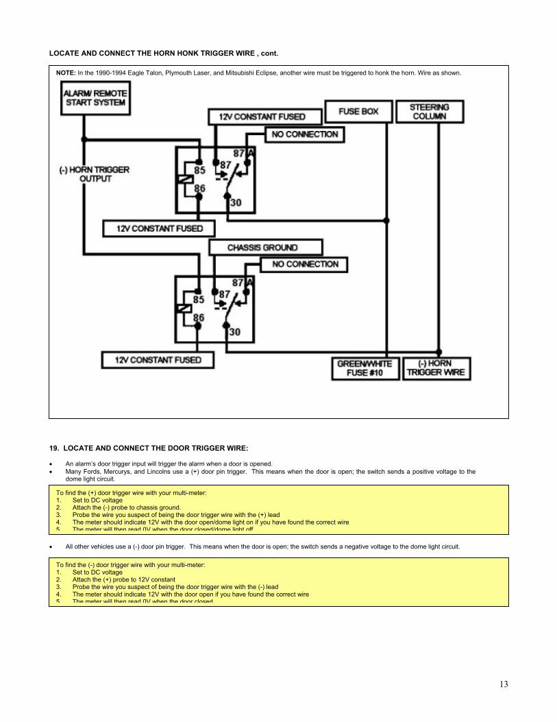
19. LOCATE AND CONNECT THE DOOR TRIGGER WIRE:
An alarm’s door trigger input will trigger the alarm when a door is opened. Many Fords, Mercurys, and Lincolns use a (+) door pin trigger. This means when the door is open; the switch sends a positive voltage to the dome light circuit.
All other vehicles use a (-) door pin trigger. This means when the door is open; the switch sends a negative voltage to the dome light circuit.
To find the (-) door trigger wire with your multi-meter: 1. Set to DC voltage 2. Attach the (+) probe to 12V constant 3. Probe the wire you suspect of being the door trigger wire with the (-) lead 4. The meter should indicate 12V with the door open if you have found the correct wire 5 The meter will then read 0V when the door closed
NOTE: In the 1990-1994 Eagle Talon, Plymouth Laser, and Mitsubishi Eclipse, another wire must be triggered to honk the horn. Wire as shown.
To find the (+) door trigger wire with your multi-meter: 1. Set to DC voltage 2. Attach the (-) probe to chassis ground. 3. Probe the wire you suspect of being the door trigger wire with the (+) lead 4. The meter should indicate 12V with the door open/dome light on if you have found the correct wire 5 The meter will then read 0V when the door closed/dome light off

14
LOCATE AND CONNECT THE DOOR TRIGGER WIRE, cont.
Pictured is the location of the door trigger wire in the driver’s kick panel of a 1999 Toyota Avalon.
Pictured is the location of the door trigger wirebehind the fuse box of a 2001 Toyota4Runner.
Pictured is the location of the door trigger wireat the passenger fuse box of a 1999 HondaAccord.
On most vehicles the door trigger wire can be found in a harness in the driver’s kick panel or passenger kick panel or at the fuse box.
On many General Motors, Ford, Dodge, and Chrysler vehicles, thedoor trigger wire can be found behind the headlight switch or dimmerswitch. This pictureshows the location of the door trigger wire in theconnector on the back of the headlight switch in a 1998 GMC Yukon.This location will be similar in 1998-2000 GM Full Size Pickups andSUVS. (Suburban, Tahoe, Yukon, Escalade)
The pictures below show the locations of the driver door trigger wire and the passenger door(s) trigger wires in the driver’s kick panel of a 1997 Pontiac Sunfire. This location will be similar in 1995-Up Pontiac Sunfires and Chevy Cavaliers.

15
For vehicles with a door trigger wire for the driver’s door, the front passenger door, the left rear door, and the right rear door, wire as shown:
LOCATE AND CONNECT THE DOOR TRIGGER WIRE, cont.
For vehicles with a door trigger wire for the driver’s door and the passenger door(s) wire as shown:
For vehicles with a door trigger wire for the driver’s door and the passenger door and the rear doors, wire as shown:
NOTE: On many newer vehicles, the dome light has a delay, meaning that the dome light stays on for 30-60 seconds after the last door is closed. This can poseproblems on some alarm installations. Most aftermarket alarms will give an error chirp after arming because of the delayed dome light. To avoid the dome lightdelay, individual door trigger wires must be found. Locate the door trigger wire for each door and then diode isolate, following the appropriate diagram.
Individual door trigger wires for a 2001 Dodge Caravan are shown. Notice there is a separate door trigger for each of the front doors, the two sliding doors,and the rear hatch.

16
In some vehicles (generally, newer American vehicles such as Ford, Dodge, and Chrysler vehicles) the vehicle “powers down” various computers in the vehicle to conserve power. This will cause the alarm to false as it senses a drop in voltage and mistakes it for a door being opened. To prevent this, a relay must be used.
LOCATE AND CONNECT THE DOOR TRIGGER WIRE, cont.
NOTE: When doing security on 95-97 Chevy Blazers, Oldsmobile Bravadas and GMC Jimmys, the door trigger wire catches all doors, but there is a dome light delay. To keep the alarm from reading the delay, place a diode in-line on the white door trigger wire with the anode towards the keyless module. Attach your door trigger wire to the cathode side of the diode. On non-keyless models there is a module with 5 wires located where the keyless normally resides. The white wire there catches only the front two doors. To catch the rear doors use the white wire at the driver’s side rear pin switch.
1. Go to each rear door pin switch wire. The wire color is WHITE. 2. Cut the factory wire and add a 6AMP diode in-line with the cathode facing towards the pin switch. This must be done with both rear doors. 3. Attach a wire to the cathode side of each 6-amp diode. 4. Tap each front door latch switch. 5. Diode isolate each front door trigger with the wire from the rear doors together and connect them to the door trigger input of the alarm.
NOTE: 4-door 1991-1994 Chevy Cavalier and Pontiac Sunbirds use a unique door trigger setup. The front doors use a latch switch and the rear doors use standard pin switches. To interface an aftermarket alarm with this system, you must use the following steps. This setup only applies to 4-door models with rear pin switches.

17
LOCATE AND CONNECT THE DOOR TRIGGER WIRE, cont.
99-Up Ford Windstar Door Trigger
If there is a courtesy light under the driver dash, use the diagram below to interface the door trigger to an alarm system. Tap a wire off of the ORANGE/WHITE wire at the light and connect it to pin 85 of the relay. Tap a wire off of the PURPLE/WHITE wire at the light and connect it to pin 86 of the relay. Pin 87 should be connected to chassis ground. Connect the (-) door trigger input of the alarm to pin 30 of the relay. A relay must be used to avoid any false alarm problems doe to module shutdown.
Without Courtesy Light Under Dash
On some trim levels, it is not possible to make a direct connection of the door trigger wire to the domelight. If the vehicle does not have a courtesy light under the dash, door trigger wires for each of the doors much be located and connected to the alarm. The door trigger wires for the front two doors and the hood trigger wire are located at the Front Electronic Module under the driver’s dash against the firewall. The Rear Electronic Module is located in the passenger rear quarter panel. Find all wires and follow the diagram on the following page as shown. Diodes must be used to block the change of polarity in the modules and to prevent the door triggers from being detected by each other.
WIRE WIRE COLOR
HOOD TRIGGER WIRE PURPLE/ORANGE
LEFT FRONT DOOR TRIGGER WIRE LT.GREEN/BLACK
RIGHT FRONT DOOR TRIGGER WIRE YELLOW/LT.GREEN
LEFT REAR DOOR TRIGGER WIRE WHITE/PURPLE
RIGHT REAR DOOR TRIGGER WIRE DK.BLUE/LT.GREEN
NOTE: The rear hatch wires are normally closed. To interface, a Closed Loop Adapter (part # 502T) must be used or a pin switch must be added.

18
LOCATE AND CONNECT THE DOOR TRIGGER WIRE, cont.
Most alarm and remote start systems include the option of dome light supervision. Dome light supervision will turn on the vehicle’s dome light for a set time when the system unlocks/disarms the vehicle. This allows the user to check the interior of the vehicle for an intruder before entering.
For dome light supervision on a vehicle with a negative door trigger wire, connect the dome light supervision output as shown below:
For dome light supervision on a vehicle with a positive door trigger wire, connect the dome light supervision output as shown below:
NOTE: When adding dome light supervision on 93-97 Toyota Corollas and Geo Prizms, use the door trigger wire and relay isolate the door trigger wire to keep ground from entering the fuse box side of the wire or unlock will not function properly. Use a relay as shown:
Pictured below is the location of the domelight supervision wire at the under-dash light of a 1998 Chevy Suburban.

19
20. LOCATE AND CONNECT THE TRUNK TRIGGER WIRE:
Most vehicles have a separate wire that turns on a dome light when the trunk, rear hatch, or rear doors are opened. If this is the case, most alarms have a separate input for a hood pin or trunk pin that can be hooked to the trunk trigger wire to set off the alarm if the trunk is opened.
The trunk trigger wire can be found in most vehicles in a harness running to the rear of the vehicle in the driver’s kick panel or the passenger kick panel
In some older vehicles, the trunk trigger wire may only be found at the light in the trunk of the vehicle. If the vehicle is not equipped with a light in the trunk, it will be necessary to add a trunk pin or mercury switch.
21. LOCATE AND CONNECT THE PARKING LIGHT WIRE:
Alarm and remote start systems have a parking light output. This is used to flash the parking lights when the vehicle is armed or disarmed, the doors are locked and unlocked with the remote, when the alarm is triggered, or when the remote start is activated. On some systems the parking light output is used for system diagnostics. Connecting the parking light output is not always necessary, but recommended. Most vehicles use a (+) parking light circuit. Most aftermarket systems have a built-in relay for the parking light output. This allows the parking light output to be connected directly to the parking light wire.
To find the trunk pin trigger wire with your multi-meter: 1. Set to DC voltage 2. Attach the (+) probe to 12V constant 3. Probe the wire you suspect of being the trunk trigger wire with the (-) lead 4. The meter should indicate 12V with the trunk open if you have found the correct wire 5. The meter will then read 0V when the trunk is closed.
To find the (+) parking light wire with your multi-meter: 1. Set to DC voltage 2. Attach the (-) probe to chassis ground 3. Probe the wire you suspect of being the parking light wire 4. Turn on the parking lights. If your meter shows 12V, turn off the parking lights and make sure it goes back to zero. 5. If it does return to zero, turn the parking lights back on, and turn the dimmer up and down. If the meter changes more than a volt when using the
dimmer, look for another wire. If it stays relatively close to 12V, that is the correct wire.
NOTE: Never connect the parking light output to the headlight circuit. Doing so may cause the headlights to burn out prematurely
If the aftermarket unit only has a (-) parking light output, use a relay and wire as shown:
This picture shows the location of the trunk trigger wire in a harness inthe driver’s kick panel leading towards the rear of the vehicle of a 2000Honda Accord.
This picture shows the location of the rear hatch trigger wire in the driver’skick panel in a 2001 Toyota 4Runner.

20
LOCATE AND CONNECT THE PARKING LIGHT WIRE, cont.
On most vehicles, the parking light wire can be found in a harness in the driver’s kick panel leading towards the rear of the vehicle.
On many vehicles, the parking light wire can be found behind the headlight switch. (ABOVE LEFT) Pictured is the location of the parking light wire in theconnector that plugs into the headlight switch of a 1998 Chevy Suburban. This location will be similar in 1998-2000 GM Full Size Pickups and SUVS.(ABOVE RIGHT) Pictured is the location of the parking light wire behind the headlight switch of a 1998 Dodge Durango.
Pictured is the location of the parking light wire at the driver’s side fuse box for 1998-2002 Honda Accords. On almost all Hondas and Acuras, the parking light wire can be found at the fuse box.
Pictured is the location of the parking light wire in the blackconnector in the driver’s kick panel of a 1997 Pontiac Sunfire.
Pictured is the location of the parking light wire in a harness runningtowards the rear of the vehicle in a 2001 Toyota 4Runner.
Pictured is the location of the parking light wire in the driver’s kick panel of a 1999Toyota Avalon.

21
LOCATE AND CONNECT THE PARKING LIGHT WIRE, cont.
Most European vehicles as well as Ford Contours and Mercury Mystiques have two parking light wires. These wires are the separate left and right parking light wires. Use both wires and isolate as shown:
Most European vehicles as well as Ford Contours and Mercury Mystiques have two parking light wires. These wires are the separate left and right parking light wires. If the aftermarket system only has a negative parking light output, wire as shown:

22
LOCATE AND CONNECT THE PARKING LIGHT WIRE, cont.
NOTE: On some Volkswagen, Audi, and Mercury Cougar vehicles, the two parking light wires must be isolated from each other as well as the parking light switch.
NOTE: Some vehicles (such as newer Chrysler, Dodge, and Jeep vehicles) use a negative trigger parking light wire with resistance to ground.
To find the parking light wire on vehicles with a negative trigger parking light wire with resistance to ground with your multi-meter: 1. Set to DC voltage 2. Attach the (-) probe to chassis ground 3. Probe the wire you suspect of being the parking light wire. With the parking lights off the meter should read 12V. 4. Turn on the parking lights. The parking lights should read less than 12V, usually between 4-10V
Do not use a (+) positive trigger parking light wire, even if some wires in the kick panel test for (+) parking lights.
Use two relays and wire as shown:
On vehicles with a negative trigger parking light wire with resistance to ground that must be relay isolated, use a relay to isolate the parking light wire from the switch. Wire as shown:

23
LOCATE AND CONNECT THE PARKING LIGHT WIRE, cont.
To interface with a negative trigger parking light with resistance to ground, use a relay and wire as shown:
On 2001-Up Chrysler and Dodge minivans WITHOUT auto-lamps, parking lights are negative trigger thru a 2.1K-ohm resistor. There is a rest resistance onthe wire, so MUST use a relay to isolate away from the switch. Wire as shown:
NOTE: On 1996-2000 Chrysler, Dodge, and Plymouth minivans WITH auto-lamps a special interface is required. The BLACK/YELLOW wire at the lightswitch must be interrupted as a negative pulse is sent to the GREEN/WHITE or GREEN/RED wire at the light switch. Use two diodes and a relay as shown:

24
LOCATE AND CONNECT THE PARKING LIGHT WIRE, cont.
99-Up Ford Windstars and 2004 Ford Freestars DO NOT use a (+) parking light wire. To properly trigger the parking lights you must ground the BLACK/GREEN and interrupt the TAN/WHITE wire at the light switch, or if the vehicle has auto headlights, you must ground the BLACK/GREEN wire, and interrupt the TAN/WHITE AND DK.BLUE/WHITE WIRE. This must be done to avoid feedback to the headlights.
NOTE: For models without auto headlights, wire as shown:
NOTE: For models with auto headlights, wire as shown:

25
LOCATE AND CONNECT THE PARKING LIGHT WIRE, cont.
On 2003-2004 Lincoln LS vehicles, a special interface is required when connecting an aftermarket system to the vehicle’s parking lights.
Find the WHITE/BLUE and BROWN/GREEN wires behind the headlight switch and follow the appropriate diagram below using 2 relays. Connect pin 87 on each relay together and place a 1800-ohm resistor inline.
For aftermarket systems with a (+) parking light output:
For aftermarket systems with a (-) parking light output:

26
LOCATE AND CONNECT THE PARKING LIGHT WIRE, cont.
NOTE: On 2000-Up Chevy Impalas and Monte Carlos, the parking light wire must be isolated from the BCM to avoid the “Service Engine Soon” light from coming on. Cut the wire and interface with a relay as shown.
To find the (-) parking light wire with your multi-meter: 1. Set to DC voltage 2. Attach the (+) probe to constant 12V 3. Probe the wire you suspect of being the parking light wire with the (-) probe 4. Turn on the parking lights. If your meter shows 12V, turn off the parking lights and make sure it goes back to zero.
Use a relay and wire as shown:
If the aftermarket system has a (-) negative parking light output,this may be connected directly to the vehicle’s (-) parking lightwire. If the aftermarket system only has a (+) positive parkinglight output, a relay must be used to interface. Pictured above is the location of the negative parking light wirein the harness from the steering column in a 2001 Toyota4Runner.
Some vehicles use a (-) negative trigger parking light wire.

27
LOCATE AND CONNECT THE PARKING LIGHT WIRE, cont.
22. LOCATE AND CONNECT THE TRUNK RELEASE WIRE (Optional):
Many vehicles have a trunk release button inside the vehicle or on the factory keyless entry remote that is used to open the trunk or rear hatch. This can be interfaced with an aftermarket alarm/remote start system as most systems have auxiliary outputs to control and operate a trunk release.
However, a small number of vehicles require that you go to the trunk for the trunk release wire. The trunk release wire would then be found at the trunk release solenoid which is usually mounted to the lid of the trunk.
To find the positive (+) trunk release wire with your multi-meter: 1. Set to DC voltage 2. Attach the (-) probe to chassis ground 3. Probe the wire you suspect of being the trunk release wire with the other probe. 4. Depress the trunk release button. The meter should read 12V with the button depressed and 0V with the button at rest.
If the aftermarket system only has a negative parking light output wire as shown:
For vehicles with a positive trigger trunk release wire as shown: This picture shows the location of the trunk release wire inthe driver’s kick panel of a 1999 Honda Accord. Onvehicles with a powered trunk, the trunk release wire canbe found in the driver’s kick panel, passenger kick panel,or at the trunk release switch itself.

28
LOCATE AND CONNECT THE TRUNK RELEASE WIRE, cont.
To find the 5-wire trunk release wire with your multi-meter: 1. Set to DC voltage 2. Attach the (-) probe to chassis ground 3. Probe the wire you suspect of being the trunk release wire with the other probe. 4. Depress the trunk release button. The meter should read 12V with the button depressed and 0V with the button at rest.
For vehicles with a 5-wire trunk release wire as shown:
To find the negative (-) trunk release wire with your multi-meter: 1. Set to DC voltage 2. Attach the (-) probe to chassis ground 3. Probe the wire you suspect of being the trunk release wire with the other probe. 4. Depress the trunk release button. The meter should read 0V with the button depressed and 12V with the button at rest.
For vehicles with a negative trigger trunk release wire as shown: (Pictured is the trunk release wire of a 2003 Nissan Sentra located behind the trunk release switch.

29
23. LOCATE AND CONNECT THE FUEL DOOR RELEASE WIRE (Optional):
Some vehicles have a fuel door release button inside the vehicle that is used to open the fuel door. This can be interfaced with an aftermarket alarm/remote start system as most systems have auxiliary outputs that can be used to control and operate a fuel door release.
To find the positive (+) fuel door release wire with your multi-meter: 1. Set to DC voltage 2. Attach the (-) probe to chassis ground 3. Probe the wire you suspect of being the fuel door release wire with the other probe. 4 Depress the fuel door release button The meter should read 12V with the button depressed and 0V with the button at rest
For vehicles with a positive trigger fuel door release wire as shown:
To find the 5-wire trunk release wire with your multi-meter: 1. Set to DC voltage 2. Attach the (-) probe to chassis ground 3. Probe the wire you suspect of being the fuel door release wire with the other probe. 4. Depress the fuel door release button. The meter should read 12V with the button depressed and 0V with the button at rest.
For vehicles with a 5-wire fuel door release wire as shown:

30
LOCATE AND CONNECT THE FUEL DOOR RELEASE WIRE, cont.
24. LOCATE AND CONNECT POWER DOOR LOCK WIRES:
Negative Trigger Doorlocks
Many vehicles (generally Asian vehicles, but some American and European models) with factory power door locks are negative (-) triggered.
To find the door lock wire with your multi-meter: 1. Set to DC voltage 2. Attach the (-) probe to chassis ground 3. Probe the wire you suspect of being the door lock wire 4. When the switch is at rest, the meter should read 12V 5. Lock the door with the key at the passenger door. The meter should read 0V or close to it. If it does, that is the correct wire.
To find the door unlock wire with your multi-meter: 1. Set to DC voltage 2. Attach the (-) probe to chassis ground 3. Probe the wire you suspect of being the door unlock wire 4. When the switch is at rest, the meter should read 12V 5. Unlock the door with the key at the passenger door. The meter should read 0V or close to it. If it does, that is the correct wire.
To find the negative (-) fuel door release wire with your multi-meter: 1. Set to DC voltage 2. Attach the (-) probe to chassis ground 3. Probe the wire you suspect of being the fuel door release wire with the other probe. 4. Depress the fuel door release button. The meter should read 12V with the button depressed and 0V with the button at rest.
For vehicles with a negative trigger fuel door release wire as shown:
NOTE: For some years and models it may be necessary to test wires by locking and unlocking the door with the key in the passengerdoor, not from the lock and unlock switch inside the car.
The picture to the left shows the location of the power door lock wires atthe passenger fuse box of a 1998 Honda Accord EX.
On a 1999 Toyota Avalon, the power door lock wires are in the passengerkick panel but can also be found in the driver’s kick panel. Test buy usingthe key in the driver’s door. Unlock requires a double pulse
For most vehicles, the power door lock wires can be found in either the driver’s kick panel or the passenger kick panel. On some vehicles it may be necessary to go into one or more of the doors to find the power door lock wires.

31
LOCATE AND CONNECT POWER DOOR LOCK WIRES, cont.
If relays are required, wire as shown:
Find both wires and diode isolate as shown:
Pictured above is the location of the door lock wires at the fuse box of a 2001 Toyota 4Runner.
NOTE: Some Toyota and Lexus vehicles have two unlock wires that must be connected. One wire is the door unlock wire and the other wire is the door lock detection wire. The door lock detection wire will test voltage when the doors are locked and test ground when the doors are unlocked.

32
LOCATE AND CONNECT POWER DOOR LOCK WIRES, cont.
NOTE: On 98-Up IsuzuTroopers and Acura SLX models, The LT. GREEN/RED and BLUE/YELLOW wires are the door key cylinder wires; the ORANGE/BLACK wire is the door key lock/unlock detection wire.
Triggering the LT. GREEN/RED and ORANGE/BLACK wires at the same time with a negative will lock the doors and arm the factory security. Diode isolateas show:
Triggering the BLUE/YELLOW and ORANGE/BLACK wires at the same time with a negative will unlock the doors and disarm the factory security.

33
LOCATE AND CONNECT POWER DOOR LOCK WIRES, cont.
Positive Trigger Door Locks
Some vehicles (generally American vehicles, but some European vehicles) with factory power door locks are positive (+) triggered.
To find the door lock wire with your multi-meter: 1. Set to DC voltage 2. Attach the (-) probe to chassis ground 3. Probe the wire you suspect of being the door lock wire 4. When the switch is at rest, the meter should read 0V 5. Lock the door with the switch. The meter should read 12V or close to it. If it does, that is the correct wire.
To find the door unlock wire with your multi-meter: 1. Set to DC voltage 2. Attach the (-) probe to chassis ground 3. Probe the wire you suspect of being the door unlock wire 4. When the switch is at rest, the meter should read 0V 5. Unlock the door with the switch. The meter should read 12V or close to it. If it does, that is the correct wire.
If the system being installed only has (-) door lock outputs use 2 relays as shown:
Pictured is the location of the power door lock wires in the driver’s kick panel of a 1998 Chevy Suburban.
Pictured is the location of the power door lock wires in the driver’s kick panel of a 1998 Dodge Durango.

34
LOCATE AND CONNECT POWER DOOR LOCK WIRES, cont.
Reverse Polarity Door Locks:
Some vehicles with power door locks use a reverse polarity (also called 5-wire) door lock system. Interfacing with a reversing polarity door lock system requires two relays. It is critical to identify the proper wires and locate the master switch to interface properly.
1. Locate a wire that shows 12V on lock and a wire that shows 12V on unlock. 2. Cut one of the suspect wires and check operation of the locks from both switches. If one switch loses operation in both directions and the other switch
operates in one direction only, you have located one of the target wires. The switch that lost all operation is the master switch. If both switches stilloperate, but one door has stopped responding entirely, you have cut a motor lead. Reconnect it and continue to test for another wire.
3. Once both wires have been located and the master switch identified, cut both wires and interface with two relays as shown below:

35
LOCATE AND CONNECT POWER DOOR LOCK WIRES, cont.
One-Wire Door Lock Systems: Positive Trigger And Resistor On Lock And Unlock
Some vehicles use a one-wire system. The same wire is used to lock and unlock the doors. Lock requires a positive trigger with a resistor in-line. Unlock requires a positive trigger with a resistor in line. Must use relays.
To find the door lock/unlock wire with your multi-meter: 1. Set to DC voltage 2. Attach the (-) probe to chassis ground 3. Probe the wire you suspect of being the door lock/unlock wire. 4. When the switch is at rest, the meter should read 0V 5 Lock and unlock the doors with the switch The meter should read less than 12V in both directions
Use relays to interface with positive trigger one-wire door locks as shown:

36
LOCATE AND CONNECT POWER DOOR LOCK WIRES, cont.
One-Wire Door Lock Systems: Negative Trigger And Resistor On Lock And/Or Unlock
Some vehicles use a one-wire system. The same wire is used to lock and unlock the doors through a resistance to ground. Lock requires a negative trigger with a resistor in-line. Unlock is negative trigger with resistance to ground. Must use relays.
To find the door lock/unlock wire with your multi-meter: 1. Set to DC voltage 2. Attach the (-) probe to chassis ground 3. Probe the wire you suspect of being the door lock/unlock
wire. 4. When the switch is at rest, the meter should read 6-12V 5. Lock and unlock the doors with the switch. The meter
should read less than 12V in both directions.
Use relays to interface with the power door locks. Wire as shown:
Door lock/unlock wire of a 2001 Dodge Caravan.

37
LOCATE AND CONNECT POWER DOOR LOCK WIRES, cont.
Negative trigger lock on 96-Up Pontiac Firebirds and Chevy Camaros
The power door LOCK wire on 96-Up Firebirds and Camaros is negative (-) triggered. The door lock switch will have 3 wires on it, and one will test 0V all the time. One wire will pulse 0V when the switch locks the doors. In most cases these wires can be found in one of the door boots.
Reverse polarity lock wire on 96-Up Pontiac Firebirds and Chevy Camaros:
The power door unlock wires in 96-Up Firebirds and Camaros use a reverse polarity door lock system. The TAN wire off the BCM is the driver door unlock motor wire and will unlock the driver’s door only and the GRAY/BLACK is the passenger door unlock motor wire and will unlock the passenger door only. Wire each as a 5-wire system with separate relays.
To find the door lock wire with your multi-meter: 1. Set to DC voltage 2. Attach the (+) probe to 12V constant 3. Probe the wire you suspect of being the door lock wire 4. When the switch is at rest, the meter should read 0V 5 Lock the door with the switch The meter should read 12V or close to it If it does that is the correct wire
Interfacing with a reversing polarity door lock system requires two relays. Follow diagram below

38
LOCATE AND CONNECT POWER DOOR LOCK WIRES, cont.
One-Wire Door Locks: Negative Unlock And Interrupt To Lock
Some Nissans with factory power door locks use a one-wire door lock system that unlocks the doors with a negative pulse and lock the doors when the door lock wire is cut.
To find the door lock wire with your multi-meter: 1. Find the door unlock wire 2. Cut the door unlock wire. 3. If the doors lock when that wire is cut, that is the correct wire. 4. A relay needs to be wired to interface this type of system as shown below.
To find the door unlock wire with your multi-meter on vehicles with a one wire system: 1. Set to DC voltage 2. Attach the (-) probe to chassis ground 3. Probe the wire you suspect of being the door lock wire 4. When the switch is at rest, the meter should read 12V 5. Lock the door with the switch. The meter should read 0V or close to it. If it does, that is the correct wire.

39
LOCATE AND CONNECT POWER DOOR LOCK WIRES, cont.
2002-Up CHEVY TRAILBLAZER, GMC ENVOY, OLDSMOBILE BRAVADA, ISUZU ASCENDER, AND BUICK RANIER POWER DOOR LOCK WIRES
On these vehicles, the door locks are controlled by a data bus system. This requires interfacing the door locks in several locations or using a databus interface module made specifically for your vehicle.
Designed specifically for the 2002-Up Trailblazer, Envoy, Bravada, Ascender, And Ranier these databus interface kits provide:
Complete integration to the factory doorlocks and security system with any aftermarket remote starter and/or alarm system.
Factory personalization features such as: Drivers Seat, Mirror, and Radio station preset memory are maintained with the installation of this kit with any remote aftermarket system.
Disarm/rearm GM factory security system as well as unlock and lock doors.
Easy to install kit eliminates the need for relays and does not require the door panels to be removed.
These databus interface kits are available at most car audio and security stores as well as from many online retailers . Part numbers would be 455G.
There is no central location to control the power door locks. When installing an aftermarket alarm or remote start system with keyless entry, it will be necessary to run wires into each of the front doors, the rear hatch, and to the fuse box under the rear seat to control the power door locks. For the front doors and the rear hatch the motor wires must be interfaced inside the driver and passenger front door and the rear hatch. For the rear doors, remove the door lock relays in the fuse box under the rear seat and solder your door lock wires to pin 85 to control the door locks for the rear doors.
ATTENTION: DO NOT PURCHASE A DATABUS INTERFACE MODULE FOR THE a 2003 Escalade, Avalanche, C/K Pickup, Silverado, Suburban, Tahoe, FullSize Pickup, Sierra, Yukon, Yukon Denali, Yukon XL, Yukon XL Denali, and Hummer H2 to use on a 2002-Up Trailblazer, Envoy, Bravada, Ascender, AndRanier. It will not function properly and serious damage may occur.

40
LOCATE AND CONNECT POWER DOOR LOCK WIRES, cont.
2003 GM FULL SIZE TRUCK AND SUV POWER DOOR LOCK WIRES
On 2003 models, the door locks are controlled by a data bus system. Only on base model pickups and upper-trim model SUVs can the door lock wires be controlled from a central location. On base models, the door lock wires are negative trigger and can be found at the Body Control Module. On upper-trim level SUVs, the door lock wires can be found at the door lock switch on the rear passenger panel. Shown to the right is a rear door lock switch from a 2003 Cadillac Escalade and the wires behind it
In order to integrate with the power door locks on models with no central location to control the door locks, wires must be routed into the driver’s front door and the passenger front door to control the front doors. This involves removing the door panel on each front door. To control the rear doors, if equipped with rear doors, wires must be routed to the Body Control Module under the driver’s side dash. The front doors are wired as a reverse polarity door lock system and the rear doors are wired as a negative trigger door lock system. Follow the diagram on the next page.

41
LOCATE AND CONNECT POWER DOOR LOCK WIRES, cont.
There are aftermarket door lock and factory security databus interface kits available on the market today. They are highly recommended as they save time and make the installation much easier.
Designed specifically for the 2003 Escalade, Avalanche, C/K Pickup, Silverado, Suburban, Tahoe, Full Size Pickup, Sierra, Yukon, Yukon Denali, Yukon XL, Yukon XL Denali, and Hummer H2 these databus interface kits provide:
Complete integration to the factory doorlocks and security system with any aftermarket remote starter and/or alarm system.
Factory personalization features such as: Drivers Seat, Mirror, and Radio station preset memory are maintained with the installation of this kit with any remote aftermarket system.
Disarm/rearm GM factory security system as well as unlock and lock doors.
Factory priority unlock feature: Drivers door unlock (First press) and passenger door unlock (Second press) is maintained
Easy to install kit eliminates the need for relays and does not require the door panels to be removed.
These databus interface kits are available at most car audio and security stores as well as from many online retailers . Part numbers would be 456G or GMDL4.
96-UP JEEP GRAND CHEROKEE DOOR LOCK WIRES
On 96-Up Grand Cherokees, the door locks are controlled through a data bus cable. The door lock wires cannot be controlled from a central location. In order to interface the door locks with an aftermarket alarm or remote start system it is necessary to find and interface the door lock wires in the driver door and the passenger door.
For door locks on 96-98 Grand Cherokees, use ORANGE/PURPLE for lock and PINK/BLACK for unlock at the drivers door switch to operate the drivers door lock. Use BLACK/WHITE for lock and PINK/BLACK for unlock at the passenger front door switch to unlock all passenger doors. It is required to interface in each door even if the vehicle is equipped with keyless entry. For door locks on 99-Up Grand Cherokees, use ORANGE/BLACK and PINK/BLACK at the driver’s door lock switch to lock and unlock the driver’s door. Use ORANGE/PURPLE and PINK/PURPLE at the passenger’s door lock switch to lock and unlock all of the other doors.
ATTENTION: DO NOT PURCHASE A DATABUS INTERFACE MODULE FOR THE 2002-UP TRAILBLAZER, ENVOY, OR BRAVADA touse on a 2003 Escalade, Avalanche, C/K Pickup, Silverado, Suburban, Tahoe, Full Size Pickup, Sierra, Yukon, Yukon Denali, Yukon XL,Yukon XL Denali, and Hummer H2. It will not function properly and serious damage may occur.
NOTE: The databus kit interfaces with the FACTORY doorlock and security system only. If you are installing a remote starter you will alsoneed Passlock 2 bypass kit to bypass the Passlock 2 passive anti-theft system.
To remove the front doors on 96-98 Grand Cherokees: 1. Remove the cover cap from the top inside corner of the door panel and remove the screw behind. 2. Remove the cover cap from inside the door release housing and remove the screw behind. 3. Remove the screw from inside the vent at the top inside edge of the door panel 4. Remove the screw from below the door armrest. 5. Using a door panel removal tool (available from most car parts stores) carefully release the pushpin clips around the perimeter of the door panel
securing the door panel to the door. 6. Lift up on the door panel to release the door panel from the window lip and carefully route the door release handle through the panel, unplug all
connectors and remove.
To remove the front doors on 99-Up Grand Cherokees: 1. Remove cap and screw at top front of door panel. 2. Remove screw from door armrest cup. 3. Remove Torx T-25 screw from behind door release handle. 4. Carefully pry out around the perimeter of the door panel with a door panel removal tool. 5. Lift up on the door panel to release the door panel from the window lip and carefully route the door release handle through the panel, unplug all
connectors and remove.
To find the door lock wire with your multi-meter: 1. Set to DC voltage 2. Attach the (-) probe to chassis ground 3. Probe the wire you suspect of being the door lock wire 4. When the switch is at rest, the meter should read 0V 5. Lock the door with the switch. The meter should read 12V or close to it. If it does, that is the correct wire.
To find the door unlock wire with your multi-meter: 1. Set to DC voltage 2. Attach the (-) probe to chassis ground 3. Probe the wire you suspect of being the door unlock wire 4. When the switch is at rest, the meter should read 0V 5. Unlock the door with the switch. The meter should read 12V or close to it. If it does, that is the correct wire.

42
LOCATE AND CONNECT POWER DOOR LOCK WIRES, cont.
Designed specifically for the 1996-Up Grand Cherokee these data bus interface kits provide:
Complete integration to the factory door locks and security system with any aftermarket remote starter and/or alarm system.
Factory personalization features such as: Drivers Seat, Mirror, and Radio station preset memory are maintained with the installation of this kit with any remote aftermarket system.
Disarm/rearm GM factory security system as well as unlock and lock doors.
Factory priority unlock feature: Drivers door unlock (First press) and passenger door unlock (Second press) is maintained
Easy to install kit eliminates the need for relays and does not require the door panels to be removed.
ATTENTION: DO NOT PURCHASE A DATABUS INTERFACE MODULE FOR THE 1999-UP GRAND CHEROKEE to use on a 1996-1998 Grand Cherokee and DO NOT PURCHASE A DATABUS INTEFACE MODULE FOR THE 1996-1998 GRAND CHEROKEE to use on a 1999-Up Grand Cherokee. You must use themodule designed for the years specified or it will not function properly and serious damage may occur.
These data bus interface kits are available at most car audio and security stores as well as from many online retailers. Part numbers would be 455T for 96-98 Grand Cherokees and 455J, HJDL, or JDL-PK for 99-Up Grand Cherokees.
NOTE: The data bus kit interfaces with the FACTORY door lock and security system only. If you are installing a remote starter you will also need an Immobilzer bypass kit on 1999-Up Grand Cherokees to bypass the Immobilizer passive anti-theft system.
Must use relays and wire as shown:
ATTENTION: There are aftermarket door lock and factory security data bus interface kits available on the market today. They are highly recommended as they save time and make the installation much easier.

43
LOCATE AND CONNECT POWER DOOR LOCK WIRES, cont.
Toyota and Lexus Door Locks
Installing an aftermarket security or keyless entry system in some newer Lexus and Toyota vehicles require the door lock interface to take place in the passenger door. To lock the vehicle you must supply a negative (-) pulse to the LOCK WIRE while interrupting the DOOR LOCK DETECTION WIRE with a relay. To unlock the doors, you must provide a (-) negative pulse to the UNLOCK WIRE and the DOOR LOCK DETECTION WIRE using two diodes to isolate them. The lock/unlock wires are passenger door key cylinder wires.
NOTE: This interface must be done inside the passenger door between the ECU and door lock actuator. 2000-Up Avalon PASSENGER DOOR
DOOR LOCK DETECTION WIRE DOOR LOCK WIRE DOOR UNLOCK WIRE
YELLOW BLUE/WHITE BLUE/YELLOW
98-Up GS300, GS400 and GS430 DRIVER DOOR
DOOR LOCK DETECTION WIRE DOOR LOCK WIRE DOOR UNLOCK WIRE
GRAY PINK/BLACK PINK/GREEN
PASSENGER DOOR
DOOR LOCK DETECTION WIRE DOOR LOCK WIRE DOOR UNLOCK WIRE
GREEN PINK/BLACK PINK/GREEN
01-Up IS300 DRIVER DOOR
DOOR LOCK DETECTION WIRE DOOR LOCK WIRE DOOR UNLOCK WIRE
BLUE/BLACK GREEN/RED GREEN/BLACK
PASSENGER DOOR
DOOR LOCK DETECTION WIRE DOOR LOCK WIRE DOOR UNLOCK WIRE
NONE NONE NONE
98-Up RX300 DRIVER DOOR
DOOR LOCK DETECTION WIRE DOOR LOCK WIRE DOOR UNLOCK WIRE
GRAY PINK PINK/BLUE
PASSENGER DOOR
DOOR LOCK DETECTION WIRE DOOR LOCK WIRE DOOR UNLOCK WIRE
GRAY PINK PINK/BLUE
01-Up Highlanders DRIVER DOOR
DOOR LOCK DETECTION WIRE DOOR LOCK WIRE DOOR UNLOCK WIRE
GREEN PINK PINK/BLUE
PASSENGER DOOR
DOOR LOCK DETECTION WIRE DOOR LOCK WIRE DOOR UNLOCK WIRE
GRAY BLUE/WHITE LT.GREEN
*Passenger door lock wires can be found in the passenger kick panel. No need to go into the passenger door.
01-Up Sequoias and 04 Tundra Extra Cab DRIVER DOOR
DOOR LOCK DETECTION WIRE DOOR LOCK WIRE DOOR UNLOCK WIRE
RED/YELLOW LT.GREEN/BLACK LT.GREEN/RED
PASSENGER DOOR
DOOR LOCK DETECTION WIRE DOOR LOCK WIRE DOOR UNLOCK WIRE
RED/YELLOW LT.GREEN/BLACK LT.GREEN/RED
To find the door lock wire with your multi-meter: 1. Set to DC voltage 2. Attach the (-) probe to chassis ground 3. Probe the wire you suspect of being the door lock wire 4. When the switch is at rest, the meter should read 12V 5 Lock the door with the switch The meter should read 0V or close to it If it does that is the correct wire
To find the door unlock wire with your multi-meter: 1. Set to DC voltage 2. Attach the (-) probe to chassis ground 3. Probe the wire you suspect of being the door unlock wire 4. When the switch is at rest, the meter should read 12V 5 Unlock the door with the switch The meter should read 0V or close to it If it does that is the correct wire
To find the door lock detection wire with your multi-meter: 1. Set to DC voltage 2. Attach the (-) probe to chassis ground 3. Probe the wire you suspect of being the door lock detection wire 4. Unlock the door with the switch. The meter should read 0V or close to it. Lock the doors. The wire should test voltage or nothing at all. If it
does that is the correct wire

44
LOCATE AND CONNECT POWER DOOR LOCK WIRES, cont.
Shown below is the location of the door lock, door unlock, and lock detection wires of a 2002 Toyota Highlander. On the Highlander, the wires can be found in the passenger kick panel. The Highlander is the only vehicle where the wires can be found in the kick panel. Wires must be ran into the door on all other models.
Follow the diagram below.

45
LOCATE AND CONNECT POWER DOOR LOCK WIRES, cont.
Mercedes and Audi Vacuum Pump Locks:
On some Mercedes and Audi vehicles, the power door locks are operated by an electrically activated vacuum pump.
NOTE: It may be necessary to extend your door lock pulses to 3 seconds if the doors will not lock with a 1 second pulse. Most aftermarket systems allow this option.
Two relays must be used to interface with the vacuum pump control wire.
To find the control wire with your multimeter: 1. Set to DC voltage 2. Attach the (-) probe to chassis ground 3. Probe the wire you suspect of being the vacuum pump control wire. 4. Operate the locks using the passenger key cylinder. The wire will meter 12V when the doors are unlocked and 0V when the doors are locked.
Follow the diagram below:

46
LOCATE AND CONNECT POWER DOOR LOCK WIRES, cont.
Adding Door Lock Actuators Vehicles without factory power door locks require the installation of an actuator in each door. This requires mounting the door lock actuator inside the door. This can be a difficult installation on some vehicles and extra time must be allowed to properly complete the installation. To install door lock actuators the door panel must be removed. A window crank removal tool and a door panel removal tool are recommended to help remove the door. Both tools are available at most auto parts stores. Most actuators come with mounting instructions. Read and carefully follow all directions. Locate the metal lock rod that moves when the doors are locked or unlocked. Notice how it moves when the locks are locked and unlocked. The actuator needs to be mounted so that it can pull and push that rod to lock and unlock the door. The actuator should be mounted in a way that it moves parallel to the locking rod of the door. The actuator must be mounted so that the door panel can be reinstalled without interfering with movement of the door lock actuators, windows, or the door handle.Some good spots are located towards the rear of the door Carefully wrap all wires and run them into the car.
2 relays can be used to interface the door lock actuators to the aftermarket unit as shown:

47
25. GEM WAKE-UP WITH UNLOCK:
To test the GEM if the factory remote is available 1. With the driver's window rolled down, close all the doors. 2. Lock the doors using the remote control. 3. Wait at least 2 minutes, then reach in through the driver's window and push the unlock switch in the door. If the doors fail to unlock, then proceed to wire
the remote start to wake up the GEM.
To test the GEM if the remote control is not available: 1. Roll down the driver's window and close all doors except for the driver's door. 2. With the driver's door open, manually lock the door by pressing the driver's door lock switch. 3. Close the driver's door. 4. Wait at least 2 minutes, then reach in through the driver's window and press the unlock switch in the door. If the doors fail to unlock proceed to wire the
remote start to wake up the GEM.
To wake up the GEM for a system without a factory alarm 1. Wire the door unlock using wires A and B as shown below. Diode isolate the wires. 2. Program the door unlock output to the double pulse setting. 3. Unlock the system using the alarm system remote. The first pulse to the door ajar and door unlock wire awakens the GEM; the second pulse unlocks
the doors.
To wake up the GEM for a system with a factory alarm 1. Wire the door unlock using wires A and C as shown below. Diode isolate the wires. 2. Program the door unlock output to the double pulse setting. 3. Unlock the system using the alarm system remote. The first pulse to the factory alarm disarm wire awakens the GEM; the second pulse unlocks the
doors.
For 2001-up Ford and Mazda Trucks and SUVs models with factory keyless entry, the GEM (General Electronic Module) shuts down a few minutes afterthe doors have been locked to conserve battery power. The indication that the GEM is shutting down will be that the doors will not unlock when the unlockingthe doors after the vehicle has been sitting for a few minutes. The GEM must be awakened in order for the locks to function properly. The GEM will onlyawaken if the factory remote is used or a door is opened.

48
26. INTEGRATE WITH FACTORY SECURITY SYSTEM (Not Required For All Installations Or On All Vehicles):
Many vehicles come equipped with a factory alarm. Generally, they factory security system is armed with the factory remote, using the key to lock the doors, or pressing the lock switch on the driver’s door with the door open. If the vehicle is equipped with a factory security system, there is usually an LED on the dash marked “security” or a light in the instrument cluster that says “theft” or “security”. When the doors are locked with the key that light or LED stays solid for a minute or so and then flashes steadily. To test if the vehicle is equipped with a factory security system, roll down a window and lock the vehicle with the key. Wait 3-5 minutes and reach inside the vehicle to open the door. The horn will honk and lights will flash if the vehicle meaning the factory alarm has been triggered. If nothing happens, the vehicle is not equipped with a factory security system. When installing an aftermarket alarm or remote start system with keyless entry, some people prefer to integrate the aftermarket system with the factory alarm.
On some vehicles, there is a wire that requires a pulse at the same time as the lock wire to arm the factory security system. This wire is the factory alarm arm wire.
Some aftermarket systems have an output that will pulse the factory alarm arm wire. This can be connected directly to the (-) factory alarm arm wire. Otherwise, follow the proper diagram below:
To find the (-) factory alarm arm wire with your multi-meter: 1. Set to DC voltage 2. Attach the (-) probe to chassis ground 3. Probe the wire you suspect of being the factory alarm arm wire 4. When the switch is at rest, the meter should read 12V 5. Lock the door with the key. The meter should read 0V or close to it. If it does, that is the correct wire.
For vehicles with negative trigger doorlocks, wire as shown:
For vehicles with positive trigger door locks, wire as shown:

49
INTEGRATE WITH FACTORY SECURITY SYSTEM , cont.
Some vehicles do not have a factory alarm arm wire. To arm the factory security on these vehicles, the door trigger wire must be pulsed at the same time as the door lock wire.
For vehicles with negative trigger door locks, wire as shown:
For vehicles with positive trigger door locks, wire as shown:
For vehicles with reverse-polarity trigger door locks, wire as shown:
50
INTEGRATE WITH FACTORY SECURITY SYSTEM , cont.
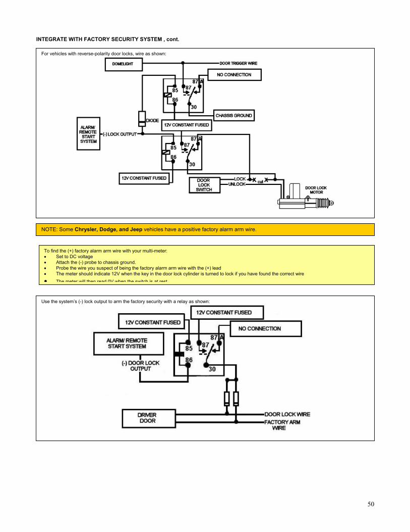
For vehicles with reverse-polarity door locks, wire as shown:
To find the (+) factory alarm arm wire with your multi-meter: Set to DC voltage Attach the (-) probe to chassis ground. Probe the wire you suspect of being the factory alarm arm wire with the (+) lead The meter should indicate 12V when the key in the door lock cylinder is turned to lock if you have found the correct wire
The meter will then read 0V when the switch is at rest
Use the system’s (-) lock output to arm the factory security with a relay as shown:
NOTE: Some Chrysler, Dodge, and Jeep vehicles have a positive factory alarm arm wire.

51
INTEGRATE WITH FACTORY SECURITY SYSTEM , cont.
It will be necessary to disarm the factory security when unlocking the doors. The factory alarm disarm wire must be located and pulsed at the same time as the door unlock wire to disarm the factory security when unlocking the doors.
To find the factory disarm wire with your multi-meter: 1. Set to DC voltage 2. Attach the (-) probe to chassis ground 3. Probe the wire you suspect of being the factory alarm disarm wire 4. When the switch is at rest, the meter should read 12V 5. Unlock the door with the key. The meter should read 0V or close to it. If it does, that is the correct
wire.
For vehicles with negative trigger door locks, wire as shown:
For vehicles with positive trigger door locks wire as shown:
Pictured is the location of the factory alarm disarm wire in the driver’s kick panel in a 1998 Dodge Durango.

52
INTEGRATE WITH FACTORY SECURITY SYSTEM , cont.
Wire as shown:
For 96-98 Jeep Grand Cherokees, use a relay to send a pulse to the door unlock wire and the factory alarm disarm wire to disarm the factory security when unlocking the doors.

53
INTEGRATE WITH FACTORY SECURITY SYSTEM , cont.
Wire as shown:
For 99-Up Jeep Grand Cherokees, use a relay to send a pulse to the door unlock wire and the factory alarm disarm wire through a 463 ohm resistor to disarm the factory security when unlocking the doors.

54
INTEGRATE WITH FACTORY SECURITY SYSTEM , cont.
When installing an aftermarket alarm or remote start with keyless entry, it will be necessary to disarm the factory security system when the doors are unlocked.
For vehicles with reverse-polarity door locks, wire as shown:
To find the (+) factory alarm disarm wire with your multi-meter: 1. Set to DC voltage 2. Attach the (-) probe to chassis ground. 3. Probe the wire you suspect of being the factory alarm arm wire with the (+) lead 4. The meter should indicate 12V when the key in the door lock cylinder is turned to lock if you have found the correct wire 5. The meter will then read 0V when the switch is at rest.
Use the system’s (-) unlock output to disarm the factory security on vehicles with a (+) door unlock wire and a (+) factory alarm disarm wire with a relay asshown:
NOTE: Some Chrysler, Dodge, and Jeep vehicles have a positive factory alarm disarm wire.

55
INTEGRATE WITH FACTORY SECURITY SYSTEM , cont.
It will be necessary on most vehicles to disarm the factory security system when the vehicle is remote started. Take the time to test this by sitting in the car and arming the factory alarm. Wait 2 minutes and try to start the car. If the horn honks and the lights flash when the vehicle is started, the factory security system has been triggered and the remote start system will need to disarm the factory security system when remote starting the vehicle.
For vehicles with a NEGATIVE factory alarm disarm wire, connect the remote start system’s (-)factory alarm disarm wire to the vehicle’s (-) factory disarm wire using a relay as shown:
For vehicles with a POSITIVE factory alarm disarm wire, connect the remote start system’s (-) factory alarm disarm wire to the vehicle’s (+) factory disarm wireusing a relay as shown:
Use the aftermarket system's unlock output to disarm the factory alarm as shown.
On some Mitsubishi vehicles, Factory alarm disarm wire must be relay isolated from the door key cylinder
The shows the location of the factory alarm disarm-no-unlock wire in the harness at the driver’s window switchof a 1999 Honda Accord EX.

56
INTEGRATE WITH FACTORY SECURITY SYSTEM , cont.
To disarm without unlocking the doors: 1. Find the GREEN/YELLOW unlock wire at the factory alarm. 2. Cut the wire and place a diode inline with the stripe away from the factory alarm. 3. Tap between the diode and the factory alarm for your disarm without unlock.
Use a relay and wire as shown:
For a negative disarm through a resistor, wire as shown:
For a positive disarm through a resistor, wire as shown:
NOTE: Many newer Chrysler, Dodge, Plymouth, and Jeep vehicles require a positive trigger or a negative trigger with a resistor in-lineto disarm the factory security when remote starting the vehicle.
NOTE: 1995-1998 Acura TLs arm the factory security system when the doors are locked and disarm when the doors are unlocked. Whenremote starting the vehicle, the factory security system must be disarmed or the factory security system may be triggered.

57
INTEGRATE WITH FACTORY SECURITY SYSTEM , cont.
In order to disarm the factory security when remote starting the vehicle on some vehicles, it is necessary to connect to the vehicle’s key sense wire.
To find the key-sense wire with your multi-meter: 1. Set to DC voltage 2. Attach the (-) probe to chassis ground 3. Probe the wire you suspect of being the key-sense wire 4. When the without the key in the ignition, the meter should read 12V 5. Insert the key in the ignition. The meter should read 0V or close to it. If it does, that is the correct wire.
For 99-Up Galants. Cut the key sense wire and use a relay to wire as shown.
To disarm the factory security by connecting to the (-) key sense wire, wire as shown:
NOTE: When installing a remote start on 99-Up Mitsubishi Galants with factory alarm, must interrupt the BLUE/RED (-) key sense wire at the steering column using the remote start’s (-) output when remote start is activated wire to bypass the factory starter kill.
Pictured above is the location of the key sense wire in a small connector by the ignition key cylinder on a 2001 Toyota 4Runner. On most vehicles, the key sense wire can be found in a small connector near the vehicle’s ignition cylinder.

58
INTEGRATE WITH FACTORY SECURITY SYSTEM , cont.
On some vehicles there is no wire that will disarm the factory security without unlocking the doors. Instead, the remote start must unlock the doors to disarm the factory security system. Once disarmed, use the remote start’s starter wire output to also relock the doors. When the remote start is activated, the doors will unlock and disarm the factory security system. A couple seconds later, the doors will relock as the remote starter cranks the engine to start the vehicle. Diodes must be used to prevent the engine from cranking when the doors are locked.
Follow the diagram below for vehicles with negative triggered doorlocks:

59
INTEGRATE WITH FACTORY SECURITY SYSTEM , cont.
Follow the diagram as shown:
Starting in 1996, some Chrysler, Dodge, and Plymouth minivans were equipped with a factory security system. Generally, the factory security system arms when the doors are locked using the factory remote or key and the factory security system disarms when the doors are unlocked using the factory remote or key. When adding a remote start to vehicles with a factory security system, the doors must be pulsed to unlock the doors and then pulsed to relock the doors.

60
INTEGRATE WITH FACTORY SECURITY SYSTEM , cont.
To turn off the factory security system: 1. Turn the ignition on and then off. 2. Remote the radio fuse only (not the one that says acc/radio) 3. Turn the key to the accessory position. When you do this you will get two chirps from the door buzzer. Should you only hear one chirp, the
vehicle does not have factory security and these instructions do not apply. You must hear two chirps.4. Press the unlock switch on the door. This will give 1-4 chirps depending on the program step. Continue pressing the unlock switch until
you get the desired chirp setting
1 Chirp – Security Off 2 Chirps- Remote Only 3 Chirps- Factory Setting 4 Chirps- Passive Arming
5. Turn the ignition off. 6. Put the radio fuse back in.
1. Locate the factory alarm module. It can be found behind the panel net to the driver’s rear seat. 2. Use a relay to isolate the PINK (ignition input) wire and interface the YELLOW/BLACK (starter kill output) wire as shown using the remote start’s (-) ground when remote started wire. NOTE: This procedure will also allow the factory remotes to function when the vehicle is remote started.
On 1997-1999 Saturn models, there is not an external factory alarm disarm wire. The factory alarm can only be armed and disarmed with the factory remote. In order to keep the factory alarm active when the vehicle is remote started, the following steps must be performed:
Some 96-Up Chevy Camaro and Pontiac Firebird models are equipped with a factory alarm. The only way to disarm these alarms is with the factory remote or turning on the ignition.
It is also possible and sometimes necessary to turn off the factory security system.

61
27. FACTORY IMMOBILIZER BYPASS (Remote Start Installations Only):
Many newer vehicles have a factory Immobilizer system. This type of system uses a small chip imbedded in the ignition key, called a transponder, to transmit a very low powered RF signal. This signal is picked up through an antenna or coil around the ignition switch, which is then sent to the immobilizer's transceiver. Once the correct signal is received, the immobilizer will enable the ignition and/or fuel systems. If an attempt is made to start the vehicle and the transceiver does not receive a valid code, the ignition and sometimes the fuel systems are disable. The immobilizer system will then render the remote start system useless. The immobilizer system needs to be bypassed when doing a remote start.
Installation instructions may vary depending on the brand of the bypass module so it's highly recommended to follow the directions included with the bypass module.
In most cases, an Immobilizer bypass module will be installed this way: 1. Open the module unit and place the vehicle's coded key. 2. Reassemble the unit with the key inside. 3. Carefully disassemble the steering column shroud and place the antenna ring around the ignition switch. 4. The unit will usually have two wires that will need to be connected. One will be connected to 12V constant and the other will need to be hooked up to a
negative (-) output when the vehicle is remote started. This will trigger the unit when the vehicle is remote started and make the vehicle think the key is in the ignition.
5. Test unit before reassembling the steering column. 6. Reassemble the steering column shroud.
Example of an Immobilizer bypass module: Shown below is a grey ignition key of a 2001 Dodge Stratus.1998-Up Chrysler, Dodge, Jeep, and Plymouth vehicles with agrey ignition key are equipped with a factory Immobilizer system.This must be bypassed when installing a remote start system.
Example of a spare key inserted into an Immobilizer bypass module before the module is reassembled and installed with the remote start system.

62
FACTORY IMMOBILIZER BYPASS, cont.
PIN CONNECTION
85 CHASSIS GROUND
86 (+) IGNITION KEY SENSE WIRE
87 NO CONNECTION
87A TO (-) INPUT OF IMMOBILIZER BYPASS MODULE
30 (-) OUTPUT FROM REMOTE START SYSTEM WHEN REMOTE START IS ACTIVATED
To prevent the vehicle from seeing two transponders at the same time on 2001-Up Ford Escapes and Mazda Tributes, use a relay as shown:
On 2001-Up Mazda Tributes and Ford Escapes, use the BLACK/PINK (+) key sense wire at the steering column to interrupt the Immobilizer bypass unit, so that when the key is inserted to do take over the vehicle does not see two transponders at the same time.
Example of the Immobilizer bypass module’s antenna ring placed around the vehicle’s ignition key cylinder.

63
28. EWSII INTERFACE (Remote Start Installations Only):
All BMW vehicles, 1995 and newer, use an Electronic Immobilization System called EWS II. The EWS II system uses an antenna ring around the ignition cylinder to energize a small transponder chip hidden in the key. When the ignition is turned on, this chip is energized and the antenna ring sends the code to the one of the vehicle’s computers. If the code is correct the vehicle is allowed to start and run. If an invalid code is sent, the vehicle will not start. When installing a remote start system, it is necessary to bypass the system while the vehicle is remote started. This interface will allow the system to function normally, still protecting the vehicle, while bypassing the system when remote starting.
This interface will require purchasing one EWS steering wheel lock antenna ring. Part # 66-008362278 from your local BMW dealer. This part generally costs between $20-$30. A spare key is also required. This can be either the ABS emergency key or the standard metal key.
29. PATS (PASSIVE ANTI-THEFT SYSTEM) BYPASS (Remote Start Installations Only):
NOTE: Most 1995-Up Fords, Lincolns, and Mercurys are equipped with PATS (Passive Anti Theft System). The PATS system is a transponder based anti theft system. It uses a very small electronic chip (the PATS capsule) hidden in the top of the key to send a code to the vehicle's transceiver whenever the ignition is energized. For this to happen the key must be placed in the ignition and turned to the RUN position. This energizes a coil surrounding the key, which in turn energizes the chip, which sends the signal to the vehicle. If the vehicle does not "see" the code being sent the car will start and immediately shut off and the anti-theft light in the dash will flash. In order to do a remote start on a PATS-equipped vehicle, a PATS bypass module MUST be used. Installation instructions may vary depending on the brand of the bypass module so it's highly recommended to follow the directions included with the bypass module.
To interface with the EWS II system: 1. At the ignition harness you will find GREEN and PURPLE or (PURPLE/WHITE) wires that need to be energized as ignition wires. 2. Find the two small gauge LT.GREEN wires going between the ignition switch cylinder and the EWS II transceiver module. 3. Wire the relay as shown with the new antenna ring and the key making sure the head of the key is in the middle of the ring.
4. The new antenna ring and the attached key should be well hidden behind the dash area. Try to keep a distance of at least 18 inches between the original ignition ring and the new one to keep the two from interfering with each other.
NOTE: It is recommended that the shaft of the key be cut prior to use so that if found by a thief it will not turn in the ignition cylinder.
In most cases, a PATS bypass module will be installed this way: 1. Install the remote start and make the proper wire connections to the bypass module. Usually,
there is one wire that is connected to 12V Constant and another wire is hooked up to an outputfrom the remote start that gives a negative (-) pulse when the vehicle is remote started.
2. Remove the steering column shroud. There should be a plastic ring surrounding the ignitionswitch. This is the coil or antenna ring. Connected to the antenna ring through a rubber coatedribbon cable is a small black box. This is the PATS transceiver. Locate these parts.
3. From the PATS bypass module is a PATS capsule. Attach the PATS capsule to the PATSantenna ring using a wire tie. Be careful with the placement of the PATS capsule and keep inmind that the steering column shroud must go back on after installation is successful andcomplete.
4. With an ignition key, turn the ignition to the RUN position for one second, then turn the ignitionoff and remove the key.
NOTE: In some instances it may be required to turn the ignition to the RUN position until the "theft"light in the dash turns off. 5. With a second key, turn the ignition to the RUN position for one second, and then turn the
ignition off. This must be done within 5 seconds of removing the last key. NOTE: In some instances it may be required to turn the ignition to the RUN position until the "theft"light in the dash turns off. 6. Within 10 seconds remote start the vehicle. 7. If the vehicle starts and continues running and the THEFT light in the dash goes out, installing
the PATS capsule has been done successfully. If the vehicle cranks and does not start, and theTHEFT light is blinking, the PATS capsule was not successfully learned. Repeat steps 4-6again. If the vehicle still does not start, it may be necessary to relocate the PATS capsule.
Shown below is the ignition key of a 2000 Ford Expedition equipped with the PATS anti-theft system. Ford vehicles equipped with PATS will have a large ignition key similar to the one shown below.

64
30. PASSKEY (VATS) BYPASS (Remote Start Installations Only):
Vehicles with the GM VATS system have a resistor embedded in the ignition key. If the VATS decoder module does not measure the proper resistance when the vehicle is started, the starter and/or fuel pump may be disabled for up to 10 minutes. The VATS wires will be two very light-gauge wires coming out of the steering column. The colors of the wires vary, but are often contained in orange, black, or gray tubing. Determine the value of the resistor in the key. Then follow the diagram to bypass VATS during remote start operation.
General Motors only uses a fixed number of different resistors with the VATS system. The resistance of the chip in the ignition key should correspond with one of these following values.
390 Ohms 520 Ohms 680 Ohms
885 Ohms 1130 Ohms 1470 Ohms
1800 Ohms 2370 Ohms 3010 Ohms
3740 Ohms 4750 Ohms 6040 Ohms
7500 Ohms 9530 Ohms 1180 Ohms
NOTE: When connecting to the VATS wires it is not important which wire is cut but make sure that the key side of the cut wire goes toterminal 87a of the relay and the car side of the cut wire goes to terminal 30:

65
31. PASSLOCK I BYPASS (Remote Start Installations Only):
The Passlock I system consists of four parts: the Passlock key cylinder, the ignition switch, the instrument cluster panel (IPC) and the power train control module (PCM). The system requires that the key cylinder be mechanically turned using a key. When the key cylinder is properly turned, it generates a resistance code (R-code), which is sent to the IPC. The Passlock system must see the correct resistance code at the correct time. When the ignition switch is turned to the crank position, the “Bulb Check” Wire is switched to ground. This starts a time window during which the IPC analyzes the R-Code. If the R-code is valid and is received in the proper window of time, the IPC sends a code via data bus to the PCM to enable the fuel injection system. If the key cylinder itself is pulled out or damaged, it will not generate the resistance code and the vehicle will not run. Note that the Passlock system will let the car crank and possibly run for a short time before the fuel injectors shut off.
The picture on the left shows the 3-wire Passlock cable from the ignition cylinder of a 1997 Pontiac Sunfire. Notice the 3-wire cable changes colors from BLACK, BLACK, and BLACK/WHITE to BLACK, YELLOW, and WHITE.
The picture above shows the bulb check wire in the ignition harness of a 1997 Pontiac Sunfire.
1.Locate “Bulb Check” wire, which is a black wire in top ignition switch plug.
NOTE:This wire will test positive when key cylinder is turned to the on position and test ground when the key cylinder is turned to the crank position.
2. Locate three-wire ribbon cable from Passlock key cylinder 3. Cut yellow (black) wire in position three of the ribbon cable. 4. Turn the ignition on. 5. Use a digital multi-meter to read the R-code across the key side of the yellow (black) wire and the black (black wire)
It is strongly recommended that a Passlock I Bypass module is purchased and used for this process.

66
PASSLOCK I BYPASS , cont.
Interface with the bulb check wire and ribbon cable as shown below.

67
32. PASSLOCK II BYPASS (Remote Start Installations Only):
98 and up Chevy and GMC trucks come equipped with a Passlock passive anti-theft system. The Passlock system uses a sensor inside the ignition switch that creates a resistance code (R-Code) when the key cylinder is rotated. When attempting to start the vehicle, the R-Code must be present of the vehicle immediately shuts down. When installing a remote starter in a GM vehicle equipped with Passlock 2, a bypass module or two relays must be used.
(LEFT) Shown is the location of the Passlock II wires (18 gauge YELLOW and ORANGE/BLACK) in the ignition harness of a 1998 Chevy Suburban. 1998-2002 Chevy and GMC full-size trucks and SUVs will be similar. BE CAREFUL WORKING AROUND AIRBAG WIRES, which can be found in yellow split loom or tubing in the ignition harness.
(LEFT) Shown is the location of the Passlock II wires (YELLOW and BLACK) in a 2003 Chevy Tahoe.
Setting the multi-meter to test resistance, the correct R-Code can be found 1. Interrupt the starter wire. This is important since testing requires turning the key to the crank position. If the vehicle is accidentally started while testing
with the yellow Passlock wire cut, the system may enter "Fail-enable" mode. In Fail-Enable mode. The vehicle sees an open connection in the systemand will start but the "Theft Warning" light stays constantly illuminated. If the system enters Fail-Enable mode, it must be reset by the car dealer.
2. Interrupt the YELLOW Passlock wire in the ignition harness of the vehicle. 3. Connect the (+) lead of the multi-meter to the ignition side of the YELLOW Passlock wire. 4. Locate the other Passlock wire in the ignition harness. This wire is ORANGE/BLACK in trucks and SUVs. Without interrupting this wire, connect the (-)
lead of the meter to this wire. NOTE: Avoid touching the two Passlock wires together. Touching them together can give false readings.
5. Turn the key to the CRANK position. The meter will show the correct resistor value or R-Code.

68
PASSLOCK II BYPASS, cont.
NOTE: A bypass module is highly recommended, as it is much easier and more convenient to install than using relays. But to userelays follow the diagram below:

69
33. PASSKEY III BYPASS:
Some newer GM vehicles have a factory Passkey III Immobilizer system. This type of system uses a small chip imbedded in the ignition key, called a transponder, to transmit a very low powered RF signal. This signal is picked up through an antenna or coil around the ignition switch, which is then sent to the immobilizer's transceiver. Once the correct signal is received, the immobilizer will enable the ignition and/or fuel systems. If an attempt is made to start the vehicle and the transceiver does not receive a valid code, the ignition and sometimes the fuel systems are disable. The immobilizer system will then render the remote start system useless. The immobilizer system needs to be bypassed when doing a remote start.
Installation instructions may vary depending on the brand of the bypass module so it's highly recommended to follow the directions included with the bypass module.
In most cases, an Immobilizer bypass module will be installed this way: 1. Open the module unit and place the vehicle's coded key. 2. Reassemble the unit with the key inside. 3. Carefully disassemble the steering column shroud and place the antenna ring around the ignition switch. 4. The unit will usually have two wires that will need to be connected. One will be connected to 12V constant and the other will need to be hooked up to anegative (-) output when the vehicle is remote started. This will trigger the unit when the vehicle is remote started and make the vehicle think the key is in theignition. 5 Test unit before reassembling the steering column. 6 Reassemble the steering column shroud.
To prevent the vehicle from seeing two transponders at the same time on 99-Up Pontiac Montanas, Oldsmobile Silhouettes, and Chevy Ventures, use a relay as shown:
On 99-Up Pontiac Montanas, Oldsmobile Silhouettes, and Chevy Ventures, use the LT. GREEN (-) key sense wire at the steering column to interrupt the Passkey bypass unit, so that when the key is inserted to do take over the vehicle does not seetwo transponders at the same time.

70
34. DIESEL VEHICLES/ WAIT-TO-START INPUT (Remote Start Installations Only):
Most remote start systems have the ability to be installed on a diesel vehicle. Check the installation manual included with the remote start system. Some systems can simply be programmed to be compatible with a diesel vehicle. Other systems have a (-) WAIT-TO-START INPUT wire that must be connected to be compatible with a diesel vehicle. For systems with a (-) WAIT-TO-START INPUT wire it is necessary to interface with the wire that turns on the WAIT-TO-START light in the dashboard. This wire illuminates the bulb until the vehicle's glow plugs are properly heated. When the light goes out the vehicle can be started. This wire is always available at the connector leading to the bulb in the dashboard.Connect this wire from the remote start system to the wire in the vehicle that sends the signal to turn on the WAIT-TO-START bulb in the dashboard.
To find the (+) WAIT-TO-START wire 1. Set the multi-meter to DC voltage. 2. Attach the (+) probe to 12V Constant 3. Probe the wire you suspect leads to the bulb with the (-) probe of the meter 4. Turn the ignition to the ON position 5. If the meter reads 0V until the light goes out and then reads 12V that is the correct wire.
To find the (-) WAIT-TO-START wire 1. Set the multi-meter to DC voltage. 2. Attach the (+) probe to 12V Constant 3. Probe the wire you suspect leads to the bulb with the (-) probe of the meter 4. Turn the ignition to the ON position 5 If the meter reads 12V until the light goes out and then reads 0V that is the correct wire
For vehicles with a (+) WAIT-TO-START wire, use a relay and wire as shown.
For vehicles with a (-) WAIT-TO-START wire, use a relay and wire as shown:
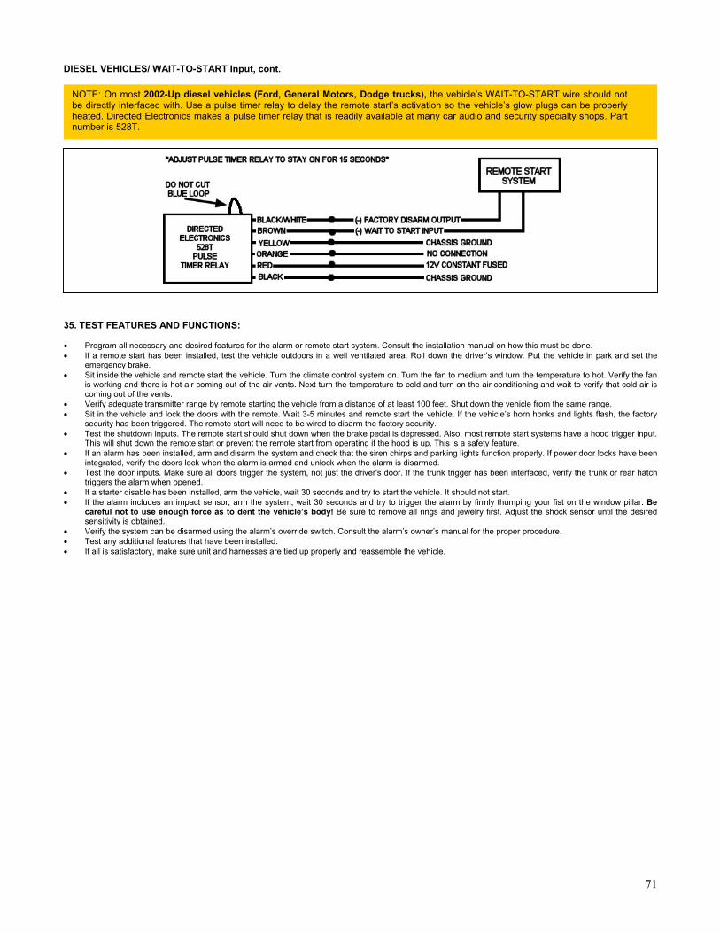
71
DIESEL VEHICLES/ WAIT-TO-START Input, cont.
35. TEST FEATURES AND FUNCTIONS:
Program all necessary and desired features for the alarm or remote start system. Consult the installation manual on how this must be done. If a remote start has been installed, test the vehicle outdoors in a well ventilated area. Roll down the driver’s window. Put the vehicle in park and set the emergency brake. Sit inside the vehicle and remote start the vehicle. Turn the climate control system on. Turn the fan to medium and turn the temperature to hot. Verify the fan is working and there is hot air coming out of the air vents. Next turn the temperature to cold and turn on the air conditioning and wait to verify that cold air is coming out of the vents. Verify adequate transmitter range by remote starting the vehicle from a distance of at least 100 feet. Shut down the vehicle from the same range. Sit in the vehicle and lock the doors with the remote. Wait 3-5 minutes and remote start the vehicle. If the vehicle’s horn honks and lights flash, the factory security has been triggered. The remote start will need to be wired to disarm the factory security. Test the shutdown inputs. The remote start should shut down when the brake pedal is depressed. Also, most remote start systems have a hood trigger input. This will shut down the remote start or prevent the remote start from operating if the hood is up. This is a safety feature. If an alarm has been installed, arm and disarm the system and check that the siren chirps and parking lights function properly. If power door locks have been integrated, verify the doors lock when the alarm is armed and unlock when the alarm is disarmed. Test the door inputs. Make sure all doors trigger the system, not just the driver's door. If the trunk trigger has been interfaced, verify the trunk or rear hatch triggers the alarm when opened. If a starter disable has been installed, arm the vehicle, wait 30 seconds and try to start the vehicle. It should not start. If the alarm includes an impact sensor, arm the system, wait 30 seconds and try to trigger the alarm by firmly thumping your fist on the window pillar. Becareful not to use enough force as to dent the vehicle’s body! Be sure to remove all rings and jewelry first. Adjust the shock sensor until the desired sensitivity is obtained. Verify the system can be disarmed using the alarm’s override switch. Consult the alarm’s owner’s manual for the proper procedure.Test any additional features that have been installed. If all is satisfactory, make sure unit and harnesses are tied up properly and reassemble the vehicle.
NOTE: On most 2002-Up diesel vehicles (Ford, General Motors, Dodge trucks), the vehicle’s WAIT-TO-START wire should not be directly interfaced with. Use a pulse timer relay to delay the remote start’s activation so the vehicle’s glow plugs can be properly heated. Directed Electronics makes a pulse timer relay that is readily available at many car audio and security specialty shops. Part number is 528T.