vs2 release 3
TRANSCRIPT

Systems
GC28-0681-2 File No. S370-34
--
OS/VS2 System Programming Library: Initialization and Tuning Guide
VS2 Release 3.7

Third Edition (January, 1976)
This edition is a major revision of, and obsoletes, GC28-0681-1 and Technical Newsletter GN28-2603. See the Summary of Amendments following the Contents. Changes or additions to the text and illustrations are indicated by a vertical line to the left of the change.
This edition applies to Release 3.7 of OS/VS2 and to all subsequent releases of OS/VS2 until otherwise indicated in new editions or Technical Newsletters. Changes are continually made to the information herein; before using this publication in connection with the operation of IBM systems, consult the latest IBM System!370 Bibliography, GC20-0001, for the editions that are applicable and current.
Requests for copies of IBM publications should be made to your IBM representative or to the IBM branch office serving your locality.
A form for readers' comments is provided at the back of this pUblication. If the form has been removed, comments may be addressed to IBM Corporation, Publications Development, Department D58, Building 706-2, PO Box 390, Poughkeepsie, N.Y. 12602. Comments become the property of IBM.
©Copyright International Business Machines Corporation 1974, 1975, 1976

Preface
This book is effectively two manuals in one: a system initialization SRL and a preliminary tuning gUide. These two "manuals" are combined because of the need for heavy cross referencing between performance discussions and the descriptions of parameters and parmlib members that affect performance. The book is a pioneer effort in both areas: how to initialize the system, and how to get improved system performance. For best results, you should read this manual before you prepare your sysgen deck.
Although it is basically an SRL, elements oflogic are included for certain components: the System Resources Manager (SRM), the Auxiliary Storage Manager (ASM), and to some extent NIP and the Program Manager. The logic elements are provided either to clarify recommendations and "how it works" descriptions, or to provide a basis for possible internal modification. This is especially true of the chapter on the System Resources Manager.
The manual consists of five parts or chapters.
• Part 1: Introd uction • Part 2: System Initialization • Part 3: How to Use the System Resources Manager • Part 4: How to Use the System Activity Measurement Facility (MF/l) • Part 5: System Performance Factors
Part 2, System Initialization, describes parmlib parameters and processes related to IPL, and certain system commands (START GTF, START MFl, SET IPS). It includes the meaning and use of each parameter, syntax rules, syntax examples, value ranges that are syntactically acceptable, default values, and performance notes where applicable. The chapter points the reader to extended discussions on related topics in Parts 3,4, and 5. Part 2 also describes the IBM-supplied default Installation Performance Specification (IPS) and gives the philosophy on which its values are based.
Part 3 is a combined SRL and high-level "PLM" on the System Resources Manager (SRM). It gives the SRM's basic design philosophy, describes the external parameters of parmlib members IEAIPSxx and IEAOPTxx by which the SRM can be adjusted, briefly discusses the Resource Use routines, and describes the internal constants that control various threshold levels. The use of the parameters in the two parmlib members is explained and illustrated by many examples. These parameters are also listed for easy reference in Part 2, System Initialization.
Part 4 is a small "SRL" on the use of the System Activity Measurement Facility, MF /1. The chapter describes the parameters that control MF /1 reports and SMF records, discusses how MF /1 can be started (including the IBM -supplied cataloged procedure) and provides some possible uses for each of the system activity reports.
Part 5 discusses a number of system performance areas and three measurement tools. The following topics are covered:
• Guidelines for the Effective Use of Paging Data Sets • The Pageable Link Pack Area: Its Advantages and Uses
• VIO Performance • Device Allocation Performance
,• VSAM Catalog Performance • How SMF Can Supplement MF/l • The Use of GTF to Track Sysevents
Preface 3

• TCAM Tuning Considerations • TSO and Batch Service Trade-offs Via the IPS • Miscellaneous Performance Guidelines
The performance factors information in Part 5, plus performance hints in othel parts of the manual, are preliminary projections based on design analysis. That is, the information is based on the designers' best judgement of how the system should behave and the factors that should affect its performance. This preliminary performance information will be updated by Installation Newsletters after the manual is printed. The updates will provide tuning gUidelines based on system measure men ts.
Several of the performance topics in Part 5 use an experimental technique: inclusion of customer questions asked on these topics, followed by the answers.
Related Publications
The folloWing manuals should be available for reference while you are reading this SRL:
OSjVS System Management Facilities (SMF)
OSjVS Utilities
OSjVS2 Using OS Catalog Management with the Master Catalog: CVOL Processor
OSjVS2 System Programming Library: System Generation Reference
OSjVS2 Access Method Services
OSjVS Virtual Storage Access Method Programmer's Guide
OSjVS2 TCAM Programmer's Guide
OSjVS System Programming Library: VTAM
Operator's Library: OSjVS2 Reference (JES2)
OSjVS2 System Programming Library: JES2
OSjVS2 System Programming Library: JES3 System Programmer's Guide
Operator's Library: OSjVS2 Reference (JES3)
Operator's Library: OSjVS2 TCAM
OSjVS2 Supervisor Services and Macro Instructions
OSjVS2 System Programming Library: Job Management
OSjVS2 System Programming Library: Supervisor
OSjVS2 System Programming Library: TSO
OSjVS2 System Programming Library: Storage Estimates
OSjVS2 System Programming Library: Service Aids
OSjVS2JCL
OSjVS Message Library: VS2 System Messages
OSjVS Message Library: JES3 Messages
OSjVS2 System Programming Library: Data Management
OSjVS2 Conversion Notebook
OSjVS Mass Storage System (MSS) Services for Space Management
IBM Systemj360 and Systemj370 ASP Version 3 Asymmetric Multiprocessing System: System Programmer's Manual
ASP Version 3 Operator's Manual
4 OS!VS2.system Programming Library: Initialization and Tuning Guide (VS2 Release 3.7)
GC35·0004
GC35-0005
GC35-0010
GC26-3792
GC26-3841
GC26-3838
GC30-2041
GC28-0688
GC38-0210
GC23-0001
GC28-0608
GC38-0226
GC30-2046
GC28-0683
GC28-0627
GC28-0628
GC28-0629
GC28-0604
GC28-0674
GC28-0692
GC38-1002
GC38-1012
GC26-3830
GC28-0689
GC35-0012
GH20-1292
GH20-1289

Contents
Summary of Amendments . 9
Put 1: General Introduction 13
Part 2: System Initialization 19 Initialization Overview . 20 Descriptions of Individual PARMLIB Members 41
COMMNDxx. 41 GTFPARM 43 IEAABDOO 48 IEAAPFxx 52 IEAAPPOO 53 IEABLDxx 56 IEADMPOO 58 IEAFIXxx 61 IEAIPSxx 63 IEALODOO 72 IEALPAxx 73 IEAOPTxx 75 IEAPAKOO 78 IEASYSxx 85 IKJPRMOO 130 IRBMFlxx 134 LNKLSTxx 139 MVIKEYOO 140 PARMTZ. 143 SMFPRMxx 145 VATLSTxx 151
Part 3: How to Use the System Resources Manager ....................... 159 Description of the System Resources Manager (SRM) ...................... 159
The Workload Manager ........•............................ 160 Resour.ce Use Routines ..................................... 166 The SRM Control Routine . . . . . . . . . . . . . . . . . . . . . . . . . . . . . . ..... 170
Contents 5

-- -------------
How the System Resources Manager Is Controlled IEAIPSxx - IPS Parameters ........ . IEAOPTxx - System Tuning Parameters .. Other SRM Constants ............ .
Guidelines for Defining SRM Parameters ... . Changing the Installation Performance Specification (PARMLIB member IEAIPSxx). Changing the System Tuning Parameters (PARMLIB member IEAOPTxx) .
Part 4: How to Use the System Activity Measurement Facility (MF/l) MF/1 Operation ....... . MF/I Options ............................. .
Conflicts Between Options . . . . . . . . . . . . . . . . . . . .. Need for Careful Choice of Certain Parameters and Options ..
MF/I Reports and SMF Records. CPU Activity Report Channel Activity Report .. I/O Device Activity Reports Paging Activity Report .. Workload Activity Report .
Using MF/l ........... . Using the CPU Activity Report Using the Channel Activity Report Using the Device Activity Report . Using the Paging Activity Report Using the Workload Activity Report
Part 5: System Performance Factors . . Guidelines for the Effective Use of Paging Data Sets
How ASM Handles Paging Read and Write Requests Questions and Answers ......... . . . . . .. .
The Pageable Link Pack Area: Its Advantages and Uses Recommendations ........ . The VS2 Module Search Sequence . How the PLP A is Loaded
VIO Performance Advantages ....... . Disadvantages. . . . .. . VIO Performance Considerations . How to Specify VIO Data Sets Questions and Answers ....... .
Device Allocation Performance The Order in Which Allocation Requests Are Serviced Guidelines for Improving Allocation Response ..... .. TSO Allocation Suggestions ................. . How the SRM Allocation Algorithm Supports I/O Load Adjusting Questions and Answers .
VSAM Catalog Performance .... . Questions and Answers ...... ..... .
How SMF Can Supplement MF/l .. . ...... . Comparison of Paging Rates for a Problem Program and the System . Comparison of I/O Activity for a Problem Program and the System Comparison of Problem Program Service and Total Service Determining Changes to the System Configuration .
The Use of GTF to Track Sysevents ............... . TCAM Tuning Considerations ................... .. .
Packaging the MCP to Minimize Page Fixes and Page Faults '" Coding INTRO Operands to Minimize Fixed Pages .......... .. Ordering OPEN Macros to Minimize Fixed Pages for LCBs and SCBs ..
TSO and Batch Service Trade-offs Via the IPS Miscellaneous Performance Guidelines
Index .................. .
6 OS/VS2 System Programming Library: Initialization and Tuning Guide (VS2 Release 3.7)
170 172
~ 181 182 188 188 201
203 203 205 207 207 209 210 212 215 216 220 224 224 225 226 227 228
231 231 237 238 240 240 243 243 246 246 248
248 249 250 252 252 253 255 255 256 257 260 261 261 262 262 262 263 294 294 296 299 302 303
305
:J

Figures
Figure 2-l. Parmlib Members: Relationships to IPL Parameters and Sysgen Figure 2-2. Parameters (Part 1 of 2) 25 Figure 2-3. Characteristics of Parmlib Members (Part 1 of 8) 27
Example of Adding and Replacing Parmlib Members by Means Figure 2-4. of the IEBUPDTE Utility 35 Figure 2-5. Mutually Exclusive Options for GTFPARM . 45
Performance Objectives in IBM-Supplied IPS. 66 Figure 2-6. Default Pack List for Time Sharing and Batch System 80 Figure 2-7. Default Pack List for Batch System 81 Figure 2-8. Functional Contents of Default Pack Lists (Part 1 of 3) 82 Figure 2-9. Sysgen Parameters That Are Copied to the IEASYSOO Member 85 Figure 2-10. Overview of IEASYSxx Parameters (Part 1 of 2) 87
Figure 3-1. Specifying Different User Treatments via Performance Objectives 161 Figure 3-2. Comparing User Treatment via "Normalized" System Workload . 162 Figure 3-3. Associating a TSO Terminal Session with Performance Objectives 165 Figure 3-4. Graph of Performance Objective 3 177 Figure 3-5. Linear Extrapolation of a Performance Objective 178 Figure 3.6 .. "3/2" Scale Extrapolation of a Performance Objective. 178 Figure 3-7. SRM Constants Related to the Resource Use Routines (part 1 of 4) 183 Figure 3-8. SRM Constants Related to the Workload Manager and Control 187 Figure 3-9. Sample Performance Objectives 190 Figure 3-10. Illustration of Key Workload Levels for a Performance Objective. 193 Figure 3-11. illustration of Different Performance Objective Cut-offs 193 Figure 3-12. Raising a Performance Objective 194 Figure 3-13. IPS AA 197 Figure 3-14. IPS BB 198 Figure 3-15. Effect of an Increase in Service Definition Coefficients 200
(. Figure 4-1. CPU Activity Report 211 Figure 4-2. Channel Activity Report 214 Figure 4-3. Direct Access Device Activity Report 214 Figure 4-4. Paging Activity Report. 219 Figure 4-5. Workload Activity Report (Part 1 of 2) 222 Figure 4-6. Variation of System Workload Level with Time of Day 229
Figure 5-l. lllustration of the Loading of the PLPA . 245 Figure 5-2. SRM Trace Record Format 263 Figure 5-3. Descriptions of SYSEVENT Codes (Part 1 of 24) 265 Figure 5-4. Sysevents Sorted by Address Space ID and by Time of Day (part 1 of 2) 289 Figure 5-5. Time Distribution Between Sysevents of Same Type 291 Figure 5-6. Distribution of Time Needed to Complete a Swapout . 292 Figure 5-7. Instances of Real Frame Shortages, Distributed by Time of Day 293 Figure 5-8. Distribution of Real Frame Shortages 293 Figure 5-9. Available Buffer Units and CPBs According to UNITSZ Operand. 299 Figure 5-10. LCB Sizes by Terminal Type 300
Contents 7

8 OS/VS2 System Programming Library: Initialization and Tuning Guide (VS2 Release 3.7)

Summary of Amendments for GC28-0681-2 VS2 Release 3.7
The JES2 and JES3 Initialization sections and the JES2 Performance sections are no longer in this manual. For information about JES2 and JES3, refer respectively to OS/VS2 System Programming Library: JES2, GC23-0001, and OS/VS2 System Programming Library: JES3, GC28-0608.
Changes have been made throughout this publication to reflect a Service Update - -OS/VS2 Release 3.7. In addition to general editorial changes, technical updated topics include:
• How to Control Parmlib
• Descriptions of Individual Parmlib Members:
- COMMNDxx - IEABLDxx - IEALPAxx - IEASYSxx - LNKLSTxx - MVIKEYOO - VATLSTxx
• I/O Load Adjusting Routine
• Main Storage Occupancy Routine
• Page Replacement Routine
• Device Allocation Routine
• How the System Resources Manager is Controlled
• Performance Objectives
• SRM Constants Related to the Resource Use Routines
• MF /1 Options
• Guidelines for the Effective Use of Paging Data Sets
• Pageable Link Pack Area
• Device Allocation Performance
• VSAM Catalog Performance
• The Use of GTF to Track Sysevents
Summary of Amendments 9

Summary of Amendments for GC28-0681-1 as Updated by GN28-2603 VS2 Release 3
This Technical Newsletter, a part of release 3 of OSjVS2, updates the initialization information for the Job Entry Subsystem 3 (JES3). In addition to general editorial changes, the following topics were technically updated:
• • • • • • • • • • • • • • • • • •
How to Control JES3 Initialization How JES3 Performs Initialization Creating an Initialization Data Set BUFFER CIPARM CLASS DEVICE DYNALLOC (new initialization card) JES3LIB MAINPROC OPTIONS PROC RESCTBLK (new initialization card) RJPTERM SELECT SETNAME STANDARDS SYSOUT
Summary of Amendments for GC28-0681-1 VS2 Release 3
• Mass Storage System (MSS) adds a new member, MVIKEYOO, to SYSl.PARMLIB. MSS also adds the PURGE parameter and causes changes to the VAL parameter in the IEASYSxx member of SYS 1.PARMLIB.
• Multi-Access Spool adds three new JES2 initialization parameters: &CHKPT, QCONTROL, and Sn.
• JES3 Initialization is a new section that explains how to initialize JES3 and describes the JES3 initialization cards and their parameters.
• Vary Storage adds a new parameter, RSU, to the IEASYSxx member of SYSl.PARMLIB. RSU allows the installation to specify the number of storage units that will be available for storage reconfiguration in an MP system.
• Minor technical changes and additions were made throughout the publication.
Note: JES3 and Mass Storage System information contained in this publication is for planning purposes only until the products become available.
10 OS/VS2 System Programming Library: Initialization and Tuning Guide (VS2 Release 3.7)

This Technical Newsletter provides:
Summary of Amendments for GC28-0681-1 as Updated by GN28-2586 VS2 Release 2
• New IBM-supplied default Installation Performance Specifications (IPS).
• Changes to many of the SRM examples and explanations in "Part 3: How to Use the System Resources Manager" because of the new default IPS.
• Changes to the Auxiliary Storage Manager (ASM) slot sorting algorithms for paging data sets. Also, an expanded explanation of how the PAGE parameter is used by ASM.
• New tuning guidelines, some of which were previously printed in IBM Installation Newsletter Issue 74-09 (7/12/74).
• Corrections of minor technical and typographical errors.
Summary of Amendments II
12 OS/VS2 System Programming Library: Initialization and Tuning Guide (VS2 Release 3.7)

Part 1: General Introduction
This manual discusses the following four general subject areas:
• System initialization • The System Resource Manager • The System Activity Measurement Facility (MF /1) • System Performance Factors
System Initialization
System Initialization is the part of system tailoring that takes place after sysgen. The tailoring results from the specification of system parameters, first at IPL and then later when certain operator commands are issued.
System tailoring is the overall process by which an installation selects its operating system. The process consists of the specification of system options through these mechanisms:
• System generation • IPL-time selections • Certain operator commands after IPL • Implicit system parameters
IPL-time choices that help to tailor the system can come from several sources:
• Various types of IPLs. • Operator entry of parameters from the console. • SYSl.PARMLIB. This data set is one of the main sources oflPL-time
parameters. • The JES2 or JES3 initialization data set.
There are several general types of IPL:
• The first IPL after sysgen. This is a "cold" start for NIP. • Any IPL at which the LPA is reloaded. From the NIP viewpoint this is a
"cold" start. • An IPL after power-up ("quick" start). • An IPL after a system crash (''warm'' start).
Operator Entry of Parameters: The operator responds to NIP's SPECIFY SYSTEM PARAMETERS message after he IPLs the system. His response directs NIP, Master Scheduler Initialization, and other components to the desired parmlib members. The operator can enter either ENTER or END* to default to the basic general parameter list IEASYSOO, or enter SYSP=(aa,bb ... ) to select one or more alternate general parameter lists, such as IEASYSO 1 , IEASYS02, etc. The alternate lists can supplement or partially override the basic list. The operator need not enter parameter values directly, except for those cases in which parameters are missing, are syntactically invalid, can't be read, or must be supplemented to satisfy a special case. (An example of a special case would be the operator entry of the PAGE parameter to increase the amount of paging space on direct access.)
*ENTER is used with the Model 158, END with the Model 168.
Part 1: General Introduction 13

If an error occurs with certain parmlib members, the operator is prompted to manually enter one or more of the member's parameters. If the operator can't correct a parameter, he can use ENTER or END on the console. ENTER or END causes selection of system defaults if they exist. Most parameters have defaults, either as 'iefault parmlib members, or as coded values in system components. If a default doesn't exist, ENTER or END cancels the parameter. (The defaults are listed in the individual descriptions of parmlib members later in Part 2, System Initialization. )
An operator-entered parameter overrides the same parameter specified in parmlib member IEASYSOO or IEASYSxx, except for:
• A parameter in which operator intervention is prohibited (OPI=NO). In this case, the operator-entered parameter is ignored unless the parmlib parameter was invalid.
• The PAGE parameter. The page data-set names entered by the operator are added for the life of the IPL to those specified in either IEASYSOO or IEASYSxx. (For information on the PAGE parameter, refer to the description of member IEASYSxx in Part 2.)
The Use of SYSl.PARMLIB: SYSl.PARMLIB is read by NIP and Master Scheduler Initialization at IPL, and later by such components as the System Resource Manager, the noc, GTF, and MF/l, which are invoked by operator command. * The purpose of parmlib is to provide many initialization parameters in a prespecified form in a single data set, and thus minimize the need for operator entry of parameters.
Parmlib contains both a basic or default general parameter list, IEASYSOO, and possible alternate general parameter lists, called IEASYSaa, IEASYSbb, etc. Parmlib also contains specialized members, such as COMMNDxx, PARMTZ, IEALPAxx. The general parameter list(s) contain both parameter values and "directors". The directors (e.g., MLPA=Ol) point or direct NIP or Master Scheduler Initialization to one or more specialized members, such as IEALPAOI.
* The TIOC is the Terminal I/O Coordinator, whose parameters are described under member IKJPRMOO. GTF is the Generalized Trace Facility, whose parameters are described under member GTFPARM. Lastly, MF /1 is the System Activity Measurement Facility, which is described in Part 4, "How to Use the System Activity Measurement Facility (MF /1)".
14 OS/VS2 System Programming Library: Initialization and Tuning Guide (VS2 Release 3.7)

System Tailoring Through Operator Commands: After IPL, several operator commands provide additional system tailoring by directing particular groups of parameters to specific system components. The commands consist of:
• Stop and start JES2 ($p JES2 and $S) • START tcamproc • MODIFY tcamproc • SET IPS • STARTGTF • START MFI • START vtamproc
The System Resources Manager
To a large degree, the control which an installation exerts over the functioning of the MVS system is exercised through the mechanism of the System Resources Manager (SRM). Part 3 describes the functioning of the SRM, the parameters which control its functioning, and guidelines for defining these SRM parameters.
The System Resources Manager (SRM) is a new component in the MVS control program. The SRM has two principal objectives:
• First, to attempt to optimize the use of the system's CPU, storage and I/O resources by system users (address spaces). This is primarily a system throughput consideration.
• Second, to distribute the system's processing resources among individual address spaces in a way that satisfies the installation's response and turnaround time objectives.
These objectives are the concerns of the SRM's Resource Use routines and Workload Manager, respectively. The SRM Control function integrates these objectives into individual swap decisions.
The principal tool of the SRM in attempting to meet these objectives is address space swapping. The effectiveness of swapping in meeting the goal of maintaining resource utilization within acceptable levels depends largely on the variety of candidates for swap-in available at the time it is determined to swap out a user, on the advice of the Resource Use routines. This is one reason that installations should normally operate with more address spaces initiated than can simultaneously fit in real storage. Similarly, a strategy of "overinitiating" permits the SRM's Workload Manager to follow installation response and turnaround time objectives by swapping. (See the discussion on overinitiating in the "JES2 Performance" topic in OS/VS2 System Programming Library: JES2.)
In addition to address space swapping, the SRM uses three other means to achieve its ends:
• Page stealing (disassociating a page from an address space's working set that has gone unreferenced for a sufficient interval)
• Address-space dispatching-priority changes • Device allocation decisions
These mechanisms are related to the SRM's throughput goals, and are discussed under the heading "Resource Use Routines" in Part 3, "How to Use the System Resource Manager."
Part 1: General Introduction 15

The System Activity Measurement Facility (MF /1)
The System Activity Measurement Facility (MF /1) is an analysis tool which an installation may use to monitor selected areas of system activity, and to obtain feedback in the form of SMF records and/or formatted reports. MF /1 permits the gathering of information on the following classes of system activity, either individually or in combination:
• CPU activity
• Channel activity and channel-CPU overlap activity
• I/O device activity and contention for: Unit record devices Communication equipment Graphics devices Magnetic tape equipment Direct access storage devices Character reader equipment
16 OS/VS2 System Programming Library: Initialization and Tuning Guide (VS2 Release 3.7)

• Paging activity
• Workload activity
With MF/ 1, an installation can monitor the utilization of individual CPU's, channels and devices, in order to identify system components whose overall utilization is exceptional. The installation can further identify periods of system activity during which the utilization ofparticuiar resources is exceptional. Finally, the installation can relate the service being provided to different classes of users to the specifications provided in the Installation Performance Specification (IPS).
MF/l is a software monitoring tool. Thus it is limited to reporting on system activity as that activity is communicated to the system (for example, by the setting of flags). As a result of this indirect reporting, MF /1 can approach in accuracy, in its statistically sampled values, only the internal indications of external system activity. For example, if a CPU is disabled so that the freeing of a device (deviceend interruption) cannot be communicated to the system, the device will appear busy for a longer period of time than it would if it were measured by a hardware measuring instrument.
MF /1 is always generated with the system, but its operation is completely optional. The system operator initiates MF/l monitoring with the START command. MF/l can also be started as a batch job. When MF/l is not operating, it will cause little performance or storage overhead. When MF/l is operating, the storage and performance overhead depend on the set of options that were specified.
In an installation using the Mass Storage System (MSS), Mass Storage System Trace Report programs are used to monitor the MSS. These programs are described in OS/ VS Mass Storage Sys tern (MSS) Services for Space Management.
System Performance Factors
Part 5 contains discussions of factors that affect system performance and discussions of certain tools that can measure performance. Each discussion includes gUidelines and rationale. Some discussions also include questions and answers. Since MVS is significantly different from MVT, the discussions emphasize new aspects of the system, such as VIO, VSAM catalog, and the pageable link pack area. The performance information is based on design analysis; that is, on projections of how the system is supposed to work. Some of these ideas will change as system experience is gained.
The follOWing performance topics are included in Part 5, in this order:
• Guidelines for the Effective Use of Paging Data Sets • The Page able Link Pack Area: Its Advantages and Uses • VIO Performance • Device Allocation Performance • VSAM Catalog Performance • How SMF Can Supplement MF/ 1 • The Use ofGTF to Track Sysevents • TCAM Tuning Considerations • TSO and Batch Service Trade-offs Via the IPS • Miscellaneous Performance Guidelines
Part 1: General Introduction 17

18 OS/VS2 System Programming Library: Initialization and Tuning Guide (VS2 Release 3.7)
Part 2: System Initialization
This part of the book contains two sections:
• An overview of initialization • Parrnlib member descriptions
Part 2: System Initialization 19

Initialization Overview
System Initialization is the part of system tailoring that takes place after sysgen. The tailJring results from the specification of system parameters, first at IPL and then later when certain operator commands are issued.
System Tailoring
System tailoring is the overall process by which an installation selects its operating system. The process consists of the specification of system options through these mechanisms:
• System generation • IPL-time selections • Certain operator commands after IPL • Implicit system parameters
20 OS/VS2 System Programming Library: Initialization and Tuning Guide (VS2 Release 3.7)

System Generation
System generation involves the specification of particular system options under a starter system or driver, before the desired system is available. Some system options are specified by means of parameters in sysgen macros, such as CTRLPROG, SCHEDULR, or DATASET. Some of the CTRLPROG, DATASET and SCHEDULR options become the initial contents of certain members of SYS 1 .PARMLIB, such as IEASYSOO, IEAAPFOO, and IEAAPPOO. Other members of parmlib (IEAABDOO, IEADMPOO, IEABLDOO, LNKLSTOO, and IEAPAKOO) are copied directly from the APARMLIB data set to SYSl.PARMLIB. The initial contents of these members, although not determined by the system programmer at sysgen, can later be altered or enlarged through the use of the IEBUPDTE utility. (See Figure 2-3 for the complete list of members created and copied at sysgen.)
System Tailoring at IPL Time
IPL-time choices that help to tailor the system can come from several sources:
• Various types of IPLs. • Operator entry of parameters from the console. • SYSI.PARMLIB. This data set is one of the main sources of IPL-time
parameters. • The JES2 initialization data set or JES3 initialization deck. • Alternate nucleus selection.
Part 2: System Initialization - Overview 21

Types of IPL
There are several general types of IPL:
• The first IPL after sysgen. This is a "cold" start for NIP. • Any IPL at which the LP A is reloaded. From the NIP viewpoint this is a
"cold" start. • An IPL after power-up ("quick" start). • An IPL after a system crash ("warm" start).
The First IPL After Sysgen: At the first IPL after sysgen, NIP automatically loads the LPA from SYS1.LPALIB. The page data sets for this IPL are those named in parmlib member IEASYSOO (built at sysgen), plus any specified by the operator. These page data sets are those which were specified in sysgen DATASET macros that contained the PAGEDSN keyword. The operator need not enter the CLPA (create link pack area) parameter in order to load the LPA, since at this first IPL the NIP program will do this automatically. However, he should enter FORMAT (meaning cold start) as a response to the SPECIFY OPTIONS message, since no job queues exist yet on the spool data set.
An IPL at Which the LPA Is Reloaded: The LPA need be loaded only at two times: at the first IPL after sysgen, when NIP loads it automatically, and at an IPL after the installation has added or modified one or more modules in SYS1.LPALIB, has tested the alteration, and now wants to put the replacement module(s) in the LPA. To reload the LPA from LPALIB, the operator would enter CLPA (create link pack area) as one of his responses to the SPECIFY SYSTEM PARAMETERS message. Such reloading of the LPA should not be a common occurrence. It should be done only when necessary, since the associated I/O slows down the IPL and because .'\ previously existing VIO data sets are deleted. (For further information on the load- ...., ing of the LP A, see the CLP A parameter in the description of the IEASYSxx parmlib member, and the topic "The Pageable Link Pack Area: Its Advantages and Uses" in the System Performance Factors chapter.)
An IPL After Power-Up: The IPL after power-up can be called a "quick start", since the LPA from the previous IPL can be used without reloading from LPALIB. Furthermore, VIO data sets can be purged and page data sets added. VIO data sets retained from the previous work shift can be purged, if the installation wishes, by the use of the CVIO (clear VIO) parameter. The operator, or a general parameter list of parmlib, can add additional page data sets by specifying the PAGE parameter. (For information on the CVIO and PAGE parameters, see the description of the IEASYSxx parmlib member later in this chapter.)
An IPL After a System Crash: After a system crash the operator can "warm start" the system by entering or defaulting to the WARM parameter as a response to the SPECIFY OPTIONS message. Existing VIO data sets can be retained by the Auxiliary Storage Manager for continued use. Therefore, neither the operator nor his specified parmlib parameter list (IEASYSxx) would include the CVIO (Clear VIO). parameter. (The speCification of one or more IEASYSxx members by the operator at IPL time is described in the next topic, "Operator Entry of Parameters".)
Note: See OSjVS2 System Programming Library: Supervisor for information on the Power Warning Feature (PWF) pre-IPL options following a power disturbance.
22 OS/VS2 System Programming Library: Initialization and Tuning Guide (VS2 Release 3.7)

Operator Entry of Parameters
The operator responds to NIP's SPECIFY SYSTEM PARAMETERS message after he causes IPL. His response directs NIP, Master Scheduler Initialization, and other components to the desired parmlib members. The operator can enter either ENTER or END* to default to the basic general parameter list IEASYSOO, or enter SYSP=(aa,bb ... ) to select one or more alternate general parameter lists, such as IEASYS01, IEASYS02, etc. The alternate lists can supplement or partially override the basic list. The operator need not enter parameter values directly, except for those cases in which parameters are missing, are syntactically invalid, can't be read, or must be supplemented to satisfy a special case. (An example of a special case would be the operator entry of the PAGE parameter to increase the amount of paging space on direct access.)
If an error occurs with certain parmlib members, the operator is prompted to manually enter one or more of the member's parameters. (Figure 2-4 later in this overview lists the parmlib members that prompt for replacement of invalid or missing parameters.) If the operator can't correct a parameter, he can use ENTER or END on the console. ENTER or END causes selection of system defaults if they exist. Most parameters have defaults, either as default parrnlib members, or as coded values in system components. If a default doesn't exist (and if a parameter is not required), ENTER or END cancels the parameter. (The defaults are listed in the individual descriptions of parmlib members later in this chapter.)
An operator-entered parameter overrides the same parameter speCified in parrnlib member IEASYSOO or IEASYSxx, except for:
• A parameter in which operator intervention is prohibited (OPI=NO). In this case, the operator-entered parameter is ignored (unless the parmlib parameter was syntactically invalid and is being corrected from the console) .
• The PAGE parameter. The page data-set names entered by the operator are added for the life of the IPL to those speCified in either IEASYSOO or IEASYSxx. (For information on the PAGE parameter, refer to the description of member IEASYSxx later in this chapter.)
*ENTER is used with the Model 158, END with the Model 168.
Part 2: System Initialization - Overview 23

The Use of SYS1.PARMLIB
SYSl.PARMLIB is ready by NIP and Master Scheduler Initialization at IPL, and later by such components as the System Resource Manager, the TIOC, GTF, and MF/1, which are invoked by operator command.* The purpose ofparmlib is to provide many initialization parameters in a prespecified form in a single data set, and thus minimize the need for operator entry of parameters.
Parrnlib contains both a basic or default general parameter list IEASYSOO and possible alternate general parameter lists, called IEASYSaa, IEASYSbb, etc. Parrnlib also contains speCialized members, such as COMMNDxx, PARMTZ, IEALP Axx. The general parameter list(s) contain both parameter values and "directors". The directors (e.g., MLP A=O 1) point or direct NIP or Master Scheduler Initialization to one or more specialized members, such as IEALPAO 1.
Member IEASYSOO, the default general parameter list, is always read but its contents can be overridden and/or augmented by the alternate general parameter list(s). IEASYSOO can be further supplemented and/or partially overridden by operator-entered parameters. The IEASYSxx·lists are selected by the operator through the SYSP parameter at IPL. The specialized members can be named by the general parameter lists (IEASYSOO and IEASYSxx), or named by the operator at IPL. To IPL only with IEASYSOO and with the specialized lists it names, the operator would enter END or ENTER instead of SYSP=xx.
If the same parameter appears in both IEASYSOO and a specified alternate IEASYSxx list, the value in the alternate list overrides. In addition, a parameter value in a later specified IEASYSxx list overrides the same parameter in an earlier specified list. For example, assume that the operator enters ROO, 'SYSP=(Ol,02)' in order to select the two parameter lists IEASYS01 and IEASYS02. Further assume that these two lists and IEASYSOO contain these values:
IEASYSOO:
IEASYS01:
IEASYS02:
... ,MLPA=OO,BLDL=OO, ...
.. . ,MLPA=(Ol,02) ,BLDL=Ol, ...
... ,MLPA=03,SOA=10, ...
From the above values, NIP accepts: MLPA=03,BLDL=Ol,SOA=10.
If a particular parameter or member is unavailable or incorrect, one of the following results takes place, depending on the particular member:
• A default value is used, or • Processing of the parameter or the rest of the member is bypassed, or • The operator is prompted to enter replacements for the invalid parameter(s),
or to enter all the parameters in the member or to re-IPL, or to cancel the parameter or member by entering END or ENTER.
The handling of each member at a syntax error or read error is listed later in this overview in Figure 2-2.
*The noc is the Terminal I/O Coordinator, whose parameters are described under member IKJPRMOO. GTF is the Generalized Trace Facility, whose parameters are described under member GTFPARM. Lastly, MF/1 is the System Activity Measurement Facility, which is described in Part 4, "How to Use the System Activity Measurement Facility (MF/1)".
24 OS/VS2 System Programming Ubrary: Initialization and Tuning Guide (VS2 Release 3.7)

Member
COMMNDxx
GTFPARM
IEAABDOO
IEAAPFOO
IEAAPFxx
IEAAPPOO
IEABLDOO
IEABLDxx
IEADMPOO
IEAFIXOO
IEAFIXxx
Notes:
How Parmlib Members Are Created: Parmlib members are created in several ways:
• Some are unconditionally created at sysgen by being copied from the APARMLIB data set. They may later be changed or augmented by the installation through the use of the IEBUPDTE utility.
• Others are conditionally created at sysgen, if particular sysgen macros and keywords are specified.
• The remaining members can be explicitly created by the installation.
Figure 2-1 shows which parmlib members are created at sysgen, whether the creations are conditional, the names of any associated sysgen macros and keywords, and the IPL-time parameters that direct the reading system components to the desired specialized members. (See notes at bottom of figure.)
Associated IPL-Time Parameter (in
IEASYSOO.IEASYSxx. or e nte red by the Initially Built Sysgen Macro Operator) at Sysgen and Parameter
CMD=xx no N/A
none no N/A
none yes: default list N/A is copied from APARMLIB.
APF=OO conditionally. if sysgen CRTLPROG macro is specified APFLlB=
APF=xx no N/A
none conditionally. if sysgen DATASET macro is specified. ABEAPP=
CHEAPP= EOEAPP= PCIAPP= SIOAPP=
{BLDL } yes: default list is copied CTRLPROG BLDLF = 00 from APARMLIB. aug- OPTIONS=
mented via sysgen macro BLDL if it is specified.
{BLDL } no N/A BLDLF = xx
none yes: default list is N/A copied from APARMLIB.
FIX=OO DATASET cond itionally. if sysgen RESIDNT= macro is specified.
FIX=xx no N/A
1- A "no" in the third column means the member is installation~reated.
2. N/A means "not applicable".
I Figure 2-1. Parmlib Members: Relationships to IPL Parameters and Sysgen Parameters (Part 1 of 2)
Part 2: System Initialization - Overview 25

Associated IPL-Time Parameter (in IEASYSOO,lEASYSxx, or entered by the I nitially Built Sysgen Macro
Member Operator) at Sysgen and Parameter
IEAIPSOO IPS-OO yes: default list is copied N/A from APARMLlB_
IEAIPSxx IPS=xx no N/A
IEALODOO None no N/A
IEALPAxx MLPA=xx no N/A
IEAOPTOO OPT=OO no N/A
IEAOPTxx OPT=xx no N/A
IEAPAKOO none, although member is used yes: default list is copied N/A only when CLPA is specified. from APARMLlB, optionally
augmented or altered by installation before IPL.
IEASYSOO none yes, if sysgen macros (see Figure 2-11 are specified. in I EASYSxx)
IEASYSxx SYSP=xx, issued by the no N/A operator
IKJPRMOO none no N/A
IRBMF100 none yes: default list is copied N/A from APARMLIB.
IRBMF1xx none no N/A
LNKLSTOO LNK=OO yes: default list is copied N/A from APARMLIB.
LNKLSTxx LNK=xx no N/A
MVIKEYOO none yes: default list is copied N/A from APARMLIB.
PARMTZ none no, although time zone N/A constant can be specified by the TZ keyword of CTRLPROG macro and placed in the CVT.
SMFPRMOO SMF=OO yes N/A
SMFPRMxx SMF=xx no N/A
VATLST=xx VAL=xx no N/A
Figure 2-1. Pmnlib Members: Relationships to IPL Parameters and Sysgen Parameters (part 2 of 2)
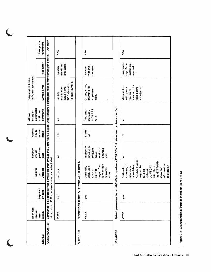
Overview of PannUb Members: Figure 2-2 lists all the parmlib members that are valid in MVS_ The table briefly describes the purpose of each member, indicates whether the member was introduced in MVT, VS2 Release 1, or MVS, and lists additional categories of information for each of the parmlib members_
26 OS/VS2 System Programming Ubrary: Initialization and Tuning Guide (VS2 Release 3.7)
r r Allows Response to Errors
I When was Directly Read at listing of IN/A=not applicable) member Required affects IPL or parameters intra- Supplied or perform- at com- at IPL or 'Unsupported I
Member duced? by IBM Optional ance mand command Syntax Error Read Error Parameters
COMMNDOO (xx) Commands to be issued by the control program immediately after Initialization. Also contains a parameter that controls prompting during TOO clock I
initialization. JES2 commands may not be included.
VS2-2 no OPtional no IPL no
GTFPARM Parameters to control GTF when GTF is started.
VS2-2 yes OPtionally Indirectly START Yes, auto-used. Built since SRM GTF matically automa- sysevent at START icallyat trace GTF. sysgen. Can option is be modified a tuning by install- aid. ation.
IEAABDOO Default parameters for an ABEND dump when a SYSABEND dd statement has been specified.
"1:1 ;. t-.)
If.>
I i. ~ g. ::t I
~
VS2-2 yes Optional. However, if member is unavailable, ABEND dumps may not be possible without DUMPOPT lists. (Also, see GTFPARM above for information on sysgen.)
~. Figure 2-2. Characteristics of Parmlib Members (part 1 of 8)
t-.) --.j
no IPL no
Ignores No com· N/A invalid com- mands are mand name. processed. TOO defaults to NOPROMPT.
On any error, Same as N/A prompts for with syn-all param- tax error. eters.
Message lists Error mes- N/A valid parms sage. Para-that were meters are accepted. I n- rejected. valid parms are rejected.
I
r
!It
o se ~ N
~ '" ~
l a 9 ~.
~
f a ~ .., ct, g
~ =' = ~.
~ ~ '< v.l N
'" i-~ .... ~
Allows Response to Errors When was Directly Read at listing of (N/A=not applicable) member Required affects IPL or parameters
intro- Supplied or perform- at com- at IPL or Unsupported
Member duced? by IBM Optional ance mand command Syntax Error Read Error Parameters
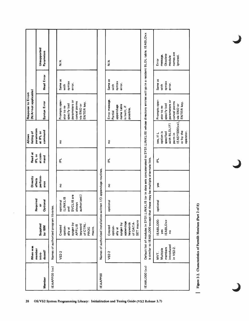
IEAAPFOO (xx) Names of authorized program libraries.
VS2-2 Created optional no IPL no Prompts oper- Same as N/A option- (LlNKLIB ator to re- with ally at and specify bad syntax sysgen by SVCLlB are parameters or error. APFLIB always cancel parms keyword authorized.) via END or
ofCTRL- ENTER key. PROG macro.
IEAAPPOO Names of authorized installation-written I/O appendage routines.
VS2-2 Created optional no IPL no Error message. Same as N/A option- Partial with ally at appendage syntax
sysgen by name table error. appendage is built, if keywords possible. of DATA-SET macro
IEABLDOO (xx) Default list of modules in SYS1.LlNKLI B (or in data sets concatenated to SYS1.LlN KLlB) whose directory entries will go in a resident BLDL table. IEABLDxx
is similar to IEABLDOO except that these may be multiple alternate lists.
MVT. IEABLDOO- optional yes IPL yes, if L Prompts oper- Same as Error
Multiple yes option is ator to re- with message.
members IEABLDxx- specified specify bad syntax Obsolete introduced no with BLDL(F) parameters or error. module in VS2-2. parm in cancel parms names are
IEASYSOO(xx), via END or ignored. or by the ENTER key. operator.
Figure 2-2. Characteristics of Pannlib Members (part 2 of 8)
~. ~ \."

r ("
Allows Response to Errors When was Directly Read at listing of (N/A=not applicable) member Required affects IPL or parameters intro- Supplied or perform- at com- at IPL or
Member duced? by IBM Optional ance mand command Syntax Error Read Error
IEADMPOO Default parameters for an ABEND dump when a SYSUDUMP dd statement has been specified.
VS2-2 yes Optional. no IPL no Message Ii sts Error However, if valid parms message. member is that were Parms are unavailable, accepted. rejected. ABEND dumps Invalid parms may not be are rejected. possible without DUMPOPT lists. Built automatic-
- ally at sysgen. Can be modified by instal-lation.
IEAFIXOO (xx) Names of modules from SYS1.LPAlIB, SYS1.SVClIB, and SYS1.lIN KliB to be fixed in real storage for the life of the IPL.
"" I!l ... N
t/}
'< '" i ;'
[
VS2-1 IEAFIXOO- IEAFIXOO is yes created
IEAFIXxx- optionally no at sysgen
[ Figure 2-2. Characteristics of Pannlib MembelS (part 3 of 8) o· = I
f ~
yes IPL yes, if L Prompts oper- Same as oPtion is ator to re- with spec'd with specify bad syntax FIX parm in parameters or error. IEASYSOO(xx), cancel them or by the via END or operator. ENTER key.
("
Unsupported Parameters
N/A
Error I message.
Obsolete module names are ignored.
I
I
I
'" o
o ~ ~ N ~ '< ~ .. :3
{ :3 S·
IJQ
~ ~ -e. =-. i-'" g' ~ ~
~ e. ~ ~ a: .. ~ N
::0
~ ~ .., ~
Allows Response to Errors When was Directly Read at listing of (N/A=not applicable 1 member Required affects IPlor parameters intro- Supplied or perform- at com- at IPl or Unsupported
Member duced? by IBM Optional ance mand command Syntax Error Read Error Parameters
IEAIGEOO Resident ERP list in MVT. (Not supported in VS2 Release 2.1
IEAIGGOO Resident access method list. (Not supported in VS2 Release 2.)
IEAIPSOO (xx) Parameters of an installation performance specification that control Workload Manager of System Resou'rce Manager.
VS2-2 IEAIPSOO- IEAIPSOO= yes both IPL yes, if L Prompts oper- Prompts N/A yes req'd and SET option is ator to re- operator to
IEAIPSxx- lEAl PSxx=opt. IPS spec'd with specify al- respecify no command. IPS parm in temate IPS IPS=xx or to
IEASYSOO(xx), member orto cancel parm or by the default to via END or operator. IEAIPSOO. If no ENTER key.
IEAIPSOO, uses coded defaults.
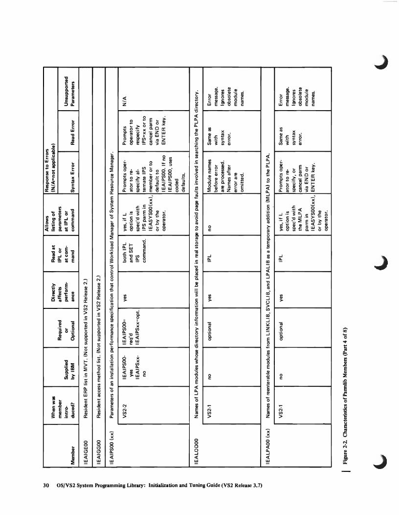
IEALODOO Names of LPA modules whose directory information will be placed in real storage to avoid page faults involved in searching the PLPA directory.
VS2-1 no optional yes IPL no Module names Same as Error before error with message . are processed. syntax Ignores Names after error. obsolete error are module omitted, names.
IEALPAOO (xx) Names of reenterable modules from LIN KLI B, SVCLI B, and LPALI B as a temporary addition (MLPAI to the PLPA.
VS2-1 no optional yes IPL yes, if L Prompts oper- Same as Error option is ator to re- with message. spec'd with specify, or syntax Ignores the MLPA cancel parm error. obsolete parm in via END or module I EASYSOO(xx), ENTER key. names. or by the operator.
- - - ------- -- - -- -
Figure 2-2. Characteristics ofParmlib Members (part 4 of 8)
'-' ~ '-'

~
$. N
I;Il '<
~ = ~ g. = I o ~ ~ .
.... -
(' ('
Allows Response to Errors When was Directly Read at listing of (N/A=not applicable) member Required affects IPL or parameters intro- Supplied or perform· at com· at IPL or
Member duced? by IBM Optional ance mand command Syntax Error Read Error
IEAOPTOO (xx) Parameters that control resource management algorithms in the System Resource Manager.
VS2·2 no optional yes IPL yes, if L Error Prompts
Note 1 option is message. operator to spec'd with Default select the OPT values sub· altemate parm in stituted. member by I EASYSOO(xxl. respecify or by the ing OPT operator. parm.
IEAPAKOO "Pack List" names of groups of modules in LPALIB that NIP will load between page boundaries to minimize page faults.
VS2·1 yes. Is optional yes IPL no automatic· ally copied at sysgen. Can be modified by instal· lation.
IEARSVOO Resident SVC list in MVT. (Not supported in VS2 Release 2.)
I Note 1: IEAOPTOO is a required specification; it is not a default in the usual sense. The SRM depends on this specification for its control of the resource management algorithms.
I Figure 2·2. Characteristics of Parmlib Members (part 5 of 8)
Bypasses the The pack pack group groups read that contains before the the error. error are P rocesses the processed. next pack Other pack group. groups are
omitted.
('
Unsupported Parameters
N/A
Error message. Ignores obsolete module names.
t..> N
o Ul
~ N
~ '" !t :3
{ :3 ~.
~ ~ -~ Fr-.. !:t. g
8-~ e. ~ ~ ~ ~ N
:;= '" ;;-
~ t..>
~
Allows Response to Errors When was Directly Read at listing of (N/A=not applicable) member Required affects IPL or parameters intro· Supplied or perform· at com· at IPL or Unsupported
Member duced? by IBM Optional ance mand command Syntax Error Read Error Parameters
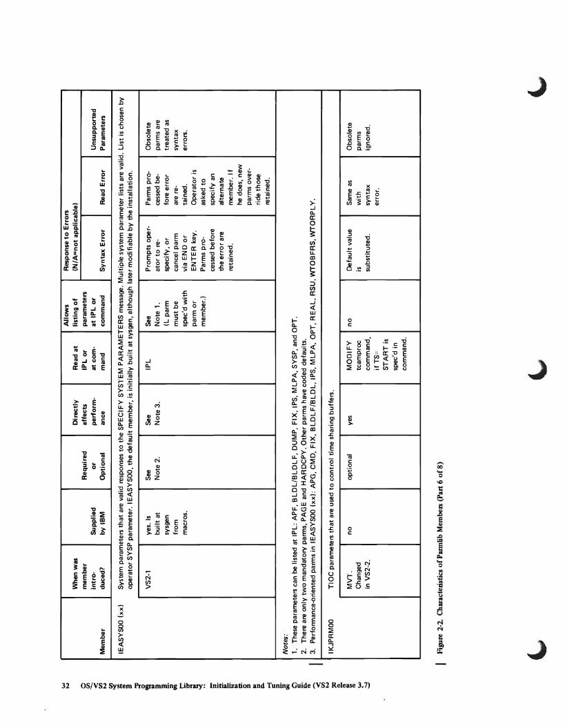
IEASYSOO (xx) System parameters that are valid responses to the SPECIFY SYSTEM PARAMETERS message. Multiple system parameter lists are valid. List is chosen by operator SYSP parameter. IEASYSOO, the default member, is initially built at sysgen, although later modifiable by the installation.
VS2·1 yes. Is See See IPl See Prompts ope r· Parms pro· Obsolete built at Note 2. Note 3. Note 1. ator to re- cessed be· parms are sysgen (l parm specify, or fore error treated as from must be cancel parm are reo syntax macros. spec'd with via END or tained. errors.
parm or ENTER key. Operator is member.) Parms pro· asked to
cessed before specify an the error are alternate retained. member. If
he does, new parms over· ride those retained.
Notes: 1. These parameters can be listed at IPl: APF, BlDl/BlDlF, DUMP, FIX, IPS, MlPA, SYSP, and OPT. 2. There are only two mandatory parms, PAGE and HARDCPY. Other parms have coded defaults. 3. Performance-oriented parms in IEASYSOO (xx): APG, CMD, FIX, BlDLF/BlDl, IPS, MlPA, OPT, REAL, RSU, WTOBFRS, WTORPlY.
IKJPRMOO TIOC parameters that are used to control time sharing buffers.
MVT. no optional yes MODIFY no Default value Same as Obsolete Changed tcamproc is with parms in VS2·2. command, substituted. syntax ignored.
ifTS= error. START is spec'd in command.
Figure 2·2. Characteristics of Pannlib Members (part 6 of 8)
'-' '-' \.,

,... ("
Allows Response to Errors When was Directly Read at listing of (N/A=not applicable' member Required affects IPL or parameters intra- Supplied or perform- at com- at IPL or Unsupported
Member duced? by IBM Optional ance mand command Syntax Error Read Error Parameters
IRBMF100 (xx, Parameters to control M F/1 data and reports_
VS2-2 IRBMF100- IRBMF100= Indirectly START Yes, if Error message Error msg_, N/A yes req'd since MF/1 MF1 OPTION All accepted and handles
IRBMF1xx- to run MF/1 is a tun- command_ parm is parms are same as with no IRBMF1xx= ing aid_ spec'd_ listed_ The syntax error.
opt. operator is prompted to correct in-valid parms.
LNKLSTOO (xx, List of data sets to be concatenated to SYS1.LI NKLIB. LNKLSTxx is similar to LNKLSTOO except that these may be multiple alternate lists.
."
~ 1>.1
!;I:l
'< '" ~ 2. ~ g. =
MVIKEYOO
MVT no optional Multiple members in VS2-2_
Parameters to control MSSC data and messages_
VS2-3 yes_ Is requ ired for automatically MSS copied at sysgen. Can be modified by installation.
I Figure 2-2. Chamcteristics of Pannlib Members (part 7 of 8) o S ~ . ... ...
no IPL Yes, if L option is spec'd with LNK parm in I EASYSOO(xx', or by the operator.
yes IPL Yes, at IPL. If error occurs, default is taken.
Prompts oper- No data Error msg. ator to re- sets are Data sets specify, or concaten- not found cancel parm ated with will not be via END or LlNKLIB. concaten-ENTER key. Operator ated with
can re-IPL LlNKLIB. to specify altemate LNKLST member.
Prompts oper- Same as Same as ator to enter with with parm or syntax syntax re-IPL. error. error.
("

~
o o:tl
~ t-.I o:tl '< It a
f §.
OQ
t""
I -~ If I»
g' I» :; Q.
i. OQ
i '< o:tl t-.I
~
~ ~ \H
~
Allows Response to Errors When was Directly Read at listing of (N/A=not applicable) member Required affects IPL or parameters intro- Supplied or perform. at com· at IPL or Unsupported
Member duced? by IBM Optional ance mand command Syntax Error Read Error Parameters
PARMTZ Time zone constant: the value by which local time differs from Greenwich Mean Time.
VS2-1 no optional no IPL no Uses sysgen Same as N/A value. If no with value was syntax spec'd at error. sysgen, default of o is used.
SMFPRMOO (xx) Parameters that define SMF oPtions. Multiple members replace SMFDEFL T, which was used in MVT and VS2 Release 1.
MVT. PRMOO PRMOO= Indirectly IPL Yes, if OPI Prompts oper· Same as Same as Changed yes req'd. since SMF parm is ator to enter with with in VS2-2. PRMxx PRMxx=oPt. can supple· spec'd as parm or syntax syntax
no (See ment MF/l YES re-IPL. error error. Note 4.1 asa
tuning aid.
VA TLSTOO (xx) Volume attribute list that defines the "mount" and "use" attributes of di reet access volumes. Mu Itiple I ists named V A TLSTxx replace PR ESR ES.
MVT. no optional yes IPL No. Operator Error msg. Operator is Old member Name and has option By·passes given (PRESRES) format to get list bad entry. choice of can't be changed only if error Processes processing processed. in VS2-2. occurs. remaining remaining
entries. list(s) if multiple lists, or specifying new VATLST VATLSTxx member, or re·IPLing.
Note 4: The installation must add DSV=2 or DSV=3 to the SMF default list SMFPRMOO so that the I EHUCAT util ity will be able to update MVT catalogs.
Figure 2-2. Characteristics of Purnlib Members (part 8 of 8)
'-' '-' \..,

How to Control Parmlib: To control parmlib and assure that it is managable, you should consider the following problem areas and suggested solutions:
• Delete unsupported parameters and members. Since most components treat unsupported parameters from previous releases as syntax errors, you should probably remove the old parameters or build parmlib from scratch. This action will minimize the need for operator responses during an IPL. Furthermore, you can save space by removing unsupported members. Figure 2-2 shows which old members are not supported in MVS, and which changed members can involve unsupported parameters.
• Update parrnlib with new and replacement members, as you gain familiarity with the new release. You can use the IEBUPDTE utility to add or replace members. Figure 2-3 illustrates the JCL for adding three new members and replacing two old members: IEABLDOO, IEALODOO, lEAP AKOO, IEASYS05, and IEASYS06. (Consult the OS/VS Utilities manual for further information on the use of IEBUPDTE.) To prevent excessive growth of parmlib, use the "compress' function of IEBCOPY to delete obselete data.
/lADDLISTS /lSTEP /lSYSPRINT /lSYSUTl /lSYSUT2 /lSYSIN
JOB 61938, 'R.L. WILSON' EXEC PGM=IEBUPDTE, PARM=MOD DD SYSOUT=A DD DSNAME=SYS1.PARMLlB, DISP=OLD DD DSNAME=SYS1.PARMLlB,DISP=OLD DO DATA
.I
.I SYS1.LlNKLIB
.I
.I
.I
./
.I
.I
.I
.I
.I
'*
ADD NAME=IEABLDOO, LlST=ALL NUMBER NEW1=01,INCR=02 IEFSD061,IEFSD062,IEFSD064,IEFSD104, IEFVM1, IEFWCOOO,IEFWDOOO, IEFW21SD, IEFW41SD, IEFW42SD, IEFXJOOO REPL NAME=IEALODOO, LEVEL=Ol, SOURCE=l, LlST=ALL NUMBER NEW1=10,INCR=100 IEFAB400, IGG0325A, IGG0325H,IGC0003B, IGG0325B, IGG0325D, IGG0325E, IGG0325G, IFG0202J, IFG0202K, IFG0202L REPL NAME=IEAPAKOO, LEVEL=Ol, SOURCE=l, LlST=ALL NUMBER NEW1=01,INCR=02 (lEFAB400, IGG0325A, IGG0325H, IGC0003BI, (lGG0325B, IGG0325D, IGG0325E, I GG0235GI, (I FG0202J, I FG0202K, I FG0202 LI ADD NAME=IEASYS05, LlST=ALL NUMBER NEW1=01,INCR=02 MLPA=(OO, 01 I, BLDL=OO, SQA=2 ADD NAME=IEASYS06, LlST=ALL NUMBER NEW=Ol, INCR=02 MLPA=(02, 031, BLDLF=(OO, 01 I, SQA=l, FIX=(OO,Oll,OPI=NO ENDUP
Note: This example shows the format of I EBUPDTE statements, not the content of parrnlib members.
Figure 2-3. Example of Adding and Replacing Parmlib Members by Means of the IEBUPDTE Utility
Part 2: System Initialization - Overview 35

• Keep track of which parameters were specified at sysgen (through CTRLPROG and DATASET macros) and which parameters are included in particular parmlib members. This bookkeeping is necessary for two reasons: 1. The system doesn't keep track of parmlib members and their parameters. 2. The default general parameter list lEASYSOO is always read by NIP and Master Scheduler Initialization. The list's parameters can be overridden by the same parameters when they are specified in alternate general lists, such as lEASYSOl, lEASYS02, etc. Furthermore, certain parameters, such as FIX, APF, and MLPA, direct the system to particular specialized members (in this example, lEAFIXxx, IEAAPFxx, and lEALPAxx). The installation should keep records of which parameters and which values are in particular members, and which general members point to which particular specialized members (COMMNDxx, lEALPAxx, etc.) A grid or matrix for such bookkeeping is very helpful.
• Allocate sufficient space for parmlib. The space must be a single extent. One way to estimate space is to count the number of characters, including blanks, (by counting 80-character records) in all members. Then add a suitable growth factor (e.g., 100-300%) to allow for future growth of alternate members. Consult Figure 2-2 to determine which members can have multiple alternates. To recapture space from obselete members, use the "compress" function of IEBCOPY.
Note: It is better not to let members cross cylinder boundaries because some members are used during IPL. Those that are will generate I/O errors during IPL if they cross cylinder boundaries.
• Decide the volume and device that should hold parrnlib. The volume could be demountable, although it must be mounted in order for the operator to start GTF, to start MF /1 as supplied with the system, to start time sharing by use '\ of the MODIFY tcamproc command, or to try to specify a new installation ..., performance specification by use of the SET IPS command. The volume must be cataloged, unless it is SYSRES. It could be placed on a slow or moderate speed device.
• Password protect the data set. Parrnlib should be password protected for "write". The purpose is to shield the appendage member (IEAAPPOO) and the Authorized Program Facility member (lEAAPFxx) from user tampering. Member IEAAPPOO is particularly sensitive, since a user could add an appendage that would give his routine control in zero protection key and supervisor state.
General Syntax Rules for the Creation of Members: The following general syntax rules apply to the creation of most parmlib members. Exception to these rules are described under specific members later in this chapter. The general rules are:
• Record size is 80 bytes. • Any columns between 1 and 71 may contain data. • Columns 72 and 80 are ignored. • Continuation is indicated by a comma followed by one or more blanks after
the last entry on a record. • Leading blanks are suppressed. A record therefore need not start at a particular
column. • Suffix member identifiers (such as LNK=A2) can be any alphameriC
combination.
36 OSjVS2 System Programming Library: Initialization and Tuning Guide (VS2 Release 3.7)

Causing an Alternate Nucleus Substitution
Another less common way to change the system at an IPL is to cause the IPL program to read a member of a nucleus data set that is different from IEANUCOl, the default nucleus member. One reason for such a nucleus switch may be the need to apply a PTF. The operator process to cause the switch is described under "Loading a Secondary Nucleus" in the Operator's Library: OS/VS2 Reference (JES2).
System Tailoring Through Operator Commands
After IPL, several operator commands provide additional system tailoring by directing particular groups of parameters to specific system components. The commands consist of:
• START tcamproc • MODIFY tcamproc • SET IPS • STARTGTF • START MFI • START vtamproc
Starting TCAM
The operator can enter TCAM initialization parameters when he starts TCAM, as a response to the SPECIFY TCAM PARAMETERS message. TCAM issues the message if the system programmer accidentally or deliberately omitted one or more required parameters when he coded the INTRO macro for TCAM assembly. In response to the message, the operator can add to or modify existing TCAM parameters. (For information on the TCAM parameters, refer toOS/VS2 reAM Programmers Guide.)
Starting VT AM
VTAM start options can be entered by the network operator as parameters in the ST ART command or they can be specified in a start option list. The start option list is stored in SYS l.YT AMLST and is specified by the LIST parameter in the START command. For information about VTAM initialization, refer to OS/VS2 System Programming Library." VT AM.
Part 2: System Initialization - Overview 37

Starting Time Sharing
The operator starts TCAM, then issues the following command in MVS in order to ..J start time sharing:
MODI FY tcamproc, TS=ST ART [,membernamel
The optional parameter membername can specify an installation-defined parmlib member, or can default to the parmlib member IKJPRMOO. In either case, the member is ready by the Terminal I/O Coordinator (TIOC). The TIOC uses the parameters mainly to control time-sharing buffers. (For additional information on TIOC parameters, see the description of member IKJPRMOO later in this chapter.)
Using SET IPS to Change Workload Manager Parameters
The SET IPS command causes the Workload Management routine of the System Resources Manager to receive a specific installation performance specification (IPS). This IPS is a parmlib member (IEAIPSxx). By use of this command, the installation can dynamically change IPS parameters between IPLs. (For further information, refer to the IPS parameter in the description of the IEASYSxx member, and in the chapter entitled "How to Use the System Resources Manager".)
38 OSjVS2 System Programming Library: Initialization and Tuning Guide (VS2 Release 3.7)

L
Starting GTF
When the operator starts the Generalized Trace Facility (GTF), the parameters are obtained from the PARM field of the START command and from a parmlib member. If the operator issues START GTF, the IBM-supplied cataloged procedure (named GTF) is read. The PROC statement of that procedure names GTFPARM as the member from which GTF will get its parameters. If, however, the installation wants to substitute another member in place of GTFPARM, the operator may enter the alternate member name with the MEMBER keyword of the START command. (For further information on GTF initialization parameters, see the description of member GTFPARM later in this chapter. For other information on starting or using GTF, refer to the GTF chapter in OS/VS2 System Programming Library: Service Aids.)
Starting MF /1
The System Activities Measurement Facility (MF/I) is started by means of the ST ART procname command. Parameters to control measurements, reports, and SMF records are taken from a merge of three sources, in this order:
1. PARM field of the START command 2. PARM field of the EXEC statement in the proc named by the command 3. MF / I partitioned data set member (typically the IRBMFIxx member of parmlib)
If the IBM-supplied procedure (named MF I) is specified in the command, the MF/I partitioned data set is SYSI.PARMLIB. The MF/1 member names must always be of the form IRBMFIxx. The default member IRBMFlOO is supplied by IBM. (For further information on MF/I, its uses and parameters, see the part of this book entitled "How to Use the System Activity Measurement Facility (MF/I.")
Implicit System Parameters
Various system requirements, although not involving explicit parameters, affect the way the system performs. These system requirements may be considered as "implicit" parameters. They involve dd statements, data sets, hardware choices, etc. Some examples are:
• SYSABEND and SYSUDUMP dd statements. Without these statements, the parameters in parmlib members IEAABDOO and IEADMPOO and the dump option lists in ABEND macro instructions are useless, since an ABEND dump cannot be taken.
• SYSMANX and SYSMANY data sets must be allocated on direct access volumes and be cataloged. If this condition is not met, the Master Scheduler fails during IPL. This may be considered an implicit SMF parameter.
• Addition of new modules to SYS1.LPALIB through use of IEBCOPY or the Linkage Editor. This affects the size and usefulness of the LPA that is loaded by specification of the CLP A parameter at IPL.
• Choice of the device on which the LPA paging data sets will reside. This choice affects the speed at which LPA modules can be paged into real storage and thus system performance.
Part 2: System Initialization - Overview 39

• Definition of page data sets by means of the DEFINE SPACE command. The PAGE parameter, issued at IPL through parmlib and/or the operator, is meaningful only if the specified data sets have been previously formatted by the DEFINE SPACE command. (See OS/VS2 Access Method Services for information on this command.)
Warning: NIP enforces a uniprocessor IPL when a system that has been generated without MP modules tries to initialize on MP or half duplex. The operator at IPL must ensure that at least 768K bytes of contiguous storage are dialed online, if the system was generated with ACRCODE=NO in the CTRLPROG macro. If the storage requirement is not met, NIP issues a message and may cause a wait state.
40 OSjVS2 System Programming Library: Initialization and Tuning Guide (VS2 Release 3.7)

Descriptions of Individual PARMLIB Members
The individual parmlib members, listed in alphabetic order, are described in the following topics.
Member Name: COMMNDxx
Status: New for VS2 Release 2
Use of the Member
COMMNDxx is an optional installation-created list of automatic commands to be internally issued by the system as part of Master Scheduler Initialization. COMMNDxx is useful for automatic entry of commands, such as START MF/l, that may be frequently issued at System Initialization. The member cannot be used to issue JES2 commands, since COMMNDxx commands are issued before JES2 is started. COMMNDxx also contains the TOD keyword. This keyword indicates whether messages from TOD Clock Initialization should be issued to prompt the operator. The installation can use this keyword to speed up the initialization process, if it feels that these messages are unnecessary. (See the NOPROMPT operand of the TOD keyword.)
The TRACE ON command may be placed in a COMMNDxx member, if OS Trace is desired after NIP processing (to cover log initialization, startup of GTF, and the latter part of JES2 initialization). OS Trace is turned off during GTF operation if TRACE ON was requested at IPL. TRACE OFF may be requested at the next IPL by operator command (before responding to the JES2 SPECIFY OPTIONS message), or via another COMMNDxx member.
Caution: The use of TRACE ON should not be encouraged, because it degrades the system and because it can't be stopped until the next IPL.
The following commands should not be put in COMMNDxx because they are console·oriented. They should be issued only on the console for which they apply:
Command
CONTROL MSGRT TRACK STOPTR
Abbreviation
K MR TR PT
Warning: Do not place JES2 commands in COMMNDxx, since JES2 is not started until after the COMMNDxx entries have been processed.
The default member COMMNDOO, if it exists, is read if CMD=xx is not included in the system parameter list (IEASYSxx) or is not specified by the operator. If Initialization can't find either the specified COMMNDxx member or COMMNDOO, processing continues without provision for automatic commands.
Part 2: System Initialization - PARMLIB Members 41

COMMNDxx (continued)
Parameter in IEASYSxx: (or issued by the operator) CMD = { aa }
(aa,bb ... )
The two-character identifier (aa, bb, etc.) is appended to COMMND to identify the COMMNDxx member(s) of parmlib. Multiple members can be specified.
Note: Commands issued from COMMNDxx do not show on the console. Therefore, the results of these commands appear on the console without the operator's seeing the command.
Syntax Rules
The following rules apply to the creation of COMMNDxx by means of the IEBUPDTE utility:
• Enter only one command per card image. Enter the COM= keyword, followed by the command enclosed in apostrophes. For example, to start TCAM through use of the IBM-supplied PROC, enter COM='s TCAM'.
• Specify the TOD=keyword on a single card image. For example, TOD= PROMPT (This entry will cause prompting messages during TOD clock initialization.)
• Do not specify continuation on any card image.
IBM-Supplied Defaults: None
Internal Parameters
Parameter
COM='command name'
{PROMPT }
TOD= NOPROMPT
Meaning
The specified command will be issued by the system during Master Scheduler Initialization.
Messages will (will not) be issued to the operator during TOD clock initialization
If NOPROMPT is specified, the system will prompt the operator to set the TOD clock only if the clock is not set, or in a multiprocessing system, if the TOD clocks are not synchronized.
42 OS/VS2 System Programming Library: Initialization and Tuning Guide (VS2 Release 3.7)
Default Value
No commands will be issued.
NOPROMPT

Member Name: GTFPARM (or an installation-supplied name)
Status: New for VS2 Release 2
Use of the Member
GTFPARM provides default or installation-defined trace options to control the Generalized Trace Facility (GTF). The member is read only when the operator (or an automatic command) issues START GTF. It is not used during System Initialization. (For use of the TRACE command to continue or discontinue OS Trace after IPL, see Operator's Library: VS2 Reference (JES2).)
The procnaine of the START command can name an IBM-supplied cataloged procedure. The PROC statement of that procedure identifies GTFPARM as the member from which GTF will get its trace parameters. If the installation wants to substitute another member in place of GTFPARM, the operator may enter the replacement member name on the START command with the MEMBER keyword.
The IBM procedure, as supplied in SYSl.PROCLIB, contains these statements:
IIGTF PROC IIIEFPROC EXEC
IIIEFRDER DO II IISYSLIB DO
MEMBER=GTFPARM PGM=AHLGTF,PARM='MODE=EXT,DEBUG=NO, TIME=NO' DSNAME=SYS1.TRACE,UNIT=SYSDA, SPACE=(4095,20),DISP=(NEW,KEEP) DSN=SYS1.PARMLI B(&MEMBERl,DISP=SHR
For further analysis of this procedure, refer to the GTF chapter of OS/VS2 System Programming Library: Service Aids.
Since default options in GTFPARM specify minimal data for only a limited number of traced events, you may wish to expand GTF'capabilities through one of the following methods:
• Specify another member name via the MEMBER keyword on the START command.
• Change the trace options in GTFPARM, by using the IEBUPDTE utility.
• Change the SYSLIB DD statement of the IBM procedure, in order to specify a different option list, which you create via IEBUPDTE.
• Retain the IBM procedure to handle default options, and write one or more alternate procedures, each specifying a different alternate parmlib member. You could design each member to contain GTF options useful under particular circumstances. Instruct the operator when to issue the START command for each procname.
GTF tries to read parameters from the specified parmlib member. If an error occurs in opening or reading the member, or if GTF detects a syntax error, it writes a diagnostic message to the operator, and requests him to SPECIFY TRACE OPTIONS, as if no GTF parrnlib member were available. The oper::.tor therefore must have a complete list of desired GTF parameters available when he starts the facility.
Part 2: System Initialization - PARMUB Members 43

GTFPARM (continued)
Parameter in IEASYSxx: None (or issued by the operator)
Syntax Rules:
The following rules apply to the creation of a GTF parrnlib member by means of the IEBUPDTE utility:
• Specify the TRACE keyword and its main options only on the first record. Do not place them on subsequent records. For example,
Record #1: TRACE=IOP,SVCP,SIO
This example requests the tracing of specific I/O interrupts, specific SVC interrupts, and all Start I/O operations.
• The second and subsequent records should contain only "prompting" keywords, such as 10= or SVC=. These keywords provide for detailed operands that indicate which I/O interrupts or which SVC interrupts should be traced. For example, the lOP and SVCP keywords in the Record # 1 example (above) must be followed by prompting records that name specific unit addresses and specific SVC numbers for which interrupts should be traced. As an example,
Record # 2: 10=(191,192, 193),SVC=(1 ,2,3)
If the specific operands of any prompting keyword are missing, GTF does not prompt the operator initially. It accepts a general specification. For example, if lOP is specified in record # 1, and particular device addresses are not specified in a later record, GTF assumes that tracing of I/O interrupts is desired for all devices.
Later, when all records have been read, GTF issues message AHL1031 TRACE OPTIONS SELECTED - 10 (rather than 10=(191,192,193)). The operator can then respond to the accompanying message AHL125A RESPECIFY TRACE OPTIONS OR REPLY U by entering Rxx,10=(I91 ,192, 193) to indicate the devices whose I/O interruptions should be traced_
• An END statement or an end-of-file must follow all prompting keywords.
• If you need to specify additional operands for the same keyword, restate the keyword and the additional operands in a subsequent prompting record. The previous examples, expanded to include additional SVC numbers and an END keyword, would appear like this:
Record # 1:
Record # 2:
Record # 3:
TRACE=IOP,SVCP,SIO
10=(191,192, 193),SVC=(1 ,2,3)
SVC=(4,5,6,7,8,9,10),END
44 OSjVS2 System Programming Library: Initialization and Tuning Guide (VS2 Release 3.7)

GTFPARM (continued)
• Certain trace options (prompting vs. non-prompting, general vs. specific) are mutually exclusive. (See Figure 2-4) Options listed in the same column of the table are mutually exclusive. If you select two or more options from the same column, the option listed highest in the column will take effect. For example, if you specify both SYSP and SIO from the first column, SYSP will take effect and SIO will be ignored.
Note: Options listed in each column are mutually exclusive. Preferential order is from top to bottom.
SYSM SYSM SYSM SYSM SYSM SYSM DSP USR TRC PCI SRM SYSP SYSP SYSP SYSP SYSP SYSP "- /
V SYS SYS SYS SYS SYS SYS These parameters are not mutually SlOP lOP SVCP PIP EXT RR exclusive with other parameters. SIO 10 SVC PI
Figure 2-4. Mutually Exclusive Options for GTFPARM
IBM-Supplied Defaults
When GTF is started by specifying the IBM-supplied cataloged prccedure, the following options exist in GTFPARM:
TRACE=SYSM,USR,TRC,DSP,PCI,SRM
These keywords will cause the following events to be recorded: SVC interruptions, I/O interruptions, PCI interruptions, program interruptions, external interruptions, dispatcher executions, Start I/O instructions, entries to the System Resource Manager, entries to recovery routines, events associated with GTF (TRC), and data passed to GTF via the GTRACE macro (USR). All keywords except USR result in minimal format trace entries. USR entries will be the length specified by the user in the GTRACE macro. Such entries may optionally be a maximum of 256 bytes, excluding the prefix.
Internal Parameters
Parameter
SYS
SYSP
Meaning and Use
This parameter requests comprehensive recording for six system events: I/O, SIO, SVC, program, external interruptions, and entry to recovery routines (RR). If any additional trace options are coded (e.g., SRM, DSP), trace entries for these options will also be comprehensive.
This parameter produces results similar to that produced by SYS, except that GTF prompts for particular events (e.g., address of I/O device or SVC number). As with SYS, if any additional trace options are coded, trace entries for these options will also be comprehensive.
Part 2: System Initialization - PARMLIB Members 4S

GTFPARM (continued)
Parameter
SYSM
SIO
SlOP
10
lOP
SVC
SVCP
PI
PIP
EXT
Meaning and Use
This parameter produces results similar to that for SYS, except that minimal trace data are recorded for the six events. If any additional trace options are coded (e.g., SRM, DSP), trace entries for these options will also be minimal, except for USR entries. USR entries are the length specified by the user in the GTRACE macro.
NOTE: Specification of either SYS or SYSM causes the following trace options to be ignored if specified, since they are included in SYS or SYSM: SIO, 10, SVC, PI, EXT,RR.
This parameter requests comprehensive recording for system SIO operations.
This parameter is similar to SIO except that it requests GTF to prompt for the addresses of specific devices (e.g., 151, 152) for which SIO events should be recorded. Only the devices for which the operator replies, or the parmlib member specifies, will cause SIO entries in the trace.
This parameter requests comprehensive recording of all nonPCI I/O interruptions. To obtain recording ofPCI interruptions, specify PCI. Both options may be specified.
This parameter requests the same type of recording as does 10, except that GTF prompts for the addresses of specific devices whose I/O interruptions will be recorded.
This parameter requests comprehensive recording of all SVC interruptions.
This parameter is similar to SVC, except that GTF will prompt for specific SVC numbers for which data is to be recorded.
This parameter requests comprehensive recording for all program interruptions (1-19).
This parameter is similar to PI except that GTF prompts for the specific interruption codes for which data is to be recorded.
This parameter requests comprehensive recording for all external interruptions.
46 OS/VS2 System Programming Library: Initialization and Tuning Guide (VS2 Release 3.7)

GTFPARM (continued)
Parameter
RR
DSP
PCI
SRM
TRC
USR
END
Meaning and Use
This parameter requests that uses of recovery routines (FRRs and STAE/ESTAE routines) be recorded. The trace record is created when the recovery routine returns control to the Recovery Termination Manager (RTM). Data is in comprehensive format except when the option is specified via SYSM.
This parameter requests recording for the local dispatching of units of work (service request block (SRB) and TCB). The option is not included in the specification of SYS or SYSM. It must be specified in addition to other parameters. The parameter produces comprehensive format except when SYSM is also specified. With SYSM, data is in minimal format.
This parameter requests that PCI interruptions be recorded in the same format as other requested I/O trace records. If specific I/O device addresses are speCified through prompting records, the PCI interruptions will be recorded for the same devices. I/O tracing must be requested, since PCI cannot be specified without 10.
This parameter requests a trace entry each time that the System Resource Manager (SRM) is invoked. The option is not included in the specification of SYS or SYSM. It must be specified in addition to other parameters. Data is in comprehensive format except when SYSM is also specified. Comprehensive format includes the jobname.
This parameter requests that traced events include those related to GTF processing itself. If this parameter is not specified, GTF-related events will be excluded from the trace output.
This parameter requests that user data passed to GTF via the GTRACE macro be recorded with the system data.
This parameter indicates the end of the prompting records. In the parmlib member an end of file serves the same pur· pose. Never include the END parameter in the first record (the record that contains the TRACE parameters), since GTF regards such occurrence as an error.
Part 2: System Initialization - PARMLIB Members 47

Member Name: IEAABDOO - (See also IEADMPOO)
Status: New for VS2 Release 2
Use of the Member
IEAABDOO contains IBM defaults and/or installation assigned parameters for ABDUMP, for use when an ABEND dump is written to a SYSABEND data set. (For ABDUMP parameters associated with a SYSUDUMP data set, see member IEADMPOO.)
ABDUMP parameters for a dump to be taken to a SYSABEND data set may be specified in any of three ways:
• A parameter list pointed to by the DUMPOPT keyword of an ABEND macro instruction. * The list can be built by using the list form of the SNAP macro. (See Supervisor Services and Macro Instruction for details regarding the ABEND and SNAP macros.)
• Default options specified in IEAABDOO. These options control the content of the ABEND dump if the programmer doesn't include the DUMPOPT keyword and its associated parameter list with his ABEND, CALLRTM, or SETRP macro. If the DUMPOPT keyword is included, the specified options are merged with those in IEAABDOO.
• Temporary override options that an operator can specify with a CHNGDUMP command (see cautionary statement below).
The reader should note that options specified by the CHNGDUMP command are distinctly different from those provided by the DUMPOPT list or the IEAABDOO options. Either of these lists can provide a reasonable dump, selected either by the application programmer or the installation system programmer. The CHNGDUMP command, however, must be issued very carefully, in order not to nullify dump options. Parameters in a CHNGDUMP command are overriding; that is, they temporarily replace all dump options specified in both IEAABDOO and all ABEND macro instructions. Only those parameters specified in CHNGDUMP are effective. Parameters not specified in CHNGDUMP are temporarily nullified, even though they still exist in IEAABDOO or in ABEND DUMPOPT lists. The overrides prevail until the operator issues another CHNGDUMP command, specifying the DEL keyword, or until the system is reinitialized (whichever occurs first).
As an example of how CHNGDUMP can accidentally wipe out desired ABDUMP options, assume that IEAABDOO contains the following options:
SDATA=(SOA,CB,ENO),PDAT A=(PSW,R EGS,SA,ALLPA)
Further assume that the operator is told to add TRT to the SDAT A options, in order to dump the trace table, and to add SPLS to the PDATA options in order to dump user storage acquired for the failing task. The operator, having only a superficial grasp of the command, enters:
CHNGDUMP SET,SYSABEND,SDATA=(TRT),PDATA=(SPLS)
* An ABEND dump can also be requested by a CALLRTM or SETRP macro. See OS/VS2 System Programming Library: Supervisor.
48 OS/VS2 System Programming library: Initialization and Tuning Guide (VS2 Release 3.7)

IEAABDOO (continued)
The operator thinks he has added the TRT and SPLS parameters to an incomplete list and that he has expanded the list by two parameters. Actually, the operator has set up effectively a new parameter list containing only two parameters: SDATA= TRT and PDATA=SPLS. He has unwittingly overridden and therefore nullified SDATA=(SQA,CB,ENQ),PDATA=(PSW,REGS,SA,ALLPA). He has also overridden any DUMPOPT parameters specified by programmers for use with their ABEND macro instructions. (For syntax information on the CHNGDUMP command refer to Operator's library: VS2 Reference (JES2).)
The ABDUMP Initialization routine reads IEAABDOO to get ABDUMP parameters. If during Initialization, IEAABDOO is found to be invalid or can't be located, the operator is notified_ No prompting occurs. If both valid and invalid options are included in the member, or a syntax error is encountered, a message lists the valid options that were accepted before the error occurred.
Parameter in IEASYSxx: None (or specified by the operator)
Syntax Rules
The following rules apply to the replacement of IEAABDOO by means of the IEBUPDTE utility:
• There are two keywords, SDATA and PDATA. Each keyword is followed by a string of operands separated by commas and enclosed in parentheses. A single operand does not need parentheses_
Examples:
SDATA=(SOA,CB,ENO,TRT) or SDATA=ALLSDATA
PDATA=(pSW,REGS,SA,ALLPA,SPLS) or PDATA=ALLPDATA
• Normally both parameters (i.e., SDATA=operands and PDATA=operands) can fit on one card image. If, however, continuation is needed, use a comma followed by a blank.
Example:
SDATA=(SOA,CB,ENO,TRT),
PDATA=(PSW,REGS,
SA,ALLPA,SPLS)
Part 2: System Initialization - PARMLIB Members 49

IEAABDOO (continued)
IBM-Supplied Defaults
The following defaults are placed in IEAABDOO by IBM:
SDATA=(LSOA,CB,ENQ,TRT),PDATA=(ALLPA,SPLS)
These options request a dump of the following areas:
• LSQA, including subpools 229 and 230 • formatted control blocks for the task • formatted enqueue control blocks for the task • GTF trace or supervisor incore trace
(See explanation under TRT parameter) • modules listed on the link pack area queue and the job pack area queue, and
active SVC modules related to the failing task • user storage allocated for the task
Internal Parameters
Parameter
SDATA=
ALLSDATA
Meaning and Use
All the following options are automatically specified.
The follOwing parameters request dump of specific SDATA areas, as indicated:
NUC
SQA
LSQA
SWA
CB
ENQ
TRT
Control program nucleus. SQA, LSQA and the PSA are included.
The system queue area.
Local system queue area for the address space, including sub pools 229 and 230.
Scheduler work area used for the failing task.
Control blocks related to the failing task.
Enqueue control blocks (QCBs and QELs) related to the failing task.
GTF or supervisor trace table depending on whether the ABEND occurs after or during IPL, and whether the TRACE ON command was issued at IPL. If the ABEND occurs during NIP or Master Scheduler Initialization, the supervisor trace is displayed. Otherwise, the GTF trace is displayed, provided that GTF has been started. If GTF is not running, and the TRACE ON command was issued at IPL, the Supervisor trace table is displayed. (For the use of the TRACE command, see Operator's Library: VS2 Reference (JES2).
50 OS!VS2 System Programming Library: Initialization and Tuning Guide (VS2 Release 3.7)

L
IEAABDOO (continued)
Parameter Meaning and Use
PDATA=
ALLPDATA All the following options are automatically specified.
The following parameters request dump of specific PDATA areas,
as indicated:
PSW
REGS
SA or SAH
JPA
LPA
ALLPA
SPLS
Program status word at entry at ABEND.
Contents of general registers at entry to ABEND.
SA requests save area linkage information and a backward trace of save areas. This option is automatically selected if ALLPDATA is specified.
SAH requests only save area linkage information.
Contents of the job pack area (module names and contents) that relate to the failing task.
Contents of the LP A (module names and contents) related to the failing task. Includes active SVCs related to the failing task.
Contents of both the job pack area and the LP A, as they relate to the failing task, plus SVCs related to the failing task.
User storage subpools (0-127) related to the falling task.
Part 2: System Initialization - PARMLIB Members 51

Member Name: IEAAPFxx
Status: New for VS2 Release 2
Use of the Member
IEAAPFxx is a list of program library names (dsnames) and corresponding volume serial numbers that require APF authorization. (APF means the Authorized Program Facility.) SYSI.LINKLIB and SYSI.SVCLIB are automatically authorized. SYSI. LPALIB, however, is not automatically authorized, since it is closed at the end of NIP processing and is not required until the next IPL at which time the LPA is to be reloaded.
If an installation wants IEAAPFxx, it must explicity create the member via the IEBUPDTE utility. The default member IEAAPFOO, however, may be optionally created at sysgen through the use of the APFLIB keyword of the CTRLPROG macro.
Warning: Be careful when you list a library in IEAAPFOO or IEAAPFxx that is concatenated to other libraries. If any of the concatenated libraries is not authorized, all the concatenated libraries will become unauthorized when they are opened.
Parameter in IEASYSxx: APF=xx (or specified by the operator)
The two-character identifier xx is appended to IEAAPF to identify the IEAAPFxx member. If the APF parameter is not specified, only SYSl.LINKLIB and SYSI. SVCLIB will be authorized (i.e., placed in the APF table).
Syntax Rules
The following rules apply to the creation of IEAAPFxx by means of the IEBUPDTE utility:
• Place only one library name and corresponding volume serial number on a record (card image).
• Duplicate data set names are valid. • On each record, first enter the library name, then one or more blanks, then the
volume serial number. • To continue to another record, place a comma after the volume serial number.
Omit this comma on the last record.
Example
first record: LI 8087
second record: LI 81 22
IBM-Supplied Default
614703,
705650
If neither IEAAPFxx nor IEAAPFOO exists, SVCLIB and LINKLIB are authorized, plus libraries concatenated to LINKLIB via the LNKLSTOO or LNKLSTxx member of parmlib. These data sets are always included in the table of authorized program libraries.
Internal Parameters: Not applicable.
52 OS/VS2 System Programming Library: InitiaIization and Tuning Guide (VS2 Release 3.7)

Member Name: IEAAPPOO
Status: New for VS2 Release 2
Use of the Member
IEAAPPOO contains the names of authorized installation-written I/O appendage routines. These appendages, when listed, can be used by any unauthorized user program. Otherwise, only programs authorized under APF or running under system protection key (0 ·7) may use the EXCP appendages. If your installation does not use· EXCP appendages, you need not create IEAAPPOO.
IEAAPPOO can be built during the sysgen process, if the installation specifies any of the appendage keywords of the DATASET macro. The possible keywords and the associated appendage types are:
SIOAPP
CHEAPP
EOEAPP
PCIAPP
ABEAPP
Start I/O appendages
channel end appendages
end-of-extent appendages
PCI appendages
abnormal end appendages
NIP accesses SYS1.PARMLIB, reads the list of appendage names in IEAAPPOO, builds an appendage name table, and sets a pointer to the table in the CVT. On each subsequent OPEN, the appendage name table will be examined, instead oflEAAPPOO. If the EXCP caller is not in system protection key or the job step is not authorized, Open verifies that the caller's appendage names are listed. If the names can't be found, Open issues a 913 ABEND. If, however, the caller is authorized, Open loads the appendages without inspecting the list.
IEAPPOO can be created at sysgen, with all appendage names specified, even though all appendages have not yet been created. The IEBCOPY step of sysgen will, in this case, issue a diagnostic message, but will not fail the step. The installation thus has the ability to "prime" IEAAPPOO with appendage names whose modules can be created later. To create or alter IEAAPPOO after sysgen, use the IEBUPDTE utility. Then re-IPL.
Rules for Specifying Appendages with the DATASET Macro at Sysgen
• Use the appendage keywords (e.g., SIOAPP=) for user appendages that are to be used by unauthorized problem programs. The full name of an appendage is eight characters long. The first six characters must be IGGO 19. The last two characters, specified as the operands of the appendage keywords, can range from WA to Z9. Example: CHEAPP=XZ,ZZ,Z6.
• Specify LP ALIB or SVCLIB as the system library parameter.
• Do not use the MEMBERS:: keyword (unless the appendages are used exclusively by authorized programs). The MEMBERS keyword would prevent sysgen from building IEAAPPOO.
Part 2: System Initialization - PARMLIB Members 53

IEAAPPOO (continued)
• Each appendage keyword can list up to 84 appendage-name suffixes (e_g., XZ).
• Omit a particular appendage keyword if there are no appendages of that type. For example, do not specify EOEAPP if end-of-extent appendages are not desired.
• Omit all appendage keywords, if there are to be no user-written appendages.
Syntax Example for DATASET Macro:
The following example shows how the sysgen DATASET macro can be used to specify appendage names:
DATASET LPALIB
PDS=MYLIB (user data set from which the appendage modules are to be copied to LPALIB)
MEMBERS=(lGG019XX,IGG019WA)
SIOAPP=(XY)
CH EAPP= (XZ,ZZ,ZY)
In this example six appendages are copied to LP ALIB. The two appendages, IGG019XX and IGG019WA, are copied to LPALIB but are not listed in IEAAPPOO. These two are to be used only by authorized programs. The other four appendages, a Start I/O and three channel-end appendages, are copied to LPALIB and are listed in IEAAPPOO.
Syn tax Rules
The following rules apply to the construction of IEAAPPOO by means of the IEBUPDTE utility:
• IEAAPPOO can contain up to five entries, each eJltry containing names of a particular type of appendage (e.g., abnormal-end or Start I/O). You need not necessarily use all five types of entries.
• Each entry consists of an appendage-type name, followed by a list of suffixes of that type, separated by commas. The appendage-type name can start in any column. For example:
SIOAPP WA,Wl
This entry specifies two Start I/O appendages_
• Indicate continuation, as with most parmlib members, by means of a comma followed by at least one blank. The next record can start in any column.
54 OS/VS2 System Programming Library: Initialization and Tuning Guide (VS2 Release 3.7)

IEAAPPOO (continued)
Syntax Example:
Here is an example of a complete IEAAPPOO member:
SIOAPP
EOEAPP
PCIAPP
Y1,Y2,
X1,W2,X3,X4,X5,XB,
X3
Note in this example that there are no channel-end appendages and none for abnormal end. Routine IGG019X3 is used as both end-of extent and PCI appendage.
IBM-Supplied Default
If IEAAPPOO doesn't exist, only IGG019E4 (channel end/abnormal end appendage for Interactive Terminal Facility) is placed in the table of authorized appendage routines.
Internal Parameters: Not applicable.
Part 2: System Initialization - PARMLIB Members 55
Member Name: IEABLDxx (Resident BLDL List)
Status
The purpose of IEABLDOO is unchanged from MVT, although initial contents from sysgen has changed. IEABLDxx, permitting multiple alternate members, was introduced with VS2 Release 1.
Use of the Member
IEABLDxx contains the names ofload modules in SYSl.LINKLIB, or any data set concatenated to SYSl.LINKLIB, whose data set directory entries NIP will place in a pageable or fixed BLDL table. (In MVT, member IEABLDOO contained module names for either LINKLIB or SVCLIB. In MVS many SVC modules are included in the link pack area.)
NIP builds a table of data set directory entires for use by LINK, LOAD, ATTACH, and XCTL macro instructions. The Program Manager can fetch a requested load module from LINKLIB to a paging data set without issuing a BLDL macro to search the data set directory, if a resident BLDL en try exists for the module. The fetch in this case takes less time than if a BLDL macro had to be issued.
The created BLDL table will exist in either pageable or fixed storage (but not in both) depending on the system parameter specified, BLDL or BLDLF. Alternately, you may specify a fixed BLDL table, without naming its contents, by specifying the BLDL option of the CTRLPROG macro at sysgen. With either method, you create the contents of the table by means of the IEBUPDTE utility.
There are several ways to reduce fetch time for frequently used modules. One way is to select a fixed BLDL table instead of a pageable one. This choice reduces the number of page faults, although at a slight cost in real storage (60 bytes per directory entry). Additional I/O time can be saved by placing frequently and moderately used reentrant and refreshable load modules in the pageable or fixed link pack area. Another technique is to add modules to the link pack area extension (MLP A) for the life of the current IPL. (For information on creating and extending the LP A, refer to the CLP A and the MLPA parameters in the description of member IEASYSxx. Additional performance information is provided in the topic "The Page able Link Pack Area: Its Advantages and Use" in the System Performance Factors chapter.)
Parameter in IEASYSxx: BLDLF=xx or BLDL=xx (or specified by the operator)
NIP appends the two alphameric characters xx to IEABLD to form the member name IEABLDxx. BLDLF specifies that NIP is to create the resident BLDL table in fixed (real) storage. BLDL, on the other hand, specifies that NIP is to create the resident BLDL table in virtual storage and that the table is to be paged.
56 OS/VS2 System Programming Library: Initialization and Tuning Guide (VS2 Release 3.7)

IEABLDxx (continued)
The two keywords BLDLF and BLDL are mutually exclusive. If you specify both parameters, BLDLF will be accepted and BLDL ignored. In this case, NIP issues an informational message. If you specify neither parameter, NIP does not try to find an IEABLDxx member. Only IEABLDOO will be used, and it will be pageable (unless the BLDl parameter of the CTRtPROG macro was specified at sysgen).
Syntax Rules
Use the general syntax rules listed in the introduction to this chapter. In addition, list the load module names in the same order as they appear in the data set directory, that is, in alphameric order, separated by commas. You may include either major or alias names.
IBM-Supplied Default
The IEABLDOO member is always created at sysgen. The member contains either of two versions, depending on whether TSO is requested at sysgen. Both versions remain in parmlib, named IEABLDBA (for batch only) and IEABLDTS (for mixed TSO and batch). The sysgen-selected version is renamed IEABLDOO and is copied into parmlib from AP ARMLIB.
Batch Version (IEABLDBA)
SYSl.LINKLIB HEWL,IEWL,IFOXOO,IFOXOl,IFOX02,IFOX03,IFOX04, IFOX05,IFOX06,IFOXII ,IFOX2l ,IFOX3l ,IFOX5l, IFOX6l,IFOX62,LINKEDIT,LOADER
TSO/Batch Version (IEABLDTS)
SYS I.LINKLIB HEWL,IEWL,IFOXOO,IFOXOl,IFOX02,IFOX03,1FOX04, IFOX05,IFOX06,IFOXll ,IFOX21 ,IFOX3l ,1FOX51, IFOX61 ,1FOX62,LINKEDIT ,LOADER, ALLOC,ALLOCATE,E,EDIT ,LINK,LOGOFF ,LOGON, SUBMlT,TEST
Note 1: HEWL and IEWL are aliases for the Linkage Editor. IFOXxx names the Assembler XF.
Note 2: LNKLSTOO by default at sysgen time contains SYSl.LINKLIB. The TSO modules are in SYSI.CMDLIB which must be concatenated with SYSI.LINKLIB via a LNKLST member.
Internal Parameters; Not applicable.
Part 2: System Initialization - PARMLIB Members 57

Member Name: IEADMPOO
Status: New for VS2 Release 2
Use of the Member
IEADMPOO contains IBM defaults and/or installation parameters for ABDUMP, for use when an ABEND dump is written to a SYSUDUMP data set. (For ABDUMP parameters associated with a SYSABEND data set, see description of member IEAABDOO.)
ABDUMP parameters for a SYSUDUMP data set may be specified in any of three ways:
• A parameter list pointed to by the DUMPOPT keyword of an ABEND macro instruction.* The list can be built by using the list form of the SNAP macro. (See ABEND and SNAP macros ip OS/VS2 Supervisor Services andMacro Instructions for details.)
• Default options contained in IEADMPOO. These options control the content of the ABEND dump if the programmer does not include the DUMOPT keyword and its associated parameter list with his ABEND, CALLRTM, or SETRP macro. If the DUMPOPT keyword is included, the specified options are merged with those in IEADMPOO.
• Temporary override options that an operator can specify with a CHNGDUMP command. (See warning statement and example of misuse ofCHNGDUMP in the description of member IEAABDOO. For format and gene ral usage information on CHNGDUMP, refer to Operator's Library: OS/VS2 Reference (JES2).)
DUring IPL an information message will notify the operator if IEADMPOO is invalid or can't be found. No prompting of the operator will occur. If the member contains both valid and invalid parameters, an information message will indicate the valid options that were accepted before the error occurred.
Parameter in IEASYSxx: None (or specified by the operator)
Syntax Rules
Same as for member IEAABDOO. See the description of that member.
*An ABEND dump can also be invoked by the CALLRTM and SETRP macros. (For details, see OS/VS2 System Programming Library: Supervisor.)
58 OS/VS2 System Programming library: Initialization and Tuning Guide (VS2 Release 3.7)

IEADMPOO (continued)
IBM-Supplied Defaults
The following defaults are automatically placed in IEADMPOO by sysgen.
SDATA=(CB,ENQ,TRT) ,PDAT A=(ALLPA,SPLS)
These options request a dump of the following areas:
• formatted control blocks for the task • formatted enqueue control blocks for the task • modules on the link pack area queue and the job pack area queue, and SVC
modules related to the task • user storage allocated for the task • GTF trace or supervisor incore trace
(see explanation under TRT parameter)
Internal Parameters
Parameter Meaning and Use
SDATA=
ALLSDATA All the following options are automatically specified.
The following parameters request dump of specific SDATA areas, as indicated:
NUC
SQA
LSQA
SWA
CB
ENQ
TRT
Control program nucleus. SQA, LSQA and PSA are included.
The system queue area.
Local system queue area for the address space, including subpools 229 and 230.
Scheduler work area used for the failing task.
Control blocks related to the failing task.
Enqueue control blocks (QCBs and QELs) related to the failing task.
GTF or supervisor trace table depending on whether the ABEND occurs after or during IPL, and whether the TRACE ON command was issued at IPL. After Master Scheduler Initialization, GTF data is displayed if GTF has been started. If GTF is not running, and the TRACE ON command was issued at IPL, the supervisor trace table is displayed. (For the use of the TRACE command, see Operator's Library: OSjVS2 Reference (JES2).
Part 2: System Initialization - PARMLIB Members S9

IEADMPOO (continued)
Parameter Meaning and Use
PDATA=
ALLPDATA All the following options are automatically specified.
The following parameters request dump of specific PDATA areas, as indicated:
PSW
REGS
SA orSAH
JPA
LPA
ALLPA
SPLS
Program status word at entry to ABEND.
Contents of general registers at entry to ABEND.
SA requests save area linkage information and a backward trace of save areas. This option is automatically selected if ALLPDATA is specified.
SAH requests only save area linkage information.
Contents of the job pack area that relate to the failing task. These include module names and contents.
Contents of the LP A related to the failing task. These include module names and contents. Also includes active SVCs related to the failing task.
Contents of both the job pack area and the LP A, as they relate to the failing task, plus SVCs related to the failing task.
User storage sub pools (0-127) related to the failing task.
60 OS/VS2 System Programming Library: Initialization and Tuning Guide (VS2 Release 3.7)

L
L
Member Name: IEAFIXxx (the "fIx" list or fIxed LPA list)
Status: Introduced with VS2 Release 1
Use of the Member
IEAFIXxx contains the names of modules from LP ALIB, SVCLlB, and LlNKLIB which will be temporarily fixed in real storage. The duration of this residence is the life of the current IPL. The member may be used to temporarily add or replace SVC or ERP routines that already exist in the pageable LPA, or which should be fIxed to improve system performance. Like the temporary modules chosen through the MLP A option, fixed LPA modules may not be automatically reactivated by a "quick-start" IPL. That is, the fIxed LPA can be reestablished only by respecification of the FIX parameter at the qUick-start IPL. (A quick-start IPL is one at which the CLPA parameter is not specified.)
Since fixed modules are not paged, I/O time and paging overhead can be saved by placing in the fIxed LPA moderately used modules from SYSI.LPALlB. When a module is requested, the Program Manager searches the list of fixed routines before it examines the LP A directory on auxiliary storage. The price for this performance improvement is the reduction in real storage available for paging old jobs and starting new jobs. Therefore, the fixed LPA should not be made too large, if real storage is relatively small (2 megabytes or less). Remember that frequently referenced pages will tend to remain in real storage even when they are not fixed.
You may, however, use the fixed LPA to buy reduced page-fault overhead at the expense of some real storage. Such tradeoff would be desirable with a system that tends to be CPU bound but which has sufficient real storage. You can implement the tradeoff by placing moderate-usage LPALIB modules in the fixed LPA (via parmlib member IEAFIXxx), instead of in the pageable LPA. High usage PLP A modules probably need not be fixed, since they are referenced frequently enough to remain in real storage anyway. Since now less real storage will be available for page able programs, the System Resource Manager will swap out address spaces that would otherwise occupy real core, awaiting CPU availability.
Modules specified in IEAFIXxx are loaded and fixed in the order in which they are named in the member, and are packed without respect to page boundaries. The modules' CDEs are placed on the active LPA queue for easy access by the Program Manager. (Note: To keep search time within reasonable limits, do not allow the fixed link pack area to become excessively large.) If the first load module of a type 3 or 4 SVC routine is specified, the SVC table is updated as required.
Fixed LPA modules may optionally be specified at sysgen by means of the RESIDNT keyword of the DATASET macro. Be careful not to specify the same module name in both the RESIDNT and the MEMBERS keywords, since the two keywords are mutually exclusive, These modules will be listed in member IEAFIXOO. To specify this list at IPL, the IEASYSxx member or the operator should include FIX=OO as a system parameter.
Part 2: System Initialization - PARMLIB Members 61

IEAFIXxx (continued)
Note: There is a maximum size that the fixed area of real storage can occupy. The maximum space taken up by the nucleus, the fixed BLDL table, the fixed LPA, RMS, page frame table, etc. cannot exceed half of real storage, up to a maximum of 2 megabytes. (For information on how to compute the space occupied by fixed areas of real storage, refer to the Storage Estimates manual.)
Parameter in IEASYSxx: (or specified by the operator)
FIX={ aa } (aa,bb ... )
The two alphameric characters aa, bb, etc. are appended to IEAFIX to form the name of one or more IEAFIXxx members of SYS 1.P ARMLIB. NIP defaults to no fixed LP A, if you fail to specify the option in one of the following ways:
• FIX keyword included in the IEASYSxx member. • FIX keyword entered by the operator at IPL. • RESIDNT keyword of DATASET macro specified at sysgen.
Syntax Rules
These rules apply to the creation of IEAFIXxx through the IEBUPDTE utility:
• The first record should start with the name of the data set from which modules will be taken (SYS 1. LINKLIB, SYS 1.SVCLIB, or SYS 1.LP ALIB), followed by at least one blank.
• The module names from the speCified data set follow the blank(s). Names are separated by commas. They need not be in collating sequence. Names may be either major or alias names.
• To continue the list, place a comma and at least one blank after the last module name on all records except the last. Omit the data set name on following record(s) until the data set name changes.
• Place the next data set name at the start of a new record, followed by at least one blank and a new string of module names.
• Do not place a comma after the last module name of the last data set.
Syntax Example
1st record
2nd record
SYS1.LlNKLIB
SYS1.SVCLlB
IKJPARS,IKJPARS2,IKJSCAN, I KJEFDOO,I KJDAI R,
I GC0009C,
3rd record I GC09001, IGC09302, IGC09303
IBM-Supplied Defaults: None
Internal Parameters
This category is not applicable, since module names, not parameters, may appear in this member.
62 OS/VS2 System Programming Ubruy: Initialization and Tuning Guide (VS2 Release 3.7)

Member Name: IEAIPSxx
Status: New in VS2 Release 2
Use of the Member
Used by System Resources Manager (see chapter entitled "How to Use the System Resources Manager".)
Parameter in IEASYSxx: IPS=xx (or specified by the operator)
The two-character identifier xx is appended to IEAIPS to specify one of several possible parmlib members from which the Workload Manager of the System Resources Manager will obtain its parameters. (For additional information, see "IPS" in the description of the IEASYSxx member, and Part 3: "How to Use the System Resources Manager.")
Syn tax Rules
There are 4 categories of IPS information, and they must be specified in the following order. (See examples in "IBM-Supplied Defaults (lEAIPSOO).")
1. Service definition coefficients 2. Workload levels specification 3. Performance objectives specification 4. Performance groups specification
The syntax description of each of these is as follows:
Service definition coefficeients:
[CPU=X.X] [{~}IOC=X.X] [{~}MSO=X.Xl Workload levels specification:
WKL=(xxx,xxxL ... ] )
Performance objectives specification:
OBJ=xx,SRV=(xxxx L ... l )
Repeat this specification with new values for each additional performance objective number.
Performance groups specification. (The last field in this example indicates where additional performance group periods can be specified.):
PGN=xxx, (OBJ=xx, DUR=xxxxxxxxx['UNT=x] LlSV=xxxxxxl LRTB=xl) L( ... Il
Part 2: System Initialization - PARMLIB Members 63

IEAIPSxx (continued)
Repeat this specification with new values for each additional performance group number.
Further explanation and examples of these parameters can be found below and in the chapter entitled "How to Use the System Resources Manager".
Keywords, appearing in upper case letters in the above descriptions, must be written exactly as indicated. No imbedded blanks are permitted in the keywords, and the keywords may not span logical records. IPS information is written on 80 byte logical records. The data may extend from byte 1 through byte 71 ; the contents of bytes 72 through 80 will be ignored.
Any number of blanks may follow a keyword. All required keywords must be written in the same sequence as they appear in the syntax descriptions and must be separated by a delimiter. A delimiter, shown in the syntax descriptions as a comma, can be a comma followed by one or more blanks, or it can be any non-zero number of blanks.
Comments are permitted wherever blanks are allowed. The general format of a comment is:
/* ch aracter stri ng * /
The slash and asterisk must be immediately adjacent. The character string may contain any characters except the */ combination.
IBM-Supplied Defaults (IEAIPSOO)
The IBM supplied IPS has been designed for operation in a system in which the follOWing assumptions are valid:
• The average service absorption rate (average maximum service rate) of transactions is 100 service units per second.
• No transaction has an absorption rate that exceeds 400 service units/second. • A typical short-duration time sharing transaction requires less than 100
service units to complete. • The system workload level generally remains within the workload level range
of 10 to 80.
The installation can verify the validity of these assumptions in its environment by using the workload activity report of MF/l. If great discrepancies exist, the Service Definition Coefficients may be modified to more closely approximate these assumptions, and thus bring the performance groups more closely in line with their designed intent.
64 OS/VS2 System Programming Library: Initialization and Tuning Guide (VS2 Release 3.7)

IEAIPSxx (continued)
Service Defmition Coefficients
The Service Definition Coefficients provided in the IBM-supplied IPS are:
MSO=O.O CPU=9.9 IOC=5.0
The amount of I/O and CPU service that a transaction receives is to some extent repeatable. For example, if a transaction requires one EXCP to issue a message, and the user knows that ten messages are issued during a transaction, then the transaction should be charged with ten I/O service units. When IOC is set to a value of 1.0, the total number of I/O service units charged to the transaction is ten. The same type of repeatability applies to CPU utilization. However, the use of main storage fluctuates according to system demands, which cannot be tracked. Therefore, the main storage coefficient is made zero in this IPS to improve the repeatability of the service associated with batch jobs and time-sharing transactions running under this IPS, and thus attempt to maximize this fundamental tracking property.
Workload Level Numbers
The Workload Level Numbers provided in the IBM-supplied IPS are:
WKL=(1,1 0,20,60,80,1 00)
The initial workload level number is made equal to "one" to preserve the indicated spread of the numbers, since the Workload Manager internally reduces the values of these numbers, for operational purposes, by their greatest common divisor. (Thus, operationally there is no difference between WKL=(10,20,30) and WKL=(1,2,3). Both of these sets would provide a tightly bunched performance objective.)
Performance Objectives
The Performance Objectives provided in the IBM-supplied IPS are:
OBJ=1,SRV=(400,400,400,400,400,400) OBJ=2,SRV=(400,300, *, *, * ,a) OBJ=3,S RV=(400,300, * ,0) OBJ=4,SRV=(400,300,O)
OBJ=5,SRV=(400,1 00, *, *, * ,a) OBJ=6,SRV=(400,1 00, *, * ,a) OBJ=7,SRV=(400,100, * ,a)
Note: With the IBM-supplied IPS, abnormally long response times can occur for lengthy TSO transactions (such as FORT and LINK). Similarly, longer batch users can receive a near zero service rate after entering the second period of the default batch performance group.
Part 2: System Initialization - PARMLIB Members 65

IEAIPSxx (continued)
The following modifications can be made to the default IPS to improve the service given to longer batch and TSO transactions:
• The workload level definitions should be changed to:
WKL=(1, 10AO,60,80, 100)
• The definition of performance objective 7 should be changed to:
OBJ=7,SRV=(400,300, * ,0,0,0)
These changes should improve service to second period batch jobs and third period TSO sessions. However, improvements to these user groups will probably decrease service to the first period batch jobs and second period TSO sessions.
Performance objective 1 maintains a very high service rate (400 service units per second) regardless of the system workload. A transaction targeted at this rate will normally remain in real storage because it will usually be below its intended service rate.
Performance objectives 2, 3, and 4 receive a very high service rate during periods of low system workload. However, when system workload numbers increase beyond workload level lO, these performance objectives decrease linearly to zero. The only difference among them is the workload level at which each performance objective reaches zero service rate. These objectives are designed particularly for time-sharing transactions, because they result in a gradual increase in r()sponse time as the system workload level increases.
Performance objectives 5, 6, and 7 receive a very high service rate at workload levell; however, service for all three objectives drops to a much lower but adequate service rate (100 service units per second) as soon as the workload level reaches 10. From workload level 10, performance objectives 5, 6, and 7 differ only by the workload level at which each reaches zero service rate.
300
t Service Rate
200
100
10 20 60 Workload Level Numbers __
I Figure 2-5. Performance Objectives In IBM-Supplied IPS
66 OS/YS2 System Programming Library: Initialization and Tuning Guide (yS2 Release 3.7)
80 100

IEAIPSxx (continued)
Performance Groups
The Performance Groups provided in the IBM-supplied IPS are:
PGN=l ,(OBJ=3,DUR=2K,ISV=1 K,RTB=O) (OBJ=4,ISV=2K,RTB=1 )
PGN=2,(OBJ=5,DUR=1 OO,ISV=l OO,RTB=O) (OBJ=6,DU R=900, I SV=500, RTB=O) (OBJ=7,ISV=1 K,RTB=O)
PGN=3,(OBJ=1,RTB=O)
PGN=4,(OBJ=4,RTB=1 )
(batch default)
(time-sharing default)
Performance Group 1 is the batch default. Installations that do not wish to fully exploit the capabilitites of the Workload Manager initially will probably make heavy use of this performance group. Accordingly, it has been defined so that the Workload Manager will not recommend that associated address spaces be swapped out to accommodate default time-sharing transactions (those associated with performance group 2) until the system workload level is high enough that the time sharing users are seriously affected. The batch default performance group also favors shorter jobs (that is,jobs which, if un swapped , would require about 5 minutes to complete.)
Performance Group 2 is the time-sharing default. It has been defined with special consideration for how associated transactions would fare in the presence of performance group 1 jobs (the batch default). It was assumed that an insta'llation relying heavily on the IPS default values would want time-sharing users performing short transactions to get acceptable response and that, if necessary to insure this, the default batch jobs would be sacrificed.
The TSO objectives (5,6, and 7) have proportionately slower service rates as the workload level increases because measurements indicate that 100 service units per second is an expected service absorption rate for most TSO commands. In contrast, batch jobs have frequently been observed to absorb service at rates as high as 400 service units per second.
Performance group 3 has been included so that extremely important users can obtain the best possible performance.
Performance group 4 should be used for jobs that are included in the job mix primarily to absorb resources when the normal system workload becomes very light. Jobs that hold serially reusable resources (for example, tape drives) that more important jobs might require should not be included in the performance group.
Part 2: System Initialization - PARMLIB Members 67

IEAIPSxx (continued)
Internal Parameters
If optional parameters are omitted, their default values will be used. The variables used in the syntax descriptions, the associated keywords, their allowable ranges of values and internally-coded default values, if applicable, are:
Value Default Keyword Meaning Range Value
CPU Indicates, in all service calculations, the 0.0-99.9 1.0 number by which accumulated CPU service units will be multiplied (weighted). Example: CPU=l.O
DUR Specifies the length of the performance 0-999999999 no limit
10C
group periods in units (service units or or seconds) conveyed by the UNT keyword. 0-999999K* Example: DUR=400
Every performance group period must have the DUR parameter specified except for the last performance group period in the performance group.
Indicates, in all service calculations, the 0.0-99.9 number by which accumulated I/O service units will be multiplied (weighted). Example: IOC=l.O
1.0
* If UNT=R is specified for a performance group period and a DUR value greater than 1,000,000 is assigned, 1,000,000 is used in place of the assigned value. J
68 OS/VS2 System Programming Library: Initialization and Tuning Guide (VS2 Release 3.7)

IEAIPSxx (continued)
Value Default Keyword Meaning Range Value
ISV Indicates the interval service value for a 100-999999 100 particular performance group period. or The ISV value is the minimum number 100-999K of service units that a transaction must receive during each interval of real stor-age occupancy, before the workload management routines will make a swap evaluation.
MSO Indicates, in all service calculations, the 0.0-99.9 1.0 number by which accumulated main storage service units will be multiplied (weighted). Example: MSO=I.0
OBJ Specifies a unique number that 1-64 none associates the performance objective with a particular period in the processing of a transaction. Example: OBJ=8, SRV=(200,* ,0)
PGN Specifies a number to be 1-255 batch:
~ associated with a particular (See Note 1.) performance group definition. time-This number is specified as sharing: 2 the PERFORM parameter on the JOB or EXEC statement, or in the LOGON command or proc, to associate the job, or job step, or time-sharing session with the performance group definition. Example: PGN=3.
RTB Specifies the response/throughput bias 0,1 for a particular performance group period. The value indicates whether deviations from the service rate specified in the performance objective will be accepted in favor of higher system throughput. A value of "0" indicates that the performance objective should be followed, even at the expense of system throughput. A value of "1" indicates that deviations from the specified service rate are acceptable for greater system throughout.
~ Note 1: Each IEAIPSxx member must have performance groups 1 and 2 specified.
Part 2: System Initialization - PARMLIB Members 69

IEAIPSxx (continued)
Keyword Meaning
SRV Specifies the service rates that a transaction Gob step or TSO session) should receive under a particular performance objective and under various increasing workload levels. The number of service rates may either equal the number of workload level values, or may be fewer than the number of workload level numbers. A possible SRV specification for performance objective 3 would be:
OBJ=3,sRV=(450,450,450,0,0,0)
Notes: I. If more service rates than workload level numbers
are specified, the extra service ~ates are ignored. 2. An asterisk(*) can appear in place of a numerical
SRV value. When it appears between two numerical values (for example, SRV = (100, * ,0», it indicates that a linear graph connects the point before the asterisk with the point after the asterisk. Thus, with workload level WKL= (I 0,20,30),SRV=( 1 00, * ,0) is equivalent to SRV=( 1 00,50,0). If no number follows the asterisk, the linear graph line joing the pre-vious two values is extended. Thus, with WKL= (IO,20,30),SRV=(IOO,75,*) is equivalent to SRV=(IOO,75,50). If only one value precedes the asterisk, and no values follow the asterisk, the single value is repeated. Thus, with WKL= (IO,20,30),SRV=(100,*) is equivalent to SRV=(1 00,1 00).
UNT= {S } Specifies the units in which a period is R to be measured. "s" indicates service
units; "R" indicates real time in seconds. In the following example, since the default is service units, the period duration for objective 6 is 400 service units; for objective 7, 4000 service units.
PGN=2, (OBJ=6, DUR=400) (OBJ=7, DUR=4000)
Note that the two performance objectives pertain to two consecutive periods in the life of a transaction.
70 OS/VS2 System Programming library: Initialization and Tuning Guide (VS2 Release 3.7)
Value Range
0-9999
S,R
Default Value
none
S

IEAlPSxx (continued)
Keyword
WKL
Meaning
Specifies a series of positive numbers of increasing value. They provide reference for defining performance objectives. They relate service rates in a performance objective defmition to increasing demands on system resources. The most important trait is the ratios of the individual workload level numbers to each other. There can be up to 32 numbers in any workload specification. The number of workload level numbers can be eql}al to or can exceed the number of service rates in a performance objective. The following example illustrates a workload specification and two related pe rformance objectives:
WK L=( 1,1 0,20,60,80,1 00) OBJ=3,SRV=(400,300, * ,0) OBJ=4,SRV=(400,300,O)
Value Range
1-128
Default Value
none
Part 2: System InitiaIization - PARMUB Members 71

Member Name: IEAWDOO (the "Load List")
Status: Introduced with VS2 Release 1
Use of the Member
IEALODOO contains a list of names of the more frequently used modules of the pageable LPA. For each name on the list, NIP builds a contents directory entry (CDE) on the active LP A queue in fixed storage. After Initialization, when one of the listed modules is requested, the Program Manager searches the active LPA queue, finds the module name, and thus avoids a search of the LP A directory in page able storage. Since paging overhead is reduced, performance is improved. Frequently and moderately used LP A modules are reasonable candidates for this member.
Note: Modules in the fixed LPA and modules in the LP A extension (MLPA) also can be found without a search of the LPA directory. See the descriptions of the IEAFIXxx and IEALPAxx members. For further performance improvements, refer to the IEABLDxx and lEAP AKOO member descriptions, and to the topic "The Page able Link Pack Area: Its Advantages and Uses" in the Performance Factors chapter.
Parameter in IEASYSxx: None (or entered by the operator)
Syntax Rules
The following rules apply to the creation of IEALODOO by means of the IEBUPDTE utility:
• Separate names of modules with commas. • Indicate continuation by a comma after the last module on a record. • Module names may be either major names or alias names, but they should
be the same names that appear in SYSl.LPALIB.
IBM-Supplied Defaults: None
Internal Parameters: Not applicable.
72 OS/VS2 System Programming Library: Initialization and Tuning Guide (VS2 Release 3.7)

L
Member Name: IEALPAxx (Modified LPA List or LPA Extension)
Status: Introduced in VS2 Release 1
Use of the Member
IEALP Axx contains the names of reenterable modules that NIP will load from LlNKLIB, SVCLlB, and LPALIB as a temporary extension to the existing page able LPA. The extension is.temporary in that the modules will remain in the paging data sets and be listed on the active LP A queue only for the life of the current IPL. They may not be automatically qUick-started, i.e., reinstated without respecification of the MLPA parameter. Note that both the LPA extension and the fix list modules (those named in IEAFIXxx) avoid a search of the LPA directory by the Program Manager when one of the modules is requested. The LPA extension, unlike the fix list, however, contains pageable modules which behave in most respects like LPA modules.
You may use IEALPAxx to temporarily add or replace SVC or ERP routines. Another possible application would be the testing of replacement LP A modules that have been altered by PTFs.
Modules that have been replaced via IEALP Axx are not physically removed from the pageable LPA or from the LPA directory. They are, however, logically replaced since when one of them is requested, the Program Manager searches the active LP A queue (a chain ofCDEs), finds the name of the temporary replacement, and does not examine the LPA directory which contains the name of the replaced module.
If the first load module of a type 3 or 4 SVC routine is added or replaced, the SVC table is updated as required.
Parameter in IEASYSxx: (or specified by the operator)
The two alphameric characters xx are appended to IEALPA to specify the name of one or more modified-LPA list members of parmlib. Since the modified LPA is not a permanent addition to the LPA, you should probably specify MLPA=xx,etc. in an alternate system parameter list (IEASYSxx) and not place the parameter in IEASYSOO. Alternately, you may have the operator enter the parameter from the console.
The following is an example of the use of an alternate system parameter list to specify the MLP A parameter:
NIP issues the message IEA101A SPECIFY SYSTEM PARAMETERS FOR , RELEASE 02.00.VS2
Part 2: System Initialization - PARMLIB Members 73

IEALPAxx (continued)
The operator responds with SYSP=OI to specify the system parameter list IEASYSOI.
IEASYSOI contains: .. , MLPA=OO, ...
NIP reads parmlib member IEALP AOO.
Syntax Rules
The following rules apply to the creation of IEALPAxx by means of the IEBUPDTE utility:
• Place the data set name (e.g., SYSI.SVCLIB) first on the initial record, followed by at least one blank.
• After the blank, list the modules to be loaded, separated by commas. You may use all columns except 72 through 80.
• Indicate continuation of the list by a comma after the last name on all records, except the last.
• Do not include the data set name on continued records.
• Place a new data set name at the beginning of a record.
• You may use either major or alias names, or both.
• End the last record with one or more blanks.
Syntax Example
1st record
2nd record
SYS1.LlN KLiB
SYS1.SVCLlB
IKJPARS,IKJPARS2,IKJSCAN, I KJEFDOO,I KJDAI R,
IGC0009C,
3rd record IGC09301, IGC09302, IGC09303
IBM-Supplied Defaults: None
Internal Parameters: Not applicable.
74 OS!VS2 System Programming Library: Initialization and Tuning Guide (VS2 Release 3.7)

Member Name: IEAOPTxx
Status: New in VS2 Release 2
Use of the Member
IEAOPTxx contains three parameters that affect swapping decisions by the System Resources Manager (SRM). Two parameters (called resource factor coefficients or RFC) are used to weight the recommendations produced by the CPU load balancing and I/O load balancing routines. The third parameter (a resource manager constant or RMC) is called the Enqueue Residence Value (ERV). It determines the minimum period, in terms of CPU execution time, during which the SRM attempts to avoid swapping an address space that is enqueued on a system resource for which there is contention. For additional information, see "IEAOPTxx-System Tuning Parameters" in the chapter entitled "How to Use the System Resource Manager".
The specification of the entire IEAOPTxx member is optional. Likewise, the specification of each category in the member and of each parameter within a category is optional.
Parameter in IEASYSxx: OPT=xx (or specified by the operator)
The two-character identifier xx is appended to IEAOPT to specify one of several possible parmlib members that can contain parameters used by the resource algorithms of the System Resources Manager. (For additional information, see "OPT" in the description of the IEASYSxx member.)
Syntax Rules
The OPT information is supplied in bytes 1 through 71 of an 80 byte logical record; the contents of bytes 72 through 80 of the records will be ignored. One blank is automatically appended to the beginning of each input record, so that the information actually processed for each input record consists of one blank followed by the contents of bytes 1 through 71 of the record.
The format of the installation supplied information consists of at least one blank followed by a category identifier, followed by at least one blank followed by the applicable parameter specifications. This format is repeated for each category of information specified. The end of the information for any category is indicated by the next appearance of a category identifier, or by the end of the IEAOPTxx member. Only the first appearance of a given category will be accepted; subsequent appearances of that category will be ignored. If any of the parameters for a given category of information are invalid, default values will be supplied for all parameters in that category. Default values will also be supplied for all unspeCified parameters.
IBM-Supplied Defaults: (See Internal Parameters)
Part 2: System Initialization - PARMUB Members 7S

IEAOPTxx (continued)
Internal Parameters
The following categories of information may be specified:
Keyword
RFC
RMC
Meaning
Resource factor coefficients
Resource Manager constants
The syntax of the resource factor coefficient category is:
[RFC [CPU=x.xl [{:} IOC=x.xll
where the parameters, meanings, ranges, and defaults are as listed below.
Keyword Meaning
CPU Specifies the weighting factor by which the recommendation of the CPU Load Adjusting routine is to be multiplied, when an address space is evaluated for swapping.
10C Specifies the weighting factor by which the recommendation of the I/O Load Adjusting routine is to be multiplied, when an address space is evaluated for swapping.
Value Range
0.0 to 9.9
0.0 to 9.9
Default Value
1.0
1.0
Note: The Workload Manager's recommendation has an implied resource factor coefficient of 1.0.
Example: RFC CPU=3.0,IOC=2.0
This specification will cause the swapping recommendation of the CPU Load Adjusting routine to have more relative weight (3.0) in a swap decision than the recommendation of either the I/O Load Adjusting routine (2.0) or the Workload Manager (1.0). Although the swapping recommendation of the I/O Load Adjusting routine will have less relative weight than that of the CPU Load Adjusting routine, it will have more relative weight than that of the Workload Manager.
76 OS/VS2 System Programming Library: Initialization and Tuning Guide (VS2 Release 3.7)

IEAOPTxx (continued)
The syntax for the resource manager constants category is:
[RMe [ERV=xxxxxx]]
where the parameter, meaning, range, and default are as listed below.
Keyword Meaning
ERV Specifies the "enqueue residence value". This is a multiplication factor used to calculate the amount of CPU execution time during which an address space should not be swapped out, if the address space is enqueued on a system resource needed by another address space.
Value Range
0-999999
Default Value
The SRM determines the execution time by multiplying the ERV by the model dependent time needed to execute 10,000 machine instructions.
Example: RMC ERV=2
If the CPU can execute 10,000 instructions in 10 milliseconds, an address space will be allowed to execute for 20 milliseconds, when it is enqueued on a resource requested by other address spaces, before the address space will be eligible for swap-out.
The keywords, appearing as upper-case letters in the syntax descriptions, must be written exactly as indicated. No embedded blanks are permitted in the keyword or value. Specifications of individual parameters must be separated by delimiters. A delimiter, shown in the descriptions as a comma, can be a comma preceeded and/or followed by zero or more blanks, or it can be any non-zero number of blanks. If a parameter is specified more than once, only the first specification will be recognized.
Comments are permitted wherever blanks appear. The format of a comment is:
/* character string * /
The character string may consist of any characters except the * / combination.
Part 2: System Initialization - PARMLIB Members 77
Member Name: IEAPAKOO (LPA pack list)
Status: Introduced with VS2 Release I
Use of the Member
IEAPAKOO contains the names of groups of modules in SYS I.LPALIB that are executed together or in sequence. (As an example, the load modules of a type-4 SVC routine are called sequentially and executed as a group.) The member is used only during a "cold" start (CLPA specified), when the PLPA is loaded from LPALIB.
NIP uses this member to determine the order in which all modules listed in IEAPAKOO are to be loaded from SYSl.LPALIB into the page able LPA. These modules are packed together, if possible, on a single page. The purpose is to reduce page faults. The LPA can greatly contribute to page faults, since it is highly used.
'The IEAPAKOO list can significantly reduce page faults (and disk arm movement).
Each group ideally should not exceed 4K bytes in size. If a group exceeds 4K, the module in the group that causes 4K to be exceeded, and all later modules in the same group, will be loaded at the next page boundary in the LPA. In contrast, NIP loads other modules (those not listed in IEAPAKOO) in size order, the largest modules first, then the smaller modules. Unused spaces within page boundaries are filled, if possible, with modules smaller than 4K. (For information on how the LPA is loaded, and LPA performance information, see the topic "The Pageable Link Pack Area: Its Advantages and Uses" in the System Performance Factors chapter. See module sizes in OS/VS2 System Programming Library: Storage Estimates.)
There are no alternate members for IEAPAKOO. If the member does not exist, NIP continues processing without it.
You should select link pack area programs for inclusion in the system pack list to reduce the number of page faults from the pageable link pack area and thereby enhance system performance. The affinity of programs for each other and the size of the programs determine which should be selected for a pack list entry. Program affinity means that one program will usually reference another program when the first program is invoked. By putting programs that reference each other into the same pack list entry, and thereby on the same page, extra page faults are avoided, because the programs are always in real storage together.
Very large programs which are to be put into the link pack area should be link edited so that modules which have affinity* for other modules are placed within the same page. The linkedit ORDER statement can be used to group CSECTs into pages. This process will accomplish the same goal as the pack list entries, since page faults during execution will be reduced.
*The modules are either executed at the same time or call each other.
78 OS/VS2 System Programming Libruy: Initialization and Tuning Guide (VS2 Release 3.7)

IEAPAKOO (continued)
Parameter in IEASYSxx (or specified by the operator)
None, although the member is used only when the CLPA parameter is specified, or at the first IPL after sysgen.
Syntax Rules
The following rules apply to the creation ofIEAPAKOO by means of the IEBUPDTE utility:
• The member consists of "groups" or entries containing load module names. Each group is enclosed in parentheses. For example: (IGGOI9CM, IGGOI9CN, IGGOI9CO, IGGOI9CP, IGGOI9CR).
• The modules listed in each group should not exceed 4K bytes in total size.
• Separate modules within each group by commas.
• Separate each group from the next by a comma after the closing parenthesis.
• Do not use alias module names. NIP processes only major names.
• All named modules must be reentrant, since LPA modules must have this attribute.
IBM -Supplied Default
A minimum LPA pack list is copied at sysgen. The list is supplied as four alternate members in the APARMLIB data set:
IEAPAKTS IEAPAKBA IEAPAKBV IEAPAKTV -
time sharing and batch system (without VTAM) batch-only systems (without VTAM) batch-only systems with VT AM time sharing and batch systems with VT AM
After sysgen, the SYSI.P ARMLIB data set contains all four members plus IEAPAKOO_ IEAPAKOO is a copy of the member that represents the generated system. For example, IEAPAKOO is the same as IEAPAKTSifthe system is generated for TSO without VT AM, or is the same as lEAP AKBA if the system is generated for batch only without VT AM, and so forth. The system will use only member lEAP AKOO. The other four members are available in SYS 1.P ARMLIB for possible future use by the installation.
Note: The default pack lists are general purpose lists that may not satisfy all installations. Through tracing and other system measurements you may decide on changes that best suit your particular needs.
Part 2: System Initialization - PARMLIB Members 79

IEAPAKOO (continued)
Figures 2-6 and 2-7 list the contents of two of the IBM-supplied default pack lists: IEAPAKTS and IEAPAKBA. The two lists are identical except for the TSO entries at the bottom of Figure 2-6 Figure 2-8 defines the functional module groups that comprise the pack list entries in Figures 2-6 and 2-7. Circled numbers cross relate the module groups with the related list entries.
The VT AM IBM-supplied default pack lists, IEAPAKBV and IEAPAKTV, are extended versions ofIEAPAKBA and IEAPAKTS respectively, with the addition of the VT AM modules. lEAP AKBV and lEAP AKTV, along with guidelines for repackaging their contents, are described in OS/VS2 System Programming Library: VTAM .
./ . NAME=IEAPAKTS,LlST=ALL TSO IEAPAKOO
CD (I RBMFTCH,I RBMFEVT,I RBMFEDV,IRBMFECH,I RARMWAR,I RARMSET),
@(IGG019CM,IGG019CN,IGG019CO,IGG019CP,IGG019CR),
G)! IGG019KU ,I GG019L1 ,IGG019BI ,IGG019BM} ,®( IGG0199F ,IGG0199G, IGG0199W,
IGG019BL), @ liGG019DK,IGG019BB), @ !lGC0005B,IGC0205B,IGC0505B},
@ !lGC0605B,IGC0705B,IGC0805B), @ !lGCOG05B,IGCOG95B,IGCOI05B),
@ (iGCOJ05B,IGCOH05B,IGCOW05B"IGCOU05B), @ (iGCOK05B,IGCOL05B,IGCOP05B),
@ (iGCOS05B,IGCOM05B,IGCOV05B), @ !lGCON05B,IGCOR05B,IGCOT05B},
@ (lGC0006C,IGC0106C,IGC0206C, @ !lGCOD06C,IGCOF06C,IGCOG06Cl,
@ (IGCOH06C, IGCOA06C), e {iGCON06C,IGCOQ06C,IGCOS06C}, @ (I GC0008F,
IGGOB60A,IGG0860B,IGGOB60C), @ (lGG0860D,IGG086AE,IGCOOOBHL @) (iGC0008B, '\
IGC0108B), @ (iGC0208B,IGC030BB,IGG019P7,IGG019P8,IGG019P9), @ !lEEVDEV, ..",
IECVIOPM), @ (iGC0008A,IGGOB10l,IGG08102), @ (lGG08103,IGGOB104,IGC0010E),
@ (lGC0009H,IGC0109H), @ (iGC0008C,IEFU83),
@ (IGCOOll ,I GC4011 O,IGCl 011 O,IGCllll 0,IGC121101,
@ (iGC20110,IGC2111O,IGC22110,IGC23110), @ (I EEVMNTl ,IEEPRWI2,IEEPRTN)"
@ (I EFJDSNA,I EFJJTRM,I EFJRASP,I EFJRECM,IEFJSDTN,I EFJSREQ,I EFIRECM),
® (lEFVGM1,IEFVGM78,IEFVGM2,IEFVGM3,IEFVGM4,IEFVGM5), @ (IEFVGM6,
I EFVGM7 ,I EFVGM70,IEFVGM19,1 EFVGM76,1 EFVGM8,1 EFVGM17 ,I EFVGM9),
@ (I EFVGMl 0,1 EFVGMll ,I EFVGM12,IEFVGM13,1 EFVGM14,1 EFVGM15,1 EFVGM16,
IEFVGM18),
@ (I GG0196S,IGG019T3,IGG019T4,IGG019T5,1 GG019T6,IGG019T7 ,I GG019TB, TSO
IGG019TX,IGG019TY,IGG019TZ)
Note: The circled numbers are used as references to the functional module groups listed in
Figure 2-B. These numbers are not contained in the pack list itself.
Figure 2-6. Default Pack List for Time Sharing and Batch System
80 OS/VS2 System Programming Library: Initialization and Tuning Guide (VS2 Release 3.7)

L
L
IEAPAKOO (continued)
.! NAME=IEAPAKBA,LlST=ALL BATCH (NON-TSO) IEAPAKOO
G) (I RBMFTCH,I RBMFEVT,IRBMFEDV ,I RBM FECH ,I RARMWAR,I RARMSET),
~(lGG019CM,IGG019CN,IGG019CO,IGG019CP,IGG019CRI, 0(1 GG019KU,IGGO 19L1,1 GG019B 1,1 GG019BMl, ® (I GG0199 F ,IGGO 199G,I GG0199W,
IGG0198L), @ liGG019DK,IGG0198Bl, @ (lGC0005B,IGC0205B,IGC0505BI,
@ (lGC0605B,IGC0705B,IGC0805B), @ (lGCOG05B,IGCOG95B,IGCOI05B),
@ {lGCOJ05B,IGCOH05B,IGCOW05B,IGCOU05BI, @ (lGCOK05B,IGCOL05B,IGCOP05BI
@ (lGCOS05B,IGCOM05B,IGCOV05BI, ® (lGCON05B,IGCOR05B,IGCOT05BI,
@ (I GC0006C,I GC0106C,I GC0206Cl , ~ (lGCOD06C,IGCOF06C,IGCOG06CI,
@ (I GCOH06C,IGCOA06Cl, 8 {I GCON06C,I GC0006C,IGCOS06Cl , @ (I GCOOOBF,
IGG0860A,IGGOB60B,IGG0860CI, @ (lGG0860D,IGGOB6AE,IGCOOOBHI,
@ (lGCOOOBB,IGC0108BI, @ (lGC0208B,IGC0308B,IGG019P7,IGG019PB,IGG019P9I,
@ (lEEVDEV,IECVIOPM), @ {lGCOOOBA,IGGOB101,IGGOB102I, @ (lGG08103,
IGG08104,IGC0010El, @ (lGC0009H,IGC0109H), @ (lGCOOOBC,IEFU83),
@ (I GCOO11 ,IGC40110,IGC10110,IGC11110,IGC12110l,
@ (lGC20110,IGC21110,IGC22110,IGC23110), @ (lEEVMNT1,IEEPRWI2,IEEPRTN),
@ {I E FJDSNA,I EFJJTRM,I E FJRASP ,I E FJR ECM,I E FJSDTN ,I EFJSR EO,I EFI RECMI,
@ (lEFVGM1,IEFVGM7B,IEFVGM2,IEFVGM3,IEFVGM4,IEFVGM51, @ (lEFVGM6,
IEFVGM7,IEFVGM70,IEFVGM19,IEFVGM76,IEFVGMB,IEFVGM17,IEFVGM9l,
@ (I EFVGM10,I EFVGM 11,1 EFVGM12,IEFVGM 13,1 EFVGM 14,IE FVGM 15,IEFVGM16,
IEFVGM1B)
Note: The circled numbers are used as references to the functional module groups listed in Figure 2-B. These numbers are not contained in the pack list itself.
Figure 2-7. Default Pack List for Batch System
Part 2: System Initialization - PARMLIB Members 81

IEAPAKOO (continued)
~ Note: Numbers 2,3,5,7-9, 11,
CD ® 12-25, 33-35, 47, 56, 57, and MF/1 Checkpoint/Restart 59-62 have been intentionally IRBMFTCH I GC0005B omitted, since their modules are no longer included in the IRBMFEVT IGC0205B Restart PAK list. IRBMFEDV IGC0505B
IRBMFECH IRARMWAR
@ IRARMSET Checkpoint/Restart
IGC0605B
@ IGC0705B Translation Tables I GCOB05B
IGG019CM TTY,ASCI @ Checkpoint/Restart IGG019CN Burroughs, Friden, NCR
IGCOG05B IGG019CO IGG019CP IGCOG95B
IGG019CR IGCOI05B
0 BDAM-BSAM @ Checkpoint/Restart
I GCOJ05B IGG019KU BDAM CE Appendage IGCOH05B IGG019L1 BDAM Check IGCOW05B IGG019BI BSAM Check IGCOU05B IGG019BM BSAM EOE Appendage
@ Checkpoint/Restart
® SAM -SI IGCOK05B IGCOL05B
IGG0199F IGCOP05B
IGG0199G
® J IGG0199W Checkpoi nt/Restart
IGG019BL IGCOS05B
@ IGCOM05B
SAMSI I GCOV05B
IGG019DK @ Checkpoint/Restart IGG019BB
IGCON05B IGCOR05B IGCOT05B
Figure 2-8. Functional Contents of Default Pack Lists (page 1 of 3)
82 OS/VS System Programming Library: Initialization and Tuning Guide (VS2 Release 3.7)

IEAPAKOO (continued)
L ® Checkpoint @ Protect, Overlay, Identify
I GC0006C IGCOO09H IGC0106C IGC0109H Protect IGC0206C
@ @ SMF Checkpoint
IGCOOO8C IGCOD06C IEFU83 IGCOF06C IGCOG06C @) SVC 110
@ Checkpoint 9 Checkpoint IGCOO11 IGC40110
IGCOH06C IGCON06C IGC10110 IGCOA06C I GCOQ06C IGC11110
I GCOS06C IGC12110
@ ATLAS @ SVC 110
IGCOOO8F IGC20110 IGG0860A IGC21110 IGG0860B IGC22110 IGG0860C IGC23110
@ ATLAS ® Start/Mount
IGG0860D IEEVMNT1 IGG086AE IEEPRWI2 I GCOOOBH IEEPRTN
@ IEHDASDR @) JES2 Initiator
IGCOOO8B IEFJDSNA IGC0108B IEFJJTRM
@ IEFJRASP
IEHDASDR IEFJRECM
I GC0208B IEFJSDTN
IGC0308B IEFJSREQ
IGG019P7 IEFIRECM
IGG019P8 @ IGG019P9 Interpreter
@) IEF-VGM1
MP Reconfiguration IEFVGM78
IEEVDEV Device Subroutine Mainline IEFVGM2
IECVIOPM lOS Operational Path Test IEFVGM3 IEFVGM4
@ SETPRT·3211·IMAGELIBs IEFVGM5
I GC0008A @ Interpreter IGG08101 IGG08102 IEFVGM6
IEFVGM7
@ SETPRT IEFVGM70 IEFVGM19
IGG08103 IEFVGM76
IGG08104 IEFVGM8
IGCOO10E IEFVGM17 IEFVGM9
Figure 2·8. Functional Contents of Default Pack Lists (page 2 of 3)
Part 2: System Initialization - PARMLIB Members 83

IEAPAKOO (continued)
@ Interpreter
IEFVGM10 IEFVGM11 IEFVGM12 IEFVGM13 IEFVGM14 IEFVGM15 IEFVGM16 IEFVGM18
@ TSO Terminal I/O Controller ITIOCI
IGG01965 IGG019T3 IGG019T4 IGG019T5 IGG019T6 IGG019T7 IGG019T8 IGG019TX IGG019TY IGG019TZ
Figure 2-8. Functional Contents ..)f Default Pack Lists (Page 3 of 3)
Internal Parameters: Not applicable.
84 OS/VS2 System Programming Library: Initialization and Tuning Guide (VS2 Release 3.7)
J

Sysgen Macro and Parameter
CTRLPROG
CSA=
OPTIONS=BLDL
REAL=
SOA=
VRREGN=
DATASET
PAGEDSN=
RESIDNT=
SCHEDULR
HARDCOPY=
Member Name: IEASYSxx (System Parameter List)
Status: Introduced with VS2 Release I
Use of the Member
The system programmer can specify'system parameters through a combination of three sources: sysgen macros, IEASYSxx members of parmlib, and operator responses to the SPECIFY SYSTEM PARAMETERS message. As many as nine system parameters may be specified through sysgen macros and automatically copied to the IEASYSOO member of parmlib. Only one of these parameters, the PAGEDSN keyword of the DATASET macro, is mandatory at sysgen. Other parameters, as well as these nine, may be placed in the IEASYSOO member or in an alternate system parameter list (IEASYSxx), to provide a fast initialization with little or no operator intervention.
Figure 2-9 shows which sysgen parameters are always placed in IEASYSOO, which parameters are optionally placed in IEASYSOO, and which NIP parameters are equivalent to these sysgen parameters.
Equivalent Initialization Parameter
Related Parmlib Member (if applicable) Comments on Sysgen Parameter
CSA
BLDL=OO or BLDLF=OO
REAL=
SOA=
VRREGN=
PAGE=
FIX=OO
HARDCPY=
IEABLDOO
IEAFIXOO
Parameter is copied to I EASYSOO only if parameter is specified at sysgen.
BLDL=OO or BLDLF=OO is always copied to IEASYSOO. Default contents of IEABLDOO are always copied to IEABLDOO from APARMLIB.
Parameter is copied to I EASYSOO only if parameter is specified at sysgen.
Parameter is copied to I EASYSOO only if parameter is specified at sysgen.
Parameter is copied to IEASYSOO only if parameter is specified at sysgen.
The specification of at least two DATASET macros with PAGEDSN keyword is a required parameter at sysgen, without which the sysgen cannot complete. This specification causes sysgen to place the PAGE parameter and the specified dsnames into I EASYSOO. The dsnames specified with PAGEDSN can be changed or added to at IPL.
FIX=OO is copied to I EASYSOO. The member name specified in the RESIDNT keyword is placed in IEAFIXOO.
Default value is SYSLOG. Sysgen places this operand in I EASYSOO if HARDCOPY is not specified.
I Figure 2-9. Sysgen Parameters that Are Copied to the IEASYSOO Member
Part 2: System Initialization - P ARMLIB Members 85
IEASYSxx (continued)
The installation has the choice of placing all or some system parameters in the IEASYSOO member, and other parameters, or other values of the same parameters, in one or more alternate IEASYSxx members. IEASYSOO is the likely place to put installation defaults or parameters that will not change from IPL to IPL. The system programmer can add to or modify sysgen-created parameters in this member by means of the IEBUPDTE utility. The alternate IEASYSxx member(s), in contrast, should contain parameters that are subject to change, possibly from one work shift to another.
Use of the IEASYSOO member can minimize operator intervention at IPL. Since IEASYSOO is read automatically, the operator can respond to SPECIFY SYSTEM PARAMETERS by replying END or ENTER or 'U', and need not enter parameters unless an error occurs and prompting ensues.
If a parameter list other than IEASYSOO is desired at a particular IPL, the operator must indicate the alternate list by replying SYSP=xx in response to the SPECIFY SYSTEM PARAMETERS message. (See the SYSP parameter description in this section for additional information.)
The use of system parameter lists in parmlib thus offers two main advantages:
• They shorten and simplify the IPL process by allowing the installation to preselect system parameters.
• They provide flexibility in the choice of system parameters. The operator can specify SYSP=xx to select one of several alternate lists.
The system parameters that sysgen places in IEASYSOO are adequate to initialize the system, although additional parameters are desirable. Figure 2-9 lists the sysgen parameters that are copied to IEASYSOO.
Overview of IEASYSxx Parameters
The following list briefly defines all system parameters that can be placed in an IEASYSxx or IEASYSOO member (or speCified by the operator).Detailed discussions of these parameters are provided in later sections of the IEASYSxx topic. Note: PAGE and HARDCPY are the only mandatory parameters that have no internal defaults. They must be specified.
86 OS!VS2 System Programming Library: Initialization and Tuning Guide (VS2 Release 3.7)
IEASYSxx (continued)
Parameter
APF
APG
Use of the Parameter
Names the parmlib member (I EAAPFxx) that contains authorized data set names.
Specifies the priority value of the automatic priority group for use by the System Resource Manager.
BLDL/BLDLF Names the parmlib member (lEABLDxx) that lists module names that are to be placed in a pageable or fixed BLDL table. The choice of BLDL or BLDLF determines which table NIP will build.
CLPA
CMD
CSA
CVIO
DUMP
FIX
HARDCPY
IPS
LNK
LOGCLS
LOGLMT
MAXUSER
MLPA
NUCMAP
OPI
OPT
Tells NIP to load the link pack area with the modules contained in SYS1.LPALI B. Also purges VIO data sets that were used in the previously initialized system. Thus, CLPA implies CVIO.
Completes the name of the parmlib member (COMMN Oxx) that contains commands to be issued internally during Master Scheduler Initialization. COMMNDxx also controls prompting during TOD clock initialization.
Specifies the size of the common service area in multiples of 1 K bytes.
Deletes previously used VIO data sets from the paging space. This parameter is automatically included when CLPA is specified.
Specifies whether SYS1.0UMP data sets for SVC Dump are to be on direct access device(s) or tape, and names the unit address(es) if tape is to be used. This parameter can also indicate that no SYS1.0UMP data sets are to be made available for SVC dumps.
Completes the name of one or more parmlib members (lEAFIXxx) that contain names of modules from SVCLI B. LIN KLlB, and LPALIB that are to be placed in a fixed LPA that lasts for the life of the IPL.
Specifies a hard copy log and indicates the types of commands, responses, and messages that will appear on the log device.
Completes the name of the parmlib member (I EAIPSxx) from which the Workload Manager of the System Resource Manager (SRM) will obtain the installation performance specification.
Completes the name of one or more parmlib members (LNKLSTxx) that contain names of data sets that are to be concatenated to LlNKLIB.
Specifies the JES output class for the log data sets.
Specifies the maximum number of WTLs (messages) for a log data set. When the limit is reached, the data set is scheduled for sysout processing.
Indicates the maximum number of address spaces that can be located by means of the address space vector table (ASVT). Sets a limit on the number of concurrent address spaces.
Completes the name of one or more parmlib members (lEALPAxx) that name modules to be placed in a temporary LPA extension.
Specifies that the Dynamic Support System (OSS) resource initialization module (RIM) should build a new map of the nucleus in the SYS1.0SSVM data set, and overlay the old map, if one exists.
I ndicates whether the operator is to be allowed to override particular parameters, or all parameters, contained in I EASYSxx.
Completes the name of a parmlib member (I EAOPTxx) that contains tuning parameters to be used by the resource algorithms of the System Resource Manager.
I Figure 2·10. Overview of IEASYSxx Parameters (part 1 of 2)
Part 2: System Initialization - PARMLIB Members 87

IEASYSxx (continued)
Parameter
PAGE
PURGE
REAL
RSU
SMF
SQA
SYSP
VAL
VRREGN
WTOBFRS
WTORPLY
Use of the Parameter
Gives the names of new page data sets to be used as additions to or replacements for existing page data sets. The first-named data set is intended for exclusive placement of the primary copy of the PLPA. The second-named data set is for exclusive placement of secondary copies of duplexed common areas; that's secondary copies of LPA, M LPA, CSA and ASM's address space. Replacement is possible only if the parameter is placed in IEASYSxx, and the operator selects this member by entering SYSP=xx. The PAGE parameter, when specified by the operator, can only add temporarily to a parmlib page data set list.
Demounts all Mass Storage System volumes.
Specifies the maximum amount of real storage, in 1 K blocks, that can be allocated for concurrent ADDRSPC=REAL jobs.
Specifies the number of storage units that will be available for storage reconfiguration in an MP system.
Specifies a parmlib member (SMFPRMxx) from which SMF will obtain its parameters.
Gives the number of additional 64K segments of the virtual system queue area to be created at IPL.
Specifies one or more alternate system parameter lists (I EASYSxx) that are to be read by NIP in addition to IEASYSOO. SYSP may be specified only by the operator.
Names one or more parmlib members (VATLSTxx) that contain "mount" and "use" attributes of direct access devices.
Gives the default real-storage region size for an ADDRSPC=REAL job step that does not have a REGION parameter in its JCL.
Specifies the number of buffers that the Write-to-Operator (WTO) routines will use for operator messages.
Specifies the number of operator reply elements to be used by the Write-toOperator-with-Reply (WTOR) routines.
Figure 2-10. Overview of IEASYSxx Parameters (Part 2 of 2)
Changes to Initialization Parameters
The following lists briefly describe MVT system parameters that are no longer supported, and VS2 Release 1 parameters that have changed or that are no longer supported.
Unsupported MVT System Parameters
The following MVT system parameters are not supported in MVS, but are provided for by comparable MVS functions:
MIN This parameter is not needed in MVS because the Initiator modules are contained in the pageabJe link pack area.
88 OS/VS2 System Programming Library: Initialization and Tuning Guide (VS2 Release 3.7)

L
. ~
IEASYSxx (continued)
MOD The CPU model identification 'is detennined in MVS by the STIDP instruction.
RAM Routines from SYSl.SVCLIB and SYSl.LINKLIB can be added to the MVS link pack area by means of the SYS 1.LPALIB data set or the MLPA or FIX system parameters.
RERP In MVS, error recovery procedure (ERP) routines are always resident in the link pack area.
RSVC In MVS, SVC routines are always resident in the link pack area.
SQS This parameter is replaced by the SQA system paranleter.
TMSL This parameter is not needed because the System-Resource Manager determines the acceptable time slices.
The following MVT system parameters are not supported in MVS and have no comparable MVS functions:
ALTSYS Dynamic device reconfiguration (DDR) for the system residence device is not supported.
HRAM MVT hierarchy support is not needed in MVS.
HSVC MVT hierarchy support is not needed in MVS.
MPS It is not necessary to specifY the size of the master scheduler region because in MVS, the master scheduler task has its own virtual address space.
QBF This parameter is not needed in MVS because the job queue is replaced by the sehcduler work area (SWA) and job entry subsystem data sets.
Changed MVS System Parameters
APG The only value that can be specified for the APG parameter in MVS is the priority of the automatic priority group.
DUMP Ten SYSl.DUMPxx data sets can be specified in MVS .
.. Part 2: System Initialization - PARMLIB Members 89

•
IEASYSxx (continued)
PAGE Values specified by the PAGE parameter have changed for MVS, because paging space is made up of pre formatted VSAM data sets, at least two of which must be defmed and formatted either before or during system generation. The first-named data set is intended to hold the PLPA. The second-named data set is for exclusive placement of secondary copies of duplexed common areas. The third and subsequent-named data sets, if specified, are for non·duplexed areas (that is, private address spaces and VIO data sets). The PAGE parameter no longer specifies a particular volume or unit to contain the link pack area.
REAL In MVS, the value specified by the REAL parameter represents the total amount of ADDRSPC=REAL storage in IK-byte multiples, as opposed to the number of 4K-byte blocks added to a 64K-byte minimum value in VS2 Release 1.
Unsupported VS2 Release 1 System Parameters
The following VS2 Release 1 system parameters are not supported in MVS, but are provided for by comparable MVS functions.
LSQACEL This parameter is not needed in MVS because quickceIIs for the local system queue area are controlled by the Virtual Storage Manager.
PAL The values specified by this parameter ~e supplied by the address space supervision routines in MVS.
SQACEL This parameter is not needed because quickceIIs for the system queue area are controlled by the Virtual Storage Manager.
TMSL This parameter is not needed because the System Resource Manager determines the acceptable time slices.
The following VS2 Release 1 system parameters are not supported in MVS and have no comparable MVS functions.
AUXLIST This parameter is not needed because in MVS each time-sharing user is assigned to an individual virtual address space.
CPQE The number of channel programs to be used by the address space supervision routines is no longer an installation option.
MPA It is not necessary to speCify the size of the master scheduler region because in MVS, the master scheduler task has its own independent virtual address space .
90 OS!VS2 System Programming Library: Initialization and Tuning Guide (VS2 Release 3.7)
L
IEASYSxx (continued)
TRACE The system trace option cannot be specified in IEASYSOO or IEASYSxx in MVS. It is activated automatically by the system control program during IPL. The system trace is continued after IPL if the TRACE ON command is issued at IPL before the operator responds to the JES2 SPECIFY OPTIONS message.
TSOAUX It is not necessary to specify auxiliary storage space for time-sharing jobs in MVS because each time-sharing user is assigned to an individual virtual address space.
Parameter Specified by the Operator: SYSP=xx
The operator specifies this parameter to indicate an alternate system parameter list to be used by NIP in addition to IEASYSOO. (See SYSP in "Internal Parameters" later in this section.)
Syntax Rules
The folloWing rules apply to the creation of IEASYSxx by means of the IEBUPDTE utility:
• Use columns I through 71 of each record for parameters. Leading blanks are acceptable.
• Do not use columns 72 through 80, since NIP ignores these columns. • Separate parameters with commas. • Indicate continuation by a comma, followed by at least one blank. • Begin subsequent records in any column. • Enclose multiple subparameters in parentheses. The number of subparameters
is unlimited.
Syntax Example:
· .. DUMP=(TA,2821,MLPA=(OO,01,02,03,Ll,BLDLF=02
IBM-Supplied Defaults
The default member IEASYSOO, initially created at sysgen, always contains at least BLDL=OO or BLDLF=OO, HARDCPY, and PAGE. Additionally, particular parameters of the CTRLPROG, DATASET, and SCHEDULR sysgen macros are copied to IEASYSOO, if the installation specifies them during system generation. (See Figure 2·11 for details.)
Internal Parameters
The IEASYSxx parameters are listed alphabetically and are individually described. These parameters may optionally be issued by the operator, although such manual issuance would slow the IPL.
NOTE: "Value range", if applicable, means the syntactically acceptable range of values, not necessarily a range of values reasonable for function or performance. The "associated parmlib member" refers to the parmlib member that is named by the parameter. For example, IEAAPFOI is named by the APF=Ol parameter in IEASYSxx, or entered by the operator.
Part 2: System Initialization - PARMLIB Members 91

IEASYSxx (continued)
Parameter: APF=xx
Meaning and Use: The two alphameric characters xx are appended to IEAAPF to form the name of parmlib member IEAAPFxx. This member lists the data set names and volume serial numbers of authorized data sets. SYSl.LINKLIB and SYS 1.SVCLIB are automatically included as authorized data sets. SYS 1.LPALIB is not automatically authorized, since it is used only by NIP.
The default parmlib member IEAAPFOO is created at sysgen if the system programmer specifies the APFLIB keyword of the CTRLPROG macro.
Value Range: Not applicable.
Default Value: SYSl.LINKLIB and SYS 1.SVCLIB alone are authorized if APX=xx is not specified. In addition, any libraries concatenated to SYS 1.LINKLIB are also authorized.
Associated Parmlib Member: IEAAPFxx
92 OS/VS2 System Programming Library: Initialization and Tuning Guide (VS2 Release 3.7)

IEASYSxx (continued)
Parameter: APG=nn
Meaning and Use: The one or two-digit number nn specifies the priority value of the automatic priority group (APG). Job steps which do not include the DPRTY keyword in their EXEC statements are automatically placed in the APG. DPRTY is specified as DPRTY=(value I ,value2). Job steps for which value I = APG priority will also be in the APG group. Job steps for which value I is greater than APG will have a higher priority than APG-group job steps. Job steps for which value I is less than APG will have a lower priority thah APG-group job steps. (Value2 is not used for APG. See OS/VS2 JCL for a description ofvalue2.)
It should be noted that a very heavy CPU-using job or TSO session could be hurt by being in the APG. This is because it would be near the bottom of the APG in priority, and so might not get a chance for dispatching. (The SRM would have done all it could to grant it more service by swapping it in.) Therefore, TSO users should be placed outside the APG group with a priority greater than the batch priority. Batch jobs should be run in the APG.
Caution: If ajob step has a DPRTYvaluel greater than the APG priority, it may interfere with overall throughput. The degradation in throughput is particularly severe if the job is CPU-oriented and does relatively little I/O.
The System Resource Manager applies the priority value to the group of address spaces, or ASCBs, that comprise the APG. The System Resource Manager reorders job steps within the APG according to whether they are CPU-oriented or 1/0-oriented. (Paging I/O and spool I/O are excluded from the determination.) A job step is considered to be I/O-oriented if it has a relatively short mean time to enter I/O wait. In contrast, a job step that has a relatively long mean time to enter I/O wait is considered to be CPU-oriented.
A job step's mean time to enter I/O wait is determined by dividing its CPU time in milliseconds, during a measured interval, by the number of times the job step enters a self-initiated wait state.
Several subgroups exist within the APG. A dispatching priority and a range of mean time to wait values are associated with each subgroup. I/O-oriented subgroups (small mean time to wait range) have higher dispatching priorities. Periodically mean time to wait is computed for all address spaces in the APG group and, if required, the ASCB's priority is changed (via a CHAP macro) to the priority associated with its mean time to wait. Dispatching order within each subgroup is first-in, firstdispatched. ASCBs that never go into wait during measurement intervals are sequentially dispatched first to last in the lowest priority subgroups.
Value Range: 0-13
Default Value: 7
Associated Pannlib Member: None
Part 2: System Initialization - PARMLIB Members 93
IEASYSxx (continued)
Parameter: BLDLF=xx or BLDL=xx
Meaning and Use: The two alphameric characters xx are appended to IEABLD to form the name of a parmlib member. This member contains a list of module names for which NIP builds a list of BLDL entries in the resident BLDL table.
The installation specifies BLDLF if it wishes the BLDL table to be fIxed in real storage. Otherwise, it specifIes BLDL and the table is pageable. The two keyword options are mutually exclusive. Ifby error, both BLDL and BLDLF are specifIed, NIP rejects BLDL, accepts BLDLF, and issues a warning message.
Note: At a relatively small expense in real storage, the BLDLF parameter can improve performance by reducing the number of page faults.
Value Range: Not applicable
Default Value: BLDLF=OO or BLDL=OO, since IEASYSOO is always read and contains this default.
Associated Pannlib Member: IEABLDxx (See description of this member.)
94 OS!VS2 System Programming Library: Initialization and Tuning Guide (VS2 Release 3.7)
L
L
IEASYSxx (continued)
Parameter: CLPA (Create Link Pack Area)
(See also the MIPA parameter for temporary additions to the IPA, and the CVIO parameter for the deletion of VIO data sets.)
Meaning and Use: This parameter causes NIP to load the LP A with all modules contained in SYS 1.LP ALIB. Modules listed in lEAP AKOO are packed together, preferably in one-page groups. (See description of lEAP AKOO.) Modules not in the pack list (lEAP AKOO) are loaded in size order, large modules first, then smaller modules to fill unused space. (For further information, refer to the topic "The Pageable Link Pack Area: Its Advantages and Uses" in the System Performance Factors chapter.)
The LP A resides on external page storage. Only one LP A may exist in paging space, although the same IP A is duplexed on two separate data sets for error recovery. Since the LP A is a read-only area, all LP ALIB modules should be reenterable and refreshable.
CLPA should be specified after the installation has modified LPALIB and wishes to reload the LP A with new or changed modules.
Note: CIPA also implies CVIO, so that old VIO data sets are automatically purged. (See the description of CVIO for further information.)
The CLPA parameter is not needed at the first IPL. NIP detects the cold start condition internally, noting that the LP A has not been loaded and that VIO data sets do not exist.
If CLP A is not specified, NIP tries to find a usable IP A in the existing page data sets. If NIP is successful, a Quick Start occurs. In Quick Start, the Auxiliary Storage Manager (ASM) obtains the quick start record that describes the existing LPA. It then reestablishes the old LPA. The old LP A may be reused for any number of system initializations, as long as CLPA is not specified. However, page data sets that contain the last used IPA must be mounted. If they are not, the operator is asked to mount them. If he bypasses mounting, ASM Initialization forces a "cold" start. NIP then reestablishes the LPA as it does when CLPA is specified. In this cold start, both the previously established LP A and existing VIO data sets are logically deleted from paging space.
The fixed LPA, the LPA extension, and the resident BLDL table, however, are not automatically reused in a Quick Start. They must be respecified. Existing VIO data sets are also retained, unless the CVIO or CLPA parameter is specified or forced. (See description of CVIO parameter.)
If CIP A is specified and an LP A already exists on a paging data set, NIP frees the existing LP A and updates the quick start record to reflect the new IP A. NIP loads the IP A from LP ALIB, as previously described.
Part 2: System Initialization - PARMUB Members 9S

IEASYSxx (continued)
Parameter: CLPA (continued)
After NIP has constructed the LPA, it reads and processes the IEALODOO member of parmlib. This member contains the names of LPA modules that the installation uses frequently. NIP creates contents directory entries (CDEs) for these modules on the active LP A queue. This queue can reduce page faults, because the Program Manager can avoid a search of the LPA directory when one of the modules on this queue is requested. (See the description of the IEALODOO member, and the topic "The Pageable Link Pack Area: Its Advantages and Uses" in the System Performance Factors chapter.)
Note: If you wish to specify a new time interval for the Missing Interrupt Handler (MIH), you must ZAP the affected csect and re-IPL, specifying CLP A. The time interval is the time between checks by MIH for pending conditions. Possible pending conditions include: device ends, channel ends, swaps of Dynamic Device Reconfiguration (DDR), and MOUNT commands.
IBM-supplied csect IGFINTVL provides a time interval of three minutes. To change the interval, you should use the AMASPZAP program to modify the cseet. The JCL and the required control statements are described in OS/VS2 System Programming Library: Supervisor. The changed time interval will take effect after the next IPL at which the modified csect is loaded. To load the csect, you must specify the CLPA parameter at the IPL. (Keep in mind, however, that CLPA implies CVIO, and existing VIO data sets will be deleted. It's therefore best to do the IPL at a power-on, rather than during a work shift.)
Value Range: Not applicable
Default Value: Not applicable
Associated Parmlib Member: None
96 OS/VS2 System Programming Library: Initialization and Tuning Guide (VS2 Release 3.7)

IEASYSxx (continued)
Parameter: CMD= { aa } (aa,bb ... )
Meaning and Use: The two alphameric characters (e.g., 01, OB) specify one or more COMMNDxx members of parmlib. The installation can specify multiple members. Each member can contain automatic operator commands that the installation wants executed during Master Scheduler Initialization. Examples of such commands are those that start GTF and TCAM. JES2 commands are not accepted, since automatic commands are processed before JES2 is started.
If the CMD parameter is not specified, the COMMNDOO member is used if it exists. If COMMNDOO does not exist or cannot be read, Initialization continues without any internally issued commands, and without prompting for TOD clock initialization.
Value Range: Not applicable
Default Value: CMD=OO
Associated Parmlib Member: COMMNDxx (See description of this member.)
Part 2: System Initialization - PARMLIB Members 97

IEASYSxx (continued)
Parameter: CSA=nnnn
Meaning and Use: This parameter specifies the maximum size of the virtual common service area (CSA) in multiples of 1K (1024 bytes), rounded to the next segment (64K) boundary.
Example: CSA=200 could provide a CSA of 256K bytes (200 + 64 == 3 segments + 8K) so that the boundary between the CSA and the user area would be on a segment boundary.
The CSA is an address range in each address space that is used for common system functions (i.e., functions not related to a particular address space). For example, the system allocates buffers for LOG and SMF, as well as work queue elements and reply buffers, from the CSA. The CSA is duplexed for recoverability, as are the other common areas, PLPA and MLPA.
In selecting a value for the CSA parameter, choose a value somewhat larger than you think you need. There are two reasons:
• If the Virtual Storage Manager runs out of SQA, it will try to obtain space from the CSA. If it cannot do so, it will place the system in a disabled wait state .
• A large CSA size will reserve space for future LPA growth. Such growth would be hampered if users were allowed to obtain very large private areas. Alarge CSA specification effectively limits the maximum private area that a user job can acquire.
Notes: 1. You can also specify the CSA parameter by means of the CSA keyword of
the CTRLPROG macro at sysgen. In this case, the specified CSA value is automatically placed in member IEASYSOO.
2. For storage overviews and for a method of calculating CSA, refer to OS!VS2 System Programing Library: Storage Estimates.
Value Range: 0-9999
Default Range: 100 (This means 128K, since the value is rounded up to the next segment boundary.)
Associated Pannlib Member: Not applicable
98 OS/VS2 System Programming Library: Initialization and Tuning Guide (VS2 Release 3.7)

L
IEASYSxx: (continued)
Parameter: CVIO (Clear VIO)
Meaning and Use: This parameter specifies that all VIO data sets are to be deleted from page space. A typical application would be the purging of VIO data sets when the system is re-IPLed after a previousend-of-day (EOD).
Note: If you wish the Auxiliary Manager to purge and reinitialize both VIO data sets and the LPA, specify CLPA. CLPA always implies CVIO.
If neither CVIO nor CLPA is specified, VIO data sets will be retained for restart processing. Such restart would be possible for some data sets after a temporary system failure. Reuse of VIO data sets occurs independently of a warm start of the job entry subsystem. That is, if neither CLP A nor CVIO is specified, the Auxiliary Storage Manager reestablishes the VIO data sets that were checkpointed before the system failure. This action, of course, does not ensure that the job entry subsystem will reuse these data sets.
When neither CVIO nor CLP A is specified, one or more volumes that contain VIO pages may possibly not be mounted. The Auxiliary Storage Manager (ASM) requests the operator to mount the missing volume(s). If the operator doesn't mount all the requested volumes, ASM deletes all VIO data sets, just as if CVIO or CIP A had been specified. The operator receives a message that indicates that CVIO has been forced.
Value Range: Not applicable
Default Value: None
Associated PannHb Member: None
Part 2: System InitiaIization - PARMLIB Members 99
IEASYSxx (continued)
DASD {
NO } Parameter: DUMP = _L_-
(TA,unitaddrl ,unitaddr2 ... )
Meaning and Use: This parameter specifies whether SYSl.DUMP data sets for SVC Dump are to be on direct access device(s) or tape, and names the unit address(es) if tape is to be used. Optionally, the parameter can specify (via NO) that no SVC dump data sets are to be made available. (All three options - DASD, L, and TA - may be specified with a single DUMP parameter, if so deSired.) SVC Dump options are not included in pamllib. However, the installation can specify the options, if it so desires, by means of the CHNGDUMP operator command.
Operand Descriptions:
NO specifies that no dump data sets will be available for SVC Dump.
DASD
L
specifies that the currently cataloged SYSLDUMPnn data sets (if any) on permanently resident direct access volumes, are to be used. This operand is the default if the DUMP parameter is omitted.
is used with DASD to specify that cataloged SYSl.DUMPnn data sets are to be listed on the operator's console, with the status of empty or full. Empty means the data set is unused or is reusable; full means the data set is used and is ready to be printed. A message prompts the operator for the names of full data sets that he doesn't want to print. SVC Dump will reuse these data sets. The operator can also specify in his reply the unit addresses of additional tape units on which dump data can be written.
(TA,unitaddrl ,unitaddr2 ... ) specifies that the tape unit at unitaddr is to be used as an SVC Dump data set. If both this operand and the DASD operand are specified, the tape unit(s) are added to the available direct access dump data sets. If DASD is not specified, only the named tape units are made available.
Examples of Valid DUMP Statements:
DUMP=NO DUMP=DASD DUMP=(DASD,L) DUMP=(DASD,L,(TA,282,283)) DUMP=(T A,282)
100 OS!VS2 System Programming Library: Initialization and Tuning Guide (VS2 Release 3.7)

L
IEASYSxx (continued)
Parameter: DUMP (continued)
How Dump Data Sets Are Used: Dump data sets may be all on tape, all on direct access devices, or on a combination of devices. Direct access data sets must be preallocated and cataloged. Eligible device types consist of unlabeled 2400-series tape, 9-track (or tape compatible with 2400-series), and any of the following direct access devices:
• 2314 • 2319 • 3330 • 3330-1 • 2305-1 • 2305-2 • 3340/3344 • 3350
As many as ten dump data sets may be allocated. Direct access data set names must be in the form SYSl.DUMPnn, in which nn may be digits 00 to 09. Since each direct access data set will contain only one dump, the installation should allocate it with sufficient space for the maximum size SVC dump it expects. The dump size depends on the SDA T A options that are specified in the console DUMP command, or on the overriding options that are specified in the CHNGDUMP command. (For information on these commands, refer to Operator's Library: OS/VS2 Reference (JES2).)
Requirements for Dump Data Sets: Dump data sets must meet the following requirements:
• A data set can reside on only one volume; that is, a data set can't span across two or more volumes.
• Each direct access data set can contain only one dump. • Direct access data sets must be on permanently resident volumes and be
allocated, and cataloged. (For further information on the permanently resident attribute, see the description of the VATLSTxx member of parmlib.)
• DD statements for direct access data sets must not specify a secondary quantity in the SPACE parameter.
Processing of Dump Data Sets: The status and type of each dump data set is maintained in an internal table by SVC Dump. The data sets are processed in the order in which they are specified as operands of the DUMP parameter. If, for example, the parameter statement specifies DUMP=(T A,283),DASD,(T A,285), the first table entry would be for (T A,283). This would be followed by entries for cataloged DASD data sets on permanently resident volumes, in the order SYS I.DUMPOO to SYS I.DUMP09. Only ten data sets are processed. The last table entry is for (T A,285), unless the limit of ten data sets has already been reached.
Part 2: System Initialization - PARMUB Members 101

IEASYSxx (continued)
Parameter: Dump (continued)
Each table entry reflects the data set status, empty or full. An empty data set is available for use by SVC Dump. A full data set can either be printed via AMDPRDMP, or optionally reused for a new dump. The data set is reused if the operator replies to message' IEA877 A by entering the data set name or tape unit address. For example, the operator replies to message IEA877 A: ROO, 'DA=(xx,yy),(TA,tt,uuu),. The characters xx,yy are the last two digits of two direct access data sets, named SYSl.DUMPxx and SYSl.DUMPyy. They are currently full but are to be reused. The characters tt,uuu are the unit addresses of two additional tape drives that are to be used for dump data sets.
The criteria that determines whether a dump data set is empty or full depends on the device type, DASD or tape. A tape is always considered empty. A DASD data set is empty only if the first record is "end of data". Otherwise, the data set is considered full.
SVC Dump examines the data sets, as listed in the table, in sequence. If a data set is empty, SVC Dump uses it and marks the table entry accordingly. If a data set appears full, it is marked as being used and is skipped. When all data sets have been marked in use, SVC Dump reads the first record of each DASD data set to see if it has been emptied (printed) by AMDPRDMP. If so, the first record is "end of data". SVC Dump updates the table to reflect the current status, then reexamines the data sets, starting at the beginning of the table.
Value Range: Not applicable
Default Value: DASD
Associated ParmIib Member: None
102 OS{VS2 System Programming Library: Initialization and Tuning Guide (VS2 Release 3.7)

L IEASYSxx (continued)
Parameter: FIX = {(:,bb ... )}
Meaning and Use: This parameter specifies one or more IEAFIXxx members of parmlib. The two alphameric characters are appended to IEAFIX to name the member(s). The member(s) contain names of modules from SVCLIB, LINKLIB, and LPALIB that are to be fixed in real storage as a temporary fixed LPA. The fixed LPA modules are active only for the life of the current IPL and may not be automatically reinstated by a Quick Start. You must respecify the FIX parameter in subsequent IPLs if you want to reinstate the fixed LP A.
Note: The FIX parameter may also be specified by using the RESIDNT keyword of the DATASET macro at sysgen. In this case, FIX=OO is automatically placed in member IEASYSOO, and the library specified by the RESIDENT keyword is listed in parmlib member IEAFIXOO. (For additional information on the FIX option, refer to the description of the IEAFIXxx member. For information on the other temporary LP A option, see the descriptions of the MLPA parameter and the IEALP Axx member.)
Value Range: Not applicable
Default Value: FIX=OO, if the installation specified the RESIDNT keyword of the DAT ASET macro at sysgen.
Associated Parmlib Member: IEAFIXxx
Part 2: System Initialization - PARMLIB Members 103

IEASYSxx (continued)
Parameter:
HARDCPY - SYSLOG ALL INCMDS - {addreSS }, {(routecodel,routecode2 ... )}' STCMDS
(i { CMDS })
NOCMDS
Meaning and Use: This parameter specifies a hardcopy log, which may record messages, operator commands, and system commands and responses. The parameter is new to IEASYSxx. It was formerly only a parameter of the SCHEDULR sysgen macro. Now it may be specified at either or both sysgen and Initialization.
A hardcopy log is required in either of two cases:
• The system has more than one active console, or
• The system has an active graphic console.
Note: In either of these two cases, routing codes 1 through 4, and 7, 8, and 10 need not be specified, since the system will automatically assign them.
Operand Descriptions:
SYSLOG specifies the system log as the hardcopy log.
Note: If the SYSLOG specification is in effect and the subsystem reaches the WTO ..J buffer limit before completing its processing, a WAIT condition in which hardcopy messages cannot appear on SYSLOG can occur because the subsystem is waiting for message buffers. If this condition does occur, the operator should issue a VARY command to direct hardcopy to another device.
address is the unit address of a hardcopy console that has at least output capability.
Note: One of these operands must be specified. If SYSLOG was speCified at sysgen in the HARDCOPY parameter of the SCHEDULR macro, the unit address must be specified at Initialization.
The following device types are eligible for the unit address operand:
ALL
1052-7 1443-Nl 3210 3215 3213
3286-1,2 1403 2740-1 3211 3284-1,2
specifies that all WTO and WTOR messages issued with routing codes will be displayed on the hardcopy log.
104 OS[VS2 System Programming Library: Initialization and Tuning Guide (VS2 Release 3.7)

L IEASYSxx (continued)
Parameter: HARDCPY (continued)
(routecode I ,routecode2 ... ) is a list of numbers ranging from 1 to 15 that designate the routine codes of messages that the hardcopy log is authorized to receive. The list must be separated by commas and enclosed in parentheses. If a hardcopy log is required, any of the following routing codes are automatically assigned and therefore need not be specified: 1-4, 7,8, 10. (See the previous description of conditions under which a hardcopy log is required.)
CMDS specifies that operator commands, and system commands and responses, will be displayed. This operand is the default for the various command operands. It is automatically assigned by the system, if there is an active graphics console or there is more than one active console. In either case, a commands operand other than CMDS is ignored.
INCMDS specifies that operator commands, system commands, and in-line responses will be displayed.
STCMDS specifies that operator commands, system commands, in-line responses, and static status displays will be written out.
NOCMDS specifies that no commands or responses are to be displayed.
Value Range: Not applicable
Default Value: The full set of HARDCPY operands can be in IEASYSOO if the HARDCOPY keyword of the SCHEDULR macro was specified at sysgen. If HARDCOPY was omitted at sysgen, the default in IEASYSOO is only SYSLOG. In this case, you must specify a unit address in the HARDCPY parameter at IPL.
Associated Parmlib Member: None
Part 2: System Initialization - PARMUB Members lOS

IEASYSxx (continued)
Parameter: IPS=xx
Meaning and Use: This parameter specifies the particular installation performance specification (IPS) that will be used by the Workload Manager section of the System Resource Manager. The Workload Manager will use the IPS to control the service rate it attempts to provide individual transactions.
The two alphameric characters, represented by xx, are appended to IEAIPS to form the name of an IEAIPSxx member of parmlib.
If the member can't be found or contains invalid specifications, the initialization routine of the System Resource Manager prompts the operator to specify an alternate member, i.e., respecify IPS=xx. If the operator chooses to reply END or ENTER, the System Resource Manager tries to use the default member IEAIPSOO. If IEAIPSOO is invalid or unavailable, the System Resource Manager uses an internal set of IPS values, called the "skeleton IPS". The skeleton IPS avoids service rate distinctions among any jobs. It is merely a stopgap IPS intended to permit the completion of IPL.
The operator can select a new IPS (Le., indicate that the system is to run under the control of an alternate IEAIPSxx member) between IPLs by issuing the SET IPS command. When the SET IPS command is processed, any ongoing transactions that are associated with performance groups whose definitions have changed in the new IPS, will be associated with the first performance group period of the new performance group (that is, the previous transaction is ended, and a new transaction is started, before processing continues). If the performance group with which'\ ongoing transactions were previously associated is not defined in the new IPS, they ..""" will be associated with the appropriate default performance group (1 for batch users, 2 for TSO users). The operator can also change the PERFORM parameter (thus the performance group) of an ongoing job or TSO session by issuing the RESET job name, PERFORM=nnn command. (Refer to Operator's Library: OS/VS2 Reference (JES2) for detailed syntax information on these commands. For information on the System Resource Manager, see the chapter in the current book, entitled "How to Use the System Resource Manager':
Value Range: Any two-character alphameriC combination.
Default Value: IPS=OO. The IEAIPSOO default member, supplied by IBM, can be modified by the installation. The use and contents of this default member is described under member IEAIPSxx.
Associated Pannlib Member: IEAIPSxx
106 OS/VS2 System Programming Library: Initialization and Tuning Guide (VS2 Release 3.7)

L IEASYSxx (continued)
Parameter: LNK= { (:,bb ... )}
Meaning and Use: This parameter specifies particular LNKLSTxx member( s) of parmlib. The two alphameric characters, represented by xx, are appended to LNKLST to form the name of the LNKLSTxx member(s).
The LNKLSTxx member(s) list data sets that are to be concatenated to SYSl.LINKLIB. (For information on the use, contents, and syntax of this member, see the description of member LNKLSTxx.)
Value Range: Any two alphameric characters.
Default Value: LNK=OO, causing selection of LNKLSTOO.
Associated Parmlib Member: LNKLSTxx
Part 2: System InitiaIization - PARMLIB Members 107

IEASYSxx (continued)
Parameter: LOGCLS=x
Meaning and Use: This parameter specifies the JES output class for the log data sets. A log data set is queued to this class when its WTL limit has been reached. (The limit is specified by the LOGLMT initialization parameter.)
Example: LOGCLS= L
In this example, the current log data set is queued to output class L when the limit on the number of WTLs has been reached.
If the specified LOGCLS value is invalid, or an I/O error occurs while the IEASYSxx member is being read, Master Scheduler Initialization prompts the operator for a replacement LOGCLS value. If prompting is forbidden (Le., the OPI operand was speCified), the default value A is assigned.
(For the other log parameter, see LOGLMT.)
Value Range: A single alphabetic or numeric character: A-Z or 0-9.
Default Value: A, which represents output class A.
Associated Parmlib Member: None
108 OS/VS2 System Programming Library: Initialization and Tuning Guide (VS2 Release 3.7)

IEASYSxx (continued)
Parameter: LOGLMT=nnnnnn
Meaning and Use: This parameter specifies the maximum number of WTLs (i.e., messages) allowed for each log data set. The value is used by Log processing to determine when a log data set should be scheduled for sysout processing by JES. When the value is reached, Log processing issues a simulated WRITE LOG command to allocate and open a new log data set, and to close and free the current log data set.
Example: LOGLMT=004852
In this example, when 4,852 WTLs have been issued to a log data set, the data set is scheduled for sysout processing on the output class specified by the LOGCLS parameter. Log processing then switches log data sets.
If the specified value is invalid or an I/O error occurs while the IEASYSxx member is being read, Master Scheduler Initialization prompts the operator for a replacement LOGLMT value. If prompting is forbidden (i.e., the OPI operand w~s specified), the default value of 500 is assigned.
(For the other log parameter, see LOGCLS.)
Value Range: 000000-999999
Default Value: 500
Associated Parmlib Member: None
Part 2: System Initialization - PARMLIB Members 109

IEASYSxx (continued)
Parameter: MAXUSER=nnnn
Meaning and Use: This parameter specifies the maximum number of concurrent jobs and startJd tasks that the installation wishes to allow. The number includes time sharing jobs, batch jobs, started system tasks, the Master Scheduler, the Auxiliary Storage Manager, and JES2. The number determines the maximum number of entries in the address space vector table. (The address space vector table is used to locate the various address space control blocks.
The MAXUSER value sets one of the limits on the number of concurrent jobs, by limiting the number of concurrent address space control blocks.
Another limit on the number of concurrent jobs is the limit on the number of logical groups that the Auxiliary Storage Manager can handle. A logical group can be either an address space or a VIO data set. The current limit on logical groups is 1536. If there are a large number of concurrently allocated VIO data sets, the number of allowable address spaces would shrink accordingly. For example, if 100 active time sharing users allocated a total of 500 VIO data sets, the Auxiliary Storage Manager would allow no more than 1036 address spaces. In this case, a value for MAXUSER that exceeds 1036 would be ineffective.
MAXUSER must be at least two more than the sum of: the number of JES2 batch initiators; the number of subsystems; the maximum number of logons; the maximum number of started tasks, excluding initiators. In general, the installation should set the MAXUSER value as high as the largest expected number of concurrent jobs, but not higher than the Auxiliary Storage Manager's limit on logical groups, currently 1536.
Value Range: 0-9999. The effective limit on the size of this value is currently 1536, which is the number of "logical groups" that the Auxiliary Storage Manager can handle. However, the MAXUSER value determines the extent of the search of the address space vector table during job step timing. An installation could reduce this search time by reducing its MAXUSER value, if possible.
Default Value: 256
Associated Pannlib Member: None
llO OS!VS2 System Programming Library: Initialization and Tuning Guide (VS2 Release 3.7)

L
IEASYSxx (continued)
Parameter: MLPA= {(::,bb ... )}
Meaning and Use: This parameter specifies one or more IEALP Axx parmlib members, which list modules to be added to the pageable LP A, as a temporary LP A extension. Each member lists the names of modules to be loaded from LlNKLlB, SVCLlB, and LPALIB.
The installation can use this parameter to temporarily update an existing LP A at a Quick Start (Le., without creating a new LPA through the CLPA parameter). The added modules are temporary in that they remain as an LPA extension only for the life of the current IPL. The temporary modules may not be automatically reinstated by a Quick Start. That is, the MLP A parameter must be specified again in the next IPL to reinstate the LP A extension.
If the installation wants to retain the temporary modules as a permanent part of the LPA, it should use the IEBCOPY utility or the Linkage Editor to place the modules on SYS 1.LP ALlB, and specify the CLP A parameter at a future IPL to load LP ALiB into the LP A.
(For additional information on the MLPA option, see IEALPAxx. For information on the other temporary LP A option, see the FIX parameter and the IEAFIXxx member.)
Value Range: Any two alphameric characters, repeated if desired.
Default Value: None. If MLP A is not specified, no LPA extension is created.
Associated Parmlib Member: IEALP Axx
Part 2: System Initialization - PARMLIB Members 111
IEASYSxx (continued)
Parameter: NUCMAP
Meaning and Use: This parameter specifies that NIP's DSS* resource initialization module (RIM) sould create a new map of the nucleus in the SYS 1.DSSVM data set, and overlaY1he old nucleus map, if one exists.
The SYS I.DSSVM data must exist. NIP's DSS RIM issues a LOCATE, MOUNT, and OPEN for the data set. If the data set can't be found, NIP goes into a wait state.
NUCMAP must be specified if all the following conditions exist:
• The nucleus has been modified, perhaps by a PTF, and • A nucleus map already exists from a previous IPL, and • The nucleus load module name has not changed.
The parameter need not be specified again at a future IPL, unless the nucleus is again modified without a change in load module name. NIP's DSS RIM automatically creates a new nucleus map (i.e., NUCMAP need not be specified) if:
• The name of the nucleus load module changes between IPLs, or
• No nucleus map exists because this is the first IPL after sysgen.
Value Range: Not applicable.
Default Value: None
Associated ParmIib Member: None
*Dynamic Support System, an FE debugging tool.
112 OS/VS2 System Programming Library: Initialization and Tuning Guide (VS2 Release 3.7)

IEASYSxx (continued)
Parameter: OPI= { YENOS }
Meaning and Use: This parameter specifies whether the operator is to be allowed to override system parameters contained in IEASYSxx members of parmlib. The YES operand allows operator overrides. The NO operand causes overrides to be ignored. If, however, NIP detects an invalid parameter in an IEASYSxx member in which OPI=NO applies, NIP ignores the OPI specification and prompts the operator.
OPI may be specified only in an IEASYSxx member; it may not be specified by the operator.
OPI may be specified either for individual system parameters or for the entire set of parameters.
Examples:
I EASYSAA: MLPA=(OO.Ol ),SOA=( 1 O.OPI=NO)
IEASYSBB: MLPA=(OO.Ol ).SOA=10.0PI=NO
For IEASYSAA, the operator can override MLPA values but not the SQA value. For IEASYSBB, however, the operator can override neither MLPA nor SQA values.
Value Range: Not applicable
Default Value: YES
Associated Parmlib Member: Not applicable
Part 2: System Initialization - PARMLIB Members 113

IEASYSxx (continued)
Parameter: OPT=xx
Meaning and Use: This parameter specifies a parmlib member that contains tuning parameters used by the resource algorithms of the System Resources Manager (SRM). The two alphameric characters, represented by xx, are appended to IEAOPT to form the name of the IEAOPTxx member.
If the parameter is not specified, internal default values are used but no message is issued. If an invalid parameter is detected in IEAOPTxx, a message is issued to the operator*, and the SRM uses internal defaults for the parameters normally furnished in IEAOPTxx. (See description of member IEAOPTxx for the default values.) The operator can either accept use of the defaults, or re·IPL to specify a replacement OPT value.
If the SRM can't find the specified member, it prompts the operator to supply a new value for OPT.
(For additional information on the System Resources Manager, refer to the chapter entitled "How to Use the System Resources Manager".)
Value Range: Any two alphameric characters.
Default Value: None. If OPT is not specified, the SRM uses internal defaults. (See IEAOPTxx for the internal default values.)
Associated ParmIib Member: IEAOPTxx
*Message IEA8741 is issued.
114 OS!VS2 System Programming Library: InitiaIization and Tuning Guide (VS2 Release 3.7)

IEASYSxx (continued)
{ dsname } Parameter: PAGE= (ds 1 d 2) name , sname ...
Meaning and Use: This parameter allows the installation to name page data sets as additions to or replacements for existing page data sets. The maximum number of page data sets is 63. Replacement is possible only if the parameter is placed in IEASYSxx and the operator selects this member by entering SYSP=xx. In contrast, the PAGE parameter when specified directly by the operator, can only add to a parrnlib data set list.
To minimize device contention, it's probably best not to place more than one page data set on any single device.
The Auxiliary Storage Manager (ASM) interprets the first dsname as the preferred exclusive data set for the primary copy of the pageable LPA, or PLPA. ASM interprets the second dsname as the exclusive data set for the secondary copies of duplexed common area. The third and subsequently-named dsnames will be used for non-duplexed areas, including VIO. Make sure that the desired PLPA data set appears first in the PAGE parameter dsname list in both IEASYSxx and IEASYSOO. For IEASYSOO, this means that the desired dsname be placed in the first sysgen DATASET macro that contains the PAGEDSN keyword. You should place the volume that contains this data set on the fastest device available, if you desire good paging performance with LP A programs.
Make sure that the data set intended for the PLP A contains enough space (including space for track overflow) to hold the entire PLPA. If the entire PLPA can't fit on this data set, the spill-over is placed on other data set(s) in the list. However, the spilled-over PLP A pages will not necessarily be the sale occupants of the other data set(s).
If possible, ASM selects the first-named page data set for exclusive placement of the PLP A primary copy. (The PLP A and other common system areas, named below in "Minimum Paging Space", are duplexed for error recovery.) Exception to the exclusive PLPA placement occurs when the preferred data set is too small, or when one of the follOWing conditions exists:
• Only the minimum number of two page data sets is provided. In this case, all non-duplexed system areas (all address spaces except ASM's, and VIO data sets) are placed on the same data set as the PLPA primary copy .
• There is more than one data set being used for the primary copies of duplexed areas. However, the first-named data set is not big enough to hold the entire PLP A primary copy. In this case the first-named data set will contain primary-copy PLPA pages only, but pages that can't fit will be placed on any remaining page data set(s) that can contain primary or nonduplexed areas.
Part 2: System-Initialization - PARMLIB Members 115

IEASYSxx (continued)
Parameter: PAGE (continued)
If at least three paging data sets are specified, Auxiliary Storage Manager (ASM) assigns the data sets as follows.
• The first-specified data set will hold the primary copy of the PLPA (provided that this data set is large enough; if it is not, the overflow will be put on the third and subsequent data sets, if they are available).
• The second-specified data set will hold the secondary copies of duplexed common areas (including the secondary copy of the PLPA.)
• Other data sets (third and subsequent) will hold non-duplexed areas including VIO.
Note: For specific guidelines on PLPA placement, see the topic entitled "The Pageable Link Pack area: Its Advantages and Uses" in the System Performance Factors chapter. For other page data set guidance, see the topic "Guidelines for the Effective Use of Paging Data Sets" in the System Performance Factors Chapter.
How Page Data Sets Are Specified: Page data sets are specified from a merge of three sources - IEASYSOO or IEASYSxx, operator-issued PAGE parameter, and SYSl.STGINDEX - as follows:
• The PAGE parameter in IEASYSOO. These data set names were specified in the PAGEDSN keyword of the DATASET macro at sysgen.
• The PAGE parameter in IEASYSxx, an alternate system parameter list. If the operator selects this list (by means of the SYSP parameter), the PAGE parameter in IEASYSxx overrides the PAGE parameter in IEASYSOO. The overriding parameter can either increase or decrease the sysgen specification of number of data sets.
• The PAGE parameter specified by the operator in the current IPL. This PAGE specification is merged with that in either IEASYSOO or IEASYSxx, but not both. The operator specification lasts only for the life of the new IPL, unless his page data sets are used for the LPA and/or VIO data sets.
• Page data sets whose names are stored in SYSl.STGINDEX. SYSl.STGINDEX is a data set in which the Auxiliary Storage Manager (ASM) stores information about LPA and VIO data sets that were used in the previously initialized system.
Note: The volume that contains SYSl.STGINDEX must be permanently resident or reserved, as specified in the VATLSTxx member, when used by ASM. Jobs that have VIO data sets and that support journaling cannot be automatically restarted or warmstarted if the IPL is done without SYS l.STGINDEX.
All the information from SYS 1.STG INDEX is used by the ASM only if the new IPL doesn't contain either the CLPA or CVIO parameter. Remember that CLPA causes an existing LP A and previously used VIO data set to be
116 OS/VS2 System Programming Library: Initialization and Tuning Guide (VS2 Release 3.7)
L
L
IEASYSxx (continued)
Parameter: PAGE (continued)
purged. CVIO causes only VIO data sets to be purged. If the LPA is not purged, it may be reused for any number of system initializations. It is necessary, however, that unmounted volumes that contain LPA or VIO data sets from the previous IPL be mounted when the system requests them. Otherwise, CLPA or CVIO (whichever applies) will be forced.
Before an IPL, page data sets specified through PAGE, or through the DATASET macro 1 at sysgen, must have been allocated, cataloged in the system master catalog, and preformatted in VSAM format, with track overflow. The data sets can be formatted through the DEFINE SPACE processor of Access Method Services. (See OS/VS2 Access Method Services for the details of the formatting process.) If the data sets are specified at sysgen, however, the installation need not explicitly use the DEFINE processor, since the DATASET macro invokes DEFINE to format the data sets. (See OS/VS2 System Programming Library: System Generation Reference for guidance on the use of the DATASET macro for creating page data sets, and also for information on how to create SYS l.STGINDEX.)
The page data sets may, if desired, be password protected. Such protection would not interfere with Auxiliary Storage Manager initialization, which bypasses a password check.
Syntax Examples for PAGE Parameter:
Example 1: PAGE=dsname
or
PAGE=( dsname)
Either of these statements specifies one page data set.
Example 2: PAGE=(dsnamel,dsname2)
This statement specifies two page data sets. Dsnamel will hold the LPA primary copy; dsname2 will hold the secondary copy of duplexed common areas.
Example 3: PAGE=( dsname 1 ,dsname2, ... dsname-n)
This statement specifies n page data sets. Dsnamel will hold the LPA primary copy; dsname2 will hold the secondary copy of duplexed common areas.
Note that neither UNIT nor VOLSER is specified. Since all page data sets must be cataloged, ASM initialization does not need externally specified volume serial numbers. The operator may either premount volumes or await a mount message.
IThe PAGEDSN keyword of the DATASET macro causes the PAGE parameter to be placed in IEASYSOO.
Part 2: System Initialization - PARMLIB Members 117

IEASYSxx (continued)
Parameter: PAGE (continued)
Minimum Paging Space: ASM Initialization enforces minimum requirements for paging space. If the requirements are not met, the Initialization is terminated. (The bare minimum is not recommended, however, if you desire good performance.)
Minimum requirements are as follows:
• There must be at least two page data sets, so that common storage areas may be duplexed. All available page data sets must have total space for at least 16 megabytes, or 4000 pages.
• . One of these data sets must have space for at least 6 megabytes or 1500 pages. (Space for 3000 pages - 12 megabytes - would improve performance.) This data set is for the secondary or duplexed copy of the common system areas. These include the common service area or CSA, the extended LPA (MLPA), the pageable LPA, and ASM's address space. Although not mandatory, this data set should preferably be on a slower device, a separate volume, and a separate channel from the "primary" data set. Such separation would enhance recoverability. In the two-page data set case, the secondary copy of duplexed common areas is assigned to the second-specified dsname in the PAGE parameter.
• The other "primary" data set must have space for at least 10 megabytes (2500 pages). This data set is for the primary copy of the common service area, the extended LPA, the pageable LPA, and ASM's address space, plus other address spaces (not duplexed), and active VIO data sets (also not duplexed). (For improved performance, at least 3 megabytes exclusively for the LPA should be on a fast device, such as a 2305-2).
Page Space Shortage: There is no dynamic way to correct a page space shortage. Two warning messages are issued, the first when 70% of the available user paging space* has been allocated, the second when 85% has been allocated. The System Resources Manager reacts to the situation by inhibiting the creation of new address spaces. That is, new Start initiator commands, ($S Inn), LOGONs, MOUNT commands, and START commands for system tasks that run in their own address spaces, are not effective. (Such started-task commands include START TCAM, START MFl, etc.) The warning messages also urge the operator to cancel the least urgent job(s). If necessary, the operator should re-IPL in order to specify the PAGE
*Paging space is comprised of three pools: the system pool (PLPA paging data set), the duplex pool (which contains the secondary copy of the system pool), and the user pool. If the system data overflows the system pool, it overflows into the user pool. The percentages used to issue the warning messages are based on deallocated, available user pool space. (When the auxiliary storage user pool contains overflow from the system pool of paging data sets, the count of available slots as indicated by MF /1 will be higher than the actual number of available slots.)
118 OS/VS2 System Programming Library: Initialization and Tuning Guide (VS2 Release 3.7)

L
IEASYSxx (continued)
Parameter: PAGE (continued)
parameter to get more paging space. For such situations, the installation should keep available some pre formatted, cataloged VSAM data sets*. If these data sets are not readily available, it may be possible to modify key ASM constants as described under the topic "Guidelines for the Effective Use of Paging Data Sets" in the System Performance Factors chapter. When the shortage has been alleviated (i.e., page space is below 70% utilization), the System Resource Manager will inform the operator that the shortage no longer exists.
For guidelines on page data set selection and for additional Auxiliary Storage Manager information, see the topic entitled "Guidelines for the Effective Use of Paging Data Sets" in the System Performance Factors chapter.
Value Range: Not applicable
Default Value: None
Associated Parmlib Member: None
*The data sets can be formatted through the DEFINE SPACE processor of Access Method Services. (See VS2 Release 2 Access Method Services.)
Part 2: System Initialization - PARMLIB Members 119

IEASYSxx (continued)
Parameter: PURGE
Meaning and Use: This parameter specifies that all Mass Storage System (MSS) volumes currently mounted for this system are to be demounted. PURGE is required when different system configurations have been generated with varying numbers of MSS volumes. If the MSS volumes mounted for this system do not reflect the exact configuration shown in this system's UeBs, some volumes may be inaccessible to the system. Using PURGE to demount all existing volumes forces NIP at I/O initialization to mount the correct volumes for the current system configuration.
Value Range: Not applicable.
Default Value: None. (If not specified, no MSS volumes are demounted.)
Associated Parmlib Member: None.
120 OS/VS2 System Programming Library: Initialization and Tuning Guide (VS2 Release 3.7)
L
IEASYSxx (continued)
Parameter: REAL=nnnn
Meaning and Use: This parameter specifies the maximum amount of real storage, in lK blocks, that can be allocated concurrently for ADDRSPC=RJ;:AL jobs. The value is rounded to a multiple of 4K bytes.
The REAL parameter may also be specified in the CTRLPROG macro at sysgen.
Syntax Example: REAL=150 150 -;- 4 = 37-1/2 pages. Rounding to the next page boundary yields 38 pages, or a value of 152K. This statement allows up to 152K (152 x 1024) bytes to be allocated to an ADDRSPC=REAL job.
Notes: 1. If possible, avoid a large value for the REAL parameter, since a large value
degrades system performance, even when no REAL regions are allocated.
2. If REAL is specified as zero, no ADDRSPC=REAL job will be allowed to run. Furthermore, OLTEP will not run, since it requires a REAL region of 76K. Thus, for all practical purposes, 76 is the minimum REAL value.
(For storage layouts and general information on real storage usage, refer to VS2 Release 2 Storage Estimates.)
Value Range: 0-9999. The operand can be from one to four digits. (See Note 2 above.)
Default Value: 76. (This means a default value of 76K.)
Associated Parmlib Member: None
Part 2: System Initialization - PARMLIB Members 121

IEASYSxx (continued)
Parameter: RSU=xx
Meaning and Use: This parameter specifies the number 'of processor storage units that are required for storage reconfiguration in a multi-processing system. The frames in these storage units are not to be used for long-term storage and will be designated the non-preferred area.
During IPL, the operating system assigns the nucleus and V=R areas to the low end of storage and assigns the current SQA to the high end of storage. The system then dermes the reconfigurable storage units starting with the first available (online) high end storage unit after the SQA. Offline storage units are skipped during the calculation; when they are varied online after IPL they will automatically be available for storage reconfiguration.
After the system has defined the reconfigurable storage units, it defines the remainder of the processor storage units as the preferred area for long-term frames.
Note: While jobs are processing, short-term pages are assigned to any available processor storage frames in either non-preferred or preferred areas. Long-term pages are assigned only to storage frames in the preferred area. However, when the condition occurs that a long-term page requires storage space but the preferred area is full, the system performs one of the following:
• Immediate steal - If a short-term page that has not been changed is using a frame in preferred storage, the system removes the page and assigns the new long-term page to the vacated space.
• Dynamic expansion - If all of the frames in the preferred area are being used for pages that are not eligible for "immediate steal", the system looks for a frame in the non-preferred area. When it finds a frame, it converts the entire processor storage unit from non-preferred to preferred.
Dynamic expansion lowers the number of reconfigurable storage units designated by the RSU parameter. Therefore, message IEA988I is issued at the system console to inform the system operator. The operator can then issue the Display Matrix (D M) command to determine which units are still available for reconfiguration.
Syntax Example: RSU=4. Four storage units will be available for storage reconfiguration.
Value Range: 0-99. The minimum number of reconfigurable storage units required to meet installation subsystem requirements should be specified. If a larger value is specified than can be satisfied, the maximum possible is defined without an error indication. (See the OS/VS2 Release 3 Guide, GC28-0700, for information on determining subsystem requirements.)
Default Value: O. If the RSU parameter is omitted or specified as 0, all processor storage units are available for preferred storage.
Associated Parmlib Member: None.
122 OS/VS2 System Programming Library: Initialization and Tuning Guide (VS2 Release 3.7)

IEASYSxx (continued)
Parameter: SMF=xx
Meaning and Use: This parameter specifies the parmlib member, SMFPRMxx, from which SMF will obtain its options. The two alphameric characters, represented by xx, are appended to SMFPRM to name the member. NIP saves the name until SMF is initialized.
(For detailed information on SMF parameters, see member SMFPRMxx. For suffestions on how to use SMF to supplement the Measurement Facility MF/l, see the topic "How SMF Can Supplement MF/l" in the chapter titled "System Performance Factors".)
Value Range: Any two alphameric characters.
Default Value: 00 (This specifies SMFPRMOO, the IBM-supplied default pamllib member.
Associated Pannlib Member: SMFPRMxx
Part 2: System Initialization - PARMUB Members 123

IEASYSxx (continued)
Parameter: SQA=nnn
Meaning and Use: This parameter specifies to the Virtual Storage Manager the maximum size of the virtual system queue area. The virtual system queue area is fixed in real storage as it is used. The three digits, represented by nnn, indicate the number of 64K blocks (segments) to be added to the system's minimum virtual SQA of 3 segments, or 192K bytes.
SQA may also be specified by means of the SQA keyword of the CTRLPROG macro at sysgen.
Note: During a Quick Start (i.e., when the CLPA parameter is not specified), NIP determines if the currently specified SQA value is equal to the previously specified (cold start) value. If it is not, NIP issues an informational message and uses the cold-started SQA value. (See the CLP A parameter for a comparison between cold start and quick start.)
Syntax Example: SQA=4 This value indicates to the Virtual Storage Manager that its maximum virtual allocation for SQA should be: 192K + (4 x 64K) = 448K.
SQA Space Shortage: If the Virtual Storage Manager runs completely out of SQA, it tries to allocate space from the common service area (CSA). If it can't obtain space from the CSA because the reserved CSA area is too small, it places the system in a disabled wait state. To avoid this pOSSibility, the installation should specify extra space in the CSA parameter, beyond that obtained from the storage formula. (For calculations, storage layouts, and general storage information, see OS/VS2 System Programming Library: Storage Estimates.)
The Virtual Storage Manager keeps track of the remaining virtual SQA, and informs the System Resources Manager, via a SYSEVENT macro, when the total of available virtual SQA plus available virtual CSA has reached two threshold values. The two values are currently six pages, or 24K, and two pages, or 8K. The System Resources Manager reacts to the situation by issuing an "SQA shortage" message at each of the two thresholds. At the upper threshold (24K) it also inhibits the creation of new address spaces by disallowing Start Initiator commands ($S Innn), LOGON commands, MOUNT commands, and START commands for system tasks that require their own address spaces, such as START TCAM or START MFI.
Value Range: 0-999 (one to three digits)
124 OS/VS2 System Programming Library: Initialization and Tuning Guide (VS2 Release 3.7)
IEASYSxx (continued)
Note: During NIP processing, if a large number of paging data sets have been specified via the P AGE= parameter, or if many 2305 paging data sets are active, the minimum three segments of SQA may be exhausted before NIP can process the SQA= parameter. If this situation occurs, you can change the content of the halfword at NVTNVSQA in module lEA VNIPO by means of the AMASPZAP service aid (see OS/VS2 System Programming Library: Service Aids, GC28-0674) to reflect an increase in the initial SQA allocation. For example, suppose that the content of NVTNVSQA is X'OO03'. To add one additional segment of SQA to the initial SQA size available to NIP processing, change the NVTNVSQA field content to X'0004'. (If you increase the content of NVTNVSQA, you should correspondingly decrease the size represented by the SQA= parameter.) To find the location of the NVTNVSQA field, consult listings of the source code or a representation of them on microfiche.
Default Value: 1 (This means 192K + 64K, or a default size of 256K.)
Associated Parmlib Member: None
Part 2: System Initialization - PARMLIB Members 125

IEASYSxx (continued)
Parameter: SYSP = { aa } (aa,bb ... )
Note: This parameter may be specified only by the operator. It cannot validly be specified in a system parameter list. It is included here fOr the sake of completeness.
Meaning and Use:
The SYSP parameter specifies that one or more alternate system parameter lists (e.g. IEASYSOl, IEASYS02, etc.) are to be read by NIP in addition to the default list IEASYSOO. The two alphameric characters, represented by aa, are appended to IEASYS to name the alternate list(s). Any number of lists are valid. The specification cannot be prohibited by the OPI parameter.
A system parameter value specified in an operator-selected alternate list overrides the value for the same parameter, if it is specified in IEASYSOO. (IEASYSOO is always read.) NIP accepts parameters in alternate lists specified in SYSP in priority order from right to left. This means that a parameter defined in a list specified later in SYSP overrides the same parameter defined in a list specified earlier in SYSP.
Example:
The operator responds to SPECIFY SYSTEM PARAMETERS by entering:
ROO, 'SYSP=(Ol, 02)'
Assume that the two specified members contain the following parameters:
I EASYS01: MLPA=(OO, 01). BLDL=OO, SOA=8
IEASYS02: MLPA=02, SOA=10
NIP would accept MLPA=02, BLDL=OO, and SQA=lO, in addition to other parameters contained in IEASYSOO.
Value Range: Any two alphamemc characters.
Default Value: 00 (This specifies IEASYSOO.)
Associated Parmlib Member: IEASYSxx
126 OS{VS2 System Programming Library: Initialization and Tuing Guide (VS2 Release 3.7)
L
IEASYSxx (continued)
Parameter: V AL= {(aa bb ) } aa, , ...
Meanillg and Use: This parameter specifies the VATLSTxx member or members of parmlib. They are new members in MVS, although similar in function to PRESRES in MVT and VS2 Release 1. Volume Attribute Processing reads this member or members during Initialization to obtain mount and use attributes for direct access volumes. The mount and use attributes are set in the UeBs whose volume serial numbers are listed in the VATLSTxx member(s). If multiple members are specified, the lists are read in the order in which they appear in the VAL parameter. If a particular volume serial number appears on more than one entry, the volume attributes specified in the last entry for that volume serial will be accepted. If the volume serial does not duplicate another entry, but is for an MSS volume (see the 'device type' parameter in V ATLSTxx description), then the last entry with that particular MSS unit address will be used to set the volume attributes for the volume.
(For additional information, refer to the topic that describes the VATLSTxx member.)
Value Range: Any two alphameric characters.
Default Value: 00 (This means that V ATLSTOO, if it exists, will be read.)
Associated Pannh"b Member: V ATLSTxx
Part 2: System Initialization - PARMLIB Members 127

IEASYSxx (continued)
Parameter: VRREGN=nnnn
Meaning and Use: This parameter specifies the default real-storage region size for an ADDRSPQ=REAL job step that does not have a REGION parameter in its JCL. The numerical value of the operand (nnnn) indicates the real-storage region size in lKbyte blocks. (VRREGN may also be specified by the CTRLPROG macro at sysgen.)
Note: The following VRREGN values will prevent an ADDRSPC=REAL job step from running if it omits a REGION parameter:
• VRREGN value that is greater than the value of the REAL parameter, or • VRREGN value of zero.
(For further information on the reserved area of real storage, refer to OSjVS2 System Programming Library: Storage Estimates.)
Value Range: 0-9999
Default Value: 64 (This means a default REGION size of 64K.)
Associated ParmIib Member: None
128 OS/VS2 System Programming Library: Initialization and Tuning Guide (VS2 Release 3.7)

IEASYSxx (continued)
Parameter: wrOBFRS=nnnn
Meaning and Use: This parameter specifies the number of buffers that the Write-to-Operator (WTO) routines will use for operator system (not JES2) messages. The Write-to-Operator buffers are assigned to fixed storage. The parameter was formerly a keyword of the SCHEDULR sysgen macro.
Note: If an insufficient number of buffers are specified, throughput may degrade because some messages that need a reply will have to wait for buffers to become available. Choose a value significantly higher than 20 (the default) to avoid an early wait state soon after IPL.
Value Range: 20-9999
Default Value: 20 If the value is less than 20, the specification is ignored, a message is issued, and a value of 20 buffers is assigned.
Associated Parmlib Member: None
Part 2: System Initialization - PARMLIB Members 129

IEASYSxx (continued)
Parameter: WTORPLY=nnn
Meanin~ and Use: This parameter specifies the number of operator reply elements to be used by the Write-to-Operator-with-Reply (WTOR) routines. The reply elements are used to queue outstanding replies not yet received from the operator. The parameter was formerly the REPLY parameter of the SCHEDULR sysgen macro.
Value Range: 5 - 100
Default Value: 5
Associated Parmlib Member: None
130 OS/VS2 System Programming Library: Initialization and Tuning Guide (VS2 Release 3.7)
L
Member Name: IKJPRMOO
Status
Changed from MVT and VS2 Release 1. The member formerly contained time sharing control parameters, driver parameters, and terminal I/O coordinator (TIOC) parameters. It now contains only TIOC parameters. The time-sharing control parameters and driver parameters need not necessarily be removed, since the TIOC will ignore them. However, your system bookkeeping will be simpler, if you delete obsolete parameters.
Use of the Member
IKJPRMOO is an optional member that contains installation-defined TIOC parameters used mainly to control time sharing buffers. The TS and DRIVER parameters, specifiable under MVT and VS2 Release 1, are no longer valid. They are now fixed internal parameters of the System Resources Manager. IKJPRMOO is used only during TIOC initialization and does not participate in System Initialization.
If the installation uses time sharing, the system programmer may optionally construct this member by use of the IEBUPDTE utility. (See example of IEBUPDTE statements in chapter introduction.) The default values, listed under "Internal Parameters" later in this section, are internal constants of the TIOC program. You may override a default value by placing the same parameter into the member.
IKJPRMOO, or an alternate member name, may be specified by the operator as an optional parameter of the MODIFY tcamproc command. The command starts time sharing under MVS. The command syntax consists of:
MODI FY tcamproc,TS=START [,membernamel
Membername can be either defaulted to IKJPRMOO, or specified as the name of an installation-defined alternate. If the operator omits the member name, the system looks for member IKJPRMOO when time sharing is started. (For additional information on the use of the MODIFY tcamproc command, see Operator's Library: OS/VS2 Reference (JES2) and Operator's Library: OS/VS2 TeAM.)
TIOC Initialization tries to obtain parameters by reading the specified parrnlib member. Special processing occurs if errors are encountered. If parmlib can't be allocated or opened, an information message is issued, and default parameters are used. * If the speCified member can't be found in parmlib, another message is issued and TIOC Initialization terminates. In this case, the operator should reenter the MODIFY tcamproc command, either specifying the correct member name or omitting the member name. If the name is omitted, TIOC Initialization tries to read IKJPRMOO. If it can't locate IKJPRMOO, or encounters an I/O error in reading the explicit or default member, it uses the default parameters. * If TIOC Initialization encounters an invalid parameter, which is not correctly specified in a later entry, it uses the default value. * Unsupported parameters, if retained from a previous version of IKJPRMOO, are ignored.
* See "IBM Supplied Defaults" later in this section.
Part 2: System Initialization - PARMLIB Members 131
IKJP~OO(continued)
Parameter in IEASYSxx: None (or specified by the operator)
Syntax Rules
The following rules apply to the creation of IKJPRMOO by means of the IEBUPDTE utility:
• Each record must start with the word TIOC, followed by a blank.
• For each record, columns one through 71 are valid for data. Columns 72 through 80 are ignored.
• A parameter must be complete in a record. It may not cross record boundaries. The parameter, however, may be repeated.
• When a parameter is specified more than once in the member, the last occurrence is accepted.
• You may use either a blank or a comma as a separator between adjacent keywords.
• Invalid or misspelled parameters are ignored. Defaults are substituted, and an informational message is issued to the operator.
IBM-Supplied Defaults
The default values are internal constants in the TIOC program. Those that were in effect for MVT and VS2 Release 1 have been changed, and are now the following:
BUFSIZE=64, BUFFERS=6*USERMAX, USERMAX=number of timesharing terminals 1 + 10%, OWAITHI=20, OWAITLO=4, INLOCKHI=4,
INLOCKLO=1, RESVBUF=BUFFERS/10, RECONLlM=O
Internal Parameters
Two parameters valid in MVT and VS2 Release 1 have been removed, and two new parameters have been added to IKJPRMOO. The two removed parameters are USERCHG and SLACK. If either parameter is specified, the TIOC will ignore the parameter. The two new parameters are USERMAX and RECONLIM. They are described in the following tabulation.
I The number of time sharing terminals is the number of TCAM terminals defined as usable for time-sharing. (See OS/VS2 TeAM Programmer's Guide for information on defining terminals for time-sharing.)
132 OS/VS2 System Programming Library: Initialization and Tuning Guide (VS2 Release 3.7)

Parameter
BUFSIZE
BUFFERS
INLOCKHI
INLOCKLO
OWAITHI
IKJPRMOO (continued)
Value Meaning and Use Range
Specifies the storage size of a TIOC buffer. 20 - 252
Specifies the number of buffers in the TIOC buffer 4 - 32,767 pool. (See note below.)
Specifies the number of TIOC buffers to be allocated 1 - 32,767 to a terminal user for input before his keyboard is locked. This is not an exact lock but works on an input line basis. If the number of buffers used to input one or more lines exceeds the INLOCKHI value, the keyboard remains locked until all of these conditions are satisfied: the user is swapped in, part or all of the input is removed (the TGET is satisfied), and the number of allocated buffers is reduced to or below the INLOCKLO value.
INLOCKHI must be large enough to permit the largest possible legitimate input message sent from any terminal in your system to be received by TIOC. Any input message larger than BUFSIZE times INLOCKHI will be canceled and will cause an error message at the terminal.
Note: If the terminal is defined as "NO BREAK" (in the TERMINAL command or TCAM message control program), the INLOCKHI value is inconsequential, since the keyboard in this case is unlocked only when a demand for input occurs (Le., when a TGET is issued).
Default Value
64
six times the USERMAX value
4
Specifies a low threshold of allocated input buffers. When the number of allocated input buffers is reduced to or below this number, the user's
less than INLOCKHI and BUFFERS
keyboard is unlocked.
Note: If the terminal is defined as "NO BREAK", the INLOCKLO value is inconsequential. (See Note for INLOCKHL)
Specifies the maximum number of output buffers that can be allocated to a terminal. When that number is reached, the user's address space is placed in output wait and is swapped out of real storage.
Note: If your installation uses the 3270 terminal, specify enough buffers to completely fill the screen. You may compute this number of buffers from the formula:
Buffers = (message length + 6) + (BUFFERSIZE - 6)
If there are not enough buffers for a "full screen write," the address space will be put into output wait and swapped out until buffers become available.
1 - 32,767 20
Part 2: System Initialization - PARMLIB Members 133

Parameter
OWAITLO
RECONLIM
RESVBUF
USERMAX
IKJPRMOO (continued)
Meaning and Use
Specifies a low threshold value for the number of allocated output buffers. When the number of output buffers reaches this value, the System Resource Manager is notified that the terminal user's job can be swapped into storage and allowed to execute.
Specifies the time limit in minutes within which a user may reconnect after his TP line has been disconnected.
Specifies the minimum number of free buffers that are available. Its purpose is to maintain a reserve of free buffers that can handle output without "bottlenecking" the system. If the number of free buffers falls below this value, all terminals are locked for input, regardless of INLOCKHI value. The terminals will be unlocked when the number of free buffers becomes equal to RESVBUF.
Specifies the maximum number of time-sharing users that may be logged on.
Value Range Default Value
less than 4 OWAITHI and BUFFERS
0-32,767 o
1 - value of 10% of the number BUFFERS of buffers specified
in BUFFERS parameter.
1 - 32,767 Total number of terminals that support time sharing + 10%. (Note: The number of terminals that support time sharing is specified in the TCAM Message Control Program.) (See OS/VS2 TeAM Programmer's Guide.)
134 OS!VS2 System Programming Library: Initialization and Tuning Guide (VS2 Release 3.7)

Member Name: IRBMFlxx' .
Status
New for MVS. This mem ber did not exist in MVT or VS2 Release 1.
Use of the Member
IRBMFIxx is used to control the functioning of the System Activity Measurement Facility (MF/I). See the chapter entitled "How to Use the System Activity Measurement Facility (MF/I)".
MF /1 control options can be specified by the operator in the START command 'parmvalue' field, or be specified in the PARM field of the EXEC statement in the MF/I cataloged procedure, or in the IRBMFIxx library member. Combinations of these sources are possible. Parameters specified in the START command override any conflicting specifications in either the EXEC statement or in the library member. Parameters which have not been specified in the START command can take values from parameters in the EXEC statement or library member. Parameters which have been specified in neither the START command nor the EXEC statement can take values from specifications in the library member. Finally, parameters not specified in any of these three sources use program default values.
If mutually exclusive parameters (e.g., CPU/NOCPU) are specified within one of the three option sources, the last specification will override and the operator will receive the message 'IRB3011 INVALID OR MUTUALLY EXCLUSIVE OPTIONS APPEAR IN MF/I [OPERATOR] [PARM] [LIBRARY] INPUT'. If, however, conflicting specifications occur within different option sources, the higher priority source will override, and no message will be issued.
The foregoing message will also be issued if a parameter contains an invalid value (for example, if 'CYCLE(10)' is speCified). If the source in error is the EXEC statement or the library member, the values of these parameters will be listed. The listing includes the last specification in the case of a conflict, or a default in the case of an invalid value. If the option source in error is the START command, the operator is given the opportunity to either re-enter the START command options, or to ignore the START command as an option source.
If an option source contains a syntax error, the operator receives the message 'IRB30OI MF/I SYNTAX ERROR IN OR FOLLOWING TEXT BEGINNING 'XXXXXXXXX'IN [OPERATOR] [PARM] [LIBRARY] INPUT'. As with invalid values, the options are listed. In the case of options from the START command, the operator is able to make immediate changes or ignore the option source.
If after all controlling options have been gathered, a logical inconsistency is detected in differing options (for example, the specified STOP value is less than the INTERVAL value), the follOWing message is issued: 'IRB301I INVALID VALUES OR MUTUALLY EXCLUSIVE OPTIONS APPEAR IN MF/I INPUT'.
Part 2: System Initialization - PARMLIB Members 135
IRBMFlxx (continued)
If any of the above messages are issued during MF 11 option determination, and the operator has not yet been given the opportunity to change the controlling options, (or if the 'OPTIONS' parameter was specified), all options are listed. After the options are listed, the message 'IRB306D REPLY WITH MF/l OPTIONS OR GO' is printed, and the operator has the opportunity to change any options. Exception: He cannot now give another value for the MEMBER parameter, since no further library member scan will be made. If further errors occur in the opera· tor's input, a sequence similar to the above will follow, except that 'REPLY' rather than 'OPERATOR', 'PARM', or 'LIBRARY' will be listed as the source of the error.
If the selected options consist of 'NOCPU', 'NOP AGING', 'NOCHAN', 'NOWKLD' and 'NODEVICE' (indicating that no MF/l measurements are to be collected), the message 'IRB202I NO MF/l MEASUREMENTS SELECTED' will be issued, and MF/l execution will be terminated.
Parameter in IEASYSxx: None (or issued by the operator)
Syntax Rules
• MF II control options are taken from the library data set as 80.byte card images. Valid data may be placed in columns 1 through 72. Columns 73 through 80 will be ignored.
• MF 11 options may appear in any order, separated by commas, blanks, or comments (in the form 1* text */). Additional blanks are ignored, and they may appear anywhere except within option keywords. Comments may appear anywhere that blanks appear.
IBM-Supplied Defaults
The following values are in the IBM-supplied PARMLIB member IRBMFlOO. They are also the internal program default values. (See "Internal Parameters" for the meaning of these parameters):
CPU CHAN DEVICE (CHRDR, COMM, DASD, GRAPH, TAPE, UNITR) PAGING WKLD (PERIOD) CYCLE (250) INTERVAL (15M) MEMBER (00)
(This is a program default only. This parameter does not occur in IRBMFlOO, since a member name cannot be speCified within a library member.)
OPTIONS NORECORD REPORT (DEFER) STOP (15M) SYSOUT (A)
136 OS/VS2 System Programming Library: Initialization and Tuning Guide (VS2 Release 3.7)

IRBMFlxx (continued)
Internal Parameters
Parameter
{ CPU } NOCPU
{ CHAN } NOCHAN
{ DEVICE (device list) } NODEVICE
{ PAGING } NOPAGING
{ {(PERIOD) }}
WKLD (GROUP) (SYSTEM)
NOWKLD
CYCLE (value)
INTERVAL
{ (Value) } (Value M)
Meaning and Use
Specifies whether system CPU activity is to be monitored by MF/l.
Specifies whether system channel activity is to be monitored by MF / I.
Specifies whether system device activity is to be monitored by MF /1. If device activity is to be monitored (DEVICE specified), a device list indicates the classes of devices that will be monitored. When the DEVICE parameter is specified, a device list must be included.
Device List Members:
{ CHRDR } NOCHRDR
Character reader devices.
{ COMM } NOCOMM
Communications equipment.
{ DASD } NODASD
Direct access storage devices.
{ GRAPH } NOGRAPH
Graphics devices.
{~~~E } Magnetic tape devices.
{ UNITR } NOUNITR
Unit record devices.
Specifies whether system paging activity is to be monitored by MF /1. Specifies whether sy&tem workload activity is to be monitored by MF /1. If workload activity is to be monitored (WKLD specified), the level of detail of the report to be produced must be specified. PERIOD requests the most detailed level by performance group period; GROUP requests reporting by performance group; SYSTEM requests a system summary report.
Specifies the frequency at which sampling observations are to be made of channel and device data. The range is from 50 to 999 milliseconds. The default is 250 milliseconds.
Specifies the interval at which all data will be gathered for report formatting and/or SMF record writing. The range is from 1 to 60 minutes. The default is 15M.
Part 2: System Initialization - PARMLIB Members 137

IRBMFlxx (continued)
Parameter
MEMBER (nn)
{ OPTIONS or OPTN } NOOPTIONS or NOOPTN
{ RECORD } NORECORD
Meaning and Use
The value specified by this parameter is appended to IRBMFI to form the name of the partitioned data set member that contains the MF/l options. This parameter may be specified in the PARM field of the START command or EXEC statement, but should not be specified within a partitioned data set me~ber. The default is 00, indicating member IRBMFI00 in SYSl.PARMLIB.
Specifies whether or not a list of the options to be used will be printed at the operator's console at MF/l initialization. If the list is printed (OPTIONS or OPTN is specified), the operator will be able to respond with any desired changes to the option list.
Note: To avoid unnecessary console output and a delay in activating MF/l, specify NOOPTIONS. Ifany syntax errors are defected by MF/l, OPTIONS will be forced.
Specifies whether monitored data is to be written to the SMF data set. If SMF records are to be written, SMF data recording must have been specified at IPL as MAN=ALL.
{REPORT {(REALTIME)}} Specifies whether or not printed reports of the
(DEFER) monitored data are to be produced. If the reports NO REPORT--- are to be produced (REPORT is specified), the
REALTIME/DEFER options specify whether the ...J
{STOP {(ValUe) l} -- (value H)
(value M)
NOSTOP
SYSOUT (class)
reports are to be printed when formatted at the conclusion of a data gathering interval (REALTIME is specified), or printed after MF /1 processing ends (DEFER is specified).
Specifies the desired time duration for MF /1 activity in minutes or hours. The range is from one minute to one week (168 hours or 10,080 minutes). The units default is M (minutes). The default value is 15M. The operator STOP command can terminate execution at any time, regardless of the value for this parameter.
Specifies the SYSOUT class to which formatted reports are directed. Class A is the default.
138 OS/VS2 System Programming Library: Initialization and Tuning Guide (VS2 Release 3.7)

Member Name: LNKLSTxx (Link Library List)
Status
A single member, LNKLSTOO, existed in MVT and VS2 Release 1. The current multi-member option was new in VS2 Release 2.
Use of the Member
LNKLSTxx contains the names of program libraries on multiple volumes that are to be concatenated to SYSl.LINKLIB. The default member LNKLSTOO, built at sysgen, contains only the name SYS1.LINKLIB. The installation may add other library names to LNKLSTOO through use of the IEBUPDTE utility.
You can set up any number of LNKLSTxx members, although no more than 15 libraries may be concatenated to LINKLIB in the life of a single IPL. Each library can have up to 16 extents. NIP opens and concatenates each library in the order in which library names are listed, starting with the first-specified LNKLSTxx member. If the total number of libraries (excluding LINKLIB) exceeds 15, only the first 15 are used and a warning message is issued.
Notes: Any library listed in LNKLSTOO or LNKLSTxx is automatically authorized, since LINKLIB is authorized. LNKLST-named libraries must be cataloged in the system master catalog. (OS CVOLs are not searched for LNKLST-named libraries at IPL.)
Parameter in IEASYSxx: (or specified by the operator)
{ aa } LNK-- (aa,bb,Ol, ... )
The two alphameric characters, represented by aa, are appended to LNKLST to identify one or more LNKLSTxx members of parmlib. If the parameter is not speCified either in IEASYSxx or by the operator, the default member LNKLSTOO is used.
Syntax Rules
The following rules apply to the creation of LNKLSTxx by means of the IEBUPDTE utility:
• Place on each record a string of data set names separated by commas.
• Indicate continuation by placing a comma followed by at least one blank after the last name on a record.
• Make sure that the total number of data sets, excluding LINKLIB, contained in all the speCified LNKLST members doesn't exceed 15. Otherwise, a message is issued, and only the first 15 named data sets are concatenated.
• If you place the name SYS1.LINKLIB on any record in any LNKLST member, the name will be ignored.
Part 2: System Initialization - PARMLIB Members 139

LNKLSTxx (continued)
• Be careful not to specify the same library name more than once in a succession ..J of LNKLSTxx members. The same library will be concatenated as many times as it appears in all specified LNKLST members. The result can be slowed performance, since the same library can be searched two or more times for a module that resides there.
Syntax Example
IEASYSxx: LNKLSTOO: LNKLST01: LNKLST02: LNKLST03:
... ,LNK=(OO,01,02,03) DOG,FOX,EASY,KING,JOG,BOBBY PETER,QUEEN,MIKE GEORGE,BAKER,ABLE DATA 1,DATA2,DATA3
The result of the foregoing specification is that the following data sets are concatenated to SYSI.LINKLIB:
DOG,FOX,EASY,KING,JOG,BOBBY,PETER,QUEEN,MIKE,GEORGE, BAKER,ABLE,DATA1,DATA2, and DATA3.
IBM-Supplied Defaults
Default member LNKLSTOO contains only the name SYSl.LINKLIB.
Internal Parameters: Not applicable
140 OS!VS2 System Programming Library: Initialization and Tuning Guide (VS2 Release 3.7)
L
Member Name: MVIKEYOO
Status
A new member for VS2 Release 3 that is provided for the Mass Storage System (MSS). MVIKEYOO is automatically built at sysgen, but it can be altered at any time by means of the IEBUPDTE utility.
Use of the Member
MVIKEYOO supplies three parameters to the Mass Storage System Communicator (MSSC) that define the names of the mass storage volume Inventory and volume control Journal data sets, where the space manager messages are to be written, and how often to check the Staging Drive Table for balancing the staging drive groups.
Parameter in IEASYSxx: None (or specified by the operator)
Syntax Rules
The following rules apply when MVIKEYOO is updated with the IEBUPDTE utility:
• Use columns one through 71. Do not use columns 72-80, since these columns are ignored.
• Avoid embedded blanks.
• Separate consecutive parameters by a comma.
• Do not divide a parameter between consecutive records.
• Indicate continuation by a comma followed by one or more blanks after the last entry on a record.
Syntax Examples
MSV CCAT =M SV I CAT ,MSSCSAMP=02 ,MS F MSG -02 MSVCCAT=USERCAT1,MSFMSG=(05,JOURNAL)
IBM-Supplied Defaults
The following defaults are automatically placed in MVIKEYOO at sysgen:
MSVCCAT=MSVICAT,MSSCSAMP=03,MSFMSG=JOURNAL
Part 2: System Initialization - PARMLIB Members 141
Parameter
t } I MSFMSG= JOURNAL xx,JOURNAL
MSSCSAMP= { ~~ }
{xxxxxxxx} MSVCCAT= MSVICAT
MVIKEYOO (continued)
Internal Parameters
The following parameters are all optional and can be coded in any order.
Value Meaning and Use Range Default Value
Specifies where the space manager messages 01-16 JOURNAL regarding the volume inventory status are to be written. xx identifies the route code of the alternate console where they will be written. JOURNAL specifies that the Journal data set is to be used to record these messages. However, if the Journal data set fills up, subsequent messages are lost unless they are also directed to a console.
Specifies how often the MSSC will sample 00-99 03 the load on each of the staging drive minutes groups. The MSSC determines the least and most-llsed groups and passes this information to Device Allocation so Device Allocation can best choose a 3330V unit when it must mount a new MSS volume.
Specifies the high qualifier name of the 1-8 MSVICAT volume Inventory and volume control alphameric Journal data sets. The Journal data set characters* must be identified in the (Master or user) VSAM Catalog as xxxxxxxx.MSVCJRNL and the Inventory data set must be identi-fied as xxxxxxxx.MSVI. If a VSAM user catalog is used, then the name of this user catalog must be xxxxxxxx.
*First character must be alphabetic or national. Following characters can be alphameric or national (including the hyphen and 12/0 overpunch).
142 OS!VS2 System Programming Library: Initialization and Tuning Guide (VS2 Release 3.7)
j
Parameter
MSVCCAT (continued)
MVlKEYOO (continued)
Meaning and Use
The Inventory data set defaults to MSVICAT.MSVI and the Journal data set defaults to MSVICAT.MSVCJRNL both cataloged in the VSAM Master Catalog or the VSAM user catalog MSVICAT. MSVICAT is automatically generated in the MSS logic at sysgen.
Note: In an MP system, the Journal and Inventory data sets and the user catalog where they are cataloged must reside pennanently on shared DASD. (For infonnation on creating the Inventory and Journal data sets, see OSjVS Mass Storage System (MSS) Services for Space Management.)
Value Range Default Value
Part 2: System Initialization - PARMLlB Members 143

Member Name: PARMTZ
Status: Introduced in VS2 Release 1.
Use of the Member
PARMTZ contains the time zone constant - the value in hours, minutes, and seconds by which the local time differs from Greenwich Mean Time (GMT), and the direction, east or west, from Greenwich. Time-of-Day Clock Management uses the time zone constant to calculate local time.
The time zone constant can be set (and placed in the CVT) at either sysgen or Initialization. At sysgen, the constant is set in the CVTTZ field of the CVT via the TZ keyword of the CTRLPROG macro.
The time zone constant can be overridden by adding a PARMTZ member to PARMLIB via the IEBUPDTE utility. At Initialization, if PARMTZ can be read, the PARMTZ value is placed in CVTTZ.
The time zone constant defaults to that specified at sysgen if:
• The value in PARMTZ is invalid, or • There is no PARMTZ member, or • The member cannot be read.
If no time zone constant is specified at sysgen and no PARMTZ member exists, or it can't be read,a time zone constant of zero is placed in the CVTTZ field of the CVT.
The operator can change the time-of-day clock by responding to a system message at Initialization (if such messages are not suppressed by the TOD keyword in COMMNDxx). Only local time can be changed after an IPL, by means of the SET command. The TOD clock remains unchanged. (See Operator's Library: OS/VS2 Reference (JES2) for information on setting local time.)
Operator responses at Initialization can be minimized if you specify TOD= NOPROMPT in the COMMNDxx member of parrnlib. This keyword will cause the TOD clock verification messages to be suppressed. In spite of this suppression, however, the operator will be prompted in either of two cases:
• The TOD clock has not been set, or • Multiple TOD clocks (in a multiprocessing configuration) are not
synchronized.
Parameter in IEASYSxx: None (or entered by the operator)
144 OS/VS2 System Programming Library: Initialization and Tuning Guide (VS2 Release 3.7)

Parameter
E
W
HH
MM
SS
PARMTZ (continued)
Syntax Rules
The following rules apply to the creation ofPARMTZ by means of the IEBUPDTE utility:
• The member consists of one record (see examples that follow). • The member uses the following syntax, whose parameters are explained in
"Internal Parameters".
{~} ,HH[.MM[.SS]]
Syntax Examples
E,01.48.32 W,11 W,1O.00.59
IBM-Supplied Defaults
No default pannlib member. However, the time zone constant defaults to the sysgen·specified value or to zero if no value was speCified at sysgen.
Internal Parameters
Value Meaning and Use Range Default Value
Specifies a time zone east of Greenwich Mean Not None Time (GMT). applicable
Specifies a time zone west of Greenwich Mean Not None Time (GMT). applicable
Specifies the number of hours deviation from GMT. 00-12 None
Specifies the number of minutes. This is an optional 00-59 None parameter.
Specifies the number of seconds. This is an optional 00-59 None parameter which is valid only if minutes (MM) is specified.
Part 2: System Initialization - PARMLIB Members 145

Member Name: SMFPRMxx
Status
A new member name replaces SMFDEFLT that was used in MVT and VS2 Release 1, Separate foreground options will no longer be specified, since foreground and background options are now the same.
Use of the Member
SMFPRMxx contains parameters that define how the SMF facility will be used. The parameters are of two types, required and optional. The required parameters specify the job wait time limit and the system on which SMF is active. Optional parameters allow you to select record types, specify physical information about the data sets, permit operator modification, and specify whether exits are to be taken. NIP itself does not use the parameters. It passes the member name to Master Scheduler Initialization for use in SMF initialization.
Note: The SYS1.MANX and SYSl.MANY data sets must be cataloged on DASD· This is a new requirement. If they are not, the Master Scheduler will fail during Initialization. (For a full discussion of SMF requirements and usage, refer to OS/VS System Management Facilities (SMF).)
Parameter in IEASYSxx: SMF=xx (or specified by the operator)
The two alphameric characters, represented by xx, are appended to SMFPRM to identify the SMFPRMxx member of parmlib. If the parameter is not specified either in IEASYSxx or by the operator, the default member SMFPRMOO is used.
Syntax Rules
The following rules apply to the creation of SMFPRMxx by means of the IEBUPDTE utility:
• Use columns one through 71. Do not use columns 72-80, since these columns are ignored.
• Avoid embedded blanks. • Separate consecutive parameters by comma. • Enter each parameter in the format: keyword=value. • Place each parameter completely on a record. That is, do not divide a
parameter between consecutive records. • Indicate continuation by placing a comma after the last entry on a record,
followed by a blank before column 72.
Syntax Example
OPT=2,EXT=YES,BU F=4096,SI D=A 158, JWT=15,OPI=YES,MAN=ALL
146 OS!VS2 System Programming Library: Initialization and Tuning Guide (VS2 Release 3.7)

Parameter
JWf=nnn
SID=xxxx
{NONE}
MAN= USER ALL
SMFPRMxx (continued)
IBM-Supplied Defaults
Sysgen places the followIng parameters into the default member, SMFPRMOO:
OPT=2,EXT=Y ES,JWT= 1 O,BU F=2000,SI D=H 155,OPI=Y ES,MAN=ALL
You should modify this list according to your system requirements. You may place alternate values, plus additional values, in one or more alternate SMFPRMxx lists.
Note: You should add DSV=2 or 3 to the default list (or to an alternate list) if you intend to use the IEHUCAT utility to update your OS catalogs for use with MVT or VS2 Release 1.
Internal Parameters
SMF parameters valid for MVS are described in the following table. Three previously valid parameters not shown in the table have been deleted: MOL, PRM, and ALT. The MOL parameter has been combined with the SID parameter. The PRM and ALT parameters, which formerly specified the volume or device for SYSI MANX and SYSI.MANY, are no longer needed. (The SMF data sets must now be cataloged on direct access.)
Meaning and Use
This is a required parameter that initially specifies the number of minutes a job is allowed to wait continuously. When the specified time limit has expired, the time limit exit routine (IEFUTL) is entered, if exits are to be taken. The limit value can be changed by IEFUTL.
This required parameter does what SID and MOL did in VS2 Release I and MVT. It specifies the system and model on which SMF is active, provided the installation modifies the default value.
This "optional" parameter specifies the type of records to be written to the SMF data set(s).
Note: IfMAN=ALL or USER, the BUF parameter is also required, and must not be zero or defaulted.
NONE specifies that no records are to be written to the SMF data set(s), regardless of values specified for OPT, DSV, and REC parameters.
USER specifies that only user records (types 128 through 255) are to be written to the SMF data set(s).
Value Range
1-999
Default Value
10
four HISS (Note: This is not alphameric a typographical error.) and/or special characters
not applicable
ALL
Part 2: System Initialization - PARMLIB Members 147

Parameter
MAN= (continued)
on= {~}
DSV- {O
SMFPRMxx (continued)
Meaning and Use
ALL specifies that both SMF-produced and user-produced records are to be written to the SMF data set(s). All SMF records are created unless suppressed by the on, DSV, or REC parameters.
Note: ALL should be specified if you intend to run the IEHUCAT utility to update OS catalogs.
This "optional" parameter specifies whether system and job information, as opposed to system, job, and job step information, is to be recorded.
specifies that only system and job-related information is to be collected by SMF. The step-initiation exit, IEFUSI, and the job step termination exit IEF ACTRT are not taken.
2 specifies that system, job, and job step information is to be collected by SMF.
Notes: 1. If you wish the System Resource Manager to do
I/O load balancing, you must specify On=2 so that the System Resource Manager can access EXCP counts by job step. On=2 is also necessary if you wish to run the IEHUCAT utility to update OS catalogs.
2. IfOn=1 is specified, and the DSV=2 or DSV=3 is also specified, SMF converts On=1 into OPT=2 and issues a warning message.
This "optional" parameter specifies whether data set information and/or direct access volume information is to be collected by SMF.
o
1
2
specifies that neither data set information nor direct access volume information is to be collected.
specifies that direct access volume information is to be collected and data set information is to be suppressed.
specifies that data set information is to be collected and direct access volume information to be suppressed.
Value Range
1-2
0-3
148 OS/VS2 System Programming Library: Initialization and Tuning Guide (VS2 Release 3.7)
Default Value
2
o

Parameter
DSV= (continued)
REC= {i}
BUF= {nnn } nnnn
3
SMFPRMxx (continued)
Meaning and Use
specifies that both data set information and direct access volume information are to be collected.
Notes: 1. You should specify DSV=2 or 3 if you plan to
use the IEHUCAT utility to update your catalog for use with MVT or VS2 Release 1.
2. If either DSV=2 or DSV=3 is specified and OPT= 1 is also specified, SMF converts OPT=l into OPT=2 and issues a warning message.
This optional parameter specifies whether record type 17 will be written for temporary data sets. The parameter is not effective unless DSV is also specified as 2 or 3.
o
2
specifies that record type 17 is to be written for non-temporary data sets only, and information is to be suppressed for temporary data sets.
specifies that record type 17 is to be written for both temporary and non-temporary data sets.
This parameter specifies the size of the SMF buffer. It must be specified in the MAN parameter equals ALLor USER.
Notes: 1. You should specify a value that is a multiple of
8 bytes (double word). Otherwise, SMF rounds the value to the next lower multiple of 8 bytes.
2. Before you reduce the buffer size specified in the previous IPL, you must dump the SMF data set(s). Otherwise, the data set(s) cannot be dumped.
Value Range
o or 2
400 to 8,192
Default Value
o
None (No default value exists. Operator is prompted if nonzero BUF value is needed and was not specified.)
Part 2: System Initialization - PARMLIB Members 149

Parameter
EXT= {~~S}
SMFPRMxx (continued)
Meaning and Use
This optional parameter specifies whether the SMFPRMxx parameters are to be presented on the console during IPL for the operator's inspection and/or modification.
YES specifies that the operator is allowed to modify parameters.
NO specifies that the operator is not allowed to modify parameters.
This optional parameter specifies whether SMF exits are to be taken. The parameter is independent of the value specified for MAN.
YES specifies that exits are to be taken.
NO specifies that exits are not to be taken.
Note: If EXT is specified as YES, the exits taken will depend on the data collection parameter OPT. If OPT=2, all exits defined for the system will be taken. If OPT=l, however, the job step initiation exit and the job step termination exit will not be taken.
Value Range
Not applicable
Not applicable
150 OS/VS2 System Programming Library: Initialization and Tuning Guide (VS2 Release 3.7)
Default Value
NO
YES

Member Name: VATLSTxx (Volume Attribute List)
Status
This member in MVT and VS2 Release 1 was called PRES RES. It was read during Master Scheduler Initialization. In MVS, it is read during general NIP processing. Principal changes from previous usage are as follows:
• Multiple members of the name VATLSTxx are supported. • The format of a VATLSTxx entry differs from that of a PRES RES entry. • Informational messages are issued only when errors are detected.
Use of the Member
VATLSTxx member(s) contain the volume attribute list(s) that predefine the "mount" and "use" attributes of direct access volumes. The Volume Attribute Processor reads the volume attribute list(s) in order to set "mount" and "use" status bits in direct access UCBs*.
The system programmer can predefine volume "mount" attributes as permanently resident or reserved, and can predefine volume "use" attributes as storage, public, or private. Critical direct access volumes can thus be controlled, since the "mount" and "use" attributes determine the type of data sets that can be placed on a volume. Data sets on volumes marked permanently resident or reserved receive preferential treatment during allocation. (See "Device Allocation" in "System Performance Factors" chapter.)
You can ensure a faster initialization by efficiently specifying the volume attribute list(s). Do not specify a list at a given IPL that contains entries for volumes that will not be mounted. Unmounted volumes require operator intervention with resultant delay.
Use of 3344 and 3350 Emulated 3330-1 and 3330-11 Devices
The category of devices consisting of the 3344 emulated 3340 and the 3350 emulated 3330·1 and 3330·11 must be made permanently resident via the VATLST facility because of a conflict in mount states. Because these emulated devices cannot be demounted as can their real counterparts, the mount and demount messages that the operating system ordinarily issues for the real devices are erroneous. To prevent these erroneous messages, you must mark the emulated devices as permanently resident by so noting them in their respective V ATLST entries.
Also, take care to ensure that all emulated devices necessary for a given IPL are ready and available (not held in reserve by another CPU) at IPL time. Specifically, if another CPU has an emulated device reserved at IPL time, the operator must reply "WAIT" to the message "IEAI20A DEVICE ddd SHARED. REPLY 'CONT' OR 'WAIT' ".
*"Mount" attributes are set in the UCBSTAT field, status byte A (offset 03) in the UCB. "Use" attributes are set in the UCBSTAB field, status byte B (offset 34 decimal, 22 hex) in the UCB.
Part 2: System Initialization - PARMLIB Members 151

VATLSTxx (continued)
Definitions of the Mount and Use Attribntes
The mount attribute determines the conditions under which a volume can be demounted. There are three "mount" attributes: permanently resident, reserved, and removable. The permanently resident or reserved attributes may be specified in a volume attribute list. The removable attribute automatically applies to any volume that V ATLSTxx does not designate or default as permanently resident or reserved.
A permanently resident volume is one that either can't be physically demounted I (e.g., a drum, 3344, 3350), or can't be demounted until its device is varied offline.
Only direct access volumes can be made permanently resident. The following volumes are always marked permanently resident by NIP. You should therefore specify only the use attribute of these volumes in a volume attribute list:
• Volumes that can't be physically demounted (e.g., a 2305 or 3350 volume). • The system residence volume. This includes the SYSl.LOGREC, SYSl.SVCLIB,
SYS I.NUCLEUS data sets. • Volumes that contain these system data sets: SYSl.LINKLIB and data sets
concatenated to it, SYSl.DSSVM, SYSl.DUMPxx, SYS1.STGINDEX, and paging data sets.
Note: Although it is impossible to demount the devices physically, 3344 emulated 3340 devices and 3350 emulated 3330-1 and 3330-11 devices are not automatically marked permanently resident. You must instead, mark their respective VATLST ~
entries yourself. ."""
A reserved volume remains mounted until the operator issues an UNLOAD or a VARY OFFLINE command. A volume is marked reserved when it is so designated in a volume attribute list, or when the operator issues a MOUNT command for the volume.
A removable volume can be demounted after its last use in a job, or when the device on which it is mounted is needed for another volume. Any volume not designated as either permanently resident or reserved is considered removable. The operator can change a removable volume to a reserved volume by issuing the MOUNT command for the volume.
The use attribute controls the type of request for which a volume can be assigned: a specific volume request, a temporary, non-private non-specific volume request, or a non-temporary, non-private, non-specific ""\lJme request. Three use attributes are used for allocating these types of volume requests, as follows:
• A private volume is allocated only to a specific volume request. For further infonnation on this attribute see OS/VS2 JCL.
• A public volume is allocated to a temporary, non-specific volume request (or possibly to a specific volume request). Thus, a scratch data set would be placed on a public volume.
152 OS/VS2 System Programming Library: Initialization and Tuning Guide (VS2 Release 3.7)
V ATLSTxx (continued)
• A storage volume is allocated primarily to a non-temporary non-specific volume request. (A temporary non-specific volume request may also be allocated to a storage volume. A storage volume can also be allocated to a specific volume request.)
Note: A storage volume is required by the SAVE subcommand of EDIT for a newly created data set. If a STORAGE volume is not available, the SA VE subcommand cannot save the data set.
For additional information on the public and storage attributes, see OS/VS2 System Programming Library: Job Management - Allocation Services section.
Processing the V ATLSTxx Member(s)
Volume Attribute Processing reads the VATLSTxx member(s) that were specified in the VAL parameter. If an invalid VATLST entry is detected, an informational message (IEA855I) is issued, and processing continues with the remaining entries.
Part 2: System Initialization - PARMLIB Members 153

VATLSTxx (continued)
If an 1/0 error occurs during the reading, the operator is given the option to receive an informational message (IEA850I) that lists all the volumes, device types, and attributes that will be processed. A second message (IEA853A) allows the operator to choose one of several recovery options:
• Continue processing any remaining lists. • Stop the processing of remaining lists. • Specify a new V ATLSTxx member by replying rO,xx. (The xx is the
two-character identifier for V ATLSTxx.) • If necessary, the operator can re-IPL the system.
Volume Attribute Processing compiles a list of all V ATLSTxx entries. If a particular volume serial number appears on more than one entry, the volume attributes specified in the last entry for that volume serial will be accepted. If the volume serial does not duplicate another entry, but is for an MSS volume (see the 'device type' parameter description), then the last entry with that particular MSS unit address will be used to set the volume attributes for the volume.
When Volume Attribute Processing ha~ set mount and use attributes for all mounted volumes specified in the VATLSTxx entries, it issues a macro to mount all unmounted MSS volumes. When all MSS volumes have been mounted and their attributes set, it issues mount messages (IEA851 I and IEA851A) for entries that specify unmounted volumes (unless mount message suppression was requested in the entries). Mount messages can be issued for unmounted volumes, up to the maximum number of processed entries. As many as 300 unique V ATLSTxx entries can be processed at one IPL. ..J
The operator may respond to the mount messages by replying with a valid unit address of the requested device type (e.g., 3330-1 or 2305-1). If the operator chooses to mount no volumes, he replies 'U', END, or ENTER.
If the device addresses that the operator enters are invalid (e.g., invalid unit address, or a path to a device is not available), he can reenter new unit addresses. He may enter 'U', END, or ENTER to indicate that no more volumes will be mounted.
When message IEA860A lists the devices that need volumes, the operator should mount the required volumes on the replied devices. When all devices have become ready (green lights on - this is different from volume just being mounted), the operator replies 'U', END or ENTER to message IEA860A. Volume Attribute Processing then scans for mounted volumes.
If a volume that did not appear in the mount message is mounted on a unit specified by the operator, it is unloaded. The volume is also unloaded if the operator mounts the requested volume on a device type other than the one specified in the volume attribute list, or on an unrequested unit.
154 OS/VS2 System Programming Library: Initialization and Tuning Guide (VS2 Release 3.7)
V ATLSTxx (continued)
If all the required devices do not become ready, Volume Attribute Processing issues message IEA893A, that lists the devices that are not ready. If the operator intends to ready these devices, he may do so before replying 'U', END, or ENTER to the message. If he cannot mount a volume on a device for some reason (e.g., hardware problem), he should reply NO to the message, after all other required devices have been processed. This response indicates to Volume Attribute Processing that no more volumes will be mounted.
(See OS/VS Message Library: VS2 System Messages for detailed information on Volume Attribute messages IEA850I.855, IEA859·861, IEA866, 867, IEA893·895, IEA947·949, and IEA985·987.
Parameter in IEASYSxx: V AL= {(aa bb ) } ( d b h ) aa, , ... or entere y t e operator
Two alphameric characters (e.g., Ai or 30) are appended to VATLST to specify the VATLSTxx member(s) of parmlib. If the parameter is not specified eitht:r in IEASYSxx or by the operator, the default member V ATLSTOO is used, if it exists. (VATLSTOO is built by the installation, not through sysgen.) If the VAL parameter specifies multiple members, the members are processed in the order specified. If a particular volume serial number appears on more than one entry, the volume attributes speCified in the last entry for that volume serial will be accepted. If the volume serial does not duplicate another entry, but is for an MSS volume (see the 'device type' parameter description), then the last entry with that particular MSS unit address will be used to set the volume attributes for the volume. If the VAL parameter has invalid format, or if it specifies a member that doesn't exist in parmlib, the operator is prompted to respecify the member or to reply 'U' to cause the member to be ignored.
Syntax Rules
The following rules apply to the creation of a VATLSTxx member by means of the IEBUPDTE utility:
• Each record consists of 80 columns, although columns 22 through 80 are ignored.
• The fields are column·dependent, as shown in "Internal Parameters" (below). • There are only two required fields: the volume serial number and the device
types. All other fields have defaults. • Separate the adjacent fields by comma, except before the optional information
field. • Specify all characters in EBCDIC.
Part 2: System Initialization - PARMLIB Members 155

VATLSTxx (continued)
Syntax Example
Columns: 1 8 1012 21 23
!0565A'!'1~'5-2tz1tz1, \ IAGING VOLUME
In this example, a volume whose serial number is 30565A is to be mounted on a 2305-2 and marked permanently resident. The volume's use attribute is to be public. A mount message is to be issued if the volume is unmounted. The optional information, "paging volume", is ignored but will appear in installation printouts.
IBM-Supplied Defaults
No default member is supplied by IBM. The installation can, however, create its own default member, named VATLSTOO.
Internal Parameters
The column dependency of fields and the associated separators are depicted in the following figure. Tabular description of fields follows the figure.
Column: 1 7 8 9 10 11 12
Vol. serial no. device type , , , (up to 6 char's.) (up to 8 char's.)
paddeLth blanks at ~ Padded with blanks,
right, if volume if device type serial doesn't have doesn't have 8 six cha racters. mount
\ characters. attribute (1 char.!
use attribute (1 char.)
156 OS/VS2 System Programming Library: Initialization and Tuning Guide (VS2 Release 3.7)
2021 22 23
,
1
optional information
\Iank (optional)
mount message suppression mdlcator (1 char.!

Parameter
volume serial
mount attribute
use attribute
device type
Column
1-6
8
lO
12-19
*Supported device types are: 2314 3330 3330-1 3330V, specified as Vxxx
VATLSTxx (continued)
Meaning and Use
Specifies the direct access volume whose mount and use attributes are to be set. The volume serial number must begin at the first character position in the record.
Specifies whether the volume is to be permanently resident or reserved. Default is assigned if any character other than I is specified.
o specifies permanently resident.
specifies reserved.
Specifies whether the volume is to be defined as storage, public, or private. The default is assigned if any character other than 0 or 2 is specified.
o specifies storage.
specifies pUblic.
2 specifies private.
Specifies the device name, such as 2305-1. Up to eight characters may be specified, but the first character must start at column 12. Only supported device types are acceptable.* This parameter indicates the basic device but does not denote special features, such as track overflow. The operator must be infom1ed if the device requires a special feature to process the data on the designated volume.
Caution: For 3330V volumes, do not specify "3330V" as you would specify another device. Instead, specify "Vxxx" where xxx is the unit address of the 3330V device that the volume is to be mounted on.
3330 Mod 11 3340/3344 3350
2305-1 2305-2
Default Value Range Value
1 to 6 alphameric None characters, left justified in the field, and padded with blanks at right to occupy six columns (see figure).
o or 1 o
0-2
Up to 8 characters, None left justified within the field, and padded with blanks at the right to occupy eight columns (see figure).
Part 2: System Initialization - PARMLIB Members 157

VATLSTxx (continued)
Value Default Parameter Column Meaning and Use Range Value
mount 21 Specifies whether mount messages should be N, blank, or any Blank (or any message issued for the volume if it is not already character. character suppression mounted. This parameter is ignored for MSS except N),
volumes. indicating that
N mount
specifies that mount messages should be messages should be
suppressed. issued.
~ (or any character except N) specifies that mount messages should be issued.
optional 23-80 Contains any desired descriptive information. Not applicable. None information The information is not used by the system.
It appears in installation printouts.
158 OS/VS2 System Programming Library: Initialization and Tuning Guide (VS2 Release 3.7)

Part 3: How to Use the System Resource Manager
To a large degree, the control which an installation exerts over the functioning of the OS/VS2 system is exercised through the mechanism of the System Resources Manager (SRM). The following sections will describe the functioning of the SRM, and the parameters which control its functioning. Finally, guidelines will be presented for defining these SRM parameters.
Description of the System Resources Manager
The System Resources Manager (SRM) is a new component in the MVS control program. The SRM has two principal objectives:
• First, to attempt to optimize the use of the system's CPU, storage and I/O resources by system users (address spaces). This is primarily a system throughput consideration.
• Second, to distribute the system's processing resources among individual address spaces in a way that satisfies the installation's response and turnaround time objectives.
These objectives are the concerns of the SRM's Resource Use routines and Workload Manager, respectively. The SRM Control function integrates these objectives into individual swap decisions.
The principal tool of the SRM in attempting to meet these objectives is address space swapping. The effectiveness of swapping in meeting the goal of maintaining resource utilization within acceptable levels depends largely on the variety of candidates for swap-in available at the time it is determined to swap out a user - on the advice of the Resource Use routines. Candidates will be available for swap-in if more address spaces are initiated than can simultaneously fit in storage. (See the discussion on overinitiating in the "JES2 Performance" topic in OS/VS2 System Programming Library: JES2.)
In addition to address space swapping, the SRM uses three other means to achieve its ends:
• Page stealing (disassociating from an address space's working set a page which has gone unreferenced for a sufficient interval)
• Address space dispatching priority changes • Device allocation decisions
These mechanisms are related to the SRM's throughput goals, and are discussed under the heading "Resource Use Routines".
Part 3: How to Use the System Resource ManagerlS9

The Workload Manager
The Workload Manager is the portion of the SRM that controls the relative rates at which processing resources are provided to active (initiated) address spaces. Of course all data processing systems have capacity and speed limitations, and the Workload Manager is constrained by these limitations. The service that the Workload Manager provides is to distribute these limited resources according to the dictates of the installation, as reflected in the Installation Performance Specification (IPS). Nonswappable address spaces and certain privileged system control program functions (for example, initiators) are not under the control of the Workload Manager.
In the IPS, the mechanism for distinguishing among address spaces in distributing the system's processing resources is to associate different address spaces with different service rates. More important address spaces are thus associated with higher service rates than less important address spaces. An address space's service rate is a measure of the rate at which it consumes the system's three processing resources (CPU, I/O and real storage). The formula by which service rate is computed (as reported by MF/l or SMF) is:
S . R (A x CPU) + (8 x I/O) + (e x Storage) ervlce ate = -----'--"'-----'-. ....:....---~
time interval
where A, Band C are installation-defined Service Definition Coefficients (explained in the section "How the System Resources Manager Is Controlled"), and:
CPU
I/O
Storage
time interval
number of CPU service units; = SMF task (TCB) CPU execution time, divided by the time
required to execute 10,000 instructions. (The time required to execute 10,000 instructions is a constant that depends on CPU model.)
= number of I/O service units; sum of individual SMF data set activity EXCP counts for all data sets associated with the address space. The I/O count maintained by the SRM wraps around at 65,536. Any transaction that receives this many or more I/O operations will have an incorrect accumulated I/O component of service. Therefore, for installation accounting purposes, SMF I/O data, rather than accumulated service data, should be used if I/O counts more than or equal to 65,536 are expected. (I t is unlikely that this wrap-around will occur because the I/O count is effectively reset at every swapout,jobstep termination, full analysis and partial analysis.)
= number of storage service units; = (real page frames occupied at the time the service is
calculated) x (CPU service units) x 1/50, where 1/50 is a scaling factor designed to bring the storage service component in line with the CPU component.
time that the address space is in real storage, plus the time that it is swapped out but not in long wait.
160 OS/VS2 System Programming Library: Initialization and Tuning Guide (VS2 Release 3.7)

L
c
In an "under-initiated" environment, where all active address spaces can fit concurrently in real storage, there is no need for the Workload Manager to apportion the system's resources by swapping. However, in the "over-initiated" situation, there will usually be swapped out address spaces that are ready to execute, but their working sets cannot fit into real storage. In this situation, the demand for system resources has begun to exceed the supply, so that the supply (available system CPU, I/O, and storage resources) must be apportioned among address spaces according to the specified service rates in the IPS. In practice, then, a moderately over-initiated environment should be established in which the desired balance between throughput and distribution of service is achieved.
The system workload level is a measure of the degree to which demand for system resources exceeds supply. More properly, it is a measure of contention for system resources. The importance of this refinement lies in the case where system users are slowing each other down because of a common demand for a limited subset of the system's resources (a bottleneck situation). Here the service rate provided to the users will be low because of the bottleneck, and hence the system workload level will be high, even though there may be an appreCiable portion of the system's resources unused.
The importance of the concept of system workload level is derived from the fact that the response and turnaround objectives for different classes of users typically vary greatly depending on system workload. Because the supply of system resources is limited, as workload level increases the service rates provided to active address spaces must decrease. The Workload Manager enables the installation to provide discrimination between user classes (called performance groups). Thus, service rates for more important users can be made to decline less rapidly with increasing workload level than service rates for less important users.
In Figure 3-1, the different treatment to be provided to two performance groups, performance group A and performance group B, is illustrated by the differing
400
300
t Service Rate
200
100
Workload Level ___
Figure 3- l. Specifying Different User Treatments via Performance Objectives
Part 3: How to Use the System Resource Manager 161

service rates specified by curves 1 and 2, respectively. When demand for system resources increases to the point that the system workload level is, for example, 40, the Workload Manager's swapping recommendations will be operating to attempt to provide users in performance group A with 300 service units per second, and performance group B users with 100 service units per second. This mapping of service rates with workload level is called a performance objective - curve 1 represents performance objective 1; curve 2 represents performance objective 2. The significance of a performance objective to the Workload Manager is the indication it provides of the need to swap-out an address space. (For purposes of this discussion, a performance group may be considered to consist of a single performance objective, so that the two terms become synonymous.)
Figure 3-2 illustrates the manner in which the Workload Manager uses Performance Objectives to compare the service rate which different users are receiving. If user A is associated with Performance Objective 1, and user B with Performance Objective 2, then their different service rates can be compared only with reference to these Performance Objectives. As a basis of comparison, the Workload Manager uses the notion of normalized workload level. This is the workload level at which the address space is operating, according to the associated Performance Objective. It is referred to as a "normalized" level because it provides a means of comparing service rates on a common scale, despite differing performance objectives. For example, when user A is operating at a service rate of 250 service units/second, this corresponds to a normalized workload level of 60. When user B is operating at 100 service units/second, this corresponds to a normalized workload
Service Rate
400
300
200 -
"system" workload level,
I I I I
100r-~- '" -- X---'--X-----.,;::-----2 40 60 80
Workload Level ~
Figure 3- 2. Comparing User Treatment via "Normalized" System Workload
162 OS/VS2 System Programming Library: Initialization and Tuning Guide (VS2 Release 3.7)

L
L
level of 40. A low normalized workload level (that is, a normalized workload level below the system workload level) indicates that the address space is being treated as if the contention for system resources were lower than it actually is. This means that the address space is "ahead" of its prescribed service rate. Conversely, a high normalized workload level (one that is above the system workload level) indicates that the address space is "behind" its prescribed service rate. Thus in Figure 3-2, user A is "behind" its prescribed service rate and user B is "ahead" of his prescribed service rate. Therefore the Workload Manager will prefer the swap-out of user B to the swap-out of user A, even though user B's service rate is lower than user A's. This is reasonable since Figure 3-2 shows user A's requirement as approximately 275 service units/second (he is receiving only 250), while user B requires only about 80 service units/second at the current system workload (user B is receiving 100).
An important fact to remember is that prescribing a certain service rate for a user class does not ensure that the service rate will be reached. For example, if an address space is associated with a performance objective with service rates of 800·· . defined for all specified workload levels, the address space can utilize no more than 100 service units per second. And, the only Significance of the performance objective for this address space will be to assure that the address space's normalized workload level is always higher than the highest specified workload level number.
It should be noted that the "system" workload level at a particular instant is close to the mean of the normalized workload levels of all address spaces uncter the control of the Workload Manager. (It is actually midway between the normalized workload level of the last address space swapped out by SRM analysis, and that of the last address space swapped in by SRM analysis.) Thus, some address spaces not under the control of the Workload Manager (for example, non-swappable address spaces) can contribute to the load on the system, without directly influencing the "system workload level".
Furthermore, the system workload level could be high even though only a portion of the resources of the system are actually in use. This might occur when users' service rates are depressed because of a resource contention bottleneck (for example, many address spaces enqueued upon the same I/O device), thus raising each user's normalized workload level, and hence the "system" workload level. Or this could occur because some users' performance objectives are too high in relation to their capacity to absorb system resources. For example, if in Figure 3-2, the maximum rate at which user A is capable of absorbing system resources is 200 service units/second, then his normalized workload level will always be above 80, thus elevating the "system" workload level artifically. (Notice that this is simply a case of user A being associated with a performance objective which is not suitable in light of its performance characteristics.)
It is possible that users in a particular performance group should be associated with a particular performance objective for a certain period, and then another performance objective. For example, if a certain performance group consists exclusively of batch jobs which usually complete within X seconds, the installation may wish to provide "good" service (a relatively high service rate - for example, that speCified by performance objective 1 in Figure 3-1) for the first X seconds of the job's existance, and then associate the job with a lower performance objective (for example, performance objective 2 in Figure 3-1) for the remainder of its existence. The concepts of transaction and performance group period provide the links necessary to accomplish this purpose.
Part 3: How to Use the System Resource Manager 163
A transaction is simply a way to measure the progress of activity within an address space. For batch jobs, a transaction starts with the start of the job or job step, and ends with the end of the job or job step. For TSO terminal sessions, a transaction begins when the address space, previously in terminal wait status, becomes ready (that is, when terminal input is entered). The transaction ends when the address space again enters terminal wait status (for example, when the current terminal input is completely processed).
A performance group period specifies a portion of a transaction, in terms of service units or elapsed time, during which that transaction (and therefore, that address space) is to be associated with a particular performance objective. A performance group may consist of from one to eight performance group periods. The Workload Manager can associate a performance objective with an address space at a given time in the life of a transaction, by determining the current performance group period.
Figure 3-3 illustrates the association ofTSO transactions with two different performance objectives. In the illustrated terminal session, the user has indicated at LOGON (via the PERFORM parameter) that his transactions are to be associated with performance group number 2. In the hypothetical IPS, this performance group consists of two performance group periods. The first period has a duration of 3 seconds, and associates the transaction with performance objective number 1. The second period lasts for the remainder of the transaction, and associates the transaction with performance objective number 2. (The keywords used, and mechanics of this association, are described more fully under "How the System Resources Manager Is Controlled".) The transaction time intervals (non-shaded areas) merely represent periods during which the service received by the transaction is being compared against the rate at which the address space is entitled to receive service, according to the performance objective. It should be noted that during these periods the address space might not receive continuous service, and might even be swapped out.
For a batch job, the intervals between job steps correspond to shaded areas in Figure 3-3. Activity taking place in these intervals would not be considered part of the transaction's service. A difference arises from the fact that, for a batch job, it is possible either to resume the previous transaction at the next job step, or to begin a new transaction with the new step. A new transaction will begin if the PERFORM parameter for the EXEC statement in the new step specifies a performance group number differing from the previous step.
164 OS/VS2 System Programming Library: Initialization and Tuning Guide (VS2 Release 3.7)

! ... = o ~
S r.:: Y6 ~ (1)
Vl '< ~ :3
i g a:: .. = i -a-VI
r Performance Group Number 2
Period Number 1 Duration - 3 seconds Performance objective - 1
Period Number 2 Duration - remainder of transaction Performance objective - 2
LOGON ATTACH PROGRAM
ENTER TERMINAL WAIT
TERMINAL INPUT
r
time
TERMINAL OUTPUT
TERMINAL INPUT
DETACH PROGRAM
r
LOGOFF
,..----t---... ---.. --Z-j----p~ I
t service rate
Performance Objective 1
3 sec. -..l I I
workload level ---...
Performance Objective 1
Performance Objective 2
Note: Shaded areas represent activity that is not accumulated against the user in determining service rate.
Figure 3-3. Associating a TSO Terminal Session With Performance Objectives
End
Performance Objective 1
Performance Objective 2
3sec.-.....j
I I
End T ra nsaction
Resource Use Routines
The Resource Use routines are concerned with the SRM's goal of attempting to optimize the use of system resources on a system-wide basis, rather than on an individual address space basis. There are two load adjustment routines that recommend the swapping of address spaces to accomplish their goals:
• I/O load adjusting routine, and • CPU load adjusting routine.
The installation can influence or eliminate the effect of these routines with the Resource Factor Coefficients (RFC) and Response/Throughput Bias (RTB). (See the discussion of these coefficients under "How the System Resources Manager Is Controlled.)
In addition, there are other Resource Use routines with system-wide scopes of applicability, but more particularized functions. These include:
• Main storage occupancy • System Queue Area (SQA) shortage detection • Auxiliary storage detection • Page replacement • Device allocation • Automatic Priority Group (APG) • Enqueue delay minimization
I/O Load Adjusting Routine
This routine attempts to balance system I/O utilization across logical channels. A logical channel is the set of all physical channels (paths) by which a device can be reached. When a request for I/O to a data set is delayed because of a channel busy condition, the delay is caused by the fact that all physical channels of the logical channel are busy. Thus the overuse ofa physical channel is, in itself, of concern only when that physical channel is the only path to a device, and so constitutes the whole of the logical channel.
Each logical channel in the system is periodically monitored to determine whether its usage is above or below threshold bounds (see Figures 3-7 and 3-8 for the values and locations of these limits). Each heavy I/O user in the system is also periodically monitored for his logical channel usage (see Figures 3-7 and 3-8 for the constant which defines a heavy I/O user). When the I/O Load Balancing routine determines that there are out-of-balance logical channels (that is, that the use of some logical channels falls outside the threshold limits), it recommends the swapping of a heavy user of that channel to alleviate the imbalance.
I/O Load Balancing evaluates the proposed swapping of heavy I/O users, based upon the extent to which the user makes use of out-of-balance logical channels, and the degree to which the channels are out of balance. The evaluation is taken into consideration in determining whether or not to swap the address space.
I/O load balancing is dependent upon SMF data set activity recording being active. Therefore, SMFPRMxx parameter OPT must be specified as OPT = 2 if the I/O load balancing function is to operate.
166 OS/VS2 System Programming Library: Initialization and Tuning Guide (VS2 Release 3.7)

CPU Load Adjusting Routine
This routine attempts to maintain a dispatchable job mix which neither underutilizes nor overutilizes the system CPU(s).
CPU Load Adjusting periodically monitors the system-wide CPU load to determine if the CPU(s) are being overutilized or underutilized - that is, if they are out of balance. The CPU(s) are overutilized if, during the period under consideration, no CPU entered the wait state, and the lowest priority user on the dispatcher queue was not dispatched. The CPU(s) are underutilized if the average time spent in the wait state exceeds a threshold percentage (see Figures 3-7 and 3-8 later in this chapter).
CPU Load Adjusting also monitors the CPU usage of individual users. A threshold mean execution time before entering the wait state defines a heavy CPU user (see Figures 3-7 and 3-8 later in this chapter).
When CPU Load Adjusting determines that a CPU imbalance exists, it searches for heavy CPU users and chooses candidates for swap-in (to correct underutilization) or swap-out (to correct overutilization).
CPU Load Adjusting evaluates the proposed swapping of heavy CPU users, based upon the extent to which the CPU load is out of balance. The evaluation is taken into consideration in determining whether or not to swap the address space.
Main Storage Occupancy Routine
This routine attempts to ensure that the sum of the allocated frame counts of all swapped-in address spaces nearly fills, but does not exceed, the capacity of real storage. To meet this objective, the routine initiates swap-outs when real storage is overutilized and swap-ins when real storage is underutilized.
The Real Storage Manager (RSM) notifies the SRM via the A VQLOW sysevent 1
when the number of available page frames falls below a threshold value2. If such a shortage occurs, and if the recent system paging rate is greater than a threshold paging rate, the main storage occupancy routine assumes that storage is overutilized and swaps out an address space. Then, if necessary, the routine invokes an emergency form of page stealing to alleviate the current page shortage.
The Main Storage Occupancy routine notifies the SRM control routine when there are enough available frames to swap in an additional address space. Deciding whether to allow a swap-in depends on both the current available frame count and the recent history of system page frame replacements.
1 For descriptions of the various sysevents, see "The Use of GTF To Track Sysevents" in the System Performance Factors chapter, Part 5.
2Threshold values are listed in Figures 3-7 and 3-8 later in this chapter.
Part 3: How to Use the System Resource Manager 167
System Queue Area (SQA) Shortage Detection Routine
This routine informs the system operator of SQA page frame shortages and of the severity of the shortages. When SQA shortages exist, the SRM will not permit new address spaces to be created.
Auxiliary Storage Shortage Detection Routine
This routine informs the system operator of auxiliary slot shortages, or of the alleviation of such shortages. Two levels of slot shortages are defined. Level-l slot shortages are shortages which cause the SRM to preven t the creation of new address spaces. Level-2 slot shortages are shortages which cause the SRM both to prevent the creation of new address spaces and to swap-out the batch address space which is acquiring auxiliary storage slots at the greatest rate. Refer to Figure 3-7 for the names and descriptions of the SRM constants used to define slot shortages.
Page Replacement Routine
This routine attempts to release for other use (steal) certain page frames assigned to a specific address space. The set of all pages referenced by an address space over a particular interval of execution time is considered that address space's working set. When a page has not been referenced for a specific length of user execution time, it is no longer considered part of the address space's working set. Therefore, the page frame it occupies is freed for reuse (stolen). Page reference times are not monitored for address spaces whose working set sizes are less than a minimum value. Therefore, the Page Replacement routine steals no pages from these address spaces. Pages not associated with a particular address space (CSA or LPA pages) are stolen when they have gone unreferenced for a sufficient period of elapsed time. CSA and LPA pages are not stolen at all if the CSA and LPA allocated frame count is less than a minimum boundary value. This value is dynamically adjusted based on the paging activity in CSAand LPA.
Page shortages will force premature page stealing. During a page shortage, the Main Storage Occupancy routine invokes an emergency form of page replacement to steal enough frames to alleviate the page shortage.
Device Allocation Routine
This routine selects a device for allocation to an address space from a list of possible device candidates. Because many temporary data sets in MVS are handled through virtual I/O, utilizing auxiliary storage (paging) space, choices are made primarily for permanent data sets on mountable devices.
The objective of the Device Allocation routine is to equalize system-wide utilization of logical channels. The routine accomplishes the objective by favoring device allocation to the logical channel with the lowest utilization each time an allocation choice is necessary.
168 OS!VS2 System Programming Library: Initialization and Tuning Guide (VS2 Release 3.7)
Device allocations tend to be made at the beginning of a job's processing. Since an address space must execute before its I/O activity has an effect on logical channel utilization, choosing the lowest utilized logical channel may result in many or all allocations for a single user going to the same logical channel. To provide an alternative to this effect of allocating many or all of a single user's data sets to the same logical channel, the device allocation routine assumes that each data set allocated for a user will have a known and projected constant impact on logical channel utilization. Thus, in making a new allocation choice for a user, a constant is added to the measured logical channel utilization for each data set on a logical channel previously allocated to the user.
The value of the constant (see constant ICCEDSUT in Figure 3-7) largely determines the apparent allocation strategy for individual users on a job basis. A large positive increment encourages the allocation choices to be spread over many logical channels. A moderate positive increment also encourages the same effect, but may bypass the selection of a heavily used logical channel in favor of one more lightly used. A zero increment encourages all of the allocation choices to be made to the logical channel with the lowest measured utilization. A negative increment encourages all of the allocation choices to make use of the logical channels to which the user is already allocated (for permanent data sets on premounted or nondemountable devices).
Automatic Priority Group (APG) Routine
This routine reorders a subset of the dispatching queue consisting of address spaces within the APG. The reordering is based upon the mean time the address space executes before entering the wait state. Within the APG, address spaces which give up CPU control quickly are given higher dispatching priority. This ordering is designed to improve system throughput rather than to aid individual address spaces. The Workload Manager's function of attempting to ensure response objectives means that most address spaces should suffer no net detriment by belonging to the APG (nor obtain a net advantage by belonging to the APG). It is in the installation's interest that as many jobs as possible belong to the APG, so that a heavy CPU user will not hurt system throughput by specifying a dispatching priority above the APG priority. In view of thiS, jobs that do not specify a dispatching priority are defaulted to the APG group.
It should be noted that a very heavy CPU-using job or TSO session could be hurt by being in the APG. This is because it would be near the bottom of the APG in priority, and so might not get a chance for dispatching. (The SRM would have done all it could to grant it more service by swapping it in.) Therefore, TSO users should be placed outside the APG group with a priority greater than the batch priority. Batch jobs should be run in the APG.
Part 3: How to Use the System Resource Manager 169

Enqueue Delay Minimization Routine
This routine deals with the treatment of address spaces enqueued upon system resources that are in demand by other address spaces. Since the swapping of an address space that is controlling a resource in demand by others extends the duration ')f the enqueue bottleneck, the controlling address space is given a period of service during which it will not be swapped due to service considerations. The length of this period is specified by the installation by means of a tuning parameter called the Enqueue Residence Value (ERV), contained in PARMLIB member IEAOPTxx. If, by the end of this period of execution time the address space that is controllilJg the resource still has not released it, the address space is again made swappable, and is treated in normal fashion.
The SRM Control Routine
In the discussions of the Workload Manager and the Resource Use routines, it was explained that each of these SRM components make recommendations, based on their respective objectives, that request user swapping, In practice, these individual recommendations may tend to reinforce, or to cancel each other. For example, if a job in real storage has received enough service that it is ahead of its IPS-specified service rate, and is causing an imbalance on the system I/O load, the recommendations of the Workload Manager and the I/O Load Adjusting routine will reinforce each other; i.e., both will indicate that the job should be swapped out. However, if the job was helping to correct an I/O imbalance, the two recommendations would be at cross-purposes, and swapou t would be less likely. The SRM Control routine analyzes the individual magnitudes and directions (swapin or swapout) of the individual recommendations, and formulates swap decisions that represent its judgment as to the best instantaneous allocation of system resources. By so coordinating the functioning of all performance algorithms in a central swapdecision maker, the SRM Control routine can minimize throughput/response time conflicts.
How the System Resources Manager Is Controlled
The SRM has two prinCipal objectives - maintaining the service rates of address spaces at system-specified levels, and maximizing system throughput. The swapping of address spaces is the SRM's primary control mechanism for meeting these objectives. Swapping controls an address space's service rate by immediately cutting it off from the system's most important resources - CPU, real storage, and I/O paths. In this manner the address space's service rate can be kept at any figure below its service absorption rate (the rate at which it would consume system resources if it were always in real storage). Since swapping is used to keep service rates at installation specified levels, the installation need not be concerned that initiating certain jobs may deprive important jobs of service. On the contrary, as has been noted before, an installation will normally wish to assume an "overinitiating" strategy, whereby more jobs have been initiated than can concurrently fit into real storage. In this way, the SRM will be assured of a variety of swappedout address spaces to choose from whenever any resource becomes underutilized. And whenever any resource becomes a bottleneck, the SRM can remedy the problem by swapping out an appropriate address space.
170 OS/VS2 System Programming Library: Initialization and Tuning Guide (VS2 Release 3.7)

Since swapping is the means by which the SRM performs its major functions, "tuning" the SRM is basically a process of bringing swap decisions in line with installation objectives. The two primary means for accomplishing this tuning are P ARMLIB member IEAIPSxx, which contains the Installation Performance SpeCification (IPS), and IEAOPTxx, a collection of parameters with system-wide applicability.
Part 3: How to Use the System Resource Manager 171

IEAIPSxx - IPS Parameters
The Installation Perfonnance Specification (IPS) contains four categories of infonnation:
• Service definition coefficients • Workload level numbers • Perfonnance Objectives • Perfonnance groups
The following is a sample IPS consisting of a portion of the IBM-supplied default IPS. It will be used as a model to describe each of the four infonnation categories.
CPU=9.9 } IOC=5.0 Service Definition Coefficients MSO=O.O
WKL=(OOl ,01 0,020,060,080,100) Workload Level Numbers
OBJ=3,SRV=(400,300, * ,0) ) OBJ=4,SRV=(400,300,0) OBJ=5,SRV=(400,1 00, *, *, * ,0) OBJ=6,SRV=(400,1 00, *, * ,0) OBJ=7 ,SRV=(400, 100, * ,0)
Performance Objective Descriptions
An asterisk (*) can appear in place of a numerical SRV value. When it appears between two numerical values (for example, SRV = (100,*,0», it indicates that a linear graph connects the point before the asterisk with the point after the asterisk. " Thus, with workload level WKL=(1 0,20,30),SRV=(100, * ,0) is equivalent to .."" SRV=(100,50,0). If no number follows the asterisk, the linear graph line joining the previous two values is extended. Thus, with WKL=(1O,20,30),SRV=(lOO,75, *) is equivalent to SRV=(100,75,50). If only one value precedes the asterisk, and no values follow the asterisk, the single value is repeated. Thus, with WKL=(10,20,30), SRV=(IOO,*) is equivalent to SRV=(100,lOO).
PGN=l ,(OBJ=3,DU R=2K,ISV=1 K,RTB=O) (OBJ=4,ISV=2K,RTB=1 )
PGN=2,(OBJ=5,DU R=100,ISV=1 OO,RTB=O) (OBJ=6,DU R=900,ISV=500, RTB=O) (OBJ=7 ,ISV=l K,RTB=O)
PGN=4,(OBJ=4,RTB=1 )
Service Definition Coefficients
Performance Group Descriptions
These are multipliers which the SRM uses to weight particular components of accumulated service - CPU service (CPU), I/O service (IOC), or main storage occupancy (MSO) - in all calculations of service for address spaces. In the sample IPS, the CPU service multiplier is deSignated by:
172 OS/VS2 System Programming Library: Initialization and Tuning Guide (VS2 Release 3.7)

L CPU = 9.9
This indicates that, in all service calculations, the accumulated CPU service units will be multiplied by 9.9 to obtain the CPU component of service. Similarly, the I/O service multiplier is designated by:
10C = 5.0
Part 3: How to Use the System Resource Manager 173

This indicates that the I/O component of service will be multiplied by 5.0 to obtain the accumulated I/O service units. In like manner,
MSO=O.O
indicates that the main storage service component will be multiplied by 0.0 to obtain the accumulated real storage service units.
Thus, if an address space accumulated 100 CPU service units, 200 I/O service units, and 300 main storage service units, its accumulated service with the Service Definition Coefficients as above, would be:
Service = CPU coefficient x CPU service units + I/O coefficient x I/O service units + main storage coefficient x main storage service units
9.9 x 100+ S.Ox 200+ Ox 300
1990 service units
If the address space was in execution for 10 seconds in accumulating this service, its service rate would be 1990 -:- 10= 199 service units/second.
Note: The range of values for each Service Definition Coefficient is 0.0 - 99.9. The default value is 1.0.
Workload Level Numbers
These are positive integers of increasing magnitude, defined to provide reference .. ' points for Performance Objectives. When associated with service rates in a Perform- .." ance Objeotive definition, workload level numbers are associated with increasing demands on system resources. A specific example of the association of workload level numbers with service rates is shown in the description of Performance Objectives, below. The most important characteristic of a set of workload level numbers is the ratios of the individual numbers to each other. For example, this set of workload numbers
WKL = (010,020,030,040,050,060)
would have the same essential effect in defining Performance Objectives as would the following workload level numbers:
WKL = (01,02,03,04,05,06)
The reasons for this will become clearer in the description of Performance Objectives. There can be up to 32 workload level numbers specified. The largest specifiable workload level number is 128.
174 OS!VS2 System Programming Library: Initialization and Tuning Guide (VS2 Release 3.7)

Perfonnance Objectives
Performance Objectives are established by installation personnel according to their best estimates of desirable and anticipated levels of performance for users (transactions) in specific performance groups. Installation personnel generally set up one Performance Objective for each performance group, for example, one Perform· ance Objective for batch users, another for TSO users, and so forth for the various user classes that make up an installation's collection of performance groups.
Figures 3·1 through 3·15 illustrate Performance Objectives as graphed lines (curves) that slope generally downward from upper left to lower right. As the figures show, the Performance Objective curves consist of the correlation points of the service rate values on the vertical axis and the workload level numbers on the horizontal axis. The downward slope of a given Performance Objective to the right indicates that as its workload level increases, its service rate decreases. Thus a given Performance Objective establishes a set of targeted service rates mapped against workload levels for users (transactions) executing in the performance group to which the Performance Objective applies. Once a Performance Objective is established, it is possible for the SRM to sample an individual transaction's service rate and map it via the Performance Objective curve into a workload level number.
The workload manager uses a transaction's recent service rate history to calculate its "normalized workload level" via the Performance Objective (by the mapping process described above). Then examination of all of a performance group's individual normalized workload levels in turn results in establishing the "system workload level" (SWL). The SWL approximates a composite - an aggregate norm -for all the individual normalized workload levels over a recent service rate history. Each transaction's normalized workload level then gets compared with the SWL in order to determine which transactions have access to real storage as a result of paging. Those transactions whose workload levels are high compared with the SWL tend to remain or be swapped into real storage, while those whose workload levels are low tend to remain or be swapped out.
In the sample IPS, Performance Objective 3, specified as·
OBI = 5,SRV = (400,100,*,*,*,0)1
1 An asterisk (*) can appear in place of a numerical SRV value. When it appears between two numerical values (for example, SRV={100,*,0)), it indicates that a linear graph connects the point before the asterisk with the point after the asterisk. Thus, with workload level WKL=(1O,20,30),SRV=(100,*,0) is equivalent to SRV={100,50,0). If no number follows the asterisk, the linear graph line joining the previous two values is extended. Thus, with WKL={10,20,30),SRV=(100,75,*) is equivalent to SRV={100,75,SO). If only one value precedes the asterisk, and no
values follow the asterisk, the s.ingle value is repeated. Thus, with WKL=(10,20,30), SRV=(100,*) is equivalent to SRV=(100,100).
Part 3: How to Use the System Resource Manager 175

has its service rates associated with the specified workload level numbers in the order in which the workload numbers are specified. The correlation is indicated in the following table:
Workload Service Level Rate
400 10 100 20 89 60 44 80 22
100 0
In general, a Performance Objective is specified as:
where k is the Performance Objective Number used to associate a transaction with a particular Performance Objective (this association is explained under Performance Groups below), and the n I - I1j are the service rates to be associated with increasing workload level numbers. The installation may specify the same number of service rates as there are workload level numbers (as in Performing Objective 5 in the sample IPS), or may specify fewer service rates than workload level numbers (as in Performance Objectives 3,4, 6 and 7 in the sample IPS). If more service rates than workload level numbers are specified, the extra service rates are ignored.
When the number of service rates specified in the Performance Objective is the same as the number of workload level numbers specified, the Performance Objective is depicted by the graph formed by connecting the specified service rates. The graph of Performance Objective 5 in Figure 3-4 illustrates this mapping. Since, within a Performance Objective, each succeeding service rate is associated with a heavier system workload, no service rate may exceed the one previously specified (that is, Performance Objectives must not slope upward).
176 OS!VS2 System Programming Library: Initialization and Tuning Guide (VS2 Release 3.7)
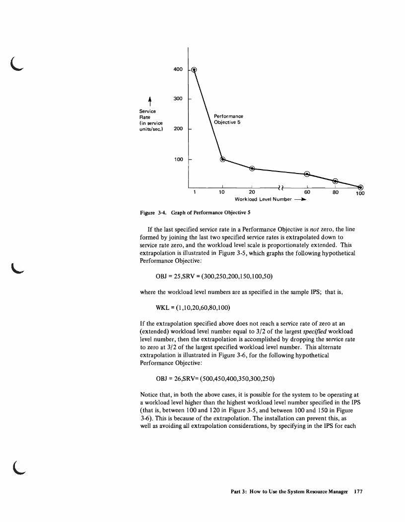
400
t 300
Service Rate (in service units/sec.) 200
100
10 20 Workload Level Number ~
Figure 3-4. Graph of Performance Objective 5
If the last specified service rate in a Performance Objective is not zero, the line formed by joining the last two specified service rates is extrapolated down to service rate zero, and the workload level scale is proportionately extended. This extrapolation is illustrated in Figure 3-5, which graphs the following hypothetical Performance Objective:
OBJ = 25,SRV = (300,250,200,150,100,50)
where the workload level numbers are as specified in the sample IPS; that is,
WKL = (I,10,20,60,80,100)
If the extrapolation specified above does not reach a service rate of zero at an (extended) workload level number equal to 3/2 of the largest specified workload level number, then the extrapolation is accomplished by dropping the service rate to zero at 3/2 of the largest specified workload level number. This alternate extrapolation is illustrated in Figure 3-6, for the following hypothetical Performance Objective:
OBJ = 26,SRV= (500,450,400,350,300,250)
100
Notice that, in both the above cases, it is possible for the system to be operating at a workload level higher than the highest workload level number specified in the IPS (that is, between 100 and 120 in Figure 3-5, and between 100 and 150 in Figure 3-6). This is because of the extrapolation. The installation can prevent this, as well as avoiding all extrapolation considerations, by specifying in the IPS for each
Part 3: How to Use the System Resource Manager 177

400
300
t Service Rate 200
100
10 20 60 80
Performance Objective 25
100
Workload Level--..
Figure 3-S. Linear Extrapolation of a Perfonnance Objective
500
400
t 300 Service Rate
" 200
100
(120)
Performance Objective 26
"-"-"-"-
" " " " "-, ~
10 20 60 80 100 (120) (140) (150) Workload Level----..
Figure 3-6. "3/2" Scale Extrapolation of a Perfonnance Objective
178 OS/VS2 System Programming Library: Initialization and Tuning Guide (VS2 Release 3.7)
L
Performance Objective the workload level number at which the service rate should fall to zero. This has been done in the sample IPS, where the "cut-off' workload levels (that is, workload levels at which a service rate of zero is first specified) are:
Performance Objective
3 4 5 6 7
Cut-off Workload Level
60 20
100 80 60
When the number of service rates specified in the Performance Objective is fewer than the number of specified workload level numbers (as in Performance Objectives 3,4,6, and 7 in the sample IPS), the Performance Objective is completed by performing extrapolation as described above where necessary. When zero has been entered as the service rate, the specification of that particular performance objective should be ended, without attempting to continue the specification to any further workload levels. Although it is syntactically possible to specify a zero service rate for multiple workload levels, the meaning of such usage is undefined. In the initial workload manager implementation, the last (highest) workload level indicated is used as the workload level corresponding to a service rate of zero.
Performance Groups
Performance groups are unique specificatiOns of methods of treating different classes of users. All batch job steps and time sharing terminal sessions are associated with a performance group by the specification of a performance group number (pERFORM = nnn) on the JOB or EXEC statement, in the LOGON command in the RESET or by default. Batch users default to performance group 1; time-sharing users default to performance group 2.
The performance group specifies the treatment an installation wishes the job, step, or time-sharing session to receive at all times, and under particular system workload conditions, by associating the user's transaction(s) with a particular performance objective for each point in the life of the transaction(s). In the sample IPS, performance group 2 is defined as:
PGN = 2, (OBJ = 5, DUR = 100, ISV = 100, RTB = 0) (OBJ = 6, DUR = 900, ISV = 500, RTB = 0) (OBJ = 7, ISV = lK, RTB = 0)
This defines the performance group in terms of three performance group periods. A performance group period specifies how the associated transaction should be treated for a particular portion of the life of the transaction. Up to 8 performance group periods may be specified for a performance group. In the sample performance group, transactions will be associated with Performance Objective 5 for the first period in their existence, with Performance Objective 6 for the second period in their lives (if they last past a first period) and with Performance Objective 7 for the remainder of their existence (if they last past a second period).
Part 3: How to Use the System Resource Manager 179

In general, a performance group is specified as:
PGN = n, (OBJ = kl' DUR = dl, UNT = ~~~, ISV = iI, RTB = ~~D ~~!d ..)
(OBJ = k2' DUR = d2, UNT = ~~~, ISV = i2, RTB = ~~}) ::r~~~~f specified
( OBJ = kj' ISV = ij , RTB::.: ~ ~ ~) last period specified
where the PGN parameter value (n) represents the performance group number (an integer between 1 and 255), and:
• The OBJ parameter values (k l - k.) specify a valid Performance Objective with whicll the transaction is to bJ associated for the duration of the period. In sample Performance Group 2, ~1 = 6, K2 = 7 and K3 = 8, where 6, 7,
and 8 are all Performance Objectives defined in the sample IPs.
• The DUR parameter values specify the length of the periods, in units specified by the UNT parameter. The permissable range of values for this parameter is 0-999999999 (or 0-999999k). If R is specified for UNT, and the value for DUR is greater than 1,000,000, then 1,000,000 will be substituted for the specified value. The last performance group period in a performance group definition should not contain this parameter, since the period will last for the remainder of the transaction.
• The UNT parameter values specify the units in which the period is to be measured. The possible values for this parameter are S, indicating service units, and R, indicating real-time seconds. The default is S (service units). Thus, since no value is specified for this parameter in either the first or second periods of Performance Group 2, the default value S is taken, and the periods last for 100 and 4000 service units, respectively. If UNT = R were specified for the first period of performance group 2, that period would last until 100 seconds had elapsed.
• The ISV parameter values indicate the interval service values associated with each performance group period. Each ISV specifies a minimum number of service units that a transaction must receive during each interval of real storage occupancy before a swap evaluation is made by the Workload Manager. The range of values for this parameter is 100-999999 (or 999k). If no ISV is specified for a performance group period, an ISV of 100 is assumed for that period.
180 OS/VS2 System Programming Library: Initialization and Tuning Guide (VS2 Release 3.7)

L
• The RTB parameter values specify the response/throughput bias associated with each performance group period. Each RTB value indicates whether or not, for the associated period, deviations from the service rate specified in the Performance Objective may be tolerated in favor of higher system throughput. The possible values for this parameter are 0 and 1. "0" indicates that the Performance Objective should be followed as closely as possible, even at the expense of system throughput. "1" indicates that deviations from the Performance Objective are acceptable in the interest of system throughput, and that for this period, the resource use routines will produce evaluations that will influence swap decisions. The default value for the RTB is "1".
Notice that the last specified period descriptor always describes a period extending for the remainder of the transaction's existence. Therefore no period duration (DUR) or units code (UNT) are specified for this last period.
IEAOPTxx - System Tuning Parameters
The system tuning parameters include two categories of information:
• Resource Factor Coefficients (RFC), and • Resources Manager Constants (RMC).
These parameters affect the functioning of the SRM in its goal of maximizing system throughput.
Resource Factor Coefficients
These are values in the range 0.0 to 9.9 which are used to weight the recommendations produced by the I/O and CPU load adjusting routines (see the topic "Resource Use Routines" earlier in this chapter.) The coefficients are specified as:
[RFC[CPU=x.x] [~~ f IOC=y.y]]
where the value of the CPU parameter specifies the factor by which the recommendation of the CPU Load Adjusting routine is to be multiplied, and the value of the IOC parameter specifies the factor by which the recommendation of the I/O Load Adjusting routine is to be multiplied, in evaluating a particular address space for swapping. The recommendation values of the Workload Manager have an implied RFC of 1.0. Therefore, if the coefficients are specified as:
RFC CPU = 3.0, IOC = 2.0
this means that swapping recommendations of the CPU Load Adjusting routine will have more relative weight in determining a swap decision than recommendations of either the I/O Load Adjusting routine or the Workload Manager.lt also means that, though recommendations of the I/O Load Adjusting routine will have less relative weight than those of the CPU Load Adjusting routine, they will have a greater relative weight than the recommendations of the Workload Manager.
The default value for both the CPU and IOC coefficient is 1.0.
Part 3: How to Use the System Resource Manager 181

Resource Manager Constants
This category consists of the Enqueue Residence Value (ERV). The ERV is an integer in the range 0-999999 which is used to calculate the amount of CPU execution time for which an address space should not be swapped out of real storage, when the address space is enqueued upon a system resource required by another address space (see the topic "Resource Use Routines" earlier in this chapter.) The ERV is specified as: ... ".
[RMC[ERV = xxxxxx]]
The time interval is determined by multiplying the ERV by the model dependent time required to execute 10,000 machine instructions. This interval is calculated in terms of machine instructions so that it will remain relatively constant on all System/370 models. Therefore, if the ERV is specified as:
RMC ERV = 2
and the CPU can execute 10,000 instructions in 10 milliseconds, then the address space enqueued upon a resource in demand by other address spaces will be permitted to execute for 20 milliseconds (the time required to execute 20,000 machine instructions) before it will be considered to be available for swap out.
The default value for the ERV is 1.
Other SRM Constants
Although the primary mechanism for controlling the SRM is modification of the ..J PARMLIB members IEAOPTxx and IEAIPSxx, there are other internal constants that govern SRM functioning. Because it is not anticipated that the typical instal-lation will change these values, they can be modified only by changing SRM code itself. These values are all contained in the SRM constants module, IRARMCNS. Figure 3·7 identifies those constants most directly associated with the functions of the resource use routines, as described previously in the topic "Resource Use Routines". Figure 3-8 identifies those constants most directly associated with the Workload Manager and control.
182 OS/VS2 System Programming Library: Initialization and Tuning Guide (VS2 Release 3.7)

Constant Control Block Related Routine Function Initial Value
ICCEDSUT I/O Control Table Device Allocation Projected impact on logical 5% Adjustments to this value: (lCT) (sysevent 28) channel utilization of one an increase tends to encourage
previously allocated data the spreading of each user's set. This amount is added I/O load across several logical to the measured utilization channels, while a decrease for each data set already tends to encourage the allocated to a user on a clustering of each user's load logical channel. The logical on a few logical channels. channel with the lowest adjusted uti lization is given preference for the next allocation choice for the same user.
ICCHIUTH I/O Control Table I/O Load Adjusting Percentage of delayed I/O Initialized by NIP to the value (lCT) requests above which a of ICCINHI1 (70%) for a uni-
logical channel is con- processing system, and to side red to be overutilized. ICCINHI2 (80%) for a
multiprocessor system.
ICCLOUTH I/O Control Table I/O Load Adjusting Percentage of delayed I/O Initialized by NIP to the value (lCT) requests below which a of ICCI NL01 (30%) for a uni-
logical channel is considered processing system, and to to be underutilized. ICCINL02 (40%) for a
multiprocessor system.
ICCSIGUP I/O Control Table I/O Load Adjusting Percentage of I/O requests 5% (lCT) to a logical channel which
must be attributable to a single user before it is con-sidered a heavy user of that channel, and hence eligible for swapping to correct a channel imbalance.
L ICCMNLIN I/O Control Table I/O Load Adjusting Minimum elapsed time before 2000 milliseconds
(lCT) a logical channel utilization computation will take place.
ICCMNUIN I/O Control Table I/O Load Adjusting Minimum elapsed time before 10,000 millisaconds (lCT) a user I/O rate computation
will take place.
ICCMXICT I/O Control Table I/O Load Adjusting Maximum elapsed time a 60,000 milliseconds (lCT) heavy I/O user may remain
in real storage without hav-ing its I/O usage monitored.
CCCUTHIT CPU Management CPU Load Adjusting Percentage of time any 100% Control Table (CCT) CPU was not in the wait
state, above which CPU will be considered overutilized.
CCCUTLOT CPU Management CPU Load Balancing Percentage of time any CPU 80% Control Table (CCT) was not in the wait state,
below which CPU will be considered underutilized.
CCCAPDIV CPU Management Automatic Priority Width, in milliseconds, of a 2 (i.e., users in subgroup n Control Table (CCT) Group (APG) subgroup within the auto- have a mean time to wait
matic priority group. 2 ms. greater than those in subgroup n+1.) (Note 1)
CCCAPRHT CPU Management Automatic Priority Percentage of APG users 60% Control Table (CCT) Group (APG) whose priority must change
at an invocation of this routine, before the routine invocation interval is shortened.
Note 1: The initial value is adjusted by NIP based on CPU model. Values given are for Model 155 MOD II.
L I Figure 3-7. SRM Constants Related to the Resource Use Routines (part 1 of 4)
Part 3: How to Use the System Resource Manager 183
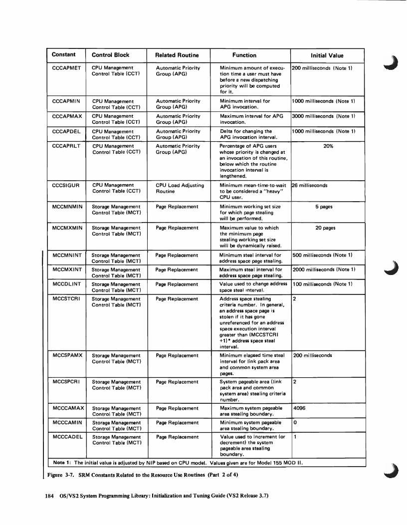
Constant Control Block Related Routine Function Initial Value
CCCAPMET CPU Management Automatic Priority Minimum amount of execu- 200 milliseconds (Note 1) Control Table (CCT) Group (APG) tion time a user must have
before a new dispatching priority will be computed for it_
CCCAPMIN CPU Management Automatic Priority Minimum interval for 1000 milliseconds (Note 1) Control Table (CCT) Group (APG) APG invocation_
CCCAPMAX CPU Management Automatic Priority Maximum interval for APG 3000 milliseconds (Note 1) Control Table (CCT) Group (APG) invocation.
CCCAPDEL CPU Management Automatic Priority Delta for changing the 1000 milliseconds (Note 1) Control Table (CCT) Group (APG) APG invocation interval.
CCCAPRLT CPU Management Automatic Priority Percentage of APG users 20% Control Table (CCT) Group (APG) whose priority is changed at
an invocation of this routine, below which the routine invocation interval is lengthened.
CCCSIGUR CPU Management CPU Load Adjusting Minimum mean-time-to-wait 26 milliseconds Control Table (CCT) Routine to be considered a "heavy"
CPU user.
MCCMNMIN Storage Management Page Replacement Minimum working set size 5 pages Control Table (MCT) for which page stealing
will be performed.
MCCMXMIN Storage Management Page Replacement Maximum value to which 20 pages Control Table (MCT) the minimum page
stealing working set size will be dynamically raised.
MCCMNINT Storage Management Page Replacement Minimum steal interval for 500 milliseconds (Note 1) Control Table (MCT) address space page stealing.
MCCMXINT Storage Management Page Replacement Maximum steal interval for 2000 milliseconds (Note 1) Control Table (MCT) address space page stealing.
MCCDLlNT Storage Management Page Replacement Value used to change address 100 milliseconds (Note 1) Control Table (MCT) space steal interval.
MCCSTCRI Storage Management Page Replacement Address space stealing 2 Control Table (MCT) criteria number. In general,
an address space page is stolen if it has gone unreferenced for an address space execution interval greater than (MCCSTCR I +1) * address space steal interval.
MCCSPAMX Storage Management Page Replacement Minimum elapsed time steal 200 mi lliseconds Control Table (MCT) interval for link pack area
and common system area pages.
MCCSPCRI Storage Management Page Replacement System pageable area (link 2 Control Table (MCT) pack area and common
system area) stealing criteria number.
MCCCAMAX Storage Management Page Replacement Maximum system pageable 4096 Control Table (MCT) area stealing boundary.
MCCCAMIN Storage Management Page Replacement Minimum system pageable 0 Control Table (MCT) area stealing boundary.
MCCCADEL Storage Management Page Replacement Value used to increment (or 1 Control Table (MCT) decrement! the system
pageable area stealing boundary.
Note 1: The initial valu.a is adjusted by NIP based on CPU model. Values given are for Model 155 MOD II.
Figure 3-7. SRM Constants Related to the Resource Use Routines (part 2 of 4)
184 OS/VS2 System Programming Library: Initialization and Tuning Guide (VS2 Release 3.7)

L Constant Control Block Related Routine Function Initial Value
MCCSPAFC Storage Management Page Replacement Weighing factor for system 140 Control Table (MCT) pageable area page-ins and
page-outs for use in adjusting SPA stealing boundary_ A value of 100 means each SPA page-in or page-out is weighed equally with any other system page-in or page-out.
MCCSWPFC Storage Management Page Replacement Weighing factor for swap 1 Control Table (MCT) page-ins and page-outs used
in computation of system paging rate in SPA stealing boundary adjustment. Setting this constant to zero excludes swap I/O from the system paging rate.
MCCVIOFC Storage Management Page Replacement Weighing factor for VIO 1 Control Table (MCT) page-i ns and page·outs used
in computation of system paging rate in SPA stealing boundary adjustment. Setting this value to zero excludes VIO paging from the system paging rate.
MCCSTLFC Storage Management Page Replacement Weighing factor for all non- I Control Table (MCT) swap and non-VIO page-ins
and page-outs used in computation of system paging rate in SPA stealing boundary adjustment.
MCCSYSDP Storage Management Page Replacement System memory dispatching 254 Control Table (MCT) priority. Non-swappable
address spaces with dispatch-ing priorities greater than MCCSYSDP have pages stolen on an elapsed time basis.
MCCDLMIN Storage Management Page Replacement I ncrement for dynamically 1 page Control Table (MCT) adjusting the minimum page
stealing working set size.
MCCLOWHT Storage Management Main Storage % of time that number of 10% Control Table (MCT) Occupancy free rea I page fra mes may
fall below the limit before the target value for the number of free real frames is raised.
MCCLOWLT Storage Management Main Storage % of time that number of 2% Control Table (MCT) Occupancy free real page frames may
fall below the limit before the target value for the number of free real frames is lowered.
MCCTARMN Storage Management Main Storage Minimum value for target 10 Control Table (MCT) Occupancy number of free real page
frames.
MCCTARMX Storage Management Main Storage Maximum value for target Initialized by NIP to a value Control Table (MCT) Occupancy number of free real page 30% of the total frames
frames. available to users.
L I Figure 3-7. SRM Constants Related to the Resource Use Routines (part 3 of 4)
Part 3: How to Use the System Resource Manager 185

Constant Control Block Related Routine Function Initial Value
MCCTOL Storage Management Main Storage Length of time in the future 56.66 Control Table (MCT) Occupancy which determines which "to-
be-swapped-in" working sets will be taken into considera-tion in determining"'present" utilization of real storage.
MCCMXPTR Storage Management Main Storage Maximum page transfer 32 pages per second. Control Table (MCT) Occupancy rate: page I/O per
second due to stealing, not including VIO or swaps. If measured page transfer is less than this maximum value, page shortages will be relieved by page stealing instead of swapping.
MCCPTINT Storage Management Main Storage I nterval length for page 4000 milliseconds (Note 1) Control Table (MCT) Occupancy transfer computation.
MCCASMT1 Storage Management Auxiliary Storage %of allocated auxiliary 70% Control Table (MCT) Shortage Detection storage slots defining a
leve 1-1 shortage.
MCCASMT2 Storage Management Auxiliary Storage % of allocated auxiliary 85% Control Table (MCT) Shortage Detection storage slots defining a
level-2 shortage.
Note 1: The initial value is adjusted by NIP based on CPU model. Values given are for Model 155 MOD II.
Figure 3-7. SRM Constants Related to the Resource Use Routines (part 4 of 4)
186 OS{VS2 System Programming Library: Initialization and Tuning Guide (VS2 Release 3.7)

Constant Control Block Related Routine Function Initial Value
RMPTIMN Resources Manager Workload Manager Default value for Interval 100 service units Parameter Table (RMPT) Service Value (lSV) parameter
in Installation Performance Specification (I PS).
RMPTSMX Resources Manager SRM Control Maximum interval for 15000 millisecond Parameter Table (RMPT) invocation of SRM control (Adjusted during IPL based
analysis routine. on CPU model.)
RMPTSTI Resources Manager SRM Control Threshold value that the o !times a scaling factor Parameter Table (RMPT) composite swap-in of 256)
recommendation must exceed before an attempt is made to swap-in a user.
RMPTSTO Resources Manager SRM Control Threshold value that the 256 !times a scaling factor Parameter Table (RMPT) composite swap-out of 256)
recommendation must exceed before an attempt is made to swap-out a user at a time when t~ere is no demand for the u,ser's real storage.
RMPTTOM Resources Manager SRM Control Minimum interval for 500 milliseconds Parameter Table (RMPT) scheduling SRM timer
expiration.
RMPTVMX Resources Manager Workload Manager Threshold value for Interval 160 service units Parameter Table (RMPT) Service Value (lSV) in first
period of a TSO group in the Installation Pe,rformance Specification (IPS>' TSO users with ISV values lower than the threshold are given preference for a swap-in.
RMPTVTM Resources Manager Workload Manager Time delay threshold above 5000 milliseconds Parameter Table (RMPT) which TSO users are not given
preferential treatment via RMPTVMX.
Figute 3-8. SRM Constants Related to the Workload Manager and Control
L Part 3: How to Use the System Resource Manager 187

Guidelines for Defining SRM Parameters
When a change is made to a parameter that affects the functioning of the SRM, the ...J actual result is not simple to predict. It depends on the total system environment; that is, it depends on the values of other governing parameters, as well as the system load. Results are difficult to predict because the SRM itself is a decision maker, and a change to one of its parameters will influence, though not dictate, its final decision. Therefore, SRM parameters should be modified by an iterative process of making changes, then observing the effect of the changes (for example, by use ofMF/l, GTF or SMF), and then making further refinements, as needed, to meet the installation's objectives. The following sections indicate the nature of possible changes to achieve particular results. For ease of understanding, the changes are considered to be made in isolation; that is, by keeping all other system variables constant (other SRM parameters, system load, etc.).
Changing the Installation Perfonnance Specification (PARMLIB Member IEAIPSxx)
The changes which might be made in modifying an existing IPS include:
• Adding a new performance group. • Modifying an existing performance group, including:
Changing a performance objective. - Changing the RTB - Changing the ISV.
• Changing the workload level numbers. • Changing the service definition coefficients.
Adding a New Perfonnance Group
This change may be required when a class of users is identified which requires unique treatment. This may be, for example, because some subgroup of users, belonging to an existing performance group, finds that their turnaround or response requirements are not met during normal system operation, whereas the remaining members of that performance group are satisfied with the service rates that the associated performanceobjectives are providing them. Alternately, the installation may determine that a subgroup of users, by being placed in any of the existing performance groups, receives a service rate in excess of that which need be provided to it.
Mechanics of the Change: The installation selects a new performance group number, not previously associated with any valid performance group, and informs the class of users that this is the value they should use for their PERFORM parameter. Then the installation creates a new IEAIPSxx member which includes a definition of the new performance group. (See "Performance Groups" in the topic "IEAIPSxx-IPS Parameters.) The installation places the new IPS into operation by identifying the newly created P ARMLIB member in the SET command, or by means of parrnlib member IEASYSOO or IEASYSxx during system initialization.
188 OS!VS2 System Programming Library: Initialization and Tuning Guide (VS2 Release 3.7)

In defining the new performance group, the installation must analyze the characteristics of the user class, as well as the nature of the treatment desired. It may be that performance objectives already exist which adequately define the service rate requirements of this user class. In this case, creating the new performance group definition will be a process of identifying one or more periods, and associating each period with an existing performance objective.
Periods may be identified by analyzing past service requirements of users in the class. If 95% of the users in the class have been requiring less than a fixed number of service units to complete their processing, and the remaining users substantially more service units, the installation may wish to define a first period whose duration is equal to that fixed number of service units. A second period could then be defined during which transactions would be associated with a lower performance objective. In this manner a particular subgroup could be given a lower service rate after an initial period of good service. In the initial period, most related users would have completed their processing.
If no performance objectives exist which adequately define the service rate requirements of this user class, new ones must be defined. The definitions of performance objective, response/throughput bias, and interval service value are discussed later under the heading "Modifying a Performance Group."
Related Considerations: If a significant group of users are changed to a new performance group, the change can have a measurable effect on the system workload level, even though no individual performance objective has changed. For example, consider the IPS with performance objectives as shown in Figure 3-9, and the following three performance group definitions:
PGN=I,(OBJ=I) PGN=2,(OBJ=2) PGN=3,(OBJ=3)
Suppose now that the installation defines a new performance group as follows:
PGN=4,(OBJ=I,DUR=10K),(OBJ=3)
If a substantial number of users who previously ran under performance group 1 now run associated with performance group 4, and a substantial number of these require more than 10,000 service units to complete a transaction, then at any given time, there should be fewer active transactions associated with performance objective 1 than previously, but more active transactions associated with performance objective 3. This should have the effect oflowering the composite demand on system resources, since users associated with performance objective 3 require a lower service rate than those associated with performance objective 1, under most system workload conditions. Thus, all other factors being equal, the usual system workload level will be lower, and the service rate provided to address spaces associated with any performance objective will be greater. This would mean that all transactions would complete faster than previously, except for those associated with performance group 4 which require more than 10,000 service units to complete. These would complete slower than before, since they would drop to performance objective 3 after completion of the first period.
Part 3: How to Use the System Resource Manager 189

400
300
t Service R.ate
200
100
Usual System Workload Level
20
Workload Level ~
Figure 3·9. Sample Perfonnance Objectives
40
Alternately, if a substantial number of transactions that previously ran associated with performance group 3 now run associated with performance group 4, the usual system workload level should rise. The reason is that there are more transactions associated with performance objective I than previously, placing a correspondingly greater demand on system resources.
Modifying a Performance Group
This change may be required when the service afforded some class of system users, as specified in a performance group definition, is not meeting some installation or user requirement. This may be because a performance objective associated with some performance group period does not properly state the relative importance of this group with respect to some other group or groups, under some system workloads. For example, the last performance group period may be associated with a low performance objective, when the installation actually wishes associated jobs that have not completed within a certain time to have an increased priority, and so to be associated with a high performance objective. An unsatisfied installation requirement may also relate to a desire to improve system throughput even at the possible expense of some performance requirements of transactions associated with a particular performance group.
A performance group may be changed by changing related performance objectives, or by changing response/throughput bias values, or by changing interval service values. Each of these changes will be discussed separately.
190 OS/VS2 System Programming Library: Initialization and Tuning Guide (VS2 Release 3.7)

Changing a Perfonnance Objective: A performance objective change may be required when it is determined that members of a performance group should receive a different service rate at some (or all) workload levels at some point in the processing of their transactions.
Mechanics of the Change: The performance objective associated with a transaction can be changed by adding more period descriptors to a performance group definition, thereby dynamically associating the transaction with a new performance objective during the transaction's processing. For example, suppose performance group 1 is defined Its:
PGN = 1, (OBI = 3)
If the installation decides that it wishes to lower the service rate demands of any performance group-l transactions still processing after accumulating 10,000 service units, it can accomplish this by redefining performance group 1 as:
PGN= 1,(OBl=3,OUR= 10K) (OBl=4)
where performance objective 4 is an existing performance objective with lower service rate requiremertts than performance objective 3.
The performance objective associated with a transaction can be changed without modifying the performance group definition, by changing the definition of the performance objective itself. For example, if performance group 1 is defined as
PGN= 1,(OBJ=3)
and performance objective 3 is defmed as
OBI = 3, SRV = (450,450,450,0)
then the service rate requirements of all transactions associated with performance group 1 can be lowered by redefining performance objective 3 as
OBJ = 3, SRV = (350,350,350,0).
If, however, the desire is to lower the service rate requirements of transactions associated with performance group 1, and only performance group 1, this latter method (changing a related performance objective) can have undesirable side effects. For example, suppose there is also a performance group 30, defined as:
PGN = 3ID, (OBI = 2, OUR = 8K) (OBI = 3, OUR = 15K) (OBl=4)
Part 3: How to Use the System Resource Manager 191

In this case, the change made to performance objective 3 will affect not only performance group I, as desired, but also performance group 30 transactions. This is because transactions in the second performance group period of performance group 30 are also associated with performance objective 3. The solution to this problem is to create a new performance objective with the desired qualities, rather than to change an existing performance objective. For example, if performance objective number 31 has not been used in the IPS, the installation could define performance objective 31 as
OBJ = 31, SRV = (350,350,350,0)
and redefine performance group 1 as
PGN = 1, (OBJ = 31).
In creating a new performance objective, or modifying an existing one, the most critical points to consider are those associated with the following three workload levels:
• The workload level at which the system most frequently operates (normal system workload level).
• The workload level at which associated transactions are to stop receiving service (cut off workload level).
• The lowest specified workload level.
These three workload levels are illustrated for a performance objective (here performance objective 2) in Figure 3-10. The service rate specified at workload level 2, the lowest specified workload level, should be high enough that no associated transaction can ever absorb service at this rate. (Notice that absorption rate - the maximum service rate a given transaction can absorb - is determined by the Service Definition Coefficients, as well as by the characteristics of the transaction.) This is because at workload level 2 there is little if any contention for system resources, so that there is no obvious reason for swapping a related transaction, from a workload management point of view. To guard the user from specifying too Iowa service rate at the lowest specified workload level, the SRM will assume an extremely high service rate at the dummy workload level of zero, as indicated by the dotted extrapolation in Figure 3-10. However, this zero-workload extrapolation, which extends to points below the lowest specified workload level (2), produces little or no distinction among performance objectives. By assigning explicit high service rates to the lower specific workload levels, the installation can maintain distinction among various performance objectives even when the system load is very light.
The normal system workload level, as indicated in the MF/l workload activity report, is the point about which the system workload normally hovers. The service rate specifications at this system workload level are extremely important because they indicate the normal relative importance of system transactions. Similarly, cutoff workload levels are important in specifying the relative priority of transactions: less important transactions are cut off at lower workload levels than more important ones so that, as demand for system resources increases, unimportant transactions will be sacrificed for important ones. This is illustrated in Figure 3-11. At a system workload level of 40, transactions associated with performance objective 21 will be cut off in favor of transactions associated with performance objective 22
192 OS/VS2 System Programming Library: Initialization and Tuning Guide (VS2 Release 3.7)

t Service Rate
400
300
200
100
40
I System I Workload I Level
I I I I I I I I I I I I
60
Workload Level ~
Cut Off Workload Level
80
WKL = (2,40,60,80,100) OBJ = 2, SRV = (400,
100,50,0)
100
Figure 3-10. mustration of Key Workload Levels for a Perfonnance Objective
WKL = (2,40,60,80, 1(0) OBJ = 21, SRV = (400,0) OBJ = 22, SRV = (400, 150,0) OBJ = 23, SRV = (400,220, 110,0) OBJ = 24, SRV = (400,400,250,130,0)
400
t 300 Service Rate
200
100
2 40
("") c ... ~
Note that the service rate of 400 is above the maximum absorption rate.
60 80 100
("") ("") ("") c c c ... ... ... ~ ~ ~ .... 1'0) w ""
Workload Level ~
Figure 3-11. illustration of Different Perfonnance Objective Cut-offs
Part 3: How to Use the System Resource Manager 193

(receiving 150 service units/second), performance objective 23 (receiving 220 service units/second), and performance objective 24 (still receiving 400 service units/second). At workload level 60, transactions associated with performance objective 22 stop receiving service. And at a system workload level of 80, all transactions except those associated with performance objective 24 will have stopped receiving service.
Related Considerations: It must be remembered that changing a performance objective will have system-wide repercussions. Since the system's supply of resources is limited, increased demand on the part of some transactions, indicated by raised performance objectives, will result in lowered supply to other transactions (assuming that there is no system contention bottleneck, and assuming that the transactions whose demand is raised can absorb an increased service rate). Figure 3-12 illustrates this effect. When performance objective 21 is raised, transactions associated with it receive a higher service rate, and transactions associated with performance objective 24 receive a lower service rate; the system workload level rises correspondingly. As before, this assumes identity of system environment, no contention bottleneck, and the capability of performance objective 21 transactions to absorb the higher service rate.
400
t 300
Service Rate
200
100
2
System (Raised System Workload Workload Levell Level I
I I
---I 1
I When performance objective
~ X~l 21 is raised. the system workload level increases.
" I
" 1 % ~ 1 \\ " I ~ "I
'\..
~ /I ""O~
"v~ I ~'/ I "
40 60 80
Workload Level ---+ 100
Figure 3-12. Raising a Performance Objective
194 OS/VS2 System Programming Library: Initialization and Tuning Guide (VS2 Release 3.7)

Changing the Response/Throughput Bias (RTB)
A change in the RTB may be dictated when the installation determines that transactions in a particular performance gro'up period must adhere closely to their stated performance objective, even at the expense of system throughput considerations. Alternately, the installation may determine that close adherence to stated performance objectives should be sacrificed in the interests of system throughput, for transactions in a particular performance group period,
Mechanics of the Change: To follow a performance objective as closely as possible, the installation should set the RTB value in the period descriptor(s) to "0". To allow deviations in the interest of system throughput, it should set the RTB value to "1",
For example, if a performance group is defined as
PGN=2, (OB1=6,DUR=400,RTB=0) Period One (OB1=7 ,DUR=4K,RTB=0) Period Two (OB1=8,RTB=0) Period Three
the installation may determine that associated transactions that last long enough to enter the third performance group period, can afford to follow performance objective 8 less closely in the interests of system throughput. In this case, performance group 2 can be redefined in the new IPS are:
PGN=2, (OB1=6,DUR=400,RTB=0) Period One (OB1=7,DUR=4K,RTB=0) Period Two (OB1=8,RTB=1) Period Three
Related Considerations: Even those transactions associated with RTB values of "0" will be indirectly affected if a Significant number of active transactions are associated with RTB values of" 1". This is because a widespread use of RTB value of 1 should have a positive effect on overall system throUghput.
Changing the Interval Service Value (ISV): The installation may wish to increase the ISV for a class of transactions in order to lessen the swapping of these transactions, in the interests of system throughput, Alternately, the installation may wish to modify the ISV associated with a class of time-sharing transactions in the hope of increasing the chance of the transactions completing their processing on the initial real storage residence interval (that is, before a swap-out), thereby improving realted time-sharing response time.
Mechanics of the Change: For batch transactions, improvements in system throughput through reduced swapping is the primary goal of an ISV increase. These changes can be made by iterative changes in ISVs associated with performance group periods where the associated transactions need not follow the performance objective too closely. The basis for further iteration can be obtained from relevant MF/l reports.
Part 3: How to Use the System Resource Manager 195

For time-sharing transactions, response time is an additional consideration. Analysis of numbers of service units required for specific time-sharing processing can form the basis for ISV modification. SMF data is useful here.
Related Considerations: In general, a specified ISV should not be larger than the expected transaction duration. This is especially important for TSO transactions where too large an ISV value can have an undesirable effect on response time.
In general, for TSO performance groups where response is an important consideration, the first period should not have an ISV greater than 160 service units.
Changing the Workload Level Numbers
The installation can change the workload level numbers specified in an IPS to provide more discrimination between differing performance objectives, thus allowing more precise control by the workload manager.
Mechanics of the Change: A broadening of the scale of workload level numbers provides greater discrimination between performance objectives. Thus, if the workload levels are defined as:
WKL=(10,20,30,40,50)
this is equivalent to a specification of
WKL=(1,2,3,4,5)
because the SRM divides each workload level by the first specified level. An expansion of the scale can be effected by redefining the workload level numbers as:
WKL=(1,20,30,40,50)
which cannot be further reduced.
Related Considerations: Expansion of the range of workload level numbers can result in the following:
• Closer adherence to performance objectives. • Some decrease in total system throughput because of the closer control (that
is, some additional swapping overhead).
Refer to Figure 3-13 for a Simplified example of an IPS that illustrates the effect of expanding the range of workload level numbers.
196 OS/VS2 System Programming Library: Initialization and Tuning Guide (VS2 Release 3.7)

L
I Service Rate
CPU=1.0,IOC=1.0,MSO=1.0 WKL=( 1,2,4,6)
OBJ=1,SRV=(400,400, * ,0) PGN=1,(OBJ=1 )
Figure 3-13. IPS AA
400
300
200
100
User A System Workload Level
User B
2 4 6
Workload Level Number ~
As in the example illustrated in Figure 3-13, there are two identical users, A and B, only one of which can occupy main storage at the same time though both absorb service at a rate of 400 service units per second when in real storage. In the absence of resource recommendations, if user A is in real storage, user A will not be swapped out to bring in user B unless user B's workload level exceeds user A's workload level by a value greater than some threshold (which is assumed to be 4 for this example). To exceed the swap threshold of 4 (workload level 6 minus workload level 4), the service rates of the two users must differ by at least 400 service units per second. With an absorption rate of 400, this difference can be reached at most once a second, giving a maximum rate of one per second for swapping users A and B. If both users entered the system at the same time, user A will get at least 400 service units per second ahead of user B before a swap occurs.
In Figure 3-14, the workload level is expanded by a factor of 10, with everything else the same. The swap threshold remains the same at 4. But now to reach it, the service rate of user A must only be 220 minus 180, or 40 (not 400) service units greater than user B's service.rate. The users' absorption rates have not changed (400 service units per second). Therefore, making the same assumptions as before, the threshold difference of 4 workload levels can now be reached once every .1 (40/400) second. This means the maximum rate for swapping is 10 per second instead of the previous one per second. Now user A will get only 40 service units per second ahead of user B before a swap can be made by the Workload Manager.
Part 3: How to Use the System Resource Manager 197

CPU=1.0,1 OC=1.0,MSO= 1.0 WKL=( 1,20,40,60)
OBJ=1,SRV=(400,400, * ,0) PGN=1,(OBJ=1 )
Figure 3-14. IPS BB
Notes on Changing the Slope of the Objective: Because IPS AA slopes steeply (that is, decreases 400 service units in 4 workload levels), the IPS would preferably \ be used by an installation that is not primarily concerned with service rate ..., distinction among users. A gradual slope (see IPS BB, Figure 3-14) allows for more service rate distinction among users. Because IPS BB slopes gradually (that is, decreases 400 service units in 40 workload levels) the IPS would preferably be used by an installation that is concerned with service rate distinction among users. A steep type of slope (see IPS AA, Figure 3-13) allows for less service rate distinction among users.
Changing the Service Defmition Coefficients
The installation may wish to change the service defmition coefficients in order to better control the performance of transactions that use widely differing proportions of the three basic resources (CPU, I/O, and real storage). For example, even though an extremely I/O bound job makes relatively little use of the CPU, the fact that it does a great deal of I/O will result in a significant accumulation of service if the value of IOC is not zero. This in turn means that when both a CPU bound and an I/O bound job absorb service at roughly the same rate, both can be controlled by the same service rate objective (that is, both can be associated with the same performance objective). Therefore, the installation will often wish to choose values for the three service defintion coefficients such that the service absorption rates (the upper bound of a transaction's service rate) of extremely CPU oriented transactions are apprOximately the same the service absorption rates of extremely I/O oriented transactions.
198 OS/VS2 System Programming Library: lnitUilization and Tuning Guide (VSl Release 3.7)
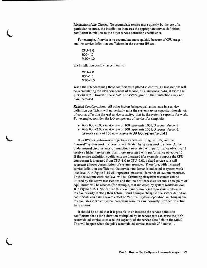
Mechanics of the Change: To accumulate service more quickly by the use of a particular resource, the installation increases the appropriate service definition coefficient in relation to the other service definition coefficients.
For example, if service is to accumulate more quickly because of CPU usage, and the service definition coefficients in the curren tIPS are:
CPU=1.0 IOC=1.0 MSO=1.0
the installation could change them to:
CPU=2.0 IOC=1.0 MSO=1.0
When the IPS containing these coefficients is placed in control, all transactions will be accumulating the CPU component of service, on a numerical basis, at twice the previous rate. However, the actual CPU service given to the transactions may not have increased.
Related Considerations: All other factors being equal, an increase in a service definition coefficient will numerically raise the system service capacity, though not, of course, affecting the real service capacity; that is, the system's capacity for work. For example, consider the I/O component of service, for simplicity:
• With IOC=1.0, a service rate of 100 represents 100 I/O requests/second. • With IOC=2.0, a service rate of 200 represents 100 I/O requests/second.
(A service rate of 100 now represents 50 I/O requests/second.)
If an IPS has performance objectives as defined in Figure 3-15, and the "normal" system workload level is as indicated by system workload level A, then under normal circumstances, transactions associated with performance objective 11 receive a higher service rate than those associated with performance objective 12. If the service definition coefficients are increased (for example, suppose the CPU component is increased from CPU=l.O to CPU=2.0), a fixed service rate will represent a lower consumption of system resources. Therefore, with increased service defmition coefficients, the service rate demands indicated at system workload level A in Figure 3-15 will represent less actual demands on system resources. Thus the system workload level will fall (assuming all system resources can be utilized by the active transactions and that no bottlenecks exist) and a new point of equilibrium will be reached (for example, that indicated by system workload level B in Figure 3-15.) Notice that this new equilibrium point represents a different relative priority ranking than before. Thus a simple change in the service definition coefficients can have a severe effect on "normal" system operation, in changing the relative rates at which system processing resources are normally prOVided to active transactions.
It should be noted that it is possible to so increase the service definition coefficients that a job's duration multiplied by its service rate can cause the job's .. accumulated service to exceed the capacity of the service data field in the SRM. This will happen when the job's accumulated service exceeds 2 31 minus 1.
Part 3: How to Use the System Resource Manager 199
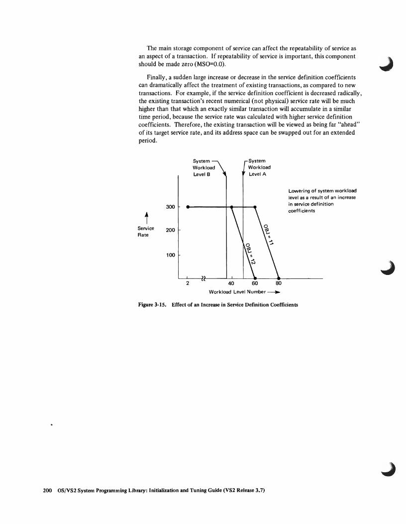
The main storage component of service can affect the repeatability of service as an aspect of a transaction. If repeatability of service is important, this component should be made zero (MSO=O.O).
Finally, a sudden large increase or decrease in the service definition coefficients can dramatically affect the treatment of existing transactions, as compared to new transactions. For example, if the service definition coefficient is decreased radically, the existing transaction's recent numerical (not physical) service rate will be much higher than that which an exactly similar transaction will accumulate in a similar time period, because the service rate was calculated with higher service definition coefficients. Therefore, the existing transaction will be viewed as being far "ahead" of its target service rate, and its address space can be swapped out for an extended period.
300
t Service 200 Rate
100
2
System Workload Level B
40
System Workload Level A
60 80
Workload Level Number ~
Lowering of system workload level as a result of an increase in service definition coefficients
Figure 3-15. Effect of an Increase in Service Definition Coefficients
200 OS/VS2 System Programming Library: Initialization and Tuning Guide (VS2 Release 3.7)

Changing the System Tuning Parameters (P ARM LIB member IEAOPTxx)
The changes that might be made in modifying the system tuning parameters are:
• Changing the resource factor coefficients, or • Changing the enqueue residence value.
Changing the Resource Factor Coefficients (RFC)
This change may be made when an installation decides that it wishes to place a greater or smaller emphasis on the prevention of imbalances in system CPU or I/O r:esources.
Mechanics of the Change: If the installation wants to reduce resource imbalances of a particular type, it increases the associated RFC (CPU or IOC) above its default value of 1.0. If it wants to indicate that particular imbalances should be less of a consideration in swapping address spaces, it lowers the associated RFC.
Related Considerations: (none identified.)
Changing the Enqueue Residence Value (ERV)
This change may be made when the installation wishes to increase or decrease the amount of time that an address space is treated as nonswappable when it is enqueued upon a resource that is in demand by another address space.
Mechanics of the Change: The value specified in the ERV is increased to increase the amount of execution time during which the transaction should not be swapped out, and is decreased to diminish the amount of this preferential service.
Related Considerations: (none identified)
Part 3: How to Use the System Resource Manager 201

202 OS/VS2 System Programming Library: Initialization and Tuning Guide (VS2 Release 3.7)

L
L
L
Part 4: How to Use the System Activity Measurement Facility (MF/l)
The System Activity Measurement Facility (MF /1) is an analysis tool which an installation may use to monitor selected areas of system activity, and obtain feedback in the form of SMF records and/or formatted reports. MF /1 permits the gathering of information on the following classes of system activity, either indiVidually or in combination:
• CPU activity
• Channel activity and channel-CPU overlap activity
• I/O device activity and contention for: - Unit record devices - Graphics devices - Direct access storage devices - Communication equipment - Magnetic tape 'devices - Character reader devices
• Paging activity
• Workload activity
With MF/I, an installation can monitor the utilization of individual CPU's, channels and devices, in order to identify system components whose overall utilization is exceptional. The installation can further identify periods of system activity during which the utilization of particular resources are exceptional. Finally, the installation can relate the service being provided to different classes of users to the specifications provided in the Installation Performance Specification (IPS).
MF /1 is a software monitoring tool. Thus it is limited to reporting on system activity as that activity is communicated to the system (for example, by the setting of flags). As a result of this indirect reporting, MF/1 's statistically sampled values can approach in accuracy only the internal system indications, not necessarily the external system activity itself. For example, if a CPU is disabled so that the freeing of a device (device end interruption) cannot be communicated to the system, the device will appear busy for a longer period of time than it would if it were measured by a hardware measuring instrument.
In an installation using the Mass Storage System (MSS), Mass Storage System Trace Report programs are used to monitor the MSS. These programs are described in OS/VS Mass Storage System (MSS) Services for Space Management.
MF /1 Operation
MF /1 is always generated with the system, but its operation is completely optional. The system operator initiates MF/1 monitoring with the START command. MF/1 can also be started as a batch job. When MF/1 is not operating, it will cause little performance or storage overhead. When it is operating, the storage and performance overhead will depend on the set of options which were specified by the operator.
Part 4: How to Use the System Activity Measurement Facility (MF/l) 203
II
The operation of MF / I is controlled by a set of parameters that may be contained in:
• The "parmvalue" field of the START command that is issued to start MF / I processing.
• The PARM field of the EXEC statement in the MF/l cataloged procedure, if used (the IBM-supplied procedure does not use it).
• The MF/l partitioned data set member (typically a SYSl.PARMLIB member).
If a parameter is not specified in any of these sources, a program default value is used.
The MF /1 cataloged procedure is named MFl, and resides in the SYSl.PROCLIB data set. The IBM-supplied procedure is:
//IEFPROC EXEC PGM=IRBMFMFC,DPRTY=(15,15) //IEFRDER DD DSN=SYS1.PARMLIB,DISP=SHR //SYSUDUMP DD SYSOUT=A
The IEFRDER DD statement names the MF /1 library partitioned data set which may contain any number of members, each containing card-image MF /1 control input. The member names must be in the form IRBMFlnn, where nn is a decimal digit field. The default value for nn, "00", may be changed by the MEMBER parameter, as indicated below in the explanation of the MEMBER parameter.
The START and STOP commands used to initiate and terminate MF /1 operation have the following syntax:
START MF1 [.identifierJ [,devicenameJ [,volumeserialJ [,parmvalueJ [,keyword=option , ... J
Note: The identifier, although optional during the starting of MF /1, must have been specified at START in order to STOP MF /1 from the operator's console.
STOP [MF1.J identifier (The STOP command will not take effect until after the "MF / 1 ACTIVE" message has been received by the operator.)
The "parmvalue" field may be unused (if MF /1 control parameters are to be obtained from a lower priority source), or may contain one or more MF /1 options, to be used to control MF /1 for the duration of its execution. If non-alphameric characters are used in this field (for example, when more than one option is specified, and commas are therefore used as separators), the "parmvalue" field must be enclosed in parentheses.
The "devicename" and "volumes erial" fields are used only when the operator desires to override the specifications of the IEFRDER DD statement in the MF /1 cataloged procedure. When these fields are left blank (as will normally be the case), commas must be inserted to indicate their absence ifMF /1 parameters are to be specified in the "parmvalue" field.
204 OS/VS2 System Programming Library: Initialization and Tuning Guide (VS2 Release 3.7)

The "keyword=option" field may be used to specify any special keyword syntax desired for the IEFRDER DD statement, or any symbolic parameter keyword defined when a user-written cataloged procedure replaces the IBM-supplied one. Normally, this field will not be used.
. An example of a typical operator request for MF /1 activity, specifying three MF /1 control parameters, is:
START MF1.EXAMPLE",(WKLD(SYSTEM), CYCLE(100), DEVICE(NOCOMM))
An example of starting MF/l as a batch job is:
//MF1 JOB (accounting information) I/MF1 EXEC MF1
MF/l Options
For a more detailed explanation of parameter selection and syntax rules, refer to the IRBMFxx member description in Part 2: System Initialization.
The MF /1 control options are summarized below. The underlined values are the program default values, and appear in the IBM-supplied SYSl.PARMLIB member IRBMFlOO. The values of these options to control an MF/l execution are taken from the input sources in the following priority order:
1. START command "parmvalue" field
2. EXEC statement PARM field
3. MF/I partitioned data set member
An option explicitly specified in the START command will take priority over any conflicting specifications of that parameter in the EXEC statement, or the MF /1 partitioned data set member. An option explicitly specified in the EXEC statement will take priority over a conflicting specification in the MF/l partitioned data set member. If there are parameters for which no values are specified in the START command, the EXEC statement, or the MF/l partitioned data set member, a program default value will be used.
OPTION
{ CPU } NOCPU
{ CHAN } NOCHAN
{ DEVICE (device list) } NODEVICE
FUNCTION
Specifies whether or not system CPU activity is to be monitored by MF/1.
Specifies whether or not system channel activity is to be monitored by MF/1.
Specifies whether or not system device activity is to be monitored by MF/1. If DEVICE is specified, a device list must indicate the classes of devices that will be monitored.
Part 4: How to Use the System Activity Measurement Facility (MF/n 205
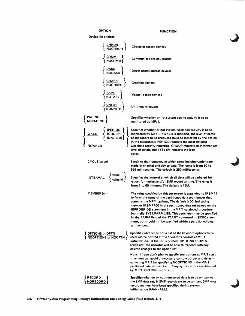
OPTION FUNCTION
Device list choices:
{ CHRDR } NOCHRDR Character reader devices
{ ~~~~MM } Communications equipment
{ ~~~~SD } Direct access storage devices
{ GRAPH } NOGRAPH
{~~~~PE } { UNITR }
NOUNITR
{ PAGING } NOPAGING
{ WKLD {:~~~~~) } }
(SYSTEM)
NOWKLD
CYCLE(value)
INTERVAL { value } value M
MEMBER(nn)
{ OPTIONS or OPTN } NOOPTIONS or NOOPTN
{ RECORD } NORECORD
Graph ics devices
Magnetic tape devices
Unit record devices
Specifies whether or not system paging activity is to be monitored by MF/1.
Specifies whether or not system workload activity is to be monitored by MF 11. If WKLD is specified, the level of detail of the report to be produced must be indicated by the option in the parenthesis. PERIOD requests the most detailed workload activity reporting, GROUP requests an intermediate lell8l of detail, and SYSTEM requests the least detail.
Specifies the frequency at which sampling observations are made of channel and device data, The range is from 50 to 999 milliseconds. The default is 250 milliseconds.
Specifies the interval at which all data will be gathered for report formatting and/or SMF record writing. The range is from 1 to 60 minutes. The default is 15M.
The value specified by this parameter is appended to IRBMF1 to form the name of the partitioned data set member that contains the MF/1 options. The default is 00, indicating member IRBMF100 in the partitioned data set named on the IEFRDER DD statement in the MF/1 cataloged procedure (normally SYS1.PAR MUB!. This parameter may be specified in the PARM field of the START command or EXEC statement, but should not be specified within a partitioned data set member.
Specifies whether or not a list of the keyword options to be used will be printed at the operator's console at MF/1 initialization. If the list is printed (OPTIONS or OPTN specified), the operator will be able to respond with any desired changes to the option list.
Note: If you don't plan to specify any options at MF/1 start time, you can avoid unnecessary console output and delay in activating MF/1 by specifying NOOPTIONS in the MF/1 partioned data set member. If any syntax errors are detected by MF/1, OPTIONS is forced.
Specifies whether or not monitored data is to be written to the SMF data set. If SMF records are to be written, SMF data recording must have been specified during system initialization (MAN=ALL).
206 OS/VS2 System Programming Library: InitiaIization and Tuning Guide (VS2 Release 3.7)

OPTION FUNCTION
{REPORT
NOREPORT
{ REALTIME}} Specifies whether or not printed reports of the monitored DEFER data are to be produced. If the reports are to be produced --- (REPORT specified), the REALTIME/DEFER options
specify whether the reports are to be printed when formatted, at the conclusion of a data gathering interval (REALTIME specified), or printed after MF/1 processing terminates (DEFER specified).
(
STOP { value value M
value H
NOSTOP
Specifies the desired time duration for MF/1 activity, in minutes or hours. The range is from one minute to one week (168 hours or 10,080 minutes). The operator STOP command will terminate execution at any time, regardless of the value for this parameter. The default value is 15M. The units default is M (minutes). -:=::...-
SYSOUT(class) Specifies the SYSOUT class to which formatted reports are directed. Class A is the default.
Conflicts Between Options
After the operator enters the START command to begin MF/l execution, the control options are merged from all sources. After this merge has been performed, it is possible that some conflicts may arise in that some parameters should not be used in conjunction to control a single MF /1 execution. When any of these situations occur, MF /1 selects compatible values for these parameters, and notifies the operator of the selection. The possible conflicts are as follows:
CONFLICT PROBLEM MF/1 RESOLUTION
NOREPORT and No way for installation to Change NOREPORT to REPORT NORECORD specified obtain measurement data (DEFER)
STOP value specified is Indicates MF/l termination Set STOP value equal to INTERVAL less than INTERVAL prior to obtaining any data value
REPORT(DEFER) and SYSOUT will become Set STOP value equal to INTERVAL NOSTOP specified cluttered with unprinted value
reports
Need for Careful Choice of Certain Parameters and Options
Care should be taken in specifying certain groups of MF /1 parameters. Though not causing conflicts, injudicious choices of these parameters can cause undesirable results. These include poor choices of: device class selection for monitoring devices, INTERVAL and CYCLE values, and STOP, INTERVAL, and REPORT values.
INTERVAL and CYCLE Parameters
Much of the data in the channel and device activity reports is statistically sampled. Since according to statistical theory the accuracy of sampled data increases with the number of samples taken of random events, an installation would expect to observe more precise results with decreased CYCLE time (for a fixed INTERVAL value), or with increased INTERVAL length (for a fixed CYCLE value). For example, 400 samples taken of random independent events provide a value which, with 90% Confidence, should fall within 4% of the true value; 1,600 samples of random independent events decrease to 2% the expected range of error, with 90% confidence.
Part 4: How to Use the System Activity Measurement Facility (MF/l) 207

However, pure statistical predictions are not always applicable to a software measurement tool such as MF/l because the assumptions on which they are based (unbiased random independent samples and an infinite population) might not hold in an Gperating environment. Bias might occur because MF/l samples internal indications of external system events. Thus MF/l values might not precisely approach the values measured by a hardware measurement tool. The independence assumption becomes less and less realistic as CYCLE gets very small. As CYCLE gets smaller, each sample is more likely to find the system performing the same functions as in the previous sample; therefore, the new sample adds little additional information. The use of a smaller CYCLE value (while holding INTERVAL constant) should not be detrimental to accuracy, but any increase in accuracy might be of questionable benefit when compared with the system overhead that is introduced. A reasonable minimum CYCLE is a function of the timing characteristics of the hardware being measured.
Sample size can be increased by increasing INTERVAL length, by decreasing CYCLE length, or both. When decreasing CYCLE length, the installation should be aware that the increase in system degradation due to MF/l operation could become significant, especially in the area of device measurements. At each sampling cycle, there is system overhead introduced due to the processing of the periodic interruption, and due to the data collection that occurs after the interruption. Device data collection is the major contributor to this type of overhead. Installations with a large number of DCBs associated with devices generated with the system can use the following approximation of the total overhead (number of instructions executed) associated with each sampling cycle:
Number of instructions ~ (10 x Dl) + (30 x D2),
where Dl number of DCBs associated with offline devices for monitored device classes, and
D2 = number of DCBs associated with online devices for monitored device classes.
Thus, particularly when the number of DCBs for monitored device classes is large, the CYCLE value should not be made too small. In particular, avoid specifying a CYCLE value of 50 milliseconds.
The total overhead should be considered when the installation specifies the CYCLE value, so that total overhead for MF /1 sampling will not distort the normal system environment being measured.
Device Class Selection: Since MF/l overhead is directly related to the number of device classes being monitored, the DEVICE option device list should include only those devices that require monitoring. For example, if the user is not interested in monitoring character readers and communications equipment, NOCHRDR and NOCOMM should be specified in the device list. This specification will eliminate MF /1 overhead for those device classes.
STOP, INTERVAL, and REPORT Parameters
As was mentioned above, the speCification of NOSTOP along with REPORT (DEFER) is considered a conflict by MF /1, because of the possible fIlling up. of SYSODT spool space. A similar problem can occur when the STOP value specified is very large (the largest specifiable value is 168 hours), the INTERVAL value is small, and REPORT (DEFER) is speCified.
208 OS/VS2 System Programming Library: Initialization and Tuning Guide (VS2 Release 3.7)

L
MF /1 Reports and SMF Records
MF /1 produces feedback on the system activity data it monitors in the form of printed reports and/or SMF records. These reports/records are produced for each measurement interval and when MF/I is terminated with an operator STOP command. The printed reports which can be produced by MF/I are:
• CPU Activity • Channel Activity • Unit Record Device Activity • Graphic Device Activity • Direct Access Device Activity • Communication Equipment Activity • Magnetic Tape Device Activity • Character Reader Device Activity • Paging Activity • Workload Activity (by performance group period, by performance group, or
for the system as a whole)
The SMF records which can be produced by MF/I are:
• SMF70 - CPU Activity • SMF7I - Paging Activity • SMF72 - Workload Activity (one record for each performance group) • SMF73 - Channel Activity • SMF74 - I/O Device Activity (one record for each device class for which data
gathering was requested)
Each SMF record contains information similar to the contents of the corresponding formatted report. Totals, averages, and percentages are not explicitly contained in the SMF records, but may be calculated from the explicit data. The precise formats of the SMF records are contained in OS/VS System Management Facilities (SMF). Elaboration of particular fields in these records may be obtained by consulting the descriptions of the corresponding fields in the following printed report descriptions:
Each printed report has the following header information in common:
• Type of Operating System: The label OS/VSn, where n is the system indication.
• Release Number: The label RELEASE nn.II , where nn and 11 are the number and level.
• Date of Measurement: The date on which the measurements were started, in the form DATE mm/dd/yy.
• Time of Day: The time of day that the measurements were started, in the form TIME hh.mm.ss.
• Measurement Interval: The length of the interval after which unique sets of measurements are printed out, in the form INTERVAL mm.ss.ttt. The end of the measurement interval is the sum of the recorded start time and the interval length.
• Report Title: The identification of the report, as one of the ten MF /1 report types.
• Page Number: The page number of the report output, in the form PAGE xxxx.
Part 4: How to Use the System Activity Measurement Facility (MF/l) 209
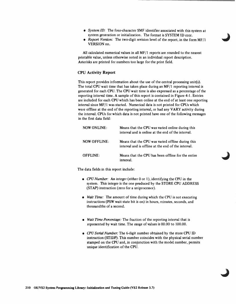
• System ID: The four-character SMF identifier associated with this system at system generation or initialization. The format is SYSTEM ID cccc .
• Report Version: The two-digit revision level of the report, in the form MF/I VERSION nn.
All calculated numerical values in all MF II reports are rounded to the nearest printable value, unless otherwise noted in an individual report description. Asterisks are printed for numbers too large for the print field.
CPU Activity Report
This report provides infonnation about the use of the central processing unit(s). The total CPU wait time that has taken place during an MF/I reporting interval is generated for each CPU. The CPU wait time is also expressed as a percentage of the reporting interval time. A sample of this report is contained in Figure 4-1. Entries are included for each CPU which has been online at the end of at least one reporting interval since MF /1 was started. Numerical data is not printed for CPUs which were offline at the end of the reporting interval, or had any VARY activity during the interval. CPUs for which data is not printed have one of the following messages in the first data field:
NOW ONLINE:
NOW OFFLINE:
OFFLINE:
Means that the CPU was varied online during this interval and is online at the end of the interval.
Means that the CPU was varied offline during this interval and is offline at the end of the interval.
Means that the CPU has been offline for the entire interval.
The data fields in this report include:
• CPU Number: An ,integer (either a or I), identifying the CPU in the system. This integel' is the one produced by the STORE CPU ADDRESS (ST AP) instruction (zero for a uniprocessor).
• Wait Time: The amount of time during which the CPU is not executing instructions (PSW wait state bit is on) in hours, minutes, seconds, and thousandths of a second.
• Wait Time Percentage: The fraction of the reporting interval that is represented by wait time. The range of values is 00.00 to 100.00.
• CPU Serial Number: The 6-digit number obtained by the store CPU ID instruction (STIDP). This number coincides with the physical serial number stamped on the CPU and, in conjunction with the model number, pennits unique identification of the CPU.
210 OS!VS2 System Programming Library: Initialization and Tuning Guide (VS2 Release 3.7)
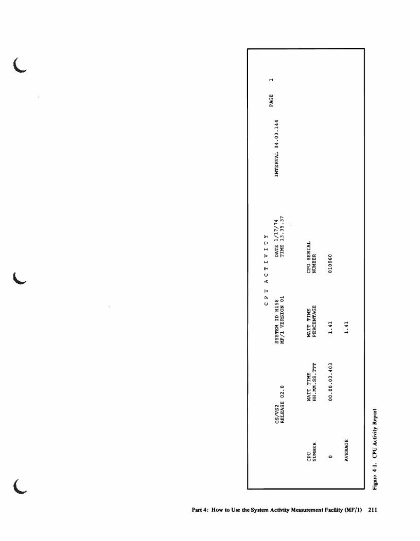
."
~ ~
::c ~ g ~ ~
~ <D til '<
~ > '" ~. ~ ~
~ ~ <D ::I ... '!l
~ ~
i .!!. -'-' N -
r
CPU NUMBER
o
AVERAGE
OS/VS2 RELEASE 02.0
WAIT TIME HH.MM.SS.TTT
00.00.03.403
Figure 4·1. CPU Activity Report
r
CPU ACT I V I T Y
SYSTEM ID HlS8 MF /1 VERSION 01
WAIT TIME PERCENTAGE
1.41
1.41
DATE 1/17/74 TIME 13.35.37
CPU SERIAL NUMBER
010060
r
PAGE 1 INTERVAL 04.00.144

Channel Activity Report
This report provides information about channel loading for all channels in the system. Channel entries are included for each channel in the system which has been online at least one observation cycle since MF /1 was started. Data is not formatted for channels which were oft1ine at the end of the reporting interval, or had any VARY activity during the interval. Channels for which data is not printed have one of the following messages in the first data field:
NOW ONLINE:
NOW OFFLINE:
OFFLINE:
Means that the channel was varied online during this interval and was online at the end of the interval.
Means that the channel was varied oft1ine during this interval and was oft1ine at the end of the interval.
Means that the channel has been offline for the entire interval.
Figure 4-2 contains a sample channel activity report. The data fields in this report include:
• CPU Number: An integer (either 0 or 1), identifying the subject CPU by internal address.
• Channel Number and Type: The channel number is the hexadecimal representation of the external channel address. Channel types are identified as BYTE MPX, SELECTOR, or BLOCK MPX for byte multiplexor, selector, and block multiplexor, respectively.
• Channel Activity Count: The number of successful Start I/Os issued to the channel during the report interval. "Sense" Start I/Os are not counted; however, redundant, successful Start I/O Fast Release instructions (condition code zero) are counted. Six significant digits are printed. A scale factor of M (millions) may be printed after the number. The range is zero to 999,999M.
212 OS/VS2 System Programming Library: Initialization and Tuning Guide (VS2 Release 3.7)

L
• Percent Channel Busy: The percentage of time during the report interval in which the channel was busy. The percentage is derived by dividing the number of sampling observations during the reporting interval in which the channel was busy, by the total number of observations during the reporting interval. An observation is made at periods determined by the CYCLE keyword. The accuracy obtainable for "percent channel busy" is dependent upon the number of observations made (see discussion under "INTERVAL and CYCLE Parameters" above). A channel is considered busy if operating in burst mode at a sampling observation. Percent channel busy values are not produced for byte multiplexor channels.
• Percent Channel Busy and CPU Waiting: The percentage of time during the reporting interval during which the channel was busy and, Simultaneously, the CPU was in the wait state. (The CPU waiting portion of this reported value does not include the execution of the MF /1 sampling routine .). This value is used as a measure of I/O boundedness, and is calculated by dividing the number of observations during the reporting interval in which the channel was in burst mode (condition code 2 from a test channel instruction) and the CPU was simultaneously in the wait state, by the total number of observations during the reporting interval. An observation is made at periods determined by the CYCLE keyword. The accuracy obtainable for "percent channel busy and CPU waiting" is dependent upon the number of observations made (see discussion under "INTERVAL and CYCLE Parameters" above).
This value is not produced for byte multiplexor channels.
The sample channel activity report also shows the standard heading CYCLE, which indicates the requested time between sampling observations. This is the value specified by the CYCLE keyword. The range of values is 0.050 to 0.999 seconds.
Part 4: How to Use the System Activity Measurement Facility (MF/l) 213

~ ... "" i ~ ~
CI.l '<
~
f S"
OQ
t"" 6'
~ ;;:;: i: N"
'" g" ::I
i ;j ::I S"
OQ
~ ~ ~ ~
~ '" ~ ..... ~
OS!VS2 RELEASE 02.0
CHANNEL NUMBER
CPU AND TYPE
o 0 BYTE MPX 1 BLOCK MPX 2 BLOCK MPX 3 BLOCK MPX
TOTAL
Figure 4·2. Channel Activity Report
CHANNEL ACTIVITY COUNT
4 74
NOW ONLINE NOW OFFLINE
78
C HAN N E LAC T I V I T Y
SYSTEM ID DE26 DATE 12/26/73 MF/l VERSION 01 TIME 12.08.46
PERCENT CHANNEL BUSY
3.32
PERCENT CHAN BUSY & CPU WAIT
2.49
D IRE C T A C C E S S D E V ICE ACT I V I T Y
DEVICE ADDRESS
130 150 152 153
230 231
TOTAL
OS!VS2 RELEASE 02.0
VOLUME SERIAL
KBD044 SPooLl SG2003 SG9001
Figure 4-3. Direct Access Device Activity Report
~
DEVICE ACTIVITY COUNT
0 15 26 18
OFFLINE OFFLINE
59
SYSTEM ID DE26 MF /1 VERSION 01
PERCENT BUSY
0.00 0.83 4.17 2.50
DATE 12/26/73 TIME 12.07.46
AVERAGE QLENGTH
0.00 0.00 0.01 0.00
'"
INTERVAL 01.00.050 CYCLE 0.250 SECONDS
INTERVAL 00.59.976 CYCLE 0.250 SECONDS
PAGE
PAGE
1
1
~

I/O Device Activity Reports
The reports provide infonnation about I/O device loading for all devices in the device classes selected by device class keywords. In addition to device activity measures, the report contains a measure of contention delay which is tabulated by device, but may be caused by hardware contention for any unit (channel, control unit, or device) in the path to the device. Device entries are included for each device which has been online at least once since MF/l was started. Data is not fonnatted for devices which were offline at the end of the reporting interval, or had any VARY activity or dynamic device reconfiguration during the interval. Devices for which data is not printed have one of the following messages in the first data field:
NOW ONLINE:
NOW OFFLINE:
OFFLINE:
Means that the device was varied online during this interval and was online at the end of the interval.
Means that the device was varied offline during this interval and was offline at the end of the interval.
Means that the device has been offline for the entire interval.
Note: MF/l sampling overhead is directly related to the number of devices in the device classes being monitored, whether online or not. For example, if an installation is interested in monitoring only tape devices, and specifies 'NODASD', then a large number of direct access devices does not increase MF /1 sampling overhead.
Figure 4-3 contains a sample I/O device activity report (here, the Direct Access Device Report; for the 2305 Fixed Head Storage Device, multiple device entries are made and the reported data reflects each device exposure). The data fields in the report include:
• Device Address: The unique three character hexadecimal device address which identifies a physical I/O device.
• Volume Serial Number: The six character volume serial number of the volume mounted on the device at the end of the reporting interval. This field appears only in reports for direct access and magnetic tape devices.
• Device A ctivity Count: The number of successful Start I/Os issued to the device during the report interval. "Sense" Start I/Os are not counted; however, redundant, successful (condition code zero) Start I/O Fast Release instructions are counted.
• Percent Busy: The percentage of time during the report interval in which the device was busy. The percentage is derived by dividing the number of observations during the reporting interval in which the device was busy. by the total number of observations during the reporting interval. Observations are made at periods determined by the CYCLE keyword. The accuracy obtainable for "percent busy" is dependent upon the number of observations made (see discussion under "INTERVAL and CYCLE Parameters" above).
Part 4: How to Use the System Activity Measurement Facility (MF/l) 215

• Average Queue Length: The average number of requests which are enqueued and waiting to be serviced on the subject device at any given time. This value is a measure of contention at any of the hardware units (channel, control unit, or device) in the path to the device. It is calculated by dividing the accumulation of the requests enqueued against this device at CYCLE observations, by the total number of observations made during the report interval. The accuracy obtainable for "average queue length" is dependent upon the number of observations made (see discussion under "INTERVAL and CYCLE Parameters" above).
The sample I/O device activity report also shows the standard heading CYCLE, which indicates the requested time between sampling observations. This is the value specified by the CYCLE keyword. The range of values is 0.050 to 0.999 seconds.
Paging Activity Report
This report provides detailed information about the demands made on the system paging facilities and the utilization of real and auxiliary storage during the reporting interval. Figure 44 contains a sample paging activity report. Explanations of the fields appearing in the report are as follows:
Main Storage Paging Rates
• Pageable System Areas: These are areas of main storage not associated with a single address space. They include the page able link pack area, the link pack area directory, the link pack area extension, the pageable BLDL list, and the common storage area. Virtual I/O and non-virtual I/O paging rates are provided for these areas, though the Virtual I/O counts for these areas will always be zero in MVS. (In MVS, Virtual I/O is applicable only to address spaces.)
• Address Spaces: These are areas of main storage associated with individual address spaces. Virtual I/O and non-virtual I/O paging rates are provided for these areas.
• Page Reclaim Rate: This is the per-second rate of page frames that are disconnected (stolen) from an address space or the system page able area, but are retrieved for reuse before being re-allocated. The reclaim rate shows the number of non-initial-reference page faults or logical GETs which do not require reading from auxiliary storage. The range ofvalues is 0.00 to 999,999.
• Page Reclaim Percentage: The percentage of the total system reclaim rate for each part of the total.
• Swap Page-in Rate: The per-second rate of pages read into real storage, as a result of address space swap-ins.
• Non-swap Page-in Rate: The per-second rate of pages read into real storage, exclusive of address space swap-ins.
• Total Page-in Rate: The per-second rate of total pages read into real storage. This rate is the sum of swap and non-swap page-in rates.
216 OS/VS2 System Programming Library: Initialization and Tuning Guide (VS2 Release 3.7)

L
• Total Page-in Percentage: The percentage of the total system page-in rate, for each part of the total.
• Swap Page-out Rate: The per-second rate of pages written to auxiliary storage as a result of address space swap-outs.
• Non-swap Page-out Rate: The per-second rate of paging out of real storage, exclusive of address space swap-outs.
• Total Page-out Rate: The per-second rate of total pages written to auxiliary storage. This is the sum of the non-swap and swap page-out rates.
• Total Page-out Percentages: The percentage of the total page-out rate for each part of the total.
The ranges for all the above rates are from 0.00 to 999,999 and are expressed as an average rate for the interval. Explanations of the meanings of the various swapping sub-categories follow:
• Non- VIO Page-in: A page transfer from auxiliary to real storage which occurs as a result of a page fault, PGLOAD, or PGFIX, except those for pages of VIO data sets. Note that if there are concurrent requests for the same page, the first generates a page-in, and all the rest are considered reclaims.
• Non- VIO Page-out: A page transfer from real to auxiliary storage that occurs as a result of a PGOUT (including page stealing and other RSM generated page-outs), for pages other than those of a VIO data set.
• Non- VIO Reclaim: A request for a page as a result of a page fault, PGLOAD or PGFIX, which is satisfied without starting a new page-in, except those recovered by explicit VIO reclaim.
• VIO Page-in: The transfer of a VIO data set page from auxiliary to real storage, resulting from a page fault or a PGLOAD on a VIO window. VIO pages which are swapped in are not included.
• VIO Page-out: A transfer from real to auxiliary storage of a VIO data set page as a result of a PGOUT (including stealing and other RSM generated page-outs) on a VIO window page. VIO pages transferred as a result of a swap-out are not included.
• VIO Reclaim: A VIO request for a real storage data set page which was satisfied without page-in by means of the explicit VlO reclaim interface.
Auxiliary Storage User Pool
The user pool is one of three pools of paging data sets that comprise the total paging space. The other two pools are the system pool and the duplex pool. The duplex pool contains a copy of the system pool.
The following values are snapshots of the end of the measurement interval. These values are probably different from the average during the interval. In particular, the swap-in of the MF /1 address space will decrease the number of unused frames.
Part 4: How to Use the System Activity Measurement Facility (MF/l) 217

• Page Slots: The heading of auxiliary storage page slots for each category. Its values consist of snapshots observed at the end of the measurement interval. The range of values is from 0 to 99,999,999.
• Available Slots: The number of page slots that do not contain any data pages and that are available for use. (When the auxiliary storage user pool contains overflow from the system pool of paging data sets, the count of available slots will be higher than the actual number of available slots.)
• VIO Slots: The number of auxiliary storage page slots that contain pages for VIO data sets.
• Non-VIO Slots: The number of auxiliary storage page slots in the user pool that contain pages that belong to address-space virtual storage.
• Unavailable Slots: The number of auxiliary storage page slots that do not contain any data pages, and not available for use because of permanent I/O errors.
• Total Slots: The sum of all auxiliary storage page slots in the user pool of paging data sets.
• Percent Page Slots: The percent of total auxiliary page slots in each category.
Pageable Main Storage Counts
The following values are snapshots at the end of the measurement interval. These values are probably different from the average during the interval. In particular, the swap-in of the MF/l address space will decrease the number of unused frames.
• Unused Frames: The number of pageable real storage frames not allocated to any address space, or to the pageable system area.
• Data Pages: The number of pageable real storage frames allocated to swapped in address spaces, common area, or dynamic SQA.
• Total Frames: The sum of all real storage frames in the system.
• Page Frames: The number of real storage frames in each category. It is observed at the end of the measurement interval. The range of values is o to 4,096.
• Percent Page Frames: The percent of total real storage frames in each category.
Swap Counts
• Swaps: The number of address space swap sequences, where a swap sequence consists of an address space swap out and swap in. The range of values is o to 9,999,999.
• A verage Pages per Swap-out: The average number of pages swapped in for each address space swap in. The range of values is 0 to 4,096.
• A verage Pages per Swap-in: The average n umber of pages swapped in for each address space swap in. The range of values is 0 to 4,096.
21~ OS/VS2 System Programming Library: Initialization and Tuning Guide (VS2 Release 3.7)

"1::1
~ ~
::c ~ S c:: ~ :; (I>
CZl '<
~ ~ ~.
~ 3: g
I ".!j
Pl =: ~ i ~ -'-' I-.» -\Q
r
OS/VS2 RELEASE 02.0
CATEGORY
PAGEABLE SYSTEM AREAS
VIO
NON VIO
SUM
ADDRESS SPACES VIO
NON VIO
SUM
TOTAL SYSTEM VIO
NON VIO
SUM
PAGE RECLAIMS
RATE
0.00
1. 83
1. 83
0.06
1.01
1.07
0.06
2.84
2.89
PERCENT OF TOTAL SUM
0
63
63
2
35
37
2
98
100
AUXILIARY STORAGE USER POOL
PAGE SLOTS
AVAILABLE SLOTS 14,321
VIO SLOTS 7
NON-VIO SLOTS 1,100
UNAVAILABLE SLOTS 0 ---------
TOTAL SLOTS 15,428
Figure 44. Paging Activity Report
r P A GIN G ACT I V I T Y
SYSTEM ID JA11 MF/1 VERSION 01
DATE 1/11/74 TIME 16.25.08
MAIN STORAGE PAGING RATES PER SECOND
PAGE IN
SWAP NON SWAP
TOTAL RATE
PERCENT OF TOTAL SUM SWAP
0.00 0.00 0
8.48 8.48 62
8.48 8.48 62
1. 71 1.71 12
0.13 3.37 3.49 26 0.02
0.13 5.08 5.20 38 0.02
1.71 1.71 12
0.13 11. 85 11.98 88 0.02
0.13 13 .56 13.68 100 0.02
PAGEABLE MAIN STORAGE COUNTS --------------------------------
PAGE PERCENT FRAMES PERCENT
93 UNUSED FRAMES 145 50
0 DATA PAGES 145 50
7 TOTAL FRAMES 290 100
0
100
INTERVAL 15.00.459
PAGE OUT
NON SWAP
0.00
0.79
0.79
2.19
4.01
6.19
2.19
4.80
6.99
TOTAL RATE
0.00
0.79
0.79
2.19
4.03
6.22
2.19
4.82
7.01
SWAP COUNTS
PAGE 1
PERCENT OF TOTAL SUM
0
11
11
31
57
89
31
69
100
---------------------
SWAPS 6
AVERAGE PAGES PER 3 SWAP OUT
AVERAGE PAGES PER 19 SWAP IN
r

Workload Activity Report
This report provides information about the system workload activity, and its relationship to the installation-specified performance objective for each performance group period. This information can be used to evaluate and modify the installation performance specification (IPS). The report may be produced in anyone of three different levels of detail, specified by the parameters indicated below from the most detailed report to the least detailed report:
Performance group period level:
Performance group level:
System summary report:
WKLD(PERIOD)
WKLD(GROUP)
WK LD(SYSTEM)
The performance group period report is the most detailed workload activity report provided. It prints workload information broken down by performance group period - that is, information is provided for transactions associated with each performance group period defined in the IPS. The performance group report provides an intermediate level of detail. It provides information for all transactions associated with each performance group defined in the IPS. The system summary report is the least detailed report provided. It provides information applicable to the system as a whole during the measurement interval.
The workload activity report fields provide two sets of information at each report level:
• Active Transactions: Information on active transactions includes only data for transactions that were active during the reported MF/l interval. There are four fields: Service in Interval; Average Transaction Service Rate; Workload Level; Average Transactions.
• Ended Transactions: Information on ended transactions includes data for transactions that may have been active in previous MF/1 intervals and for only part of the currently reported interval. Ended transactions include two fields: Ended Transactions and Average Time of Ended Transactions.
Figure 4-5 contains a sample workload activity report, at the performance group period level. Explanations of the fields appearing in the report follow:
• Performance Group Number: (This is prOvided in the performance group and performance group period level reports only.) - The identification of the installation defined performance group which defines the prescribed treatment for a class of users. The range of values is 1 to 255.
• Performance Group Period: (This is provided in the performance group period level report only.) - A number identifying an identifiable portion of the life of a transaction, which the installation has singled out to be associated with a particular performance objective. The range of values is 1 to 8.
• Service in Interval: The total number of service units absorbed by transactions during the measurement interval. The range of values is 0 to 240 . Only 7 significant digits are printed in the report. Higher values are shown as millions of service units by an M follOWing the number.
• A verage Transaction Service Rate: The total number of service units absorbed by all transactions in the period, group, or system, divided by the active time of all transactions. The entire "transaction active" time is equal to the total transaction active time accumulated by all associated transactions. Each
220 OS!VS2 System Programming Library: Initialization and Tuning Guide (VS2 Release 3.7)

transaction's "transaction active" time is equal to the total time during which the transaction was in real storage, added to any swapped-out time during which the transaction was not in a "wait" state. It does not include time between job steps, for batch transactions. Notice that the service rate provided to all transactions (in the period, group, or system) is equal to the "average transaction service rate" times the "average transactions". The range of values is 0 to 10 13 minus one. Only 6 significant digits are printed. Higher values are shown as millions of service units per second, by an M following the number. (This value is not rounded; it is truncated.)
• Workload Level: The level in the IPS at which associated performance objectives are being satisfied. The level indicated for each performance group period is the normalized level for all transactions in that period. The levels given for the performance group and the system total are averages of the "period" workload levels weighted by accumulated service. The range of values is 1.00 to 224.00. The label EST is shown after the value for estimated values. An estimated value is given where the same service rate is specified in the IPS for more than one workload level - that is, when the performance objective is horizontally graphed. Note that the "system total" workload level as printed by MF/1 is not necessarily identical to the system workload level as seen by SRM.
• Average Transactions: The average number of transactions simultaneously active in the measurement interval. It is the quotient of the total active time spent by all transactions (in the performance group period/performance group/system) divided by the measurement interval time. The range of values is 0.00 to 224. Only 6 Significant digits are printed. Higher values are shown as millions of transactions by an M following the number.
• Ended Transactions: The total number of transactions which terminated during the measurement interval. The range of values is 0 to 240 . Only 6 significant digits are printed. Higher values are shown as millions of transactions by an M following the number.
• Average Time of Ended Transactions: The average transaction elapsed time of all transactions which terminated during the measurement interval. A transaction's "transaction elapsed" time is the real time interval between the start and end of the transaction. The maximum number of hours is 999.
The standard report heading appears with one additional heading:
IPS ID: This is the member of SYS1.PARMLIB that contains the controlling IPS (i.e., IEAIPSxx).
Data values in this report are not printed for performance groups or performance group periods which would have all values equal to zero. The word ZEROS is printed in the first field following the performance group or performance group period number.
The workload activity report may be a "short" report (it may not cover the entire reporting interval) if the Workload Manager of the SRM stopped collecting statistics as a result of a change in the IPS during the report interval. If this is the case, the INTERVAL field of the header contains the time interval during which statistics were being collected.
Part 4: How to Use the System Activity Measurement Facility (MF/l) 221

N N N
i WORKLOAD ACT I V I T Y --~ PAGE 1
N OS/VS2 SYSTEM ID JA25 DATE 1/25/74 INTERVAL 04.00.170
til RELEASE 02.0 MF/l VERSION 01 TIME 19.42.39 IEAIPST2 '< ~ '" 3 PERFORM PERFORM SERVICE AVERAGE AVERAGE ENDED AVERAGE TIME OF "0 GROUP GROUP IN TRANS. WORKLOAD TRANS- TRANS- ENDED TRANS.
~ NUMBER PERIOD INTERVAL SRV RATE LEVEL ACTIONS ACTIONS HHH.MM.SS.TTT
3 3 001 1 118 0 50.00 EST 1.00 0 000.00.00.000 ~.
r- 001 ALL 118 0 50.00 1.00 0 000.00.00.000 5' ... ~ 002 - 018 ZEROS
i. e: 121 1 102 7 38.64 0.05 8 000.00.01. 624 N' .. 2 - 3 ZEROS ... o· 121 ALL 102 7 38.64 0.05 8 000.00.01.624 ::s .. ::s Q. ..., 122 1 98 7 38.64 0.06 8 000.00.01.748 c 2 - 3 ZEROS ::s ~.
122 ALL 98 ~
7 38.64 0.06 8 000.00.01. 748
8: '" 123 1 95 9 38.25 0.04 8 000.00.01. 220 '< 2 - 3 ZEROS til N
::c 123 ALL 95 9 38.25 0.04 8 000.00.01. 220
'" i ~ 124 1 96 9 38.25 0.04 8 000.00.01. 287 ... 2 - 3 ZEROS :... '-'
124 ALL 96 9 38.25 0.04 8 000.00.01.287
125 1 70 8 38.44 0.03 3 000.00.02.721 2 - 3 ZEROS
125 ALL 70 8 38.44 0.03 3 000.00.02.721
Figure 4-5. Workload Activity Report (Part I of 2)
\, " ~

"!i
~ "" = ~ S"
i ~ t:Il '<
i ;lo-n ~.
~ iii::
I !: -"fl ~ ~
i .:::! -'-' N N ....
r r
WORKLOAD ACTIVITY
OS/VS2 SYSTEM ID JA25 DATE 1/25/74 RELEASE 02.0 MF/l VERSION 01 TIME 19.42.39
PERFORM PERFORM SERVICE AVERAGE AVERAGE GROUP GROUP IN TRANS. WORKLOAD TRANS-NUMBER PERIOD INTERVAL SRV RATE LEVEL ACTIONS
126 1 68 8 38.44 0.03 2 - 3 ZEROS
126 ALL 68 8 38.44 0.03
127 1 63 7 38.64 0.03 2 - 3 ZEROS
127 ALL 63 7 38.64 0.03
128 1 56 17 36.69 0.01 2 - 3 ZEROS
128 ALL 56 17 36.69 0.01
SYSTEM TOTAL 766 2 40.11 1. 31
Figure 4·5. Workload ~ctivity Report (Part 2 of 2)
r
PAGE 2 INTERVAL 04.00.170 IEAIPST2
ENDED AVERAGE TIME OF TRANS- ENDED TRANS. ACTIONS HHH.MM.SS.TTT
3 000.00.02.750
3 000.00.02.750
3 000.00.02.656
3 000.00.02.656
3 000.00.01. 083
3 000.00.01.083
44 000.00.01. 697

Using MF/l
The uses to which MF /1 can be put are dependent upon the needs and goals of the individual installation. The follOWing sections indicate hypothetical examples of use of each of the MF /1 report types. The examples are not meant to reflect actual figures or relationships, but rather to indicate the possibilities for tuning that MF /1 can provide. The indicated methods of analysis are not the only ones, and are not necessarily the best ones, but are suggestive of the possibilities that MF /1 provides.
Using the CPU Activity Report
An installation wishing to monitor its CPU utilization during the afternoon hours of 1 :00 to 3 :00 (its peak period) requests the collection of CPU usage data by having the operator enter the follOWing command at 1 :00 P.M.
START MF1.EXAMPLE" ,(NOPAGING,NOCHAN,NOWKLD, NODEVICE, INTERVAL(30M), STOP(2H))
Assuming that the installation is running with the IBM-supplied MF /1 cataloged procedure and the IBM-supplied IRBMF100 parmlib member, the following options will control the MF /1 execution:
CPU NOCHAN NODEVICE NOPAGING NOWKLD CYCLE(250) INTERVAL (30M) MEMBER (00) OPTIONS NORECORD REPORT(DEFER) STOP(2H) SYSOUT(A)
The CYCLE Parameter will have no effect upon execution, since neither channel nor device statistics are being gathered.
This list of options will result in 4 CPU activity reports being printed after MF /1 termination, based upon statistics gathered each half-hour for two hours.
The installation finds, from averaging CPU wait time percentages, that the CPU is in the wait state 30% of the time during this peak period. Determining that this is unacceptable, the installation creates a new PARMLIB member IEAOPTxx and specifies the CPU resource factor coefficient (RFC) in this new member as:
CPU = 9.9
Since previously the value of this coefficient was equal to 1.0, the installation reasons that this change will cause the SRM to weight CPU imbalances more heavily in making swapping decisions. The installation places the new member into
224 OS/VS2 System Programming Library: Initialization and Tuning Guide (VS2 Release 3.7)

operation, and observes the effect upon the system by requesting a full complement ofMF/1 reports for a subseuqent 1 :00 to 3:00 peak period. To obtain these reports, the operator enters:
START MF1.EXAMPLE" ,(lNTERVAL(30M),STOP(2H))
This execution produces 4 reports each of CPU, channel, device, paging, and workload activity. Analyzing the CPU activity report, the installation finds that CPU utilization has been raised to 100%. However, analyzing the workload activity report (see Workload Activity Report, below), the installation finds that the service rate provided to a high priority group of users has been seriously degraded. The installation makes the inference that this resulted from the RFC change. Therefore, the installation decreases the CPU resource factor coefficient as follows:
CPU = 5.0
After placing the modified IEAOPTxx member into operation and monitoring during a subsequent peak period, the installation finds that the service rate provided to the high priority performance group is at an acceptable level. Furthermore the CPU utilization, though not so high as at the last monitoring, is still substantially above the original level.
Using the Channel Activity Report
An installation wishes to analyze the utilization of its I/O channels. It decides to try to obtain about 2400 samples as a basis for the printed figures in each printed channel report. To achieve this number of samples in each printed report, a CYCLE value of 500 milliseconds is chosen (2 samples per second), and a reporting INTERVAL length of 20 minutes (1200 seconds, 2400 samples) is selected. (See discussion under "Interval and Cycle Parameters", above.) The system operator enters the following command to initiate MF/I operation, at four different periods during the day:
START MF1.EXAMPLE" ,(NOCPU,NOPAGING,NOWKLD, NODEVICE, INTERVAL(20M),CYCLE(500),STOP(1 H)
Assuming that the installation is running with the IBM-supplied MF /1 cataloged procedure and IRBMFIOO parmlib member, the following options will control the MF/I operation:
NOCPU CHAN NODEVICE NOPAGING NOWKLD CYCLE(500) INTERVAL(20M) MEMBER(OO) OPTION NORECORD REPORT(DEFER) STOP(1 H) SYSOUT(A)
Part 4: How to Use the System Activity Measurement Facility (MF/l) 225
This list of options will result in three channel activity reports being printed after MF/l termination, based upon statistics gathered every twenty minutes for one hour.
The installation finds, in comparing the percent channel busy indications from each channel, during each of the four one-hour periods of MF /1 activity, that one particular channel (channel 2) has a continually significantly higher percent channel busy figure than the other channels. The installation attempts to correct this situation by increasing the value of the I/O resource factor coefficient in the parmlib system tuning parameters member (parmlib member IEAOPTxx) as follows:
10C = 5.0 (previously, the value was 1.0).
After an IPL with the modified IEAOPTxx member, the installation monitors the effect of the change upon the system by again requesting that the operator enter the previous command four times during the day, each time obtaining three printed channel activity reports.
Again, the installation finds that the utilization of channel 2 is too high. This indicates that the SRM has been unable to improve the imbalance by its swapping recommendations. To investigate the problem further, the installation requests device activity reports, as explained below.
Using the Device Activity Report
In pursuing the problem outlined under "Channel Activity Report" the installation .'\ notes that both tape and direct access devices are connected to channel 2. There- ..", fore, the installation requests that the operator enter the following START MF/l command a number of times, to analyze the device activity on this channel:
START MF1.EXAMPLE" ,(NOCPU,NOCHAN,DEVICE(NOUNITR, NOCOMM,NOGRAPH,NOCHRDR) NOPAGING,NOWKLD, INTERVAL(20M),CYCLE(500),STOP (1H))
226 OS/VS2 System Programming Library: Initialization and Tuning Guide (VS2 Release 3.7)

L
Assuming IBM supplied MF/I cataloged procedure and IRBMFIOO parmlib member, the following options will control the MF/I operation:
NOCPU NOCHAN DEVICE (NOCH RD R,NOCOMM,DASD,NOG RAPH,T APE,NOUN ITR) NOPAGING NOWKLD CYCLE(500) INTERVAL (20M) MEMBER (00) OPTION NORECORD REPORT (DEFER) STOP(1 H) SYSOUT (A)
This list of options will result in three tape device activity and three direct access device activity reports being printed after MF/I termination, based upon statistics gathered every twenty minutes for I hour.
The installation finds that two of the direct access devices on channel 2 both have high percent busy figures, and high average queue length figures. The installation checks the volumes indicated as mounted on these devices, and finds several frequently used system data sets on each. After relocating some of these data sets, subsequent MF / I analysis shows a better balance of I/O device and channel utilization.
Using the Paging Activity Report
This report provides a wide breadth of information not susceptible to simple interpretation. An installation could use 'it, for example, to analyze the amount of swapping overhead that is occurring. It could also analyze the change to this over· head that is produced when certain System Resources Manager parameters are varied (for example, the interval service value (ISV) in the IPS). The installation might similarly wish to analyze the percentage of auxiliary storage slots that are unused, in view of the relation of this percentage to the efficiency of operation of the Auxiliary Storage Manager. (A low percentage of unused slots could result in an excessive amount of ASM overhead, in trying to access these unused slots.) Alternatively, the installation might wish to compare paging rates indicated by this report with the profile of user activity provided by the Workload Activity Report, to analyze possible correlations between high paging rates and high percentages of active users from certain performance groups.
Part 4: How to Use the System Activity Measurement Facility (MFj 1) 227

Using the Workload Activity Report
This report, like the paging report, is susceptible to a wide range of uses. Some examples follow:
• The system workload level is the figure appearing in the "system total" row, under the workload level heading. It is a measure of the contention for system resources during the reporting interval. Analysis of the system workload level at different times of the day can provide the installation with an idea of the response times that users associated with different performance groups can expect at different times. With performance groups defined as follows:
PGN = 30,(OBJ = 24)
PGN = 32,(OBJ = 23, DUR = 10K) (OBJ = 22, DUR = 10K) (OBJ = 21)
and performance objectives as depicted in Figure 4-6, the illustrated range of system workload levels can be expected to have a great effect on users associated with performance group 32, and little if any effect on users associated with performance group 30. This is because the service rate drops off drastically in the indicated range for performance objectives 21,22, and 23 (those associated with performance group 32), while remaining fairly constant for performance objective 24 (associated with performance group 30).
• The distribution of transactions among performance groups is found under the column labeled "average transactions" and in the row labeled "ALL" in the performance group period column. The distribution can give a general profile of the system workload at different times of the day. In contrast, the distribution of total service among performance groups (found under the "service in interval" column, and in the row labeled "ALL" in the performance group period column) can tell the installation which performance groups are really getting the bulk of the system resources.
• The total service provided to all users in the measurement interval is found under the "service in interval" column and in the "system total" row. This information can provide a basis for comparing system throughput under different workload conditions. By comparing this figure for similar MF/l reporting interval lengths, the installation can determine whether changes made to improve the system configuration have had the desired effect' on throughput.
228 OS/VS2 System Programming Library: Initialization and Tuning Guide (VS2 Release 3.7)
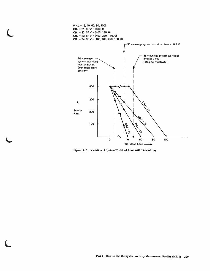
WKL = (2,40,60,80, 100) OBJ = 21, SRV = (400, 0)
OBJ = 22, SRV = (400, 150,0) OBJ = 23, SRV = (400, 220, 110,0) OBJ = 24, SR V = (400, 400, 250, 130, 0)
10=average ~ system workload level at 6 A.M. (minimum daily . activity)
t Service Rate
400
300
200
100
2
I I I
r 30 = average system workload level at 5 P.M.
(
48 = average system workload I level at 3 P.M. I (peak daily activity)
I I I
40 60 80 100
Workload Level ~
Figure 4- 6. Variation of System Workload Level with Time of Day
Part 4: How to Use the System Activity Measurement Facility (MFj 1) 229
230 OS/VS2 System Programming Libruy: InitiaIization and Tuning Guide (VS2 Release 3.7)

L
Part 5: System Performance Factors
Part 5 contains discussions of factors that affect system performance and discussions of certain tools that can measure performance. Each discussion includes guidelines, and rationale. Some discussions also include questions and answers. Since MVS is significantly different from MVT, the discussions emphasize new aspects of the system, such as VIO, VSAM catalog, and the page able link pack area. The performance information is based on design analysis; that is, on projections of how the system is supposed to work. Some of these ideas will change as system experience is gained. These new insights, based on system measurements, will first appear in Installation Newsletters as tuning guidelines.
The following performance topics are included in Part 5, in this order:
• Guidelines for the Effective Use of Paging Data Sets • The Page able Link Pack Area: Its Advantages and Uses • VIO Performance • Device Allocation Performance • VSAM Catalog Performance • How SMF Can Supplement MF/l • The Use of GTF to Track Sysevents • TCAM Tuning Considerations • TSO and Batch Service Trade-offs Via the IPS • Miscellaneous Performance Guidelines
Guidelines for the Effective Use of Paging Data Sets
Note: Additional information on this subject appears under the PAGE parameter of parrnlib member IEASYSxx and in the performance topic, "The Pageable Link Pack Area: Its Advantages and Uses".
The following recommendations should probably improve system performance through the careful use of paging data sets and devices:
• If you place multiple paging data sets on moveable-head devices (e.g., 3330s), try to avoid placing more than one paging data set on any single moveablehead device. The purpose of this advice is to reduce contention among multiple data sets for the use of the moveable head device.
Reason: When Auxiliary Storage Manager (ASM) starts I/O requests for a paging data set, it starts only the number of requests that can complete within a service burst, currently set to 50 milliseconds. If there are multiple paging data sets on the same device, contention for the use of the device is more likely, compared with one paging data set per device. Consequently, ASM adjusts the length of time (the service burst) allowed for completing a request. Therefore, the request will take longer than expected and fewer requests will be started the next time. Of course, you can experiment with multiple page
Part 5: System Performance Factors 231

Paging Data Sets (continued)
data sets per device, and check for device contention by running MF/l with typical job streams, to obtain Direct Access Device Activity reports during various time intervals. The MF/l data on device activity count, percent busy, and average queue length should suggest whether device contention is a problem. MF/l data for devices that contain only one data set per device can be used as a comparison base.
You may, however, place low-activity non-paging data sets on the same device that holds a paging data set. ASM will be aware of non-paging data sets on these devices since ASM will detect channel busy, etc. Such sharing increases device efficiency, but contention, if it occurs, will slow up access to the paging data set. You can use MF /1 Direct Access Device Activity report to detect whether device contention is occurring.
• Place most paging data sets on moderate speed devices, such as 3330's, to avoid overloading the fast device(s). You should probably place on the fast device, such as a 2305-2, only one paging data set (the PLPA) plus the primary spooling data set. * (An exception to this exclusive advice may be paging data sets for a large time sharing or teleprocessing installation for which response time is critical. Such uses may require the fastest device obtainable.)
Reason: ASM's list of paging data sets is ordered according to the speed of the devices on which the paging data sets are located: 2305-1,2305-2,3350, 3330-1,3330,3340,3344,2314,2319. ASM starts with the top of the list, but spreads requests across all devices. Because of this ordering, the faster devices on the front of the list would tend to be written on more frequently than the relatively slower devices toward the end of the list. By placing most paging data sets on moderate speed devices, and by allocating sufficient space, you may be able to assure free space on the moderate speed devices and thus counteract ASM's bias toward the faster devices .
• Set up a relatively slow device (e.g., 2314) for the data set that will contain secondary copies of duplexed common areas. (The common areas are the PLPA, the modified link pack area, the common service area, and ASM's address space). You can do this by specifying the data set as the second dsname in the PAGE parameter in IEASYSxx.
ASM duplexes the areas so that it can recover from I/O errors on the primary copy by reading the secondary copy. The secondary-copy data set should be of adequate size to hold all the common areas and should be on a separate slower device and ideally on a separate channel from that which holds the primary copy. Such separation aids error recovery.
Reason: The objective is to concentrate secondary copies on slow-device data sets, if at all possible. The reasoning is that the secondary
*For specific advice on the PLP A data set, see the performance topic entitled "The Page able Link Pack Area: Its Advantages and Use". For suggestions on placement of primary and secondary spooling data, see the topic "JES2 Performance" in OS/VS2 System Programming Library: JES2.
232 OS/VS2 System Programming Library: Initialization and Tuning Guide (VS2 Release 3.7)
Paging Data Sets (continued)
copies are read only a minority of the time for error recovery, and therefore should not occupy space on devices (such as a 2305) that are relatively expensive and which have relatively small capacity.
• Specify a data set to exclusively contain the primary copy ofPLPA. You can do this by specifying the data set as the first dsname in the PAGE parameter in IEASYSxx or as the first dsname in the first DATASET macro at sysgen that contains the PAGEDSN parameter. (The dsname in PAGEDSN, prefixed by SYSl., is placed into IEASYSOO by sysgen.) You should place the PLPA modules on the fastest available device l , since stolen real-storage pages will have to be replaced from the PLPA data set. Avoid placing other paging data sets on the same device, unless you are using a 2305-2 or other fixed-head device. (For additional suggestions on the PLPA, see the topic entitled "The Pageable Link Pack Area: Its Advantages and Use".)
Reason: The PLPA is a high usage data set. It's desirable to speed the access to this data set and to avoid device contention. It may be possible to share the device with other performance-sensitive data sets, such as the primary spool volume (checkpoint records and spool messages queue only)2, provided contention does not develop. You may use the MF/l Direct Access Activity report to check for possible device contention.
• Overspecify space for all page data sets to allow "breathing room". The extra space allows for the creation of additional address spaces before current ones are deleted, and permits some reasonable increase in the number of concurrent VIO data sets. VIO data-set growth may become a problem, since there's no simple way to limit total VIO data sets used by multiple jobs and TSO sessions. The last recourse to get rid of VIO data sets is to re-IPL, specifying CVIO, although this action will prevent warm start forthe jobs that are using VIO data sets. (For additional space considerations, see the guideline for estimating paging space later in this topic.)
• When you obtain a new VSAM data space for paging on a moveable head device, ensure that extents are in ascending TTR order.
Reason: Paging spaces may be allocated such that extents are not in ascending TTR order. The Auxiliary Storage Manager slot sort algorithm is unaware of these extents and their ordering. The slot sort algorithm tries to optimize device arm motion based on the relative block address (RBA) of each request. When extents are not in ascending TTR order, the result can be excessive arm motion and performance degradation.
1 A 2305-2 can hold 2470 4K-sized slots, when 95 cylinders are allocated at 26 slots per cylinder.
2 See "1£S2 Performance" in OS/VS2 System Programming Library: JES2.
Part 5: System Perfonnance Factors 233

Paging Data Sets (continued)
• Avoid using 2314s as paging devices, except to hold secondary copies of duplexed areas.
Reason: There are two reasons. The first is that the device is relatively slow. Secondly, in a heavy paging environment, all paging devices will be used, but the number of requests passed to each device will vary according to the speed of the device, channel usage, etc. A 2314 would be used often but relatively few paging requests would be written to it compared with higher speed devices. Faster devices with little activity other than paging would receive most of the page requests.
• You may estimate the total size of all paging data sets by considering the following space factors (the formula for this calculation is in OS/VS2 System Programming Library: Storage Estimates).
1. The space needed for the common areas of virtual storage (PLP A, MLP A, CSA, and ASM's address space). Double this space estimate, since ASM duplexes the common areas.
2. The space needed for areas of virtual storage that are not duplexed: private areas of concurrent address spaces, and concurrently existing VIO data sets. (The system portion of concurrent address spaces needs to be calculated only once, since it represents the same system modules.)
For the private areas (mentioned in the preceding paragraph), you can possibly simplify the space estimation by picking an arbitrary value that you think is reasonable. Set up this amount of paging space; then run the system with some ,..J typical job loads. Start MF/l while the jobs are running in order to determine the accuracy of your estimate. MF/l's Paging Activity report gives data on the number of unused 4K slots, the number of VIO data set pages and address space pages, the number of unavailable (defective )slots. From this data, you should be able to resize your original space estimate. (See Part 4: How to Use the System Activity Measurement Facility, Paging Activity Report, for additional information. In using MF/l data for this purpose, the user should note that the Auxiliary Storage User Pool portion of the MF/l Paging Activity Report indicates a snapshot of slot usage at the end of the report interval. Slot usage is likely to vary during a report interval.)
Remember that to add more paging space you must use the DEFINE SPACE utility to preformat and catalog each new page data set, and then you must specify the data set at the next IPL by means of the PAGE parameter. (See OS/VS2 Access Method Services for information on the DEFINE SPACE command, and on the related commands, ALTER and DELETE, used for the handling of VSAM data sets. Also see the description of the PAGE parameter in parrnlib member IEASYSxx in the Initialization chapter of this manual.)
234 OS/VS2 System Programming Library: Initialization and Tuning Guide (VS2 Release 3.7)

•
Paging Data Sets (continued)
• ASM "reserves" slots to back each address space (defined here as a TSO terminal, batch address space, or VIO data set) as each address space is created. The total slots available for user address spaces is obtained from total page data sets minus the space required for the common areas of virtual storage. If there are only two page data sets, one data set is used for the common area and user primary spaces; therefore, the number of total user slots is obtained by subtracting the common area space. (Therefore, a minimum of three paging data sets is recommended.) The number of slots to reserve is calculated as follows:
1. For a TSO terminal or batch address space, ASM computes the number of slots needed for mapping the user private area. This value is then divided by the constant ILRSLOTC in the nucleus CSECT ILRSLOTC (currently initialized to four).
2. For a VIO data set, the maximum RPN value specified as part of the ASSIGN request is used for the number of slots required. This value is then divided by the constant ILRSLOTV in the nucleus CSECT ILRSLOTV (currently initialized to four).
As each address space is created, the anticipated number of slots for that address space (the reserve) is subtracted from the available slot count. When there are no longer enough slots remaining, ASM rejects the creation of an address space .
Expressed in terms of cylinders per paging data set, the reserve for each address space can be calculated as follows:
The average size of a private area of 12,000,000 bytes divided by the default constant of 4 equals 3,000,000 bytes of address space. These 3,000,000 bytes are represented by 732 slots which is equivalent to 13.2 cylinders on a 3330 paging device, or 26 cylinders on a 2314 paging device.
Therefore, for each address space created by ASM, the number of cylinders available for paging is reduced by 13.2 for a 3330 or 26 for a 2314.
The constants used to determine this reserve can be modified so that more or fewer slots are subtracted from the number of available slots. For example, if the constant ILRSLOTC is six instead of four, then approximately 2,000,000 bytes of address space would be subtracted from the available slots with the address space assignment. This is roughly 488 slots (8.6 cylinders for a 3330 or 17 cylinders for a 2314). Conversely, the constants (ILRSLOTV for VIO data sets or ILRSLOTC for batch address spaces) could be decreased to reserve more slots.
Error message IEA8901, a 03C wait state, or a system completion code of OEI may indicate that the reserve count has been exhausted.
Part 5: System Performance Factors 235
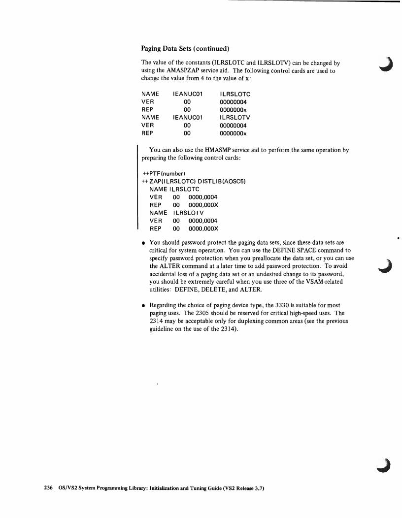
Paging Data Sets (continued)
The value of the constants (ILRSLOTC and ILRSLOTV) can be changed by using the AMASPZAP service aid. The following control cards are used to change the value from 4 to the value of x:
NAME IEANUC01 ILRSLOTC VER 00 00000004 REP 00 OOOOOOOx NAME IEANUC01 ILRSLOTV VER 00 00000004 REP 00 OOOOOOOx
You can also use the HMASMP service aid to perform the same operation by preparing the following control cards:
++PTF (number) ++ ZAP(I LRSLOTC) 0 ISTU B (AOSC5)
NAME ILRSLOTC VER 00 0000,0004 REP 00 OOOO,OOOX NAME ILRSLOTV VER 00 0000,0004 REP 00 OOOO,OOOX
• You should password protect the paging data sets, since these data sets are critical for system operation. You can use the DEFINE SPACE command to specify password protection when you preallocate the data set, or you can use the ALTER command at a later time to add password protection. To avoid accidental loss of a paging data set or an undesired change to its password, you should be extremely careful when you use three of the VSAM-related utilities: DEFINE, DELETE, and ALTER .
• Regarding the choice of paging device type, the 3330 is suitable for most paging uses. The 2305 should be reserved for critical high-speed uses. The 2314 may be acceptable only for duplexing common areas (see the previous guideline on the use of the 2314).
236 OS/VS2 System Programming Library: Initialization and Tuning Guide (VS2 Release 3.7)
•

L
How ASM Handles Paging Read and Write Requests
The following ASM algorithms are briefly described in the hope that they may suggest additional performance gUidelines:
1. ASM allocates one 10MB (I/O request block) for disk, four for 2305 devices. This arrangement allows only one request at a time to disk, but up to four in parallel to 2305 devices.
2. When a paging data set is selected, ASM sorts and processes pending read requests for the data set, inter-mixing write requests on the same cylinders, if it can.
3. ASM next tries to locate empty slots for write requests, if the request quota has not yet been used this time around. ASM keeps bit maps that indicate available free slots. The scan for empty slots starts from the lowest "read" cylinder or, if no reads, starts from the current "edge" of the allocated slots on the paging data set. The scan continues across the data set to the other "edge" until all requests have been assigned slots, if possible. Remaining requests will be processed during the next service burst (currently 50 milliseconds) .
Part 5: System Performance Factors 237

Paging Data Sets (continued)
Questions and Answers
The following ASM questions have been asked by customers.
Q: What happens if there's an unrecoverable I/O e"oron a paging device?
A: If the error occurs during the reading of a common duplexed area, the secondary copy is read. If an I/O error occurs during the reading of a non-duplexed area, the job terminates, an end-of-memory condition is indicated, and all non-shareable devices are freed. If an error is detected on output, the page out is retried. However, since there's no readback check, we may not know if a data error occurred.
Q: Does ASM use I/O load balancing?
A: Yes, it does its own, by keeping a history of the average length of time to read or write one page on each paging data set, then starting more or fewer page requests depending on how fast page requests are being satisfied by the device. By starting only 50 milliseconds' worth of requests to each page space, ASM keeps CCW strings relatively short, and resources are spread among all paging data sets. ASM can react quickly to busy spurts on particular devices or channels and favor those devices or channels that are providing the best service.
Q: How does the auxiliary-storage shortage prevention algorithm in the SRM prevent shortages?
A: By swapping out address spaces that are accumulating paging space at a rapid rate. Page space is not immediately freed, but another job on TSO session (still executing) will complete and free page space eventually. The SRM also prevents the creation of new address spaces and informs the operator of the shortage so that he can optionally cancel a job.
Q: Is running out of auxiliary storage (paging space) catastrophic?
A: After determining what kind of workload placed a heavy demand on paging space (TSO, batch storage, or VIO), it may be possible to modify key ASM constants (ILRSLOTC and ILRSLOTV), prior to re-IPLing with the same page data sets. These constants are described in the topic "Guidelines for the Effective Use of Paging Data Sets" in this chapter. Otherwise, it's necessary to re-IPL to specify an additional pre formatted and cataloged page data set. (See the description of the PAGE parameter of the IEASYSxx member in the Initialization chapter.)
Q: Can we dynamically allocate more paging space?
A: No. It's necessary to re-IPL, but avoid specifying CLPA or CVIO as an IPL parameter. Either parameter will get rid of existing VIO data sets.
238 OS/VS2 System Programming Library: Initialization and Tuning Guide (VS2 Release 3.7)

Paging Data Sets (continued)
Q: How is ASM slot selection being done?
A: ASM first selects a cylinder on a page space, maintaining a circular action of the disk arm from the beginning of the data set to the end, then starting over at the beginning again. ASM remembers where it last left the arm and selects the nearest cylinder beyond the one last processed. When a cylinder has been selected, slots within that cylinder are chosen according to the best rotational position of eligible slots. The same procedure is followed for a 2305 device (reads from low-numbered slots are not favored over reads from highnumbered slots).
Q: How does ASM select a device for page-out?
A: A device for page out is selected from a list of all the available paging data sets, ordered according to device speed with the fastest at the top of the list. The first available page data set is selected and 50 milliseconds worth of work is started. ASM continues down the list until there is no more work or no more available page data sets.
Part 5: System Performance Factors 239
The Pageable Link Pack Area: Its Advantages and Uses
The pageable link pack area (PLPA) contains most of the frequently used control ...J program routines. All IBM-supplied transient SVC routines and appendages now reside in the PLPA. The result is that the transient area contention problem ofMVT has been eliminated.
It's desirable to place all commonly used reentrant LINKLIB and CMDLIB modules* in the PLPA because of the following advantages. (An opposing philosophy on the use of the Fzxed LP A is described later in this topic.)
• The length of time that a page occupies real storage depends on its frequency of use. If the page is not used over a period of time, the system will reuse (steal) the real storage frame that the page occupies.
• The most frequently used PLPA modules in any given time period will tend to remain in real storage.
• PLPA paged-in modules avoid Program Fetch overhead.
• Two or more programs that need the same PLPA module share the common PLPA code, thus reducing the demand for real storage.
• The main cost of unused PLP A modules is paging space, since only auxiliary storage is involved when moddles are not being used.
• All modules in the PLPA are treated as reentrant in MVS; that is, PLP A pages in real storage are recognized by the system, the "change" bit is ignored, and PLPA page-out is avoided. This action reduces the overall paging rate compared with modules in other libraries.
Recommendations
The following recommendations should improve LPA performance:
• Copy frequently and moderately used reentrant** modules from LINKLIB and CMDLIB to LPALIB. OSjVS2 System Programming Library: Storage Estimates lists some of the control program modules that are already packaged in LPALIB and those that may be placed there. Low-usage TSO com-mand processors and low-usage user programs probably should not be placed in LP ALIB. The reasoning is as follows.
*See an alternative suggestion on the placement of some PLPA modules and CMDLIB modules later in this topic.
**Preferably the modules should be refreshable, since a reentrant module is allowed "\ to modify itself if it holds a global (cross-memory) lock during the modification. ...,
240 OS!VS2 System Programming Library: Initialization and Tuning Guide (VS2 Release 3.7)

Pageable Link Pack Area (continued)
When code in the PLPA is not continually referenced by multiple address spaces, it will tend to be stolen. The reason is that individual address spaces typically get swapped out (without the PLPA pages they reference) and, as a result, one address space can't maintain the referencing frequency necessary to prevent page stealing. When an address space is swapped back in, and most of the code it references has been stolen, the result is a very time-consuming serial sequence of page faults.
• An alternative philosophy is to allow low-usage CMDLIB and low-usage user modules to remain in their libraries and be fetched into the user's subpools, instead of being placed in the PLPA. The result would be that the TSO commands and user code would be swapped in and out with the address space. This action would virtually eliminate the serial page-fault delays. A secondary advantage is that the SRM could more accurately estimate the real storage implications of swapping such an address space into or out of real storage.
• Minimize page faults and disk arm movement by specifying module packing through the IEAPAKOO member of parmlib. Module packing reduces page faults by placing in the same virtual page those small modules (less than 4K bytes) that refer to each other frequently. In addition, module groups that frequently refer to each other but which exceed 4K bytes in combined size can be placed in adjacent (4K) auxiliary storage slots to reduce seek time.* Thus, use of the PAK list should improve performance compared with the simple loading of the PLPA from LPALIB. (See the description of parmlib member IEAPAKOO in the Initialization chapter. The IEAPAKOO description includes a complete list of module names and their functions that are included in the IBM-supplied member.)
If your installation uses ISAM, you may wish to add the following six packgroups to parmlib member IEAPAKOO. Use the syntax rules listed under that member in the Initialization chapter.
(IGG0192A,IGG0192B,1 GG0192C), (IGG0192 F ,I GG0192G,IGG0195T,1 GG0195U), (IGG0196C,IGG0196D,IGG0195G,1 GG0196G,IGG0195D), (IGG01928,IGG01929,1 GG01924), (IGG02021,IGG0202N,IGG0202J), (IGG0202K,IGG0202L,IGG0202M)
• Use within reason those parmlib lists that speed the search for listed modules at the expense of the unlisted modules. The lists include the modified link pack area list (lEALPAxx), the fixed LPA list (IEAFIXxx), and the load list (lEALODOO). (For information on these lists, see IEALP Axx, IEAFIXxx, and IEALODOO in the Initialization chapter.) NIP builds and chains contents directory entries (CDES) for modules in these lists, one CDE per module.
* Adjacent slot location, although likely, is not guaranteed. For further information, see "How the PLPA Is Loaded" later in this topic.
Part 5: System Performance Factors 241

Pageable Link Pack Area (continued)
Later, when a module is requested, the Program Manager serially searches the active LP A. The active LP A is ordered as follows:
1. modules loaded from PLPA
2. IEALODOO list
3. fixed link pack area list
4. modified link pack area list
Note: This sequence is a part of the overall module search sequence listed later in this topic under the heading "The VS2 Module Search Sequence".
If the CDE search is unsuccessful, the Program Manager then uses a hashing technique to search the LPA directory on direct access. Note that modules in the modified LPA list, the fixed LPA list, and the IEALODOO list tend to be found fairly rapidly (except for very long lists), but at the expense of modules that must be found in the LPA directory. It's undesirable to make these parmlib lists excessively long, since the CDE search will be prolonged . and the LPA directory search will be delayed. It's probably best to limit the three lists to moderate-use modules, since high usage PLPA modules will tend to remain in real storage and thus in the active link pack area list.
• You may use the fixed LPA to buy reduced page-fault overhead and increased performance at the expense of some real storage. Such tradeoff would be desirable with a system that tends to be CPU bound. The condition of being CPU bound implies that real storage is not also overcommitted. Therefore, it would seem desirable to divert some real storage from possible use by additional address spaces, and use the diverted storage for LPA module residence. (You can run MF/1 to determine the relative availability of CPU.) Implement the tradeoff by placing moderate-usage LP ALIB modules in the fixed LPA (via parmlib member IEAFIXxx), instead of in the page able LPA. High usage PLP A modules probably need not be listed in IEAFIXxx, since they may be referenced frequently enough to remain in real storage anyway. A large fixed LP A means less real storage will be available for page able programs. Accordingly, the System Resource Manager will maintain fewer address spaces in real core than would otherwise be the case. No loss in throughput should occur, however, as long as CPU utilization remains reasonably high.
Note that this suggestion represents an opposite philosophy to that described earlier, in which all moderate-use reentrant modules would be placed in LPALIB.
The STIMER and TTIMER modules (IGC0004F and IGCOOO4G, respectively) are especially good ones to put in the fixed LPA because their design takes advantage of that placement to significantly improve the performance of the timer function. To place the modules in the fixed LP A, include their names in the IEAFIXxx member.
242 OS/VS2 System Programming Library: Initialization and Tuning Guide (VS2 Release 3.7)

L Pageable Link Pack Area (continued)
The VS2 Module Search Sequence
The Program Manager searches for a requested module (requested in EP* form without DCB) in the following sequence. Note that the search of the active LP A queue in real storage takes place before the search of the PLP A directory.
1. job pack area queue (JPAQ)
2. tasklib(s), steplib, joblib
3. active CDE queue (via a serial search). This queue includes:
a. modules loaded from PLPA b. IEALODOO list c. fIxed LP A (FLP A) list d. LPA extension (also called the modifIed LPA, or MLPA)
4. page able LPA (via a hashed search of the LPA directory)
5. LINKLIB and libraries concatenated to it via LINKLSTxx members
How the PLPA Is Loaded .
The Program Manager's resource initialization module (or RIM) "loads" PLP A from high virtual addresses to low. It starts with the pack groups listed in the IEAPAKOO list, continues with the nonpack modules in LPALIB, and fInishes with the link pack directory.
The size of each pack group is determined, and each page is fIlled from low address to high. There is never any overlap of pack groups; that is, the second of two pack groups always starts at the next page boundary, possibly leaving a gap that the RIM will try to fIll later with small non-pack modules.
*EP means the entry point parameter of an ATTACH, LINK, LOAD, or XCTL macro.
Part 5: System Performance Factors 243
Pageable Link Pack Area (continued)
The LPALIB modules that are not listed in IEAPAKOO are loaded next, from high virtual address to low, starting with the modules that are larger than 4K. The modules sized between 3K and 4K are then loaded. These modules may either fi1l3K-4K gaps within a previously loaded pack group or be placed on a new virtual page. Lastly, the smaller modules are loaded in descending size order to try to fill gaps in the loaded pack groups. In each case the search is for a gap greater than each size value in bytes, as follows:
4096 3584 3072 2560 2048 1536 1024 512 256 128 64 o
After all modules have been loaded, the link pack directory is built.
During the load process, the Program Manager RIM forces page-outs of lOOK bytes at a time. The Auxiliary Storage Manager (ASM) does the actual loading of the paging data set. (Real frame stealing may interfere with this process.) The forced-out pages will probably be placed in contiguous auxiliary storage slots, from low slot address to high, on the page data set(s) that will hold the PLP A *.
Figure 5-1 illustrates the relative positions of two pack groups, composed of20 module each, plus 360 LPA modules (before backfilling) that are not in pack groups, and the LPA directory. The figure shows the relative positions of the modules and the LPA directory in virtual storage and in the PLPA page data set.
*Ideally, the PLPA should be placed on a single page data set on a single device. This will happen if the first-named page data set (specified at IPL or sysgen) is sufficiently large to hold the entire PLPA. If it is not, the overflow will go on another page data set, possibly on another device. Since the LP A directory is paged out with the last lOOK block, such PLPA separation could degrade performance, particularly if the overflow device is slower than the primary device.
244 OS!VS2 System Programming Library: Initialization and Tuning Guide (VS2 Release 3.7)
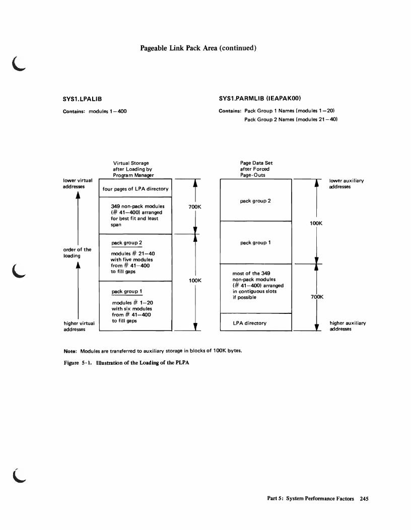
L
Pageable Link Pack Area (continued)
SYS1.LPALIB
Contains: modules 1-400
lower virtual addresses
order of the loading
higher virtual addresses
Virtual Storage after Loading by Program Manager
four pages of LPA directory
349 non-pack modules (# 41-400) arranged for best fit and least span
pack group 2
modules # 21-40 with five modules from # 41-400 to fill gaps
pack group 1
modules # 1-20 with six modules from # 41-400 to fill gaps
700K
lOOK
SYS1.PARMLIB (lEAPAKOO)
Contains: Pack Group 1 Names (modules 1-20)
Pack Group 2 Names (modules 21-40)
Page Data Set after Forced Page-Outs
pack group 2
pack group 1
most of the 349 non-pack modules (# 41-400) arranged in contiguous slots if possible
LPA directory
1 lOOK
lower auxiliary addresses
higher auxiliary addresses
Note: Modules are transferred to auxiliary storage in blocks of lOOK bytes.
Figure 5-1. II1ustration of the Loading of the PLPA
Part 5: System Performance Factors 245
VIO Performance
The use of VIO has both advantages and disadvantages. The installation must decide ..J whether the advantages outweigh the disadvantages for its particular applications.
Advantages
VIO offers the following advantages:
• Virtual I/O pages tend to stay in real storage, if pages are not frequently stolen without being reclaimed. This gives VIO at times the effect of a very large number of buffers. With real data sets, on the other hand, output is done immediately, and on input, buffers are reused.
• DADSM overhead is minimized.
• VIO can improve the CPU efficiency of a user program that has a relatively small blocking factor. With a simulated 3330, with 9 blocks or more per track, VIO uses fewer instructions per track than conventional I/O. With fewer than 9 blocks per track, conventional I/O may be more efficient than VIO, provided that VIO data does not remain in real storage and real I/O occurs to a paging data set.
• The conventional serialization required by Allocation is not required for VIO (see performance topic "Device Allocation").
• The use of paging algorithms, such as ASM's slot sorting, should speed up-VIO operation, compared with conventional I/O (EXCP) by reducing device ....) delays. For output, simulated data transfer can occur without waiting for real I/O to occur to paging space.
• VIO can facilitate improved DASD space management by the installation. If all temporary data sets use VIO, the installation can add to the paging space all of its DASD space previously used for temporary data sets. This should give the system at least as much VIO space as required. When VIO usage is low and other paging requirements are high, the space will automatically be used for non-VIO system paging needs.
246 OS/VS2 System Programming Library: Initialization and Tuning Guide (VS2 Release 3.7)
VlO Performance (continued)
Since auxiliary slots for VIO are allocated by ASM only as they are required (when the window is to be paged out) it may be possible to commit less DASD space for temporary data sets than with conventional I/O. Normally, a programmer allocates DASD space to handle a peak data set size, when in fact only a small portion of that space may be used. The space, however, remains reserved and cannot be used for other purposes. By using VIO, the programmer may still purposely overestimate data set size to insure he will not run out. However, he can be certain that only the space needed for data at any moment will be allocated.
By examining slot usage (through the MF/l Paging Activity report), the installation may be able to remove some of the previously "wasted" DASD space. It would then be able to utilize the space for other purposes, and still support as many temporary data sets as it did previously. (See Part 4: How to Use the System Activity Measurement Facility, Paging Activity Report, for additional information. In using MF/l data for this purpose, the user should note that the Auxiliary Storage User Pool portion of the MF /1 Paging Activity Report indicates a snapshot of slot usage at the end of the report interval. Slot usage is likely to vary during a report interval.)
• The JCL SPACE parameter is enforced for VIO, as it is for conventional access methods. There is also a default space allocation for VIO if the parameter is not specified. The fact that the SPACE parameter (specified or defaulted) is enforced gives the installation some protection against program bugs which could cause a write loop and saturate the paging space. Note that the maximum possible size for one VIO data set is a single volume on the simulated device.
• VIO alleviates the SCRATCH SYS Problem. If an abnormal system termination occurs, there are problems associated with the deallocation of existing real system-named temporaries. For a batch installation, a warm start must be done (with the same packs up) to cause deallocation. Otherwise, SCRATCH SYS must be run on all the packs containing the real temporary data sets. For TSO system-named temporaries, SCRATCH SYS is the only good way to deallocate real temporaries, since restart is not supported.
With VIO, deallocation of temporaries requires only a re-IPL that specifies CVIO (Clear VIO) at warm start or at cold start. All auxiliary slots containing VIO data set pages will be freed regardless of whether or not the volumes on which they reside are mounted.
• VIO is physical device independent. That is, under control of the paging I/O algorithms, the physical device chosen to contain the data set has no relation to the device being simulated. The device chosen will be the best one for the system at the time the I/O is required. No matter how devicedependent the user's code is, VIO will remain device independent.
Part 5: System Performance Factors 247

VIO Performance (continued)
Disadvan tages
These appear to be the disadvantages of VIO:
• VIO for large data sets (particularly if not in update processing) may be less efficient than conventional I/O. Pages from large VIO data sets will be readily stolen and the data forced out to paging space.
• If paging data sets and devices are not carefully organized, the fastest devices can fill up with the less frequently referenced VIO pages. (For suggestions on organizing your paging space, see the performance topic entitled "Guidelines for the Effective Use of Paging Data Sets".)
• VIO is less efficient than conventional I/O for physical data transfer, if the simulated block size is large, i.e., fewer than 9 blocks per track on a 3330. For example, on a 3330 VIO uses slightly fewer instructions to read or write a full track than does EXCP at 9 blocks per track, but with quartertrack blocking VIO requires approximately twice as many CPU instructions per track as does EXCP.
• The system data set SYS1.STGINDEX saves the page data set status of jobs that are eligible for automatic checkpoint or step restart. If SYS1.STGINDEX fills up, the job step can not be restarted.
VIO Performance Considerations
To optimize VIO performance, try to make use of these performance considerations:
• VIO is most efficient for small data sets used for update processing. Such data sets may refer to data pages frequently enough to allow page reclaim. Page reclaim consists of the reuse of a page of data in real storage before it can be written out to paging space. You can measure the relative success of page reclaims by running MF /1, and noting the number of VIO page reclaims listed in the Paging Activity report.
• Allocate VIO data sets by cylinder to minimize overhead. VIO simulates the physical device by software coding. I/O requests are checked for validity against the data set extents. For data sets allocated by cylinders, a check is made for SEEK or SEEK CYLINDER channel command codes. However, for block allocation (the default) or for track allocation, all channel command codes that can cause a reference to any track other than the current must be validity checked which causes additional overhead. This includes SEEK, SEEK CYLINDER, SEEK HEAD, all multi-track commands, overflow READS, etc.
• Use VIO for blocks of data 1200 bytes or less, and lOS for blocks of 3200 bytes or more. Measurements have shown that VIO uses fewer CPU instructions to process a 1200 byte (or less) block of data than lOS; lOS uses fewer instructions than VIO to process a 3200 byte (or more) block of data. For the range of blocksizes between 1200 and 3200, VIO should be used if the system has light paging activity.
248 OS/VS2 System Programming Library: Initialization and Tuning Guide (VS2 Release 3.7)

L
VIO Performance (continued)
• It's best to choose a block size whose multiple (plus block headers and window control record) almost completely fill the pages that comprise the window. The VIO "window" that is written out to paging space is always equal to the used portion of the track size (data plus track overhead) rounded up to the next multiple of 4K. Although the window, when full, is always four pages for a 3330, the amount of data transferred depends on the number of bytes of the data on the simulated track. Avoid a block size that requires an additional page for the window without significantly increasing the data being transferred. For example, a block size of 2035 uses a three-page window to transfer 12,210 bytes of useful data, plus 8 bytes for each block header and 30 bytes for a window control record, at six blocks per track. (This is a total of 12,288 bytes.) In contrast, a block size of 2036 bytes uses a fourpage window to transfer 12,216 bytes of useful data, plus 8-byte block headers and a 30-byte window control record, for a total of 12,294 bytes, also at six blocks per track. However, the 2036-byte block size needs an extra page in the window, consisting of 4090 wasted bytes, to transfer 6 additional bytes of useful data.
• VIO data sets ought not be allocated and held for long time sharing sessions. Since temporary data sets are usually freed only at the end of a TSO session, the total paging space in use can become excessive. The installation can control the total allocated VIO space per TSO session, possibly by means of a DAIR exit.
• Consider chained scheduling for non-VIO data sets. The use of OPTCD=C, together with an increase in the number of buffers (for example, BUFNO=6), has been found to significantly reduce system instructions in some batch environments.
How to Specify VIO Data Sets
The following are the requirements for specifying VIO data sets:
• The UNITNAME macro at sysgen must specify VIO=YES. Both generic and esoteric names are accepted. With an esoteric name, the first unit in the list must be a direct access device. A generic name must be DASD and should not specify a unit list.
• The data set must be specified or defaulted as temporary (NEW,DELETE or NEW ,PASS).
• The volume request must be non-specific (i.e., no volume serial number).
• The total SPACE parameter - primary and used secondary - can not exceed one volume on the device being simulated. The primary space specification will be accepted up to a value of one volume on the simulated device. The default space value is (1000,(10,50».
• The data set should have no dsname or should be specified by &name.
• VIO cannot be used for VSAM or ISAM data sets.
• The unit count subparameter of the DD UNIT parameter is ignored.
Part 5: System Performance Factors 249

VIO Performance (continued)
Questions and Answers
The folloWing questions are those that customers have asked regarding VIO.
Q: What is the effect of VIO usage when going from a paging load of light to heavy? Is there a mechanism or procedure to offset any negative effect?
A: The effect consists of possibly increased I/O and CPU overhead. Both factors slow VIO performance. However, CPU overhead may not increase proportionately with increased paging, since the Auxiliary Storage Manager may be able to chain more pages together for I/O. One answer would be to provide more paging devices, faster paging devices, and different channel paths. Another solution would be to obtain more real storage.
Q: Are there any advantages in simulating a 2314 for VIO data sets if the paging device is a 3330 or 2305, even though no 2314s may actually be in the system?
A: Yes, if you have code that depends on the device being a 2314. Be sure that an 10DEVICE macro at sysgen specified a 2314, at a unique address, even though there are no physical 2314s on the system.
Q: Does VIO fill the window for an input data set as an anticipatory paging operation?
A: No. The window is filled only as the result of input requests.
Q: The track capacity of a simulated 3330 for VIO requires a four-page window. However, if I block my data 1680 bytes per block, the seven blocks will fit in the first three pages of the window. Are all four pages paged out?
A: No. Only those pages that have data are paged out.
Q: Can a job that runs ADDRSPC=REAL use VIO?
A: Yes.
250 OS/VS2 System Programming Library: Initialization and Tuning Guide (VS2 Release 3.7)

L VIO Performance (continued)
Q: Ifpaging error occurs with a VIa data set, does a user SYNAD exit get control?
A: No. (For discussion of paging error handling, see the Questions and Answers section in the topic "Guidelines for the Use of Paging Data Sets".)
Q: Is there a limit to the size of a VIa data set? If so, how is it specified?
A: The size of a VIO data set can be limited via the JCL SPACE parameter in the same manner as with non-VIO data sets. The maximum size of a VIO data set is one volume of the device type being simulated.
Q: Do you have one window per active VIa data set or one per address space?
A: One per data set. This applies no matter how many DCBs the user may have open to the data set.
Q: What happens when the user buffer size is greater than VIa window size?
A: A buffer size (block size) that is larger than the window size can be valid only if the track overflow feature is being simulated, since the window size is equal to one track of the device being simulated, rounded up to the next 4K. If track overflow is not being simulated, an error indication (blocksize larger than physical track size) will be returned.
Q: Can UNITNAMEmacro at sysgen contain Vla= YES for a device not installed at the installation?
A: A device can be simulated that is specified at sysgen, via both the UNITNAMEand IODEVICE macros, but which is not physically online to the sys tern .
Q: Does PCI work with VIO?
A: Yes. EXisting programs that use the PCHeature will work with VIO. However, the 'user should understand that the I/O is being simulated, and the PCI interrupts and associated processing have no relation to the real I/O to the paging data sets.
Q: Is the windaw block-paged or individually paged?
A: The window is:block p~ed_on output but is individually paged on input, via a page fault.
Part 5: System Performance Factors 251

Device Allocation Performance
This topic discusses how an installation can improve performance through the allocation of devices, data sets, and volumes. The first section describes the order in which allocation requests are serviced. The remainder of the topic provides gUidelines for improving allocation response.
Note: For SRM influences on Device Allocation, see the "Device Allocation Routine" in the chapter "How to Use the System Resource Manager". For Auxiliary Storage Manager influences on the selection of paging devices, see the performance topic "Guidelines for the Effective Use of Paging Data Sets".
The Order in Which Allocation Requests Are Serviced
The order in which allocation requests are handled by the system affects the processing time and the degree of serialization of particular allocations. To reduce serialization, allocate your data sets, volumes, and devices from the categories high on the following list, if possible. As you move down the list, the degree of serialization and the processing time increase.
1. VIO data sets, JES2 or JES3 data sets, and dummy data sets.
2. Permanently resident or reserved direct-access volumes (see the V ATLSTxx description in the Initialization chapter for information on the' specification of these volumes).
3. Teleprocessing devices; and generic device types as specified in the device precedence list, except devices which hold permanently resident or reserved DASD volumes. (See the gUideline later in this topic on the use of the DEVPREF keyword of the SCHEDULR macro to specify the device precedence list.)
4. Unmounted nonspeCific direct access volumes. These requests cause serialization with other allocations until the operator mounts the volumes.
5. Offline devices and devices allocated to another job. These requests require operator interaction.
252 OS!VS2 System Programming Liblary: Initialization and Tuning Guide (VS2 Release 3.7)

L
L
Device Allocation Performance (continued)
Guidelines for Improving Allocation Response
The folloWing suggestions should help your installation to make best use of the redeSigned Device Allocation routines:
• Within the limit of page space availability, encourage the use of VIO data sets. (For further information, see the topic entitled "VIO Performance".)
• Set up a sufficient number of permanently resident and reserved DASD volumes on line, to avoid contention for a few volumes of these types. You can check for contention by running MFjl to obtain device activity reports. The volumes should be spread across channels so that the System Resource Manager can balance the channel load.
• Use the UNITNAME sysgen macro to define separate esoteric subgroups within major generic device types, so that different subsets of users can request separate subgroups of devices. The purpose is to minimize contention for the same devices among the various subsets of users. For example, an installation whose batch and time sharing users request allocation of 3330's could separate the two types of user requests as follows:
UNITNAME UNIT=(330,4) ,NAME=SYSBATCH
UNITNAME UNIT=(334,4) ,NAME=SYSTSO
The effect of this specification is that allocations to SYSBATCH serialize only requests for units 330-333, instead of the entire 3330 generic. Similarly, allocations to SYSTSO serialize only requests for units 334-337.
• Use the DEVPREF keyword of the SCHEDULR sysgen macro to minimize contention for the fastest devices. The DEVPREF keyword sets up the device preference table. The table determines the order in which device types will be selected by Allocation if a request is eligible for more than one device type (e.g., UNIT=SYSDA). If the keyword is not specified, the default device preference table lists the fastest generics first. If such specification causes heavy contention for the fastest eligible devices, you can specify the DEVPREF list so that generics with many devices (and many channels) are listed first and are therefore given preference. As as secondary consideration, the increased number of preferred units and channels will give the System Resource Manager a large selectionfor its choices.
• Keep all operable devices online if possible. (This is old advice and does not depend on the redesign of Device Allocation.)
• Try to avoid the use of specific unit address (e.g., UNIT=253) in DD statements for volumes that are neither permanently resident nor reserved. A specification of specific unit address serializes the request on the entire device type. For example, if unit 253 is a 3330, a specific unit request (UNIT=253) will be serialized with other requests for any 3330. Instead of using specific unit address, use subsets of the generic device type, as suggested earlier in this topic.
Part 5: System Performance Factors 253
Device Allocation Performance (continued)
• Resolve the question whether the operator should respond HOLD or NOHOLD when a job must wait for other jobs to free devices or volumes, and a message is issued to the operator. The criteria for resolving the question are:
HOLD
NOHOLD
This means that the job should wait while holding devices and volumes already allocated to the job. Select this option if the needed resources are constantly being freed, and allocation requests for other jobs will probably not be held up by the requests made for this job. This job can hold up other requests in either of two ways: it has already allocated units needed for another job, or its allocation requests are serialized on devices it is waiting for.
This means that the job waits without holding devices and volumes already allocated to the job. Select this option if the needed resources may not be freed for some time, and allocation requests for this job are likely to hold up requests issued for other jobs.
Note: Requests for dynamic allocation are not held up by requests waiting for batch allocation, even though the jobs awaiting batch allocation are holding resources.
• Free data sets, volumes, or devices before the end of a job step or TSO session, if possibfe. The freed resources can then be used for other jobs or sessions. You can free the resource when a data set is closed, by specifying FREE=CLOSE on the associated DD statement. (This option is a new facility in MVS.) Note that when subsequent steps of a job require the same data set, the resource must be reallocated prior to being reaccessed (or else the OPEN fails). Use discretion when freeing the resources, however, because once a resource is freed, its continuing availability cannot be guaranteed.
• Invoke Dynamic Allocation from a batch job by means of a new application of SVC 99. (The details are described in as/VS2 System Programming Library: Job Management.) The advantage is that the batch job allocates the resource only when it is needed, and frees it as soon as it is not needed. (FREE=CLOSE can also free the resource, if it is specified on a DD statement.) Resources are thus more readily available to other requesting jobs. A disadvantage is that the batch job must handle a return code if the requested resource is not available. (With conventional allocation via DD statements, the system would cause the job to wait for the requested resource(s) to become available.) Note, however, that an authorized program need not handle a return code if a requested resource is not available. The authorized program can request a "wait for the resource" when it invokes Dynamic Allocation. (Unfortunately, there is no deadlock detection in this case.)
254 OS/VS2 System Programming Libmry: Initialization and Tuning Guide (VS2 Release 3.7)

L
Device Allocation Performance (continued)
• Premount all private volumes, including private catalogs, before running the jobs that request these volumes. (This is another piece of old advice.) Note, however, that AVR (Automatic Volume Recognition) is no longer optional.
TSO Allocation Suggestions
The following suggestions should improve TSO allocations during TSO sessions although they may extend log-on times:
• DD statements that a user wants in all his TSO sessions should be placed in a LOGON procedure. This technique has these advantages:
I.Allows volumes to be mounted.
2. Provides recovery from an offline device condition. Messages tell the operator to VARY the device online.
3. Saves repeated allocation and freeing of the same data set by successive commands in the same TSO session.
• The DYNAMNBR parameter value in the EXEC statement should be carefully chosen. The value should be large enough so that it is not readily exceeded by dynamic allocation requests. Note that the maximum number of concurrently allocated resources for any TSO session is 1635.
How the SRM Allocation Algorithm Affects I/O Load Adjusting
The SRM I/O Load Adjusting algorithm employs address space swapping as its control mechanism. When such a correcting swap takes place, all of a job's (or TSO command's) I/O load either disappears for a swap-out or reappears for a swap-in. When a job's data sets are widely distributed across many logical channels, the swapping of that job affects the load on all of these channels, and will probably not correct any I/O load imbalances present across these logical channels. The reason is that it is unlikely that the currently over or underloaded channels will coincide precisely with the channel dependencies of a job with widely distributed data sets. Accordingly, the swapping of such ajob may remedy some imbalances, but may also aggravate others. If the job's I/O dependencies are localized to a single logical channel, swapping of the job to correct an imbalance will have a more predictable effect. The SRM I/O load adjusting algorithm tries to identify jobs that would have such an ambiguous effect, and eliminates them as swap candidates.
Minimizing a particular job's execution time, which may depend on channel separation, is often in direct conflict with the objective of localizing a job to a few logical channels in order to support I/O load adjusting. The SRM Device Allocation algorithm provides a flexible scheme through which the installation may emphasize either one of these conflicting objectives. (See the Device Allocation routine description under Resource Use Routines in Part III: How to Use the System Resources Manager, and constant ICCEDSUT in Figure 3-7.)
Part 5: System Performance Factors 255

Device Allocation Performance (continued)
In practice, it is not always possible to restrict a job's I/O dependencies to a single channel. However, any reduction in the job's I/O dependencies will improve the job as a candidate for correcting I/O load imbalances. Accordingly, the SRM Device Allocation algorithm selects channels with the objective of minimizing a job's logical channel dependencies.
The same strategy should be followed by job submitters. This is particularly important in the case of jobs which do a considerable amount of I/O over a sustained period of time. It is of course important that not all jobs choose their data sets through the same logical channel(s). This suggests some understanding between the installation and its heavy I/O users, supplemented by the use of job classes. The job classes must ensure a good distribution of jobs with different logical channel dependencies.
An important secondary benefit is realized from this allocation strategy. When a particular channel has an uncorrectable overload, every address space which depends on this channel has its processing slowed by the slow channel response. If many of the executing address spaces are slowed by such a dependency, the result is a significant drop in throughput, accompanied by a drop in the utilization of other system resources. This drop occurs because many address spaces spend much time waiting on the overloaded channel. If, however, some jobs do not depend on the overloaded channel, they will not be slowed by the overload, and they will be able to take advantage of the lowered demand for other resources. Consequently they will run faster than would normally be the case.
Questions and Answers
The following Allocation question has been asked by customers:
Q: The Device Allocation algorithm in the System Resources Manager tries to minimize the number of logical channels used by a batch job or TSO session. What happens if a job's execution time depends on channel separation?
A: Use specific unit allocation or an esoteric name eligible to a single channel.
256 OS!VS2 System Programming Libruy: Initialization and Tuning Guide (VS2 Release 3.7)

VSAM Catalog Performance
Note: These guidelines pertain to VSAM catalogs only, not to OS CVOLs. For information on OS CVOL usage under the VSAM master catalog, refer to OS/VS2 Using OS Catalog Management With the Master Catalog: CVOL Processor. Additional catalog information can be found in the OS/VS Virtual Storage Access Method (VSAM) Programmer's Guide. Additional tuning aids are described in "Chapter 3: Catalog Conversion" of the OS/VS2 Conversion Notebook
The performance of VSAM catalogs can be improved by adhering to the following guidelines:
• Choose a primary space value large enough to hold the data to be cataloged, but do not grossly overspecify. Excessive unused s~ace wastes seek time. Secondary space allocation should however be specified to avoid reorganization of the catalog at inconvenient times if the primary space becomes full. Try to arrive at a value for primary space such that secondary space is used only for occasional overflow. A formula is available in OS/VS2 System Programming Library: Storage Estimates for the calculation .
• Specify a sufficiently large BUFFERSPACE value in the DEFINE MASTERCATALOG and DEFINE USERCATALOG commands* for each shared VSAM catalog in order to maximize the number of concurrent searches (LOCATEs) of the VSAM master catalog and each job-shared VSAM user catalog. If, however, a VSAM user catalog is not shared across jobs, there is no need to provide the capability for concurrent searches.
The buffer (defined by BUFFERSPACE) is used for the reading of the index and data portions of the catalog. The minimum or defaulted specification of 3K bytes of page able virtual storage allows two concurrent searches of the catalog. Each additionallK bytes permits one more concurrent search, up to a maximum of seven concurrent searches at a BUFFERSPACE value of BK. (Thus, a BUFFERSPACE value of 4K would allow three concurrent searches.) A maximum of one catalog search per address space at one time is possible, except if there is user subtasking, in which case more than one concurrent catalog search per address space is possible.
Note: The BUFFERSPACE value should be specified as or defaulted to the minimum (3K) for a VSAM user catalog that is not shared across jobs.
*The DEFINE commands are described in OS/VS2 Access Method Services. The STEPCAT or JOBCAT DD statement for a VSAM user catalog can also speCify buffer size, via the BUFSP subparameter of the AMP parameter. (See OS/VS2 JCL.) If both the DEFINE command and JCL specify buffer size, the larger specification overrides the smaller. In other words, the JCL speCification can increase the buffer size but not decrease it.
Part 5: System Performance Factors 257

It
VSAM Catalog Performance (continued)
• Although a large BUFFERSPACE value is good for shared VSAM user catalogs, don't overspecify. There are three reasons:
1. A BUFFERSPACE value of more than 8K is automatically reduced to 8K without increasing the number of concurrent catalog searches beyond the maximum of seven.
2. Each increase in BUFFERSPACE value beyond the minimum (3K) requires additional fixed storage, at the rate of 224 bytes of fixed storage for each 1 K bytes of increased specification. Thus, a BUFFERSPACE value of 8K would require 1568K bytes (448 + 5 x 224) of flXed storage.
3. Concurrent searches can occur only when the catalog is being referenced (for example, by Allocation or Open). Concurrent searches will result only to the extent that such referencing occurs simultaneously in two or more address spaces. If a catalog is not shared, there will be no concurrent searches.
• I/O operations to a catalog are performed by use of a control block called a Request Parameter List (RPL). The number of RPLs determines the maximum number of concurrent Locates that can be done. When all the RPLs are in use, the next Locate wlli cause an exclusive enqueue on the RPL resource. The dequeue will not be done until this Locate completes, thus allowing only one Locate at this time. The number of RPLs is determined by the BUFFERSPACE value specified on the DEFINE MASTERCAT ALOG or DEFINE USERCATALOG command, or as altered by the ALTER CATALOG command. The larger the BUFFERSPACE size, the greater the number of RPLs. Therefore, in systems where storage is not a critical resource, the BUFFERSPACE parameter value should be increased to 8K for more efficient Locate performance. In systems where storage is at a premium, the default value of 3072 bytes is recommended.
• The installation may wish to use the same VSAM catalog for jobs that normally run concurrently. (Note that although concurrent searches can be shared, updates always require exclusive access to the catalog.) You may connect concurrently running jobs to the same VSAM user catalog (e.g., ten jobs to one catalog) in order to optimize the use of fixed storage and reduce execution time. One way this can be done is by specifying the same catalog name in the JOBCAT DD or STEPCAT DD statements for the concurrent jobs. In this case, specify a relatively large BUFFERSPACE value, up to 8K. The disadvantage of catalog sharing, however, is that the jobs will contend for tht' use of the shared catalog.
258 OS!VS2 System Programming Library: Initialization and Tuning Guide (VS2 Release 3.7)

VSAM Catalog Performance (continued)
• Avoid a lot of user catalogs in systems where storage is a critical resource. Improved response times have been observed in a two megabyte environment when the number of user catalogs has been reduced from six to two. Fewer user catalogs will require less fixed storage, and can improve response times.
• You may improve catalog search speed by placing all data sets of a job or step, if possible, in the same VSAM user catalog. The catalog should preferably be identified by a JOBCAT or STEPCAT DD statement. Such identification is useful because the catalog search begins with catalogs identified by JOBCAT or STEPCAT DD statements. However, even without such identification some search time can be saved, if data sets used in job steps or time sharing sessions have the same highest level dsname qualifier. In this case, the VSAM master catalog will be searched the first time that a data set must be found. Subsequent searches will bypass the master catalog and go directly to the appropriate user catalog.
Part 5: System Performance Factors 259
VSAM Catalog Performance (continued)
Questions and Answers
The following questions on the VSAM catalog have been asked by customers.
Q: Will connected CVOLs and STEPCATorJOBCAT catalogs be mounted at interpreter time?
A: In general, no. The catalogs are mounted at the time they are allocated.
Q: How serious is the loss o/the VSAM master catalog to MVS?
A: If there are no VSAM data sets represented in the master catalog, other than paging, the catalog itself, and SYSI.STGINDEX, then the impact is similar to losing an OS master catalog. If VSAM data sets exist, then VSAM recovery techniques and considerations apply. (See OS/VS Virtual Storage Access Method (VSAM) Programmer's Guide.) The VSAM master catalog, as well as paging data sets and SYSI.STGINDEX, must be rebuilt on an MVS system. Non-VSAM data sets still have VTOC entries and can be recataloged.
If the VSAM master catalog can't be opened, or if certain system data sets can't be found (via LOCATE macros), the system can't be initialized. If there are catalog problems after system initialization, the impact to the system depends on the degree of reliance on the catalog and on the fraction of the catalog that is unusable. (It is unlikely that the entire master \ catalog will become unusable at the same time.) "'fIlII
Q: Under what circumstances should an installation convert its OS CVOLs to VSAM user catalogs?
AI: Use CVOL support and do not immediately convert CVOLs to VSAM user catalogs, if you have varied systems, some under MVT and one or more under MVS, and you wish to use your data on both systems. As applications are moved to the MVS system(s), gradually move the data sets to VSAM user catalogs for improved performance and easier maintenance* .
A2: Convert OS CVOLs to VSAM user catalogs, via the CONVERTCAT utility, for improved performance and easier maintenance *, if you have one or more MVS systems that have users with CVOLs, and there are no longer any MVT systems at your installation. Such conversion is desirable even though the VSAM master catalog could continue to point to the CVOLs.
*Utilities IEHLIST and IEHPROGM do not have full function for OS CVOLs under MVS.
260 OS!VS2 System Programming Library: Initialization and Tuning Guide (VS2 Release 3.7)

L
L
How SMF Can Supplement MF/l
MF /1 records or reports can be used to identify intervals during which the utilization of certain system resources has been unusual. MF/l data includes infor· mation on CPU, the paging subsystem, channels and devices, pageable real storage, and workload activity. SMF can be used concurrently to list information that describes the workload processed during the same time interval. There may be a correlation between unusual resource utilization and the processing of particular batch jobs or time sharing sessions.
MF /1 can be used to determine the average system workload level over a relatively long period of time. SMF can be used during the same period to identify the exceptional jobs, jobsteps, and TSO sessions that received service rates significantly different from those defined in the IPS at that workload level. Exceptional jobs or TSO sessions are those that either receive unusual service or place exceptional demands on system resources. System resources consist of the paging subsystem, the CPU, channels, devices, real storage, etc.
Exceptional jobs or TSO sessions can be identified by summarizing SMF statistics*. When these jobs and sessions have been identified, the installation can investigate the reasons for the exceptional service or demands, and then make changes. For example, a change to the blocking factor may turn a heavy I/O-demand job into an average I/O-demand job receiving average service.
MF/l and SMF together can be used for at least the following purposes:
• Comparison of paging rates for a problem program and the system • Comparison of I/O activity for a problem program and the system • Comparison of problem program service versus total service • Determining changes to the system configuration
Comparison of Paging Rates for a Problem Program and the System
This program-versus-system comparison can suggest paging problems within the problem program. The program's paging rate is indicated by SMF record types 4 and 34 (see as/vs System Management Facilities (SMF). The installation can calculate paging rate for the jobstep from the formula:
Paging rate = jobstep pages in and out / CPU time for the jobstep.
A similar rate for the system can be determined during the same time interval from SMF record types 70 and 71. Type 70 contains the length of the measurement interval and the CPU wait time during the interval. Type 71 contains paging data, including page-ins and page-outs, and the interval length. The system calculation is basicalIy the same as the job step calculation stated above, except that CPU time must first be determined by subtracting CPU wait time from the total time interval.
*The Statistics Gathering Program (SGP) is available as a data reduction tool for SMF data. The program is distributed as field-released program No. 5798-A VY.
Part 5: System Performance Factors 261

How SMF Can Supplement MF/I (continued)
Comparison of I/O Activity for a Problem Program and the System
This program-versus-system comparison on first observation seems to be one of apples to oranges, since MF/l counts SIOs, and SMF counts EXCPs (which include SVCO's, PCI interrupts, channel-end interrupts, and abnormal-end interrupts). It is possible, however, to obtain a ratio of EXCPs to SIOs by using the sum of the jobstep EXCPs from SMF and the sum of the SIO counts from MF/l for the same measurement period. When you have established this I/O ratio, you may be able to detect those jobsteps whose I/O operations seem excessive. Appropriate corrective action can then be taken.
Comparison of Problem Program Service and Total Service
The installation can compare the service given to particular performance groups versus total system service by examining SMF record types 5 and 35, and comparing their data with that in record type 72 which is produced by MF/l. Record types 5 and 35 contain the number of service units required by a job or TSO session. Record type 72 gives the total service provided for all jobs and TSO sessions. By comparing the data from these two sources, the installation can determine whether service is being distributed according to the goals of the installation.
Determining Changes to the System Configuration
SMF provides information on the system configuration at IPL and changes to that configuration while the system is running. The data is contained in record types 0, 8,9, 10, 11,22,70, 73, and 74. This information is important during analysis of MF /1 data, since it can explain significant changes in the MF /1 output. Explanation of these changes might otherwise be left to speculation or to an exhaustive study of the operator's console output.
262 OS/VS2 System Programming library: Initialization and Tuning Guide (VS2 Release 3.7)

The Use of GTF to Track Sysevents
record Field identifier Name length reserved (AID)
X'FF' (See note 1)
Length 2 2
Hex Offset 0 02 04
Notes:
System components issue the SYSEVENT macro to inform the System Resource Manager (SRM) that the status of an address space or a system resource has changed. (The SYSEVENT is somewhat analogous to the TSEVENT macro in MVT.) The SRM is informed of critical changes to the availability of real storage frames, auxi· liary storage slots, and SQA virtual space. In addition, the SYSEVENT may request that the SRM perform a service. For example, the REQSERVC sysevent (code X'26') is issued to request that the SRM obtain service data related to a particular address space. (See Figure 5·3 at the end of this topic for descriptions of the various SYSEVENT codes.)
The installation can monitor SYSEVENT activity during a selected time interval by starting GTF with the SRM option. The SRM option causes GTF to write a trace record each time a SYSEVENT macro is issued. (Information on how to use GTF is available in OS/VS2 System Programming Library: Service Aids.) The SYSEVENT trace record contains a time stamp, an address space control block (ASCB) address, a CPU identification (CPUID), a jobname (if applicable, and if comprehensive trace records have been requested), and contents of regs 0, 1, and 15 which contain information peculiar to the particular SYSEVENT. The information includes the SYSEVENT code that indicates why the SRM was invoked. (See Figure 5·2 for the format of the SRM trace record.)
format event identifier identifier ASCe R15 RO R1
(FlO) timestamp (EID) addr CPUID jobname contents contents contents X'04' X'4001' (See
(See (See note 4) note 2) note 3)
8 2 4 2 8 4 4 4
05 06 OE 10 14 16 1E 22 26
1. The record identifier (AI D) in GTF records is a one..tJyte hexadecimal number that identifies the record as a trace record 0 r a control record.
3. The event ide[ltifier (EID) in GTF trace records is a two..tJyte hexadecimal number that defines the event that caused the record to be built. The EID is in the form cddd where c is the event class (O·F) and ddd is the I D of the event within the class.
2. The format identifier (FID) in GTF records is a one..tJyte hexadecimal number that is used to determine the name of the AMDPRDMP EDIT module that will format the record.
I Figure 5·2. SRM Trace Record Format
4. Jobname appears only in the comprehensive trace record. Comprehensive format must be requested when GTF is started.
Part 5: System Performance Factors 263

The Use ofGTF to Track Sysevents (continued)
The installation should reduce the trace data to determine the utilization of system resources and the service given to particular jobs or TSO sessions. The reduced data can supplement that obtained from MF/1 and SMF (see the performance topic "How SMF Can Supplement MF/l"). For example, the trace data can indicate when shortages in paging space occur. This information can be used with SMF data to learn the identify of jobs and TSO sessions active at the time of the shortage. Possible corrective action may include the addition of more paging space, or external scheduling at the installation to prevent all the heavy paging jobs (possibly VIO users) from running at the same time.
Swapping is the primary mechanism used by the SRM to control response and throughput. Yet the only information that MF/l provides on swapping is the system swapping rate. However, if the rate is excessive, the SYSEVENT trace data can be used to identify jobs or TSO users which are causing excessive swapping. Possibly the situation can be relieved by making adjustments to the ISV fields in the installation's IPS.
The sysevent data can be used to analyze the effect of the system running with insufficient SQA virtual storage. Distributions can be produced which identify the frequency and durations of the shortage periods. These intervals can be correlated with MF/I data to determine how the SQA shortage affects CPU utilization, channel utilization, and service unit utilization. If the shortage time is excessive or if it causes a significant degradation of performance, the installation can make more space available for SQA virtual storage.
Similarly, the sysevent data can be used to analyze the effect of the system running with a shortage of available page frames, i.e., in an AVQLOW* environment. If the shortage time is excessive or if it impacts performance, the installation may wish to modify the Real Storage Manager (RSM) constants that define the shortage.
A sysevent trace tape can be sorted by address space ID (ASID), sysevent type, or by time of occurrence, etc. The sort yields a sequence of tabulated records for each job or TSO session. The time difference between the individual printed records is the time between significant stages of a job or TSO session. The stages include such items as address space creation,job selection, (START, MOUNT, or LOGON issued), initiator attaching a task, initiator detaching a task, and job termination. The sequence also contains a record for each time the address space is swapped into or out of real storage. For a TSO session, the sequence contains a record of each time the address space enters wait state and each time it becomes ready.
*SYSEVENT X'IT
264 OS/VS2 System Programming library: Initialization and Tuning Guide (VS2 Release 3.7)

L
L
L
The Use of GTF to Track Sysevents (continued)
Through appropriate reduction of the data, the installation can obtain some meaningful time distributions. Some examples are:
• time needed to swap an address space in • time needed to swap an address space out • time address spaces spend in real storage • time address spaces spend out of real storage • user think time • system response rate • transaction arrival rate • transaction processing rates • job processing rates • TSO session durations
Information is also provided in the trace which identifies the names of time sharing commands and sub commands (see sysevent code 00 in Figure 5-3). This information should help the installation to produce time distributions for the individual TSO commands and subcommands.
Figure 5-3 describes the meaning and input information (register contents) for each sysevent type.
Figures 5-4 through 5-8 show sample printouts of a data-reduced sysevent trace. Note that unusual data are circled and annotated.
Sysevent Code:
Mnemonic:
Meaning of Mnemonic:
Circumstances:
Inputs:
Outputs:
00
TSEVENT 00 (PPMODEl
A time sharing command, or a subcommand of EDIT or TEST, is to be executed.
The TSO Terminal Monitor Program or the EDIT/TEST command processor issues this sysevent when the command or subcommand is about to be executed. It causes no action on the part of the SRM.
Reg 0, bytes 0-3: ASI D Reg 1, bytes 0-3: Contains the first four characters of the command or subcommand name. Reg 15: Contains the last four characters of the command or subcommand name.
None
Figure 5-3. Descriptions of SYSEVENT Codes (Part 1 of 24)
Part 5: System Performance Factors 265
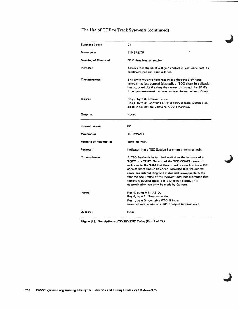
The Use of GTF to Track Sysevents (continued)
Sysevent Code:
Mnemonic:
Meaning of Mnemonic:
Purpose:
Circumstances:
Inputs:
Outputs:
Sysevent code:
Mnemonic:
Meaning of Mnemonic:
Purpose:
Circumstances:
Inputs:
Outputs:
01
TIMEREXP
SRM time interval expired.
Assures that the SRM will gain control at least once within a predetermined real time interval.
The timer routines have recognized that the SRM time interval has just popped (elapsed), or TOO clock initialization has occurred. At the time the sysevent is issued, the SRM's timer queue element has been removed from the timer Queue.
Reg 0, byte 3: Sysevent code Reg 1, byte 3: Contains X'Ol' if entry is from system TOO clock initialization. Contains X'OO' otherwise.
None.
02
TERMWAIT
Terminal wait.
Indicates that a TSO Session has entered terminal wait.
A TSO Session is in terminal wait after the issuance of a TGET or a TPUT. Receipt of the TERMWAIT sysevent indicates to the SRM that the current transaction for a TSO address space should be ended, provided that the address space has entered long wait status and is swappable. Note that the occurrence of this sysevent does not guarantee that the entire address space is in a long wait status. This determination can only be made by Quiesce.
Reg 0, bytes 0-1: ASIO. Reg 0, byte 3: Sysevent code. Reg 1, byte 0: contains X'OO' if input terminal wait; contains X'SO' if output terminal wait.
None.
Figure 5·3. Descriptions of SYSEVENT Codes (part 2 of 24)
266 OS{VS2 System Programming Library: Initialization and Tuning Guide (VS2 Release 3.7)

L
The Use of GTF to Track Sysevents (continued)
Sysevent Code:
Mnemonic:
Meaning of Mnemonic:
Purpose:
Circumstances:
Inputs:
Outputs: ,
Sysevent Code:
Mnemonic:
Meaning of Mnemonic:
Purpose:
Circumstances:
Inputs:
Outputs:
03
NIOWAIT
Address space suspected of being in long wait.
Indicates to SRM when an address space is suspected of having entered long wait.
Some task in the address space just entered long wait. Occurrence of this sysevent does not guarantee that the entire address space is in a long wait status. This determination can be made only by Quiesce. The time spent by a swappable address space in long wait will not be considered part of the current transaction for that address space.
Reg 0, bytes 0-1: ASID or zero. Reg 0, byte 3: Sysevent code
None.
04
USERRDY
User ready.
Indicates that an out-of-core address space or an address space for which Quiesce is running has at least one dispatch able unit (SRB)* which is ready to run.
Something has occurred causing a dispatchable unit (SRB) to be scheduled to this address space.
Reg 0, bytes 0-1: ASID. Reg 0, byte 3: Sysevent code.
None.
*SRB means system resource block.
I Figure 5-3. Descriptions of SYSEVENT Codes (part 3 of 24)
Part 5: System Perfonnance Factors 267
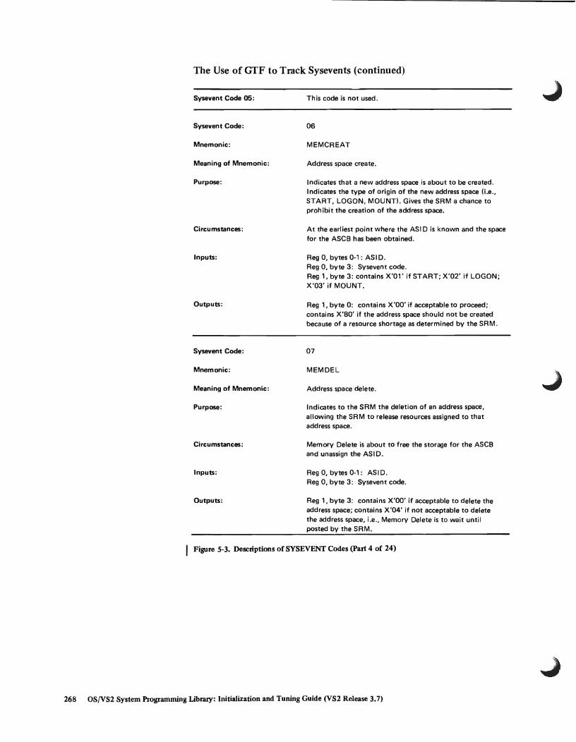
The Use of GTF to Track Sysevents (continued)
Sysevent Code 05:
Sysevent Code:
Mnemonic:
Meaning of Mnemonic:
Purpose:
Circumstances:
Inputs:
Outputs:
Sysevent Code:
Mnemonic:
Meaning of Mnemonic:
Purpose:
Circumstances :
Inputs:
Outputs:
This code is not used.
06
MEMCREAT
Address space create.
Indicates that a new address space is about to be created. Indicates the type of origin of the new address space (i.e., START, LOGON, MOUNT). Gives the SRM a chance to prohibit the creation of the address space.
At the earliest point where the ASI D is known and the space for the ASCB has been obtained.
Reg 0, bytes 0·1: ASID. Reg 0, byte 3: Sysevent code. Reg 1, byte 3: contains X'01' if START; X'02' if LOGON; X'03' if MOUNT.
Reg 1, byte 0: contains X'OO' if acceptable to proceed; contains X'SO' if the address space should not be created because of a resource shortage as determined by the SRM.
07
MEMDEL
Address space delete.
Indicates to the SRM the deletion of an address space, allowing the SR M to release resources assigned to that address space.
Memory Delete is about to free the storage for the ASCB and unassign the ASID.
Reg 0, bytes 0·1: ASID. Reg 0, byte 3: Sysevent code.
Reg 1, byte 3: contains X'OO' if acceptable to delete the address space; contains X'04' if not acceptable to delete the address space, i.e., Memory Delete is to wait until posted by the SRM.
Figure 5·3. Descriptions of SYSEVENT Codes (part 4 of 24)
268 OS(VS2 System Programming Library: Initialization and Tuning Guide (VS2 Release 3.7)

L
The Use of GTF to Track Sysevents (continued)
Sysevent code:
Mnemonic:
Meaning of Mnemonic:
Purpose:
Circumstances:
Inputs:
Outputs:
Sysevent Code:
Mnemonic:
Meaning of Mnemonic:
Purpose:
Circumstances:
Inputs:
Outputs:
08
JOBSELCT
Job selection.
Indicates that an address space has started using system services on behalf of a new job, START or MOUNT command, or a TSO' session.
Whenever IEFS0161 handles one of the above.
Reg 0, bytes 0-1: ASIO or zero. Reg 0, byte 3: Sysevent code. Reg 1, bytes 0-3: pointer to jobnarne or user 10.
None.
09
JOBTERM
Job termination.
Indicates that an address space has completed using system services on behalf of a job, START or MOUNT command, or a TSO session.
Whenever IEFS0166 handles one of the above.
Reg 0, bytes 0-1: ASIO or zero. Reg 0, byte 3: Sysevent code. Reg 1, bytes 0-3: pointer to jobname or user 10.
None.
I Figure 5-3. Descriptions of SYSEVENT Codes (Part 5 of 24)
Part 5: System Performance Factors 269

The Use of GTF to Track Sysevents (continued)
Svsevent Code:
Mnemonic:
Meaning of Mnemonic:
Purpose
Circumstances:
Inputs:
Outputs:
Svsevent Code:
Mnemonic:
Meaning of Mnemonic:
Purpose:
Circumstances:
Inputs:
Outputs:
OA
INITATT
Attach bV initiator.
Indicates an initiator has attached a task. Is related to a JOBSELCT svsevent (code 8).
Whenever IE FSD263 attaches a task.
Reg 0, bytes 0-1: ASID or zero. Reg 0, byte 3: Svsevent code. Reg 1, byte 2: Performance Group Number of attached task, or O. The presence of a 0 in this byte indicates that the address space will continue to execute in a privileged status reserved primarilv for system tasks, in which Service Rate will not be a swap consideration.
Reg 1, byte 3: Dispatching priority to which this address space should be set.
None.
OB
INITDET
Detach bV initiator.
Indicates a task has been detached bV an initiator.
Whenever IEFSD263 detaches a task.
Reg 0, bytes 0-1: ASIO or zero. Reg 0, byte 3: Svsevent code. Reg 1, byte 3: Dispatching priority to which this address space should be set.
None.
I Figure 5-3. Descriptions of SYSEVENT Codes (part 6 of 24)
270 OS/VS2 System Programming library: Initialization and Tuning Guide (VS2 Release 3.7)

L
The Use of GTF to Track Sysevents (continued)
Sysevent Code:
Mnemonic:
Meaning of Mnemonic:
Purpose:
Circumstances:
Inputs:
Outputs:
Sysevent Code:
Mnemonic:
Meaning of Mnemonic:
Purpose:
Circumstances:
Inputs:
Outputs:
DC
QSCEST
Quiesce started.
Permits an initial assessment of whether an address space, suspected of being in long wait, is in fact in long wait. Provides for the reversal of the Quiesce of an address space.
The SRM has recently posted Quiesce.
Reg 0, bytes 0-1: AS I D or zero. Reg 0, byte 3: Sysevent code. Reg 1, byte 0: Contains X'OO' if the address space is not in long wait; X'SO' if all tasks in the address space are in long wait.
Reg 1, byte 3: Contains X'OO' if RCT is to continue with Quiesce; contains X'OS' if the address space should be restored to its original status.
OD
QSCECMP
Quiesce completed.
Permits a final assessment of whether the address space is to be swapped out. If betllVl!en QSCEST (code 12) and QSCECMP, a USERRDY (code 4) has been received for the address space, Quiesce will be notified that the memory is not in true long wait status.
Note: The core residency interval is defined to end with this sysevent.
RCT has completed quiesce processing for an address space.
Reg 0, bytes 0-1: ASI D or zero. Reg 0, byte 3: Sysevent code. Reg 1, byte 0: Contains X'OO', if address space not in long wait; X'SO' if address space is in long wait.
Reg 1, byte 0: contains X'OO' if USERRDY (code 4) was just received; unchanged by SRM if no USERRDY received since QSCEST (code 121. Reg 1, byte 3: Contains X'OO' if the RCT is to schedule swap-out; X'OS' if address space is to be restored.
I Figure 5-3. Descriptions of SYSEVENT Codes (part 7 of 24)
Part 5: System Performance Factors 271

The Use ofGTF to Track Sysevents (continued)
Sysevent ';ode DE
Sysevent Code:
Mnemonic:
Meaning of Mnemonic:
Purpose:
Circumstances:
Inputs:
Outputs:
Sysevent Code:
Sysevent Code:
Mneomnic:
Meaning of Mnemonic:
Circumstances:
Inputs:
Outputs:
This code is not used.
OF
SWOUTCMP
Swap-out completed.
Indicates that swap-out processing has completed.
All I/O needed to swap-out this address space has just completed.
Reg 0, bytes 0-1: ASID or zero. Reg 0, byte 3: Sysevent code. Reg 1, bytes 0-3: Address of a parameter list.
The format is as follows:
None.
Word 1, bytes 0-1: The number of pages swapped-out. Word 1, bytes 2-3: The working set size (the number of pages to be swapped-in). Word 2, bytes 0-2: The number of pages freed by swap-out without performing I/O. Word 2, byte 3: - Flag byte indicating:
Bits 0-6: Reserved
Bit 7: 0 if address space is in long wait; 1 if address space is waiting for an unfinished Real Storage Manager service.
10 (hex) This code is not used.
11 (hex)
SWINFL
Swap-in failed
Swap-in processing failed to obtain or initialize the LSQA for the specified address space.
Reg 0, bytes 0-1: ASID or zero. Reg 0, byte 3: Sysevent code
None.
Figure 5-3. Descriptions of SYSEVENT Codes (part 8 of 24)
272 OS/VS2 System Programming Library: Initialization and Tuning Guide (VS2 Release 3.7)

The Use of GTF to Track Sysevents (continued)
Sysevent Code:
Mnemonic:
Meaning of Mnemonic:
Purpose:
Circumstances:
Inputs:
Outputs:
Sysevent Code:
Mnemonic:
Meaning of Mnemonic:
Purpose:
Circumstances:
Inputs:
Outputs:
12 (hex)
QSCEFL
Quiesce failed.
Notifies the SRM that during an attempt to quiesce an address space the Quiesce function has failed. The address space has been restored when the sysevent is issued.
Region Control Task failed to complete quiesce processing due to an abnormal situation.
Reg 0, bytes 0-1: ASI D or zero. Reg 0, byte 3: Sysevent code.
None.
13 (hex)
RSTORCMP
Restore completed.
Permits an assessment of whether an address space, suspected of having left long wait status, is in fact ready.
Note: The core residency interval is defined to begin with this sysevent.
Region Control Task has completed restore processing for an address space. The circumstances giving rise to the restoring of an address space still in long wait stem from not knowing that the address space is waiting on more than one event.
Reg 0, bytes 0-1: ASI D or zero. Reg 0, byte 3: Sysevent code. Reg 1, byte 0: Contains X'OO' if the address space is ready; contains X'SO' if the address space is in long wait.
None.
I Figure 5-3. Descriptions of SYSEVENT Codes (part 9 of 24)
Part 5: System Performance Factors 273
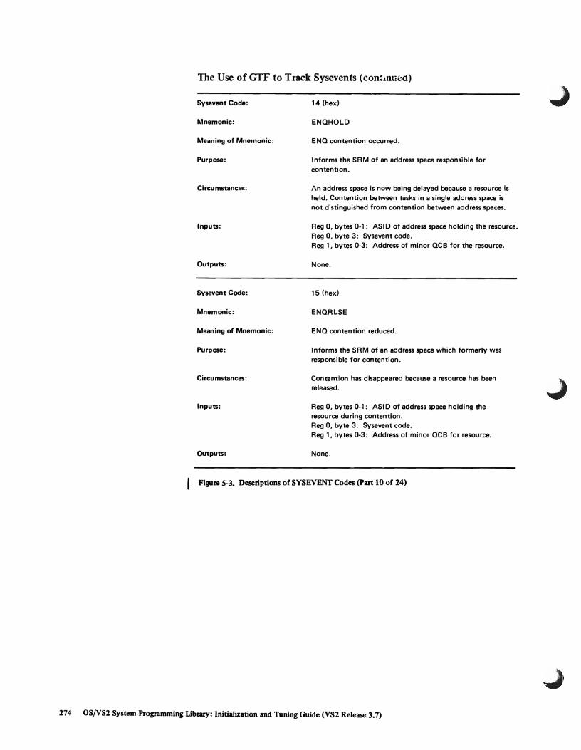
The Use ofGTF to Track Sysevents (con';inu~d)
Sysevent Code:
Mnemonic:
Meaning of Mnemonic:
Purpose:
Circumstances:
Inputs:
Outputs:
Sysevent Code:
Mnemonic:
Meaning of Mnemonic:
Purpose:
Circumstances:
Inputs:
Outputs:
14 (hex)
ENQHOLD
ENQ contention occurred.
Informs the SRM of an address space responsible for contention.
An address space is now being delayed because a resource is held. Contention between tasks in a single address space is not distinguished from contention between address spaces.
Reg 0, bytes 0-1: ASID of address space holding the resource. Reg 0, byte 3: Sysevent code. Reg 1, bytes 0-3: Address of minor QCB for the resource.
None.
15 (hex)
ENQRLSE
ENQ contention reduced.
Informs the SRM of an address space which formerly was responsible for contention.
Contention has disappeared because a resource has been released.
Reg 0, bytes 0-1: ASIO of address space holding the resource during contention. Reg 0, byte 3: Sysevent code. Reg 1, bytes 0-3: Address of minor QCB for resource.
None.
Figure 5-3. Descriptions of SYSEVENT Codes (part 10 of 24)
274 OS/VS2 System Programming Library: Initialization and Tuning Guide (VS2 Release 3.7)

L
The Use of GTF to Track Sysevents (continued)
Sysevent Code:
Mnemonic:
Meaning of Mnemonic:
Purpose:
Circu mstances:
Inputs:
Outputs:
Sysevent Code:
Mnemonic:
Meaning of Mnemonic:
Purpose:
Circumstances:
Inputs:
Outputs:
16 (hex)
RSMCNSTS
Real Storage Manager constants.
Supplies the SRM with the size of functioning real storage and the number of pages on the available frame queue, when the "available frame queue below limit" sysevent (code X'17')
is issued. Issued when a VARY Storage command is processed and when the system is initialized.
Reg 0, byte 3: Sysevent code. Reg 1; bytes 0-1: Number of pages of function ing real
storage. Reg 1, bytes 2-3: Number of pages that are on the
Available Frame Queue when the "available frame queue below limit" sysevent is issued.
None.
17 (hex)
AVQLOW
Available frame queue below limit.
Notifies the SRM that the number of real pages on the available frame queue has dropped below predefined limits.
Issued whenever allocation of a real page frame causes the number left on the available frame queue to drop below one of the predefined limits.
Reg 0, byte 3: Sysevent code. Reg 1, byte 3: X'01' if the number of real pages on the
available frame queue has dropped below the limit. X'02' if the number of real pages on the available frame queue has dropped to zero. X'03' if a page fault occurs and there are no pages on the available frame queue.
None.
I Figure 5-3. Descriptions ofSYSEVENT Codes (part 11 of 24)
Part 5: System Performance Factors 275

The Use ofGTF to Track Sysevents (continued)
Sysevent Code:
Mnemonic:
Meaning of Mnemonic:
Purpose:
Circumstances:
Inputs:
Outputs:
Sysevent Code:
Mnemonic:
Meaning of Mnemonic:
Purpose:
Circumstances:
Inputs:
Outputs:
18 (hex}
AVOOK
Available frame queue above limit.
Notifies the SRM that the number of real pages on the available frame Queue has risen above a predefined limit.
Is issued whenever un allocation of a real page frame causes the number left on the available frame queue to rise above the predefined limit. This sysevent is issued only when the number of real pages rises above the predefined limit after the "available frame queue below limit" sysevent (code 17}
was issued.
Reg 0, byte 3: Sysevent code.
None.
19 (hex}
SOALOW
Unallocated SOA below threshold.
Indicates that the amount of unallocated virtual SOA has dropped below one of two predefined thresholds.
Virtual Storage Manager has just satisfied an SOA allocation request which resulted in the amount of unallocated SOA dropping below one of the two predefined thresholds.
Reg 0, byte 3: Sysevent code. Reg 1, byte 3: Contains X'01' if first (less serious} threshold
is passed; X'02' if second threshold is passed.
None
I Figure 5·3. Descriptions of SYSEVENT Codes (part 12 of 24)
276 OS!VS2 System Programming Libra:ry: Initialization and Tuning Guide (VS2 Release 3.7)

The Use ofGTF to Track Sysevents (continued)
Sysevent Code:
Mnemonic:
Meaning of Mnemonic:
Purpose:
Circumstances:
Inputs:
Outputs:
Ssysevent Code:
Mnemonic:
Meaning of Mnemonic:
Purpose:
Circumstances:
Inputs:
Outputs:
1A
SQAOK
Unallocated SQA above threshold.
Indicates that the amount of unallocated SQA has risen above one of two predefined thresholds.
Virtual Storage Manager has just handled an SQA unallocation request which resulted in the amount of unallocated SQA rising above one of the two predefined thresholds.
Reg 0, byte 3: Sysevent code. Reg 1, byte 3: Contains X'01' if first (less serious) threshold
has passed; X'02' if second threshold passed.
None.
1B
ASMCNSTS
Auxiliary storage constants.
Allows Auxiliary Storage Manager (ASM) to communicate the size of paging space on direct access.
Note: The discovery of individual defective slots will not result in the. issuing of the ASMCNSTS sysevent.
Is issued at system initialization time.
Reg 0, byte 3: Sysevent code. Reg 1, bytes 0-3: Contains a pointer to a list of fullword
UCB addresses that point to those UCBs whose devices contain one or more data sets which are part of the paging set. The first fullword contains the number of entry UCB addresses that follow.
None.
I Figure 5-3. Descriptions of SYSEVENT Codes (part 13 of 24)
Part 5: System Performance Factors 277

The Use of GTF to Track Sy~veats (continued)
Sysevent Code:
Mnemonic:
Meaning of Mnemonic:
Purpose:
Inputs:
Outputs:
Sysevent Code:
Mnemonic:
Meaning of Mnemonic:
Purpose:
Circumstances:
Inputs:
Outputs:
1C
DEVALLOC
Device allocation request.
Provides SRM with necessary data for making a device allocation decision where two or more candidates exist.
Reg 0, bytes 0-1: ASI D or zero. Reg 0, byte 3: Sysevent code.
Reg 1, bytes 0-3: Address of a list of three full-word addresses, The first points to a list of candidate UCB addresses. The second points to a list of addresses of UCBs already allocated to the requesting jobstep. The third points to a two-word return area.
The first word in the list of candidate UCBs contains a count of the number of candidates in the list. The first word of the list of addresses of already allocated UCBs contains a count of the number of addresses in the list. All input and output data areas must be fixed.
Reg 1, bytes 0-3: Contains the same address present at input.
Return area 1st word: Contains the address of the candidate list entry which was selected.
Reg 15, byte 3: Contains X'OO' if allocation selection was successfully made; X'OS' if it was unsuccessful.
1D
CONFIGCH
System configuration change.
Indicates that resources are to be removed from or added to the system.
The system operator has issued a VARY (online or offline) command for a channel, path, or CPU.
Reg 0, byte 3: Sysevent code. Reg 1, bytes 0-3: Points to the SMF type 22 record that
describes the configuration change.
None.
Figure 5-3. Descriptions of SYSEVENT Codes (part 14 of 24)
278 OS/VS2 System Programming Library: Initialization and Tuning Guide (VS2 Release 3.7)

L The Use ofGTF to Track Sysevents (continued)
Sysevent Code:
Mnemonic:
Meaning of Mnemonic:
Purpose:
Circumstances:
Inputs:
Outputs:
Sysevent Code:
Mnemonic:
Meaning of Mnemonic:
Purpose:
Circu mstances:
Inputs:
Outputs:
1E
VERIFYPG
Verify performance group.
To determine if the input Performance Group Number is currently "known" to the SRM, and to indicate the default value if the input number is not "known".
LOGON or the Converter/Interpreter has received a Performance Group Number which needs verification.
Reg 0, bytes 0-1: AS I 0 or zero. Reg 0, byte 3: Sysevent code. Reg 1, byte 3: Performance Group Number.
Reg 1, byte 2: Contains 0 if the input number is valid. If the input number is not valid, it contains 1 if the ASIO belongs to a non-TSO user, or 2 if the ASIO belongs to a TSO user.
1F
RESETPG
Reset performance group.
Resets the Performance 'Group Number associated with an ASIO.
The system operator has· entered a RESET jobname, PERFORM=nn command.
Reg 0, bytes 0-1: ASIO. Reg 0, byte 3: Sysevent code. Reg 1, byte 3: New petformance group number.
Reg 1, byte 2: Contains X'OO' if the RESET request was honored, X'04' if the new Performance Group Number is not valid, or X'OS' if the ASI D is not currently assigned.
I Figure 5-3. Descriptions ofSVS'EVENT Codes (part 15 of 24)
Put 5: System Performance Factors 279
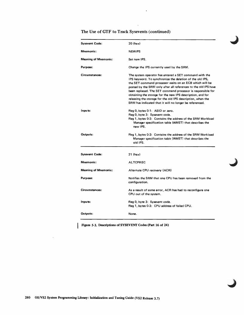
The Use ofGTF to Track Sysevents (continued)
Sysevent Code:
Mnemonic:
Meaning of Mnemonic:
Purpose:
Circumstances:
Inputs:
Outputs:
Sysevent Code:
Mnemonic:
Meaning of Mnemonic:
Purpose:
Circumstances:
Inputs:
Outputs:
20 (hex)
NEWIPS
Set new IPS.
Change the IPS currently used by the SRM.
The system operator has entered a SET command with the IPS keyword. To synchronize the deletion of the old IPS, the SET command processor waits on an ECB which will be posted by the SRM only after all references to the old IPS have been replaced. The SET command processor is responsible for obtaining the storage for the new IPS description, and for releasing the storage for the old IPS description, when the SRM has indicated that it will no longer be referenced.
Reg 0, bytes 0-1: ASIO or zero. Reg 0, byte 3: Sysevent code. Reg 1, bytes 0-3: Contains the address of the SRM Workload
Manager specification table (WMST) that describes the new IPS.
Reg 1, bytes 0-3: Contains the address of the SRM Workload Manager specification table (WMST) that describes the old IPS.
21 (hex)
ALTCPREC
Alternate CPU recovery (ACR)
Notifies the SRM that one CPU has been removed from the configuration.
As a result of some error, ACR has had to reconfigure one CPU out of the system.
Reg 0, byte 3: Sysevent code. Reg 1, bytes 0-3: CPU address of failed CPU.
None.
I Figure 5-3. Descriptions of SYSEVENT Codes (part 16 of 24)
280 OS!VS2 System Programming Library: Initialization and Tuning Guide (VS2 Release 3.7)
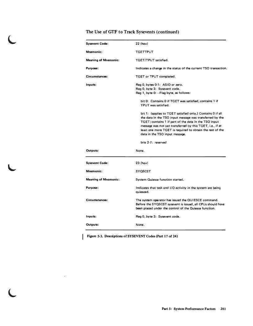
L
L
The Use ofGTF to Track Sysevents (continued)
Sysevent Code:
Mnemonic:
Meaning of Mnemonic:
Purpose:
Circumstances:
Inputs:
Outputs:
Sysevent Code:
Mnemonic:
Meaning of Mnemonic:
Purpose:
Circumstances:
Inputs:
Outputs:
22 (hex)
TGETTPUT
TGET/TPUT satisfied.
Indicates a change in the status of the current TSO transaction.
TGET or TPUT completed.
Reg 0, bytes 0-1: AS I D or zero. Reg 0, byte 3: Sysevent code. Reg 1, byte 0: - Flag byte, as follows:
bit 0: Contains 0 if TGET was satisfied; contains 1 if TPUT was satisfied.
bit 1: (applies to TGET satisfied only.) Contains 0 if all the data in the TSO input message was transferred by the TGET; contains 1 if part of the data in the TSO input message was not yet transferred by this TGET, i.e., if at least one more TGET is required to obtain the rest of the data in the TSO input message.
bits 2-7: reserved
None.
23 (hex)
SYQSCST
System Quiesce function started.
I ndicates that task and I/O activity in the system are being quiesced.
The system operator has issued the QU I ESCE command. Before the SYQSCST sysevent is issued, all CPUs should have been placed under the control of the Quiesce function.
Reg 0, byte 3: Sysevent code.
None.
Figure 5-3. Descriptions of SYSEVENT Codes (part 17 of 24)
Part 5: System Performance Factors 281

The Use of GTF to Track Sysevents (continued)
Sysevent Code:
Mnemonic:
Meaning of Mnemonic:
Purpose:
Circumstances:
Inputs:
Outputs:
Sysevent Code 25 (hex)
24 (hex)
SYQSCCMP
System Quiesce function completed.
Indicates that task and 1/0 activity in the system are being resumed.
When the system has been quiesced, the operator has pushed the START button.
Reg 0, byte 3: Sysevent code.
None.
This code is not used.
I Figure 5-3. Descriptions of SYSEVENT Codes (Part 18 of 24)
282 OS/VS2 System Programming Library: Initialization and Tuning Guide (VS2 Release 3.7)

L
L
The Use ofGTF to Track Sysevents (continued)
Sysevent Code:
Mnemonic:
Meaning of Mnemonic:
Purpose:
Circumstances :
Inputs:
Outputs:
26 (hex)
REOSERVC
Request .for service data.
Permits service-related data to be obtained for a given address space from the SR M.
Note: This sysevent is intended for use by SMF only because the related data fields in the OUSB and OUKB are reset to zero.
SMF will issue REOSERVC during job/session termination. TSO TIME command will also use the REOSERVC sysevent to obtain service data. The REOSERVC sysevent must be issued prior to the JOBTERM sysevent (code 9), because the address space data is reset upon receipt of JOBTERM.
The output area does not have to be fixed, and the issuer is not required to be authorized.
Reg 0, bytes 0-1: ASID or zero. Reg 0, byte 3: Sysevent code. Reg 1, bytes 0-3: Contains address of a 3-word area where
the service data is to be stored.
Service data supplied by SRM:
In the case of a TSO address space,the 3-word area contains:
Word 1 - Total service for the job. Word 2 - Total transaction active time. Word 3 - bytes 0-1: Performance group number last
assigned to the address space. Bytes 2-3: Total number of transactions.
In the case of a non-TSO address space, the 3-word area contains:
Word 1 - Total service for the session. Word 2 - Total active time for all transactions. Word 3 - bytes 0-1: Performance group number last
assigned to the address space. Bytes 2-3: Zeros.
Reg 15, byte 3: Contains X'04' if data was lost due to accumulation control block error; X'OO' otherwise.
I Figure 5-3. Descriptions of SYSEVENT Codes (part 19 of 24)
Part 5: System Performance Factors 283

The Use of GTF to Track Sysevents (continued)
Sysevent Code:
Mnemonic:
Meaning of Mnemonic:
Purpose:
Circumstances:
Inputs:
Outputs:
Sysevent Code: 28 (hex)
27 (hex)
REQPGDAT
Request by SMF for job paging data.
Permits SMF to obtain paging data for a given address space from the SRM.
Note: This sysevent is intended only for use by SMF because the related data fields in the OUSB and the OUXB are reset to zero on readouts. I f requested by another caller, the data would be unavailable to SMF.
SMF issues REQPGDAT during step termination. The REQPGDAT sysevent must be issued prior to the JOBTERM sysevent (code 9) because the address space data is reset upon receipt of JOBTERM.
Reg 0, bytes 0-1: ASID or zero. Reg 0, byte 3: Sysevent code. Reg 1, bytes 0-3: Contains the address of a 9-word area where
the paging data is to be stored.
Paging data supplied by SRM:
Word 1 - Count of non-VIO page-ins. Word 2 - Count of non-VIO page-outs. Word 3 - Count of non-VIO reclaims. Word 4 - Count of VIO page-ins. Word 5 - Count of VIO page-outs.
Word 6 - Count of VIO reclaims. Word 7 - Count of pages swapped in. Word 8 - Count of pages swapped out. Word 9 - Count of swapouts.
Reg 15, byte 3: Indicates whether data was successfully returned (00), or not (04).
This code is not used.
Figure 5-3_ Descriptions of SYSEVENT Codes (part 20 of 24)
284 OS/VS2 System Programming Library: Initialization and Tuning Guide (VS2 Release 3.7)

L
L
The Use of GTF to Track Sysevents (continued)
Sysevent Code:
Mnemonic
Meaning of Mnemonic:
Purpose:
Circumstances:
Inputs:
Outputs:
Sysevent Code:
Mnemonic:
Meaning of Mnemonic:
Purpose:
Circumstances :
Inputs:
Outputs:
29 (hex)
DONTSWAP
Address Space is now not swappable.
Indicates to the SRM that the issuing address space must not be swapped until further notice.
Application dependent.
Reg 0, bytes 0-1: ASI D of issuing address space, or zero. Reg 0, byte 3: Sysevent code.
Reg 1, byte 3: Contains X'04' if request is not for the current address space; contains X'OO' if the request to mark the address space as non-swappable was honored; contains X'OS' if request was not authorized, or if the outstanding count of DONTSWAP requests (code 29) has reached its maximum value.
Note: Nonswappable status is reset at the time of attach by initiator (code OA) and detach by initiator (code OB). That is, nonswappable status it not carried across job steps.
2A
OKSWAP
Memory now swappable.
Indicates to the SRM that the issuing address space may now be swapped.
Application dependent.
Reg 0, bytes 0-1: ASI D of issuing address space, or zero. Reg 0, bYte 3: Sysevent code.
Reg 1, byte 3: Contains X'04' if request is not for the current address space; contains X'OO' if the request to mark the address space as swappable was honored; contains X'OS' if request was not authorized.
I Figure 5-3. Descriptions of SYSEVENT Codes (Part 21 of 24)
Part 5: System Performance Factors 285

The Use of GTF to Track Sysevents (continued)
Sysevent Code:
Mnemonic:
Meaning of Mnemonic:
Purpose:
Circumstances:
Inputs:
Outputs:
Sysevent Code:
Mnemonic:
Meaning of Mnemonic:
Purpose:
Circumstances:
Inputs:
Outputs:
2B
REQSWAP
Request to swap out address space.
A particular address space is required to be swapped out.
An address space is being requested to release the real storage frames it currently occupies. At the time of the subsequent lwap-in, the Real Storage Manager re-allocates real storage frames to the swapped-in address space.
Reg 0, bytes 0-1: ASIO or zero. Reg 0, byte 3: Sysevent code. Reg 1, bytes 0-3: Address of ECB to be posted.
Reg 1, byte 3: Contains X'OO' if the swap-out request was honored; X'04' if the request was ignored because of the non-swappable status of the indicated address space; contains X'OS' if address space is being swapped out.
2C
BRINGIN
Request to swap in address space.
A partiailar address space is required to be swapped in.
The current job in this address space has been canceled. If BRINGIN were not issued, an address space that had been swapped out because of a shortage might be kept out until the shortage had been relieved.
Reg 0, bytes 0-1: ASIO or zero. Reg 0, byte 3: Sysevent code.
Reg 1, byte 3: Contains X'OO' if the swap-in request was honored; X'OS' if address space is currently in the procelS of being swapped.
I Figure. 5-3. Descriptions of SYSEVENT Codes (Part 22 of 24)
286 OS!VS2 System Programming Library: Initialization and TUBing Guide(VS2 Release 3.7)

The Use of GTF to Track Sysevents (continued)
Sysevent Code:
Mnemonic:
Meaning of Mnemonic:
Purpose:
Circumstances:
Inputs:
Outputs:
Sysevent Code:
Mnemonic:
Meaning of Mnemonic:
Purpose:
Circumstances:
Inputs:
Outputs:
2D
WKLDINIT
Workload activity measurement initialization.
Permits MF/l to inform the SRM to start collecting workload activity data by Performance Group Period (PGP), and provides the buffer used for data collection.
MF/l workload activity measurements are being activated.
Reg 0, bytes 0-1: ASID or zero. Reg 0, byte 3: Sysevent code. Reg 1, bytes 0-3: The address of a global data collection
buffer.
Reg 1, bytes 0-3: 0 if data collection is successfully initialized.
Reg 15, byte 3: X'OO' if the request was honored, and no exception conditions were found; X'08' if a request to start workload activity data collection was rejected because of an incorrect buffer size; X'20' if data collection is already active.
2E
WKLDCOLL
Workload activity measurement collection.
Permits MF/1 to retrieve a copy of the data collected since the previous WKLDCOLL or WKLDINIT sysevent (code 2Dl. If, however, the IPS has changed, MF/l will issue the WKLDTERM sysevent (code 2Fl. followed by WKLDINIT to provide a different data collection area.
End of an MF/l measurement interval.
Reg 0, bytes 0-1: ASID or zero. Reg 0, byte 3: Sysevent code. Reg 1, bytes 0-3: The address of a fixed buffer into which
the collected workload activity measurements are to be copied.
Reg 1, bytes 0-3: Unchanged Reg 15, byte 3: X'OO' if the request was honored, and no
exception conditions were found; X'Q4' if previously started workload activity data collection has been stopped because of an I PS change; X'40' if the data collection buffer has not been established.
I Figure S-3. Descriptions of SYSEVENT Codes (part 23 of 24)
Part 5: System Performance Factors 287

The Use of GTF to Track Sysevents (continued)
Sysevent Code:
Mnemonic:
Meaning of Mnemonic:
Purpose:
Circumstances:
Inputs:
Outputs:
Sysevent Code:
Mnemonic:
Purpose:
Inputs:
Outputs:
2F
WKLDTERM
Workload activity measurement termination.
Permits MF/1 to inform the SRM to stop collecting workload activity data, and retrieve the buffer used for data collection.
MF/1 workload activity measurements are being terminated, or an I PS change has occurred.
Reg 0, bytes 0-1: AS I D or zero. Reg 0, byte 3: Sysevent code. Reg 1, bytes 0-3: Zero.
Reg 1, bytes 0-3: The address of the global, fixed, workload activity data collection buffer that is no longer being used by the SRM.
Reg 15, byte 3: X'OO' if the request was honored, and no exception conditions were found; X'40' if the data collection buffer has not been established.
30 (hex)
None
Issued by the SRM itself in order to do full analysis processing, or to invoke its control routine immediately without waiting for a sysevent issued by another component.
Reg 0, bytes 0-1: AS I D or zero. Reg 0, byte 3: Sysevent code. Reg 1, bytes 1-3: Address of system resource block under
which this sysevent is issued.
None.
I Figure 5-3. Descriptions of SYSEVENT Codes (part 24 of 24)
288 OS!VS2 System Programming Library: Initialization and Tuning Guide (VS2 Release 3.7)
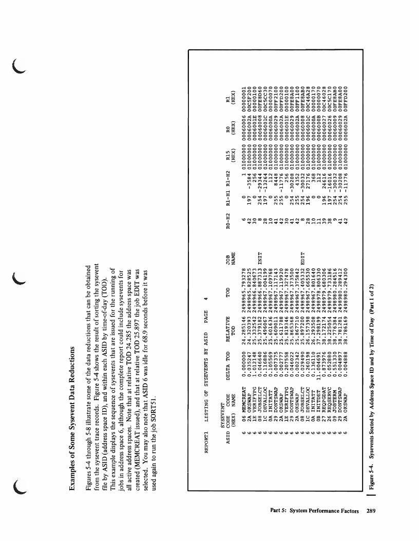
~ v.
~ ~ l 0-a ~ (') ('I)
'rl .. (')
~ '"
r r
Examples of Some Sysevent Data Reductions
Figures 5-4 through 5-8 illustrate some of the data reductions that can be obtained from the sysevent trace records. Figure 5-4 shows the result of sorting the sysevent fIle by ASID (address space ID), and within each ASID by time-of-day (TOD). This example displays the sequence of sysevents that are issued for the running of jobs in address space 6, although the complete report could include sysevents for all active address spaces. Note that at relative TOD 24.285 the address space was created (MEMCREAT issued), and that at relative TOD 25.897 the job EDIT was selected. You may also note that ASID 6 was idle for 68.9 seconds before it was used again to run the job SORT5l.
REPORTI LISTING OF SYSEVENTS BY ASID PAGE 4
SYSEVENT ASID CODE CODE DELTA TOD RELATIVE TOD
(HEX) NAME TOD
6 06 MEMCREAT 0.000000 24.285146 2498965.793278 6 2A OKSWAP 0.035247 24.320393 2498965.828525 6 IE VERIFYPG 1. 012148 25.332542 2498966.840673
JOB NAME
6 08 JOBSELCT 0.046640 25.379182 2498966.887313 INIT 6 lC DEVALLOC 0.116886 25.496067 2498967.004199 6 OA INITATT 0.105569 25.601636 2498967.109768 6 29 DONTSWAP 0.007375 25.609011 2498967.117143 6 2A OKSWAP 0.002777 25.611788 2498967.119920 6 IE VERIFYPG 0.207558 25.819346 2498967.327478 6 29 DONTSWAP 0.046022 25.865368 2498967.373500 6 2A OKSWAP 0.002342 25.867710 2498967.375842 6 08 JOBSELCT 0.029490 25.897200 2498967.405332 EDIT 6 lC DEVALLOC 0.260198 26.157398 2498967.665530 6 OA INITATT 0.136110 26.293508 2498967.801640 6 OB INITDET 11.004691 37.298199 2498978.806330 6 27 REQPGDAT 0.873976 38.172174 2498979.680306 6 26 REQSERVC 0.052880 38.225054 2498979.733186 6 09 JOB TERM 0.551330 38.776384 2498980.284516 6 29 DONTSWAP 0.004897 38.781281 2498980.289412 6 2A OKSWAP 0.004888 38.786169 2498980.294300
~ I Figure 5-4. Sysevents Sorted by Address Space ID and by Time of Day (Part 1 of 2)
r
RO-H2 RI-Hl RI-H2 R15 RO Rl (HEX) (HEX) (HEX)
6 0 1 01000000 00060006 00000001 42 197 -3584 01000000 0006002A 00C5F200 30 0 256 01000000 0006001E 00000100
8 254 -29344 01000000 00060008 00FE8D60 28 197 -13264 01000000 0006001C 00C5CC30 10 0 112 01000000 0006000A 00000070 41 255 8448 01000000 00060029 00FF2100 42 255 -11776 01000000 0006002A 00FFD200 30 0 256 01000000 0006001E 00000100 41 254 -30208 01000000 00060029 00FE8AOO 42 255 4352 01000000 0006002A 00FFI100
8 254 -30032 01000000 00060008 00FE8ABO 28 196 27176 01000000 0006001C 00C46A28 10 0 368 01000000 0006000A 00000170 11 0 112 01000000 0006000B 00000070 39 196 24616 01000000 00060027 00C46028 38 197 -16016 01000000 00060026 00C5C170
9 254 -30032 00000000 00060009 00FE8ABO 41 254 -30208 01000000 00060029 00FE8AOO 42 255 -11776 01000000 0006002A 00FFD200

'" IC REPORT1 LISTING OF SYSEVENTS BY ASID PAGE 5 0
0 SYSEVENT til ASIO CODE CODE DELTA TOD RELATIVE JOB RO-H2 R1-H1 R1-H2 RO R15 R1
"< (HEX) NAME TOD TOD NAME (HEX) (HEX) (HEX) til
'" til Address 6 OB INITDET 0.229847 39.016016 2498980.524147 11 0 127 01000000 0006000B 0000007F '< IpBceis 6 09 JOBTERM 1.185431 40.201447 2498981.709579 9 254 -29344 00000000 00060009 00FE8D60 ... ... idle between 6 29 DONTSWAP 0.267263 40.468710 2498981.976842 41 254 -29440 01000000 00060029 00FE8DOO '" MEMDEL a end 6 2A OK SWAP 0.004881 40.473591 2498981.981723 42 255 4352 01000000 0006002A 00FF1100
i MEMCREAT 7 7 254 -2 2 0100 000 060007 00FE8C04 for - 69 IIC'S. 6 06 MEMCREAT 68.936987 110.197651 2499051.705783 6 0 1 01000000 00060006 00000001
6 2A OKSWAP 0.038446 110.236097 2499051.744229 42 197 -3584 01000000 0006002A 00C5F200 a 6 IE VERIFYPG 1.033204 111.269301 2499052.777433 30 0 256 01000000 0006001E 00000100 a 6 08 JOBSELCT 0.044454 111.313755 2499052.821887 INIT 8 254 -29448 01000000 00060008 00FE8CF8 5' 6 1C DEVALLOC 0.116931 111.430686 2499052.938818 28 197 -13264 01000000 0006001C 00C5CC30 IJQ
t:: 6 OA INITATT 0.105535 111.536221 2499053.044353 10 0 112 01000000 0006000A 00000070 0' 6 29 DONTSWAP 0.007381 111.543602 2499053.051734 41 255 8448 01000000 00060029 00FF2100
~ 6 2A OKSWAP 0.003306 111.546908 2499053.055040 42 255 -11776 01000000 0006002A 00FFD200 6 IE VERIFYPG 0.208044 111.754952 2499053.263084 30 0 256 01000000 0006001E 00000100 - 6 29 DONTSWAP 0.327362 112.082314 2499053.590446 41 254 -30464 01000000 00060029 OOFE8900 e. 6 2A OKSWAP 0.002291 112.084605 2499053.592737 42 255 4352 01000000 0006002A 00FF1100 ct.
I!!. 6 08 JOBSELCT 0.014430 112.099035 2499053.607167 SORT51 8 254 30256 01000000 00060008 OQpE89DO N' 6 lC DEVALLOC 0.554243 112.653278 2499054.161409 28 196 26648 01000000 0006001C 00C46818 0> 6 lC DEVALLOC 0.374354 113.027631 2499054.535763 28 196 26648 01000000 0006001C 00C46818 ct. 0 6 lC DEVALLOC 0.196342 113.223973 2499054.732105 28 196 26648 01000000 0006001C 00C46818 ::I
§ 6 1C DEVALLOC 0.256034 113.480007 2499054.988139 28 196 26648 01000000 0006001C 00C46818 c::>. 6 lC DEVALLOC 0.203693 113.683700 2499055.191832 28 196 26648 01000000 0006001C 00C46818 o-l 6 lC DEVALLOC 0.169903 113.853603 2499055.361735 28 196 26648 01000000 0006001C 00C46818 r:: 6 OA INITATT 0.150534 114.004137 .2499055.512269 10 0 368 01000000 0006000A 00000170 ::I S" 6 OB INITDET 25.951629 139.955766 2499081.463898 11 0 112 01000000 0006000B 00000070
IJQ 6 27 REQPGDAT 3.094599 143.050365 2499084.558497 39 196 28000 01000000 00060027 00C46D60 ~ 6 lC DEVALLOC 3.306372 146.356737 2499087.864869 28 196 27944 01000000 0006001C 00C46D28 r:: is: 6 lC DEVALLOC 0.319020 146.675757 2499088.183889 28 196 27944 01000000 0006001C 00C46D28
'" ,-. 6 lC DEVALLOC 0.706039 147.381796 2499088.889928 28 196 27944 01000000 0006001C 00C46D28 -< 6 OA INITATT 0.247548 147.629344 2499089.137475 10 0 368 01000000 0006000A 00000170 In 6 OB INITDET 9.218179 156.847522 2499098.355654 11 0 112 01000000 0006000B 00000070 '" ~ 6 27 REQPGDAT 0.796571 157.644093 2499099.152225 39 196 24960 01000000 00060027 00C46180 '" 6 lC DEVALLOC 0.377081 158.021174 2499099.529305 28 196 24944 01000000 0006001C 00C46170 if 6 lC DEVALLOC 0.546341 158.567514 2499100.075646 28 196 24944 01000000 0006001C 00C46170 i£ 6 OA INITATT 0.285603 158.853117 2499100.361249 10 0 368 01000000 0006000A 00000170 IN 6 OC QSCEST 19.132159 177.985276 2499119.493408 12 -32768 o 01000000 0006000C 80000000 !...J '-' 6 OD QSCECMP 0.066583 178.051859 2499119.559991 13 0 o 00000000 0006000D 00000000
6 OF SWOUTCMP 0.373022 178.424881 2499119.933013 15 255 -32372 01000000 0006000F 00FF818C 6 13 RSTORCMP 0.860902 179.285784 2499120.793915 19 0 o 00000000 00060013 00000000 6 OB INITDET 5.067999 184.353783 2499125.861914 11 0 112 01000000 0006000B 00000070 6 27 REQPGDAT 0.525064 184.878846 2499126.386978 39 196 25088 01000000 00060027 00C46200 6 lC DEVALLOC 0.734655 185.613501 2499127.121633 28 196 25848 01000000 0006001C 00C464F8 6 1C DEVALLOC 0.183022 185.796523 2499127.304655 28 196 25848 01000000 0006001C 00C464F8 6 lC DEVALLOC 0.188660 185.985183 2499127.493314 28 196 25848 01000000 0006001C 00C464F8 6 lC DEVALLOC 0.186157 186.171340 2499127.679471 28 196 25848 01000000 0006001C 00C464F8 6 lC DEVALLOC 0.190462 186.361802 2499127.869933 28 196 25848 01000000 0006001C 00C464F8 6 lC DEVALLOC 0.172484 186.534285 2499128.042417 28 196 25848 01000000 0006001C 00C464F8 6 OA INITATT 0.161511 186.695796 2499128.203928 10 0 368 01000000 0006000A 00000170 6 OC QSCEST 20.740748 207.436545 2499148.944676 12 -32768 o 01000000 0006000C 80000000 6 OD QSCECMP 0.077732 207.514277 2499149.022408 13 0 o 00000000 0006000D 00000000 6 OF SWOUTCMP 0.381616 207.895892 2499149.404024 15 253 30632 01000000 0006000F 00FD77A8
Figure 5-4. Sysevents Sorted by Address Space ID and by Time of Day (Part 2 of 2)
~ ~ \.,

"'CI
! U'I
ron '< S a "'CI ~ 0-a ~ " .. "!j
I'l ~ N ID ...
r r Figure 5-5 shows the number of times a particular sysevent was issued. It
gives both the mean time and the time distribution between successive issuances. Consider sysevent code 1 C (DEV ALLOC). This sysevent was issued 282 times (there are 281 time intervals between successive issuances). The mean time between such events was 4.26 seconds. The distribution also shows that 61.1 % of the intervals (60.1% + 0.3% + 0.7%) were within 0.5 seconds.
TIME BETWEEN SYSEVENTS OF SAME TYPE
COUNT M(REAL DELTA) CODE CODE REAL DELTA TOD <= <=
PERCENTS DELTA TOD(REAL DELTA) <= <= <= <= <= <= <= >
NAME DELTA 0.001 0.050 0.100 0.500 1.000 5.000 10.000 50.000 100.000 100.000
01 TIMEREXP 126 9.723068 0.0 0.0 0.0 0.0 0.0 0.0 99.2 0.7 0.0 0.0 03 NIOWAIT 18 65.380090 0.0 0.0 0.0 0.0 0.0 11.1 11.1 38.8 5.5 33.3 04 USERRDY 16 67.759794 0.0 0.0 0.0 0.0 0.0 6.2 12.5 43.7 0.0 37.5 06 MEMCREAT 2 45.301654 0.0 0.0 0.0 0.0 0.0 50.0 0.0 0.0 50.0 0.0 07 MEMDEL 0 0.000000 0.0 0.0 0.0 0.0 0.0 0.0 0.0 0.0 0.0 0.0 08 JOBSELCT 23 51.193591 0.0 0.0 0.0 4.3 8.6 13.0 0.0 34.7 30.4 8.6 09 JOBTERM 20 59.802141 0.0 0.0 0.0 0.0 4.9 9.9 0.0 44.9 29.9 9.9 OA INITATT 93 12.884177 0.0 0.0 0.0 1.0 7.5 13.9 35.4 40.8 1.0 0.0 OB INITDET 91 13.186660 0.0 0.0 0.0 2.1 5.4 12.0 35.1 43.9 0.0 1.0 OC QSCEST 36 28.502030 0.0 16.6 5.5 0.0 0.0 2.7 8.3 52.7 11.1 2.7 OD QSCECMP 42 28.666021 0.0 9.5 9.5 0.0 2.3 4.7 7.1 57.1 4.7 4.7 OF SWOUTCMP 41 29.362830 0.0 0.0 0.0 19.5 2.4 2.4 7.3 56.0 7.3 4.8 13 RSTORCMP 41 25.037034 0.0 9.7 0.0 12.1 4.8 4.8 14.6 41.4 9.7 2.4 14 ENQHOLD 9 76.807824 0.0 0.0 0.0 0.0 0.0 11.1 22.2 55.5 0.0 11.1 15 ENQRLSE 9 76.792479 0.0 0.0 0.0 0.0 0.0 11.1 22.2 55.5 0.0 11.1 17 AVQLOW 5 216.231253 0.0 0.0 0.0 0.0 0.0 0.0 19.9 39.9 19.9 19.9 18 AVQOK 5 216.232278 0.0 0.0 0.0 0.0 0.0 0.0 19.9 39.9 19.9 19.9 lC DEVALLOC 281 4.263045 0.0 0.7 0.3 (60.D 7.4 6.4 11. 7 12.8 0.3 0.0 IE VERIFYPG 23 51.175377 0.0 0.0 0.0 13.0 4.3 8.6 0.0 34.7 30.4 8.6 26 REQSERVC 20 60.007462 0.0 0.0 0.0 0.0 4.9 9.9 0.0 44.9 29.9 9.9 27 REQPGDAT 90 13.332241 0.0 0.0 0.0 3.3 3.3 14.4 33.3 44.4 0.0 1.1 29 DONTSWAP 47 25.759186 0.0 0.0 0.0 14.8 21.2 23.4 0.0 21. 2 14.8 4.2 2A OKSWAP 50 24.213887 0.0 5.9 0.0 15.9 17.9 21.9 0.0 19.9 13.9 3.9 30 SRB 114 10.826754 0.0 0.8 0.0 8.7 7.0 17.5 9.6 56.1 0.0 0.0
I Figure 5-5. Time Distribution Between Sysevents of Same Type
r

t.j o,a t.j
o t/}
"< t/} t.j
t/}
i 3
~ 3 3 ~.
~ ~ [ ~ ., g. ::; ., 8-~ ::; ~.
~ s: II>
'< t/} t.j
:::c II>
[ <H
2
The report in Figure 5-6 shows the distribution of swap out time. It was produced by selecting records from the sysevent trace data only for code OD (QUIESCE COMPLETED) and code OF (SWAPOUT COMPLETED). There were 36 code-OD records and all 36 resulted in completed swapouts. The mean time to complete a swapout (the time between QUIESCE COMPLETED and SWAPOUT COMPLETED) was 0.27 seconds. Note that 66.6% of the swapouts completed within 0.30 seconds. Note also that 11 % of the swapouts took longer than 0.5 second.
DISTRIBUTION OF SWAP OUT TIMES
M(COD,OF) PERCENTS TRO(COD,OF) COUNT CODE 00
COUNT CODE OF
COUNT CODE 00 SWAP COMPLETE
COUNT CODE 00 NO
TRO <= <= <= <= <= <= <= <= <= <= <= <= 0_010 0.030 O_OSO 0_100 0_300 0_400 O.SOO 0.600 0_700 0_800 0.900 1.000
~ 36
Number of code 00 records (quiesce completed)
SWAP
~ o
Number of code OF records that completed swapout (swapout completed)
~ 0_0
Mean time to complete a swapout
Figure 5-6_ Distribution of Time Needed to Complete a Swapout
'-
0.0 0_0 0_0 ~16_6 S.S~ 0_0 0.0 0_0 0_0
Number of swapouts Number of swapouts that completed within that took longer than 0.3 seconds 0.5 seconds
'-;
Number of Seconds
Lo~oJ 0_0
'-

Figure 5·7 depicts a listing that shows real frame shortages, as indicated by occurrences of AVQLOW (code X'I7') and AVQOK (code X'18') records sorted by relative time of day. The coded numeral 'I' in the last column indicates an AVQLOW non·critical threshold, and the numeral '2' indicates an AVQLOW critical threshold. Note that at relative TOD 0.0 a non·critical AVQLOW occurred, followed by five critical A VQLOWs. Finally at relative time 0.65 an A VQOK occurred, signifying a temporary end to the real frame shortage.
LIST OF SYSTEM RECORDS
SYSEVENT CODE CODE DELTA TOD RELATIVE Rl,B3 (HEX) NAME TOD (indicator)
17 AVQLOW 0.000000 0.000000 1 17 AVQLOW 0.139316 0.139316 2 17 AVQLOW 0.045019 0.184335 2 17 AVQLOW 0.041238 0.225573 2 17 AVQLOW 0.013628 0.239201 2 17 AVQLOW 0.402581 0.641782 2 18 AVQOK 0.010584 0.652366 17 AVQLOW 0.660104 1. 312469 1 17 AVQLOW 0.460672 1.773141 2 18 AVQOK 0.007536 1. 780677 17 AVQLOW 5.513137 7.293814 1 17 AVQLOW 0.262811 7.556625 2 18 AVQOK 0.005968 7.562593 17 AVQLOW 0.275185 7.837777 1 18 AVQOK 0.927716 8.765494
I Figure 5·7. Instances of Real Frame Shortages, Distributed by Time of Day
DISTRIBUTION OF
COUNT COUNT COUNT C17 C17C C18
4 7 4
A reasonable question to be asked is: How long did the real frame shortage last? This question can be answered by means of pencil, paper, and the report in Figure 5-7, or by use of the reduction program to produce the report shown in Figure 5-8. In Figure 5·8 four non-critical A VQLOWs were issued and seven critical A VQLOWs were Issued. The average amount of time spent at A VQLOW was approximately 0.58 seconds, with all durations being less than 1 second. During this analysis period the total time spent at AVQLOW was 2.3 seconds_
AVQLOW TIMES
M(C17-C18) PERCENTS AVQTIME(C17-C18) MAX T(C17-CI8) AVQTIME < = < = < = < = <= < = > RELATIVE AVQTIME (AVERAGE) 0.1 0.3 0.5 0.7 1 300 300 TOD (TOTAL)
(0.5793) 0.0 25.0 25.0 25.0 25.0 0.0 0.0 8.765494 (2.3171)
I Figure 5-8. Distribution of Real Frame Shortages
Part 5: System Performance Factors 293

TCAM Tuning Considerations
This section describes special considerations for page fixing TCAM in areas containing TCAM CSECTs, modules, and control blocks.
It covers three topics related to page fixing and page faults:
• Packaging the MCP to Minimize Page Fixes and Page Faults
• Coding INTRO Operands to Minimize Fixed Pages
• Ordering of OPENs to Minimize Fixed Pages for LCBs and SCBs.
For additional performance guidelines on TCAM, refer to the OS/VS2 TCAM Programmer's Guide and the OS/VS TCAM User's Guide (GC30-2025) which give guidelines on efficient section ordering of the Message Control Program (MCP) and explanations of space utilization caused by selecting certain TCAM options. These guidelines and explanations should help minimize the number of fixed pages required in the TCAM system, and also minimize the number of page faults.
Packaging the MCP to Minimize Page Fixes and Page Faults
The parmlib member, IEAPAKOO, can be used to group TCAM modules in the pageable link pack area (PLP A). The user can reduce page faults by grouping modules that refer to each other during execution. Suggested groupings are:
• TCAM open modules
• TCAM close modules
• TCAM error recovery modules.
In addition, TCAM operator control modules can be grouped in the PLPA according to those that are most often used. For further information on IEAPAKOO, see "Part 2: System Initialization - PARMLIB Members" in this manual. For information on the PLPA, see the performance topic, "The Pageable Link Pack Area: Its Advantages and Uses" in Part 5. The following control blocks and modules will be fixed by TCAM and should be grouped by the linkage editor ORDER control statement as described below:
• Control blocks:
Assembled in the MCP -Address Vector Table (AVT) Data Control Blocks (DeBs) Device Characteristics Table Invitation Lists Option Tables Queue Control Blocks (QCBs) Station Control Blocks (SCBs) Terminal Entries Terminal Name Table (TNT)
CSECT MCP MCP IEDQSTCS MCP IEDQOPC, IEDQOPT IEDQQCBC IEDQSCBC IEDQTRMC IEDQTNT
294 OS!VS2 System Programming Library: Initialization and Tuning Guide (VS2 Release 3.7)

L
L
Packaging the MCP to Minimize Page Fixes and Page Faults (continued)
Dynamically Acquired (via GETMAIN): Buffer Units Channel Program Blocks (CPBs) Dial SCBs Line Control Blocks (LCBs)
• Loaded modules:
Attention Handler Routine Channel End Appendage I/O Trace Table PCI Appendage Special Characters Table Start I/O Appendage
The module names for the TCAM routines listed above can be found in OS/VS2 TeAM Logic, SY30.2040).
The linkage editor ORDER control state-ment can be used to cause the TCAM MCP to be loaded on a page boundary and to group CSECTs of the MCP that are fIxed. The ORDER statement can also be used to group modules in the MCP according to their use. Section 4 of OS/VS2 TeAM Logic correlates TCAM modules to TCAM function in the MCP. The user can determine the order in which his MCP calls on TCAM modules and then use the ORDER statements to cause TCAM to order the MCP accordingly, thus reducing the number of page faults between execution of different modules. The following example shows how the ORDER statement can be used to group CSECTs and modules so that the number of page fIxes is minimized:
ORDER MCP (P) (P) requests page boundary alignment by the linkage editor.
ORDER IEDQQCBC
ORDER IEDQTNT
ORDER IEDQTRMC
ORDER IEDQOPT ) IEDQOPT and IEDQOPC are in the MCP only if the
ORDER IEDQOPC OPTION facility is used.
ORDER IEDQSTCS
ORDER IEDQSCBC
ORDER IEDAYZ ) IEDA YZ and IEDQKA02 are page fIxed only if TSO is included in a TCAM system running with an IBM
ORDER IEDQKA02 2701, 2702, or 2703 control unit.
ENTRY MCP
Part 5: System Performance Factors 295

Coding INTRO Operands to Minimize Fixed Pages
By carefully selecting operands of the INTRO macro instruction, the user can minimize the number of fixed pages required for the following if real storage size is critical:
• Station Control Blocks (SCBs).
• I/O Trace Table.
• Buffer Units.
• Channel Program Blocks (CPBs).
The pages for these control blocks are obtained and fixed during TCAM initialization.
The following operands of the INTRO macro instruction determine the number of pages that are fixed:
USEREG= UNITSZ=, KEYLEN= (See note below) LNUNITS= MSUNITS= TRACE= CPB=
Station Control Blocks
The USEREG= operand of INTRO specifies the number of registers that can be saved in a station control block (SCB). SCBs that are assembled in the MCP are ftxed in the IEDQSCBC CSECT. The size of an SCB is eighty-four bytes plus four bytes for each register saved. The size of IEDQSCBC can thus be unnecessarily increased if the user creates register save areas in each SCB when he does not need them.
Note: KEYLEN= and UNITSZ= are mutually exclusive. UNITSZ= is the more preferred term and will be used for the remainder of this topic.
296 OS/VS2 System Programming Library: Initialization and Tuning Guide (VS2 Release 3.7)

I/O Trace Table, Buffer Units, and Channel Program Blocks
Space is allocated for the I/O trace table, the buffer units, and the CPBs by one GETMAIN macro. The GETMAIN is for the number of pages (4096 bytes per page) needed to contain all of the con trol blocks. The user can determine the number of pages required as follows:
1. Determine the number of pages needed to contain the I/O trace table. Specify this storage by the TRACE= operand. Each trace entry is sixteen bytes long. In addition, thirty-two bytes of control information are required for the entire table. Therefore:
Trace table size = 16 (number of trace entries) +32
2. If any space remains in the last page of the I/O trace table, use it for buffer units as long as each unit fits completely within the page. When the space in the page is insufficient, specify additional pages as described below. In each additional page, the last buffer unit must fit completely within the page; that is, it must not cross a page boundary .
. The amount of storage for the buffer units is specified by the UNITSZ=, LNUNITS=, and MSUNITS= operands. The total number of units is equal to the sum of LNUNITS and MSUNITS. The size of each unit is found by adding twelve (or twenty if TCAM is in a VT AM system) to the UNITSZ=value. The extra bytes are used by TCAM for internal control information. If the buffer unit size is not a multiple of a double word, the value will be rounded up to the next double word.
3. If any space remains in the last page needed by the buffer units, use it for the CPBs. Additional pages may be needed to contain all the CPBs. As with buffer units, CPBs cannot cross a page boundary.
The amount of storage required for CPBs is determined by the CPB= and UNITSZ= operands. The CPB= operand gives the number of CPBs. The size of each CPB is found by adding seventy-two (72) to the buffer unit size.
When the number of pages required has been determined, then the GETMAlN for the storage is issued. The space within the pages is allocated to the control blocks and initialized. Any space within a page that is not used because a buffer unit or CPB would not fit completely is freed. The address of the storage and its length is saved for the page fix which will be issued during the TCAM OPEN macro execution.
The following example shows how the proper choice of INTRO operand values can help minimize the number of pages that are fixed by TCAM. This example is for TCAM in a non-VT AM environment.
Part 5: System Performance Factors 297

Page
1
2 3 4
5
Page
1
2 3 4
I nitial Case Change 1
LNUNITS= 50 TRACE= 200 CPB= 20
Allocation
200 trace entries 6 buffer units
unused 32 buffer units 32 buffer units
1 buffer unit 19 CPBs
unused 1 CPB
unused
Total Pages Fixed: Total Unused Bytes:
Change 2
LNUNITS= 49 TRACE= 200 CPB= 20
Allocation
200 trace entries 6 buffer units
unused 32 buffer un its 32 buffer units 20 CPBs
unused
Total Pages Fixed: Total Unused Bytes:
MSUNITS= 21 LNUNITS= 50 MSUNITS= 21 UNITSZ= 116 TRACE= 198 UNITSZ= 116
CPB= 20
Bytes Page Allocation Bytes
3232 1 198 trace entries 3200 768
96
7 buffer un its 896 I 2 32 buffer units 4096
4096 3 32 buffer units 4096 4096 4 20 CPBs 4000
128 unused 96 3800
168 200
3896
5 Total Pages Fixed: 4
4160 Total Unused Bytes: 96
Change 3
MSUNITS= 21 LNUNITS= 50 MSUNITS= 21 UNITSZ= 116 TRACE= 200 UNITSZ= 116
4 192
CPB= 19
Bytes Page Allocation Bytes
3232 1 200 trace entries 3232 768 6 buffer un its 768
96 unused 96 4096 2 32 buffer un its 4096 4096 3 32 buffer un its 4096 4000 4 1 buffer units 128
96 19 CPBs 3800 unused 168
Total Pages Fixed: 4 Total Unused Bytes: 264
In the initial case, five pages are needed to contain the control blocks. However, 3896 bytes of the last page are not used even though the entire page is fixed. Changes 1,2, and 3 show that by altering the INTRO operands TRACE=, LNUNITS=, and CPB= respectively, the fifth page is not needed.
Figure 5-9 shows the number and size of both the buffer units and CPBs available per page in relation to the UNITSZ=operand for a non-VTAM environment. It also shows the number of units CPBs that can be fixed on a page, along with the remaining unused portion, depending on the various values of UNITSZ. For further information on the SCB I/O trace table, buffer units, and channel program blocks, see OS/VS2 TeAM Logic, SY30-2059.
298 OS/VS2 System Programming Library: Initialization and Tuning Guide (VS2 Release 3.7)

Buffer Units CPBs UNITSZ=
Number Number Length
Per Page Unused Length
Per Page Unused
36 48 85 16 120 34 16 44 56 73 8 128 32 0 52 64 64 0 136 30 16 60 72 56 64 144 28 64 68 80 51 16 152 26 144 76 88 46 48 160 25 96 84 96 42 64 168 24 64 92 104 39 40 176 23 48
100 112 36 64 184 22 48 108 120 34 16 192 21 64 116 128 32 0 200 20 96 124 136 30 16 208 19 144 132 144 28 64 216 18 208 140 152 26 144 224 18 64 148 160 25 96 232 17 152 156 168 24 64 240 17 16 164 176 23 48 248 16 128 172 184 22 48 256 16 0 180 192 21 64 264 15 136 188 200 20 96 272 15 16 196 208 19 144 280 14 176 204 216 18 208 288 14 64 212 224 18 64 296 13 248 220 232 17 152 304 13 144 228 240 17 16 312 13 40 236 248 16 128 320 12 256 244 256 16 0 328 12 160 252 264 15 136 336 12 64
Figure 5-9. Available Buffer Units and CPBs According to UNITSZ Operand (for a non-VTAM environment)
Ordering OPEN Macros to Minimize Fixed Pages for LeBs and SCBs
The user can significantly reduce the number of fixed pages required for Line Control Blocks (LCBs) and Station Control Blocks (SCBs) through efficient ordering of the TCAM OPEN macro instructions. These control blocks are obtained by TCAM during OPEN execution of line group DCBs.
• One LCB is obtained for each line in a line group.
• One SCB is obtained for each line in a dial line group.
The table in Figure 5-10 indicates the size of an LCB for each terminal type and the maximum number of lines in a group that will fit into two pages of storage.
Part 5: System Performance Factors 299

Maximum Number of Terminal Type LCB Size LCBs in 2 Pages
2260 Local 200 39 3270 Local 200 39 7770 216 36 1050 216 36 1030 216 36 115A 216 36 2740 216 36 2741 216 36 115A-WTTA 224 35
5041 216 36 TWX 224 35 WTT 224 35 2740 Dial 232 34 1050 Dial 240 33 2740 Contention 240 33 Autopoll: start/stop 248 32 BSC 248 32
Note: The LCBs for a line group are allocated contiguously in storage. Contiguous to the allocated storage for LeBs are eight bytes of storage for each of the LCBs in the line group. This storage is used to contain the threshold values for each line. (See the THRESH= operand of the INTRO macro.)
Figure 5-10. LCB Sizes By Tenninal Type
The following restrictions and techniques will affect the allocation of LCBs and SCBs.
Restrictions
The Channel Program Area (CPA) of the LCB must be in fixed storage and cannot cross a page boundary. The CPA begins at offset 144 (X'90') in the LCB and extends to the end of the LCB. For all LCB sizes, this restriction is not a problem when the LCBs for a group can fit into one or two pages. (The LCBs for a line group must be contiguous in storage.) If more than two pages are needed, TCAM imposes the following restrictions (except for 2260L and 3270L line groups):
• The LCB size is changed to 248.
• Only 132 lines are allowed in the line group.
• The first LCB for the group is allocated at an offset of 24 in the first page. This offset value, called the alignment, ensures that up to 132 LCBs can be allocated without a CPA crossing a page boundary.
300 OS[VS2 System Programming Library: Initialization and Tuning Guide (VS2 Release;.7)
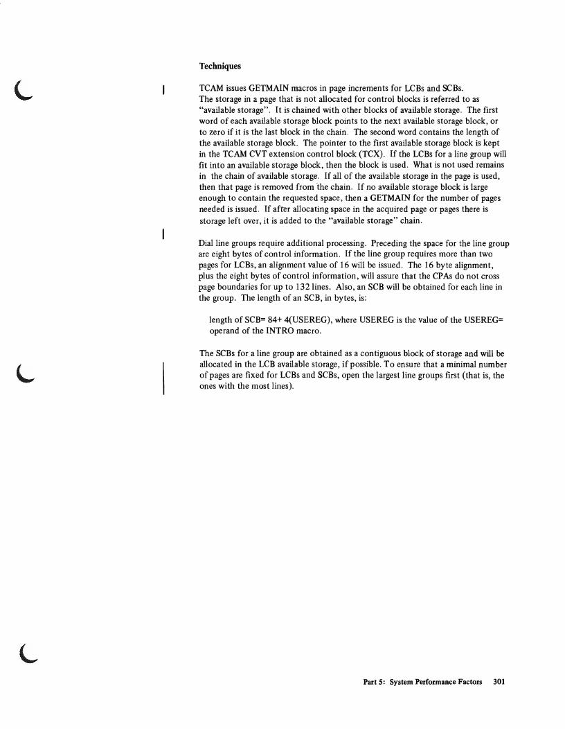
L Techniques
TCAM issues GETMAIN macros in page increments for LCBs and SCBs. The storage in a page that is not allocated for control blocks is referred to as "available storage". It is chained with other blocks of available storage. The first word of each available storage block points to the next available storage block, or to zero if it is the last block in the chain. The second word contains the length of the available storage block. The pointer to the first available storage block is kept in the TCAM CVT extension control block (TCX). If the LCBs for a line group will fit into an available storage block, then the block is used. What is not used remains in the chain of available storage. If all of the available storage in the page is used, then that page is removed from the chain. If no available storage block is large enough to contain the requested space, then a GETMAIN for the number of pages needed is issued. If after allocating space in the acquired page or pages there is storage left over, it is added to the "available storage" chain.
Dial line groups require additional processing. Preceding the space for the line group are eight bytes of control information. If the line group requires more than two pages for LCBs, an alignment value of 16 will be issued. The 16 byte alignment, plus the eight bytes of control information, will assure that the CPAs do not cross page boundaries for up to 132 lines. Also, an SCB will be obtained for each line in the group. The length of an SCB, in bytes, is:
length of SCB= 84+ 4(USEREG), where USEREG is the value of the USEREG= operand of the INTRO macro.
The SCBs for a line group are obtained as a contiguous block of storage and will be allocated in the LCB available storage, if possible. To ensure that a minimal number of pages are fixed for LCBs and SCBs, open the largest line groups first (that is, the ones with the most lines).
Part 5: System Performance Factors 301

TSO and Batch Service Trade-offs via the IPS
Preliminary studies with the default IPS indicate that several kinds of changes can result in a total net service gain overall. In all cases the gain is the result of improving batch service at some cost to TSO response times and, in particular, respons~ times for shorter TSO transactions. Changes are given and discussed below in their normal order of impact on service distribution (least to greatest).
• Changes to batch ISVs. Increasing batch ISVs can provide a slight increase in batch service but will decrease the workload manager's control of batch users.
• Changes to batch objectives. Improvements to batch objectives will mean some increase in batch service; however, unless caution is used, batch gains may result in heavy service losses and lengthly response times for second and third period TSO transactions.
• Changes to TSO first period objectives. You can obtain a significan t improvement in batch service, although at the expense of TSO response time, by either lowering the objective (for example, reducing the service rate from 100 to 20 at workload level 10) or by moving the zero service point to a lower workload level.
• Changes to TSO first period ISV. Increasing this ISV can mean, contrary to what might be expected, less service and longer response times for shorter TSO users. This is because the SRM uses the ISV in its TSO scheduling algorithm. As the ISV increases, it is assumed in effect that the TSO user tends to behave as a batch user. Thus, as the ISV increases, TSO users will tend to be scheduled and compete for service as if they were batch users. With large first period ISVs, TSO response time ceases to be a primary consideration and as a result can increase significantly. Batch users on the other hand benefit by being able to more actively compete for service and will generally receive substantial service gains. Particular caution should be used in increasing the first period TSO ISV above 160 service units since beyond that figure a uniform treatment is given to both batch and TSO transactions. Although batch service will greatly increase, TSO response time may also increase intolerably.
302 OS/VS2 System Programming Library: Initialization and Tuning Guide (VS2 Release 3.7)

L
L
Miscellaneous Performance Guidelines
The following tuning guidelines are reprinted from an Installation Newsletter.
• Data Set Placement: Locate the VTOC near the center of the pack, and place heavily used data sets close to the VTOC. Note that the relative importance (frequency of use) of system data sets has changed from that in OS/MVT. For example, SYSI.SVCLlB and SYS1.LlNKLlB had high frequency usage in OS/MVT. In MVS, the modules previously located on these data sets now reside in SYSI.LPALIB. The SYSRES data set placement used for benchmark measurement runs was:
Contents Cylinder
SYS 1.LP ALI B (1-36) SYS 1.P ARMLIB (37-46) SYS1.DUMPOO (47-52) SYS1.DUMPOI (53-56) SYS1.DSSVM (57-59) SYS1.NUCLEUS (66-80) SYS1.DCMLlB (81-82) SYS1.LOGON (136-137) SYS1.SVCLlB (138-142) SYS1.CMDLlB (143-152) SYS1.MACLlB (153-188) SYS 1.PROCLIB (189-194) SYS1.UADS (195-198) SYS1.BRODCAST (199-199) VTOC (200-200) CATALOG (201-225) SYS I.STGINDEX (226-231) SYS1.LlNKLlB (232-271) SYSl.MANX (272-281) SYS1.MANY (282-291) SYS1.HELP (388-388) SYS 1. TELCMLlB (391-398) SYS1.1MAGELlB (399-399) SYS1.LOGREC (400-401)
• Program Product Region Sizes: Specify a region size in the JCL for all Program Products which use GETMAIN to obtain all available storage. This will prevent the program from getting eight megabytes of virtual storage.
• Use of Initiators: Do not run in a highly overinitiated environment. Start at a conservative initiator level for example, and work up to the number of initiators that gives the balance of throughput and distribution of service that is desired.
Part 5: System Performance Factors 303

Miscellaneous Performance Guidelines (continued)
• loumaling: Measurements have shown up to 34% (a significant) increase in overhead because of journaling when running VIO and a workload containing many job steps.
304 OS!VS2 System Programming Library: Initialization and Tuning Guide (VS2 Release 3.7)

ABEND dump parameters as used with SYSABEND data set 48 as used with SYSUDUMP data set 58 need for care in changing them dynamically via the
CHNGDUMP command 48-49 absorption rate, definition of 163 address spaces
maximum number of concurrent address spaces 110 allocation, device, performance of (see Device Allocation
performance) AL TCPREC sysevent 280 APF (parameter in IEASYSxx) 92 APG (parameter in IEASYSxx) 93
precaution 93 routine in the System Resources Manager 169
appendages, EXCP 53 ASM (see Auxiliary Storage Manager) ASMCNSTS sysevent 277 authorized program facility (APF) parmlib member 52 automatic priority group (APG) parameter in IEASYSxx 93 Automatic Priority Group routine (in the SRM) 169 Auxiliary Storage Manager
algorithms and related guidelines 231 questions and answers 238
Auxiliary Storage Shortage Detection routine 168 (see also System Resources Manager constants 183, and
page space shortage 118) AVQLOW sysevent 275 AVQOK sysevent 276
BLDL or BLDLF (parameter in IEASYSxx) 94 BLDL list (IEABLDxx) 56
IBM-supplied default list 57 BUF (parameter in SMFPRMxx) 149 BUFFERS (TSO parameter) 133 BUFFERSPACE parameter, use of 257 BUFSIZE (TSO parameter) 133
catalog, VSAM performance factor guidelines 257 questions and answers 260
channel activity report (MF/l) description of 212 how to use it 225
CHNGDUMP command, precautions and example 48-49 CLPA (parameter in IEASYSxx), meaning and use 95 CMD (parameter in IEASYSxx; see also COMMNDxx) 97 COMMNDxx
detailed description 41 synopsis 27
concatenating libraries to LINKLIB 139 CONFIGCH sysevent 278 configuration, system, determining changes to 262 constants, SRM 183 CPU activity report
description of 210 how to use it 224
CPU (resource factor coefficient in IEAOPTxx) 181 CPU (service definition coefficient in IPS) 172-174 CPU Load Adjusting routine 167 crash, system, how to warm-start the system after 22 CSA (parameter in IEASYSxx) 98 CVIO (parameter in IEASYSxx) 99
Index
CVOL usage (see Using OS Catalog Management with the Master Catalog: CVOL Processor and VSAM Programmer's Guide)
DATASET sysgen macro rules and syntax example for specifying EXCP
appendages 53 used to specify page data sets 117 used to specify the PLPA 233
DEV ALLOC sysevent 278 device activity report (MF/l)
description of 215 how to use it 226
Device Allocation routine (in the SRM) 168 Device Allocation performance 252
guidelines for improving allocation response 253 how the SRM allocation algorithm supports I/O load
balancing 255 order in which requests are serviced 252 questions and answers 256
device class selection 208 device preference table, use of 253 device type (parameter in V ATLSTxx member) 157 DONTSWAP sysevent 285 DSV (parameter in SMFPRMxx) 149 DUMP (parameter in IEASYSxx) 100 dump
ABEND dump parameter IEAABDOO 48 IEADMPOO 58
SVC dump 100-102 DUR (sub parameter of PGN parameter in Installation
Performance Specification; see also performance group) 180 Dynamic Allocation, invoking from a batch job 254
ENQHOLD sysevent 274 ENQRLSE sysevent 274 Enqueue Delay Minimization routine (in the SRM) 170 enqueue residence value (ERV)
changing the 200 discussion of 182 syntax, value range, and example 77
ERV (see enqueue residence value) EXCP appendage, how to specify 53 EXT (parameter in SMFPRMxx) 150
FIX (parameter in IEASYSxx) 103 fixed link pack area list 61 FREE=CLOSE, use of 254
GMT (Greenwich mean time) 144 GTF
member of parmlib 43 parameters 45 starting GTF (general) 39 starting, via the IBM-supplied procedure 43, 45 used to trace sysevents 263
GTFPARM detailed description 43 synopsis 27
HARDCPY (parameter in IEASYSxx) 104 relationship with HARDCOPY parameter of SCHEDULR
macro at sysgen (see "Default Value" 105)
Index 305
INDEX

IEAABDOO (see also IEADMPOO) detailed description 47 synopsis 27
IEAAPFxx detailed description 52 synopsis 28
IEAAPPOO detailed description 53 synopsis 28
IEABLDxx default member, IBM-supplied 57 detailed description 56 synopsis 28
IEADMPOO (see also IEAABDOO) detailed description 58 synopsis 29
IEAFIXxx detailed description 61 synopsis 29
IEAIPSxx (see also System Resources Manager, how to use the; and IEAOPTxx)
detailed description 63 synopsis 30
IEALODOO (see also pageable link pack area) detailed description 72 synopsis 30
IEALPAxx (see also MLPA and link pack area, pageable) detailed description 73 synopsis 30
IEAOPTxx (see also System Resources Manager, how to use; and IEAIPSxx)
changing 201 discussion 181 syntax 75
IEAPAKBA (batch default pack list), description of 81 IEAPAKTS (TSO and batch default pack list), description of 80 IEAPAKOO (see also link pack area, pageable)
default lists, IBM-supplied 79 detailed description 78 ISAM pack list, suggested 241 synopsis 31
IEASYSxx (see also individual parameters) default contents 91 detailed description 85 incompatibilities with MVT and VS2 Release 1 parameters 88 MVT parameters, unsupported 88 overview of parameters 86 related sysgen macros 81 synopsis 32 syntax rules 91 VS2 Release 1 parameters, unsupported 90-91
IEASYSOO default contents 91 how overridden by IEASYSxx and operator 24 sysgen parameters copied to IEASYSOO 85
IEBUPDTE, example of statements 35 IKJPRMOO
detailed description 131 synopsis 32
INITATT sysevent 270 INITDET sysevent 270 initialization, system overview 20 initialization, use of parmlib 24 initiators, use of 303 INLOCKHI (TSO parameter) 133 INLOCKLO (TSO parameter) 133
installation performance specification (see also System Resource Manager)
member, IEAIPSxx 63 parameters 171 syntax, description of 63 how to change them 188
interval service .value (lSV) changing;the ISV 195 definition and example 180
I/O activity, comparison between problem program and the system 262
I/O device activity report (MF/l) description of 215 how to use it 226
I/O Load Adjusting routine 166 10C % coefficient)
resource factor coefficient in IEAOPTxx 181 service definition coefficient in IEAIPSxx 172-174
IPL, types of 22 IPS (see also installation performance specification)
changing the IPS between IPLs via SET IPS 38 default, description of 64 examples of 67,172-180 member description 63 parameter in IEASYSxx 106 syntax 63
ISV (subparameter of PGN parameter in Installation Performance Specification; see performance groups 180)
job wait limit (JWL parameter in SMFPRMxx) 147 JOBCAT DD statement, use of to speed catalog search 258 JOBS ELECT sysevent 269 JOBTERM sysevent 269 JWT (parameter in SMFPRMxx) 147
libraries that require authorization, how to specify 52 LlNKLlB
concatenating libraries with 139 link pack area
default pack lists 79 extension list (IEALPAxx) 73 fixed, use of 242 loading of 243-245 pack list (lEAP AKOO) 78 pageable: advantages, uses, recommendations 240
list capability for IPL and parmlib parameters description of operator responses needed to list IPL
parameters (see Operator's Library: OS/VS2 Reference (JES2) )
which parmlib members and IEASYSxx parameters can be listed 27
log (see LOGCLS and LOGLMT) LOGCLS (parameter in IEASYSxx) 108 logical groups handled by Auxiliary Storage Manager, limit on
the number of 11 0 LOGLMT (parameter in IEASYSxx) 109 LNK (parameter in IEASYSxx) 107 LNKLSTxx
detailed description 139 synopsis 33
load list (member IEALODOO) . detailed description 72 synopsis 30
306 OS/VS2 System Programming Library: Initialization and Tuning Guide (VS2 Release 3.7)

MAN (parameter in SMFPRMxx) 147 Mass Storage System
MVIKEYOO (in SYSl.PARMLIB) 141-143 PURGE parameter 120 Trace Report Programs 18
MAXUSER (parameter in IEASYSxx) 110 measurement facility (see MF/l) measurement tools
MF/l 203 SMF used to supplement MF/l 261 sysevent trace (GTF function) 263
MEMCREAT sysevent 268 MEMDEL sysevent 268 MF/l
how to use it (introduction) 203 messages 135-136 operator start command, example of 205 parameters
conflicts between 207 default 76-77 descriptions of (lRBMF1xx) 75 multiple sources of 205
procedure, IBM-supplied 204 reports and SMF records
channel activity 212, 225 CPU activity 210, 224 device activity 215,226 how to use the reports 224 paging activity 216,227 types of reports and SMF records 209 workload activity 220-228
MLPA (parameter in lEASYSxx) III modified link pack area list (lEALPAxx) 73 mount attribute (in VATLSTxx member)
definition 158 parameter position, meaning, and value range 157
mount message suppression (parameter in VATLSTxx member) 158
MSO (service definition coefficient in IPS) 172-174 MSS (see Mass Storage System) MVIKEYOO
detailed description 141-143 synopsis 33
NEWIPS sysevent 280 NIOWAIT sysevent 267 nucleus, map of (see NUCMAP) NUCMAP (parameter in lEASYSxx) 112
OBJ (subparameter of PGN in Installation Performance Specification; see performance group 180)
OKSWAP sysevent 184 OLTEP, real region size needed 121 operator commands (system) used to tailor the system 37 operator entry of parameters 23 operator intervention (see OPI, and operator entry of parameters) operator responses to SPECIFY SYSTEM PARAMETERS
message (see Operator's Library: OS/VS2 Reference (I£S2) OPI
parameter in IEASYSxx 113 parameter in SMFPRMxx 150
OPT paramp.ter in IEASYSxx 114 parameter in SMFPRMxx 146 tuning parameters for the SRM, discussion of 181
OWAITHI (TSO parameter) 133 OWAITLO (TSO parameter) 134
pack list (lEAP AKOO) default pack lists 79 description and use 78 ISAM pack list, suggested 241
PAGE (parameter in IEASYSxx) 115 Page Replacement (steal routine) 168 page stealing
definition of 168 routine 168
pageable link pack area (see also IEAPAKOO, IEALODOO, and IEALPAxx)
advantages, uses, and recommendations 240, 115 how PLPA is specified 115 ISAM pack list, recommended 241 loading of 243 module search sequence 243
paging activity report (MF 11 ) description of 216 how to use it 227
paging space, shortage of 118 paging data sets
guidelines for the use of 115,231 how to specify 115 minimum size requirements 118 questions and answers 238 reading from and writing to page data sets 236 requirements before IPL 117 space shortage 118
paging rates, comparison between problem program and system 261
parameters implicit 39-40 operator entry of 23 parmlib (see individual member names)
parmlib characteristics of each member, tabulated 27 how members are created 25 how to control it 35 member descriptions, detailed 41 relationships to IPL parameters and sysgen parameters 25 syntax rules, general 36
PARMTZ detailed description 144 synopsis 33
performance factors catalog 257 device allocation 252 miscellaneous 303 pageable link pack area 240 paging data sets 231 system 231 TCAM 294 TSO and Batch IPS Service 302 VIO 246
performance group period definition 164 discussion and examples 179
performance groups adding a new group 188 discussion and examples 179 modifying an existing group 190
performance objective changing an existing objective 191 definition of 162 discussion and examples 175
Index 307
PLPA (see also IEAPAKOO, IEALODOO, and IEALPAxx) advantages, uses, and guidelines 240 loading 243 module search sequence 243
PURGE (parameter in IEASYSxx) 120
QSCECMP sysevent 271 QSCEFL sysevent 273 QSCEST sysevent 271
REAL (parameter in IEASYSxx; see also VRREGN) 121 real storage
default region size for an ADDRSPC=REAL job 128 REC (parameter in SMFPRMxx) 149 reclaim rate, definition of 216 reconfigurable storage units 122 RECONLIM (TSO parameter) 134 reduction of data
SGP program to reduce SMF data 261 sysevent trace reduction
rationale 264-265 samples 289-293
reports, MF/1 (see also names of individual reports) descriptions of 209 how to use them 224
REQPGDAT sysevent 284 REQSERVC sysevent 283 REQSWAP sysevent 286 RESETPG sysevent 279 resource factor coefficeients (RFC)
meaning and use 181 syntax 95
resource factor coefficients (RFC) in IEAOPTxx changing 200 discussion 181 syntax 95
resource use routines (in the SRM) 166 response/throughput bias (RTB)
changing the RTB 195 discussion 181
RESVBUF (TSO parameter) 134 RFC (see resource factor coefficients) RSMCNSTS sysevent 275 RSTORCMP sysevent 273 RSU (parameter in IEASYSxx) 122 RTB (subparameter of PGN parameter in Installation
Performance Specification; see response/throughput bias)
saturation, system definition of 161 service, comparison between problem program and system 262 service, definition coefficients
changing the 198 defmition and example 172-174
service rate, definition and formula 160 SET IPS command, use of 38 SMF
as a measurement tool to supplement MF/l 261 data reduction program (SGP) 261 parameter in IEASYSOO 123 parameters in SMFPRMxx parmlib member 146
SMFPRMxx detailed description 146 overview 34
specific unit address, avoidance guideline 253 SQA
parameter in IEASYSxx 124 space shortage 124
SQALOW sysevent 276 SQAOK sysevent 277 ,
SRM (see System Resources Manager) SRM trace record, format and use 263 STEPCAT DD statement, use of to speed catalog search 258 SVC DUMP data set 100-102 SWINFL sysevent 272 SWOUTCMP sysevent 272 SYQSCCMP sysevent 282 SYQSCST sysevent 281 sysevents
meaning of the various sysevent codes 265-288 sample data reductions 289 tracing and data reduction 263
sysgen (see also individual macros) parameters that are copies to IEASYSOO 85 relationships between sysgen parameters and parmlib
members 25 SYSLOG (operand of HARDCPY parameter in IEASYSxx) 104 SYSP (parameter specified at IPL by the operator) 126 System Activity Measurement Facility (see also MF/1)
how to use it 203 parameters, description of 135
system initialization (see initialization) system parameter list (lEASYSxx)
detailed description 85 overview of parameters 86 synopsis 32
system performance factors 231 System Queue Area (SQA) Shortage Detection routine 168 System Resources Manager (SRM)
constants 182 control function 170 controlling the SRM 170 parameters, guidelines for defining 188
IPS parameters 172 OPT parameters 181
resource factor coefficients 181 resource use routines, descriptions of 166 service definition coefficients, definition of 172 Workload Manager functions 160 Workload Manager parameters 172
system workload level, definition of 161 SYSl.DUMPnn data set 100-102 SYS1.PARMLIB (see also names of individual members)
description of members 41 synopsis 27 use of (overview) 24
SYSl.STGINDEX, use of by the Auxiliary Storage Manager 116 SYSl.VTAMLST 38
TCAM changing parameters at START command 38 tuning considerations 294
Terminall/O Coordinator parameters (see TIOC parameters) TERMWAIT sysevent 266 TGETTPUT sysevent 281 thresholds, SRM 182 time sharing
how to start under MVS 38 maximum number of logged-on users (USERMAX
parameter) 134 parameters (IKJPRMOO) 131
time zone constant 144 TIMEREXP sysevent 266 TIOC parameters 131 TOD (keyword in COMMNDxx)
syntax and meaning 42 use of 144
TSEVENTOO sysevent 265
308 OS/VS2 System Programming Library: Initialization and Tuning Guide (VS2 Release 3.7)

L TSO
allocation suggestions 255 IPS service modifications 65 parameters 131
under-initiation, definition of 161 UNITNAME sysgen macro, use of
defining separate esoteric subgroups 253 specifying VIO data sets 249
UNT (sub parameter of PGN parameter in Installation Performance Specification; see also performance group period) 180
use attribute (in V ATLSTxx member) definition 152 position of parameter, meaning, and value range 156
USERMAX (TSO parameter) 134 USERRDY sysevent 267
VAL (parameter in IEASYSxx) 127 VATLSTxx
detailed description 152-153 synopsis 136 used for non-demountable devices 151
VERIFYPG sysevent 279 VIO
advantages 246 disadvantages 248 how to specify VIO data sets 249 performance considerations 248 questions and answers 250 window, definition and size 249
volume attribute list (VATLSTxx member) 151-153 (see also V A TLSTxx)
volume serial (parameter in VATLSTxx member) 157 VRREGN (parameter in IEASYSxx; see also REAL) 128 VSAM catalog
performance factor guidelines 257 questions and answers 260
VTAM default pack lists 79-80 SYSl.VTAMLST 37
V=R default region size 128
WKLDCOLL sysevent 287 WKLDINIT sysevent 287 WKLDTERM sysevent 288 working set, definition of 168 workload activity report (MF/I)
description of 220 how to use it 228
workload level numbers changing the 196 definition and example 174
workload level, system definition of 161
workload level, normalized definition of 162
Workload Manager, description of 160 WTL macro, maximum number allowed 109 WTO buffers, number of 128 WTOBFRS (parameter in IEASYSxx) 128 WTORPLY 130
Index 309

GC28-0681-2
~rn~ (J)
International Business Machines Corporation Data Processing Division 1133 Westchester Avenue, White Plains, New York 10604 (U.S.A. only)
IBM World Trade Corporation 821 United Nations Plaza, New York, New York 10017 (International)
< en N en "'0 r
::J ;::+' 0;'
N
'" .... 0' ::J
'" ::J
..) c.. -I c: ::J ::J
CC
G) c: c.: <"0
en W ....... 0 W ~
"'0 ~, ::J .... <"0 c.. ::J
C en ~
G) ("') N GO 0 a> CO .... N
0 ~
~ ." 0 c:
~ » 0' ::I
DQ
r :;' CD
OSIVS2 System Programming Library: Initialization and Tuning Guide
GC28-0681-2
Your views about this publication may help improve its usefulness; this form will be sent to the author's department for appropriate action. Using this form to request system assistance or additional publications will delay response, however. For more direct handling of such requests, please contact your IBM representative or the IBM Branch Office serving your locality.
Possible topics for comment are:
Clarity Accuracy Completeness Organization Index . Figures Examples Legibility
What is your occupation?
Number of latest Technical Newsletter (if any) concerning this publication:
Please indicate your address in the space below if you wish a reply.
Thank you for your cooperation. No postage stamp necessary if mailed in the U.S.A. (Elsewhere, an IBM office or representative will be happy to forward your comments.)
READER'S COMMENT FORM

GC28·0681·2
Your comments, please ...
This manual is part of a library that serves as a reference source for system analysts, programmers, and operators of IBM systems. Your comments on the other side of this form will be carefully reviewed by the persons responsible for writing and publishing this material. All comments and suggestions become the property of IBM.
o S. g ..., o Ii l> 0" :::J
IIQ
C :::J ..
I Fold Fold
- - -- --- - - - ---- - - --~-~
Business Reply Mail No postage stamp necessary if mailed in the U.S.A.
Postage will be paid by:
International Business Machines Corporation Department 058, Building 706·2 PO Box 390 Poughkeepsie, New York 12602
First Class Permit 81 Poughkeepsie New York
-----------------------~ Fold
lllID~ <l>
International Business Machines Corporation Data Processing Division 1133 Westchester Avenue, White Plains, New York 10604 (U.S.A. only)
IBM World Trade Corporation 821 United Nations Plaza, New York, New York 10017 (International)
Fold I I I I I I I I I I I I I I I I
< Ul "-> Ul "0 r
:I ;:j: iii· N til :. o :I til :I a. -i c: :I :I
(C
G) c: c: ~
"0 :::!. :I .... ~ a. :I
c en ;t>