vmebus extensions for instrumentation - vxibus extensions for instrumentation: fast data channel...
TRANSCRIPT

VMEbus Extensions for Instrumentation
Fast Data Channel SpecificationVXI-10
Revision 2.10July 17, 1995


NOTICE
The information contained in this document is subject to change withoutnotice.
The VXI Consortium, Inc. makes no warranty of any kind with regard to thismaterial, including, but not limited to, the implied warranties ofmerchantability and fitness for a particular purpose. The VXIbus Consortium,Inc. shall not be liable for errors contained herein or for incidental orconsequential damages in connections with the furnishing, performance, oruse of this material.
VMEbus Extensions for Instrumentation: Fast Data Channel Specification,VXI-10 Revision 2.10 is authored by the VXIbus Consortium, Inc. and itssponsor members.
This documnent is in the public domain. Permission is granted to reproduceand distribute this document by any means for any purpose.


CONTENTS
A. Introduction.....................................................................................................................................4A.1 Description ......................................................................................................................4A.2 Vocabulary ......................................................................................................................7A.3 FDC Memory Allocation Map..........................................................................................9
B. FDC Devices General Requirements ................................................................................................11B.2 Data Transfer Termination...............................................................................................13B.3 VXI Servant Requirements...............................................................................................15B.4 VXI Commander Requirements .......................................................................................16
C. Standard Word Serial Commands....................................................................................................17Channel Initialize........................................................................................17Channel Address Low, Channel Address High ............................................19Channel Size Low, Channel Size High........................................................20Go to Idle ....................................................................................................21Channel Close.............................................................................................23Transfer to Servant......................................................................................24Transfer to Commander ..............................................................................25FDC Event ..................................................................................................26FDC Supported ...........................................................................................27Passed Buffer ..............................................................................................28
C.2 Extended Word Serial Commands....................................................................................29Extended FDC Supported............................................................................30Extended Channel Initialize ........................................................................31Extended Channel Address .........................................................................33Extended Use Channel Address Low,Use Channel Address High ................34Extended Channel Size ...............................................................................35Extended Use Channel Size Low,Use Channel Size High ............................36Extended Go to Idle.....................................................................................37Extended Channel Close .............................................................................38Extended Transfer to Servant ......................................................................39Extended Transfer to Commander...............................................................40Extended FDC Event...................................................................................41Extended FDC Event Query ........................................................................42Extended Passed Buffer...............................................................................43
C.3 Examples .........................................................................................................................44C.3.1 FDC Channel Initialization Procedure.........................................................44C.3.2 Data transfer from Commander to Servant ..................................................45C.3.3 Data transfer from Servant to Commander ..................................................47C.3.4 Transfer Data using a Channel Pair.............................................................49C.3.5 Stream Data transfer from Commander to Servant ......................................50C.3.6 Abort Flag Usage ........................................................................................52C.3.7 Channel Termination Example....................................................................52

6
D. Message Transfer Protocol...............................................................................................................53D.1.1 Introduction ....................................................................................................53D.1.2 MTP Establishment and Termination ..............................................................53D.1.3 MTP Communication......................................................................................53D.1.4 MTP General Requirements ............................................................................54D.1.5 MTP Commanders ..........................................................................................54D.1.6 MTP Servants .................................................................................................55
E. MTP Commands..............................................................................................................................57MTP Supported...........................................................................................57MTP Initiate................................................................................................58MTP Terminate...........................................................................................59

A. Introduction
Fast Data Channel (FDC) protocol provides a mechanism for transferring data between a VXICommander and its Servants. The primary goals of FDC are:
Provide an efficient mechanism for transferring large blocks of data between VXI Commandersand their Servants.
Utilize standard, existing (VME compatible) hardware structures.
Minimize the complexity of the protocol, making software driver development easy and driverexecution fast.
The complexity of the software driver has been kept to a minimum to make implementation easy andexecution efficient. Memory which is accessible by both devices, a Message Based interface and a simplesoftware driver on the Commander and Servant are the only requirements for implementation of theprotocol.
A.1 Description
The FDC protocol supports the transfer of data blocks between a VXI Commander and its VXI Servant.The data can be moved from the Commander to the Servant or from the Servant to the Commander. Themedia used to move the data is electronic Memory which is accessible to both the Commander and theServant. VXI Word Serial commands are used to determine the size and location of the Memory. Simpleflags are used to handshake buffers of data between the Commander and the Servant, allowing thetransfer of data blocks larger than the available Memory.
The FDC protocol requires that a software driver exist on both the Commander and the servant. Thisdriver establishes the FDC Channel and manages data transfers. The VXI commander is responsible forFDC channel management and initiating any data transfers. The commander first sends the ChannelInitialize command to the servant. It then sends the Channel Address and Channel Size Word Serialcommands to determine the location and size of the FDC Area. At this point a valid FDC channel existsbetween the commander and the servant.
Once an FDC channel has been formed, it can be used to transfer data blocks between the VXIcommander and servant. To transfer data from the commander to the servant the FDC driver on thecommander sends a Transfer to Servant Word Serial Command. The servant responds by setting theappropriate flags in the Channel Header. Buffers of data are passed from the commander to the servantuntil the entire data block has been transferred.
To transfer data from the servant to the commander the Transfer to Commander Word Serial command issent to the servant. The servant responds by setting the appropriate flags in the Channel Header andbuffers of data are passed from the servant to the commander.
Four channel header flags are used to manage the transfer of data blocks. The WDY (Write Ready) andRDY (Read Ready) flags are used to pass buffers of data back and forth between the commander andservant. Either the commander or the servant owns the FDC area at any point in time. The owner of theFDC area has both read and write privileges to the channel header and buffer. The non-owner has onlyread privileges. The END flag informs the recipient of the data that this buffer of data is the last in thetransfer of the data block. While the transfer is in progress the channel is active. When no transfer is inprogress the channel is idle.

8
A fourth bit in the FDC Header is the ABT (Abort) bit. If either the commander or servant chooses toprematurely terminate the transfer, it can set the abort bit when it receives ownership of the FDC Area.The device setting the error bit is the abort generator. Once the abort generator sets the error bit, it passesthe FDC area to the abort receiver. The abort receiver acknowledges the abort by clearing the abort bitand terminating the transfer. When the abort generator detects the acknowledgment it also terminates thetransfer. This places the FDC channel into the idle state. The data block being transferred is invalid if thetransmission is terminated by the abort bit. Reporting of the abort to the user application is an instrumentspecific function.
Two classes of FDC channels are defined: Standard and Extended. Standard channels are managed with16 bit Word Serial Commands and are limited to 8 total channels. Extended channels are managed with32 bit long Word Serial commands providing up to 216 channels. Extended channels may also utilizememory which is external to the VXI servant. All channels are formed between a commander and itsdirect servant. Each of these channels are independent: They each have unique FDC areas.
Enhanced throughput may be achieved by utilizing a pair of FDC channels in tandem. Pairs are formedusing adjacent even-odd channels i.e. 0-1, 2-3, 4-5, .... The lower numbered channel always transfers thefirst buffer of data in a block of data. The sender switches back and forth between the channels as it sendsthe data block. The receiver tracks this action, switching back and forth between the two channels as itreads each buffer of data. Using FDC channel pairs allows the sender to write a buffer of data to onechannel while the receiver is reading a buffer of data from the other channel.
An FDC channel can be one of two types: Normal or Stream. A Normal channel transfers blocks of dataand transitions between the idle and active states. Each transfer is initiated by Transfer to Commander orTransfer to Servant command. When the last buffer of data is transferred the channel will transition to theidle state.
A Stream channel is always in the active state. It is established in the same manner as a normal channelexcept the ST flag is set in the Transfer to Servant/Commander command. A Transfer to Servant orTransfer to Commander command is sent only once, when the channel is formed to establish the directionof the stream. Buffers of data are passed in the regular fashion. The END bit is used to separate datablocks but does not terminate the transfer. The ABT bit indicates that the most recent data blocktransferred was invalid and should be discarded for instrument specific reasons. The abort detector mustacknowledge the abort and clear the ABT bit before passing the FDC area back to the abort generator.Stream channels are terminated by sending the Go to Idle command.
Message Transfer Protocol (MTP) provides a mechanism for sending control messages to the VXI moduleand retrieving response messages from the VXI module. This protocol is designed to provide analternative mechanism to the VXI Word Serial Byte Transfer protocol (BTP) . Message Transfer Protocolutilizes the capabilities the FDC protocol to send control messages to message based VXI modules andretrieve their response messages.
Three modes of access to the FDC buffer are supported to allow efficient implementation of instrumenthardware: random, linear, and FIFO access. Random allows data access in any sequence any number oftimes. Linear requires a single sequential data access through the buffer. FIFO places the entire databuffer behind a single address and requires repeated access of that single location. Supported FDC dataaccess modes are indicated by the response from the Channel Initialize command.
The format of the data transferred via FDC Normal and Stream channels is not defined by the FDCprotocol. It is the responsibility of the module manufacturer and the user to ensure the data transferred isusable by the VXI commander or servant devices. Where appropriate, it is recommended that data

9
identification information be included in the data block so that error checking can be made. If invalid datais sent to the servant or commander the Abort bit can be set and the transfer aborted.

10
A.2 Vocabulary
FDC: Fast Data Channel - A VXI protocol which supports the transfer of data between Commanders andServants.
FDC Area: A portion of memory which is accessible to both the VXI commander and servant which isallocated to the FDC Channel. This memory contains the Channel Header and Channel data Buffer.
Channel Header: The first 8 bytes of the FDC area. The header contains the FDC Version, data buffermanagement flags and the data size value.
Channel Buffer: The portion of the FDC area directly following the channel header and extending to theend of the FDC area. The data buffer is used to temporarily store data being transferred.
Channel: The memory and protocol which provides the data transport mechanism for FDC.
Data Block: A well defined array of packed binary data of a specific size.
Buffer of Data: A buffer of data is a logical construct which contains two elements. The first element isall or a portion of the data in a data block to be transferred using FDC protocol. The second element is a32 bit unsigned integer which reflects the number of bytes contained in this particular portion of the datablock.
Idle Channel: An FDC channel which has been initialized but is not currently engaged in transferringdata.
Active Channel: An FDC channel which is currently engaged in transferring data.
Abort Generator: An FDC device which, during this transfer, has set the ABT (Abort) bit.
Abort Receiver: An FDC device which, during this transfer, will acknowledge the ABT bit which wasset by the other FDC device.
FDC area ownership: One of the two FDC devices which have formed a valid FDC channel hasownership of the FDC area. If the Read Ready (RDY) and Write Ready (WDY) bits are 0 the Servantowns the FDC area. Otherwise, the Commander owns the FDC area. The owner of the FDC area has readand write privileges to the FDC area. The non-owner may read the FDC area but must not write to theFDC area.
FDC Driver: A software or firmware algorithm which implements the FDC protocol.
Normal Channel Transfer: An FDC channel which can be used to transfer discrete data blocks. Anormal channel transitions between the active and idle state for each data block transfer.
Stream Channel Transfer: An FDC channel which is always active and is able to pass a continuous flowof data.
Standard Channel: An FDC channel which uses the 16 bit standard FDC commands for channelmanagement.

11
Extended Channel: An FDC channel which uses the 32 bit extended FDC commands for channelmanagement.
Alternate Command Set: A set of 16 bit Word Serial Command Codes which are provided for backwardscompatability to prior versions of the FDC standard.

12
A.3 FDC Memory Allocation Map
The FDC area contains the FDC Channel header information and the FDC data buffer.
BIT 7 - 4 3 2 1 0
FDC Channel HeaderBYTE 0 MINOR REV. MAJOR REVISIONBYTE 1 RSVD RSVD RSVD RSVD RSVDBYTE 2 RSVD RSVD RSVD RSVD TRIGBYTE 3 RSVD ABT RDY WDY ENDBYTE 4 DATA SIZE BITS 31-24BYTE 5 DATA SIZE BITS 23-16BYTE 6 DATA SIZE BITS 15-8BYTE 7 DATA SIZE BITS 7-0
FDC Channel BufferBYTE 8 DATA BUFFER BYTE 0 (FIFO BITS 31-24)BYTE 9 DATA BUFFER BYTE 1 (FIFO BITS 23-16)BYTE 10 DATA BUFFER BYTE 1 (FIFO BITS 15-8)BYTE 11 DATA BUFFER BYTE 1 (FIFO BITS 7-0) . . .BYTE N DATA BUFFER BYTE N-8
Notes
RSVD : These bits are reserved and should be set to 0.
MAJOR REVISION: Version of FDC protocol. Must be 216.
MINOR REVISION: Version of FDC protocol. Must be 116.
TRIG: The TRIG bit is utlilized only within Message Transfer Protocol (MTP) to send the MTP Triggrercommand. It has no meaning outside of MTP and should be set to 0. In MTP the TRIG bit is set to 1 bythe commander and the FDC area passed from the commander to the servent to deliver the MTP Triggercommand (equivalent to the VXI Word Serial Trigger command).
END: The END bit indicates whether this buffer of data is the last buffer of data in a normal channel. Ifthe END bit is set to 1, this is the last buffer of data to transfer. If the END bit is set to 0 , this is not thelast buffer of data.
In a stream channel the end bit is used to separate data blocks but does not indicate termination of thetransfer. The data sender sets the END bit on the last buffer of data in this data block. The data receiversets the END bit back to 0 when it receives the buffer.
In Message Transfer protocol, the END bit is associated with the last byte of data within the buffer of data.
WDY: The WDY flag is utilized when data is transferred from the Commander to the Servant. If theWDY bit is set to 1, the Commander owns the FDC area. It can place a buffer of data into the FDC area

13
and then set WDY to 0 to pass the buffer of data to the Servant. If the WDY bit is set to 0, the VXIServant owns the FDC area. It will read the buffer of data and then set WDY high to pass the FDC areaback to the Commander. When the channel is in the idle state, WDY is 0.
RDY: The RDY flag is utilized when data is transferred from the Servant to the Commander. If the RDYbit is set to 0, the VXI Servant owns the FDC area. It can place a buffer of data into the FDC area and setthe RDY bit to 1 to pass the buffer of data to the Commander. If the RDY bit is set to 1, the Commanderowns the FDC area. The Commander can read the buffer of data and then set the RDY bit to 0 to pass theFDC area back to the Servant. When the channel is in the idle state, RDY is 0.
ABT: The ABT bit indicates that an abort trasfer is being requested on an active channel. The owner ofthe FDC area (abort generator) may set the ABT bit to a 1 to request that a data transfer in progress beaborted. The abort generator then passes ownership of the FDC area to the abort receiver.
In a Normal channel the abort receiver sets the ABT, RDY, WDY and END bits to 0 (zero) and returnsthe channel to the Idle state. It discards any data which was received during the aborted transfer. Theabort generator returns the channel to the Idle state when the ABT bit is returned to 0 by the abortreceiver.
In a Stream channel the abort receiver sets the ABT bit to 0 but does not change the state of the channel;the channel remains in the Active state. It discards any data which was received during the aborted blocktransfer.
When the abort receiver is the servant and the channel was established with a Transfer To Servantcommand, the error receiver must pass the FDC area to the commander. If the abort receiver is thecommander and the channel was established with a Transfer To Commander command, the error receivermust pass the FDC area to the servant. If the stream channel utilizes a channel pair then both FDC areasshould be returned as defined above.
DATA SIZE: The FDC DATA SIZE contains the number of bytes contained in this buffer of data.
DATA BUFFER: Memory area where the data to be transferred is placed. There are 3 modes of accesssupported for the data buffer: random, linear, and FIFO. Random access allows the buffer to be accessedin any order any number of times. Linear requires the buffer to be accessed from start to end incrementingto the next address on each access. Each location may be accessed only once. FIFO mode requires that theFDC Buffer is read repeatedly at the defined offset for the specified data size. It must be read the numberof times indicated by the DATA SIZE value (not the number of bytes). Valid data access modes and sizesare indicated when the channel is intialized.


B. FDC Devices General Requirements
RULE B.1.1 :An FDC device SHALL be a message based device.
RULE B.1.2 :A device SHALL indicate its support for FDC protocol by correctly responding to the FDC SupportedWord Serial Command. The standard Word Serial command SHALL be tested first. If the standardcommand fails then the alternate command value SHALL be tested. The success of one of thesecommands SHALL set the command type for all following commands.
RULE B.1.3 :An FDC channel SHALL NOT be shared by more than two VXI devices.
RULE B.1.4 :An FDC channel SHALL NOT be established other than between a VXI Servant and its VXIcommander.
RULE B.1.5 :When FDC channels are used in pairs then the pairs SHALL be formed between adjacent channels usingthe algorithm 2*N and (2*N) + 1 where N = 0, 1, 2, ... e.g.: 0 and 1, 2 and 3, 4 and 5 etc.
RULE B.1.6 :When FDC channels are used in pairs then the first buffer of data SHALL be sent on the lower numberedpair. The second buffer of data SHALL be sent on the higher numbered pair. Data buffer transmissionSHALL continue to switch back and forth between the pair until the entire block of data is transferred orthe transfer is terminated by an error.
RULE B.1.7 :If a stream channel error receiver is the servant in a transfer to servant channel, it SHALL discard datatrasferred in the current block and return the FDC area to the commander. If the stream utilizes a channelpair then both FDC areas SHALL be returned to the commander.
RULE B.1.8 :If a stream channel error receiver is the commander in a Transfer To Commander channel, it SHALLdiscard data trasferred in the current block and return the FDC area to the Servant. If the stream utilizes achannel pair then both FDC areas SHALL be returned to the servant.
RULE B.1.9 :An FDC channel SHALL be established in an area of memory accessible to both FDC devices.
RULE B.1.10 :The FDC area base address SHALL be aligned on a double long word (8 bytes) boundary.

16
RULE B.1.11 :An FDC device SHALL NOT write to the FDC area unless it has ownership of the FDC area.
OBSERVATION B.1.12 :If the WDY and RDY bits are both 0 then the servant owns the FDC area. If either of the WDY or RDYbits is 1 then the commander owns the FDC area
RULE B.1.13 :
When a device receives ownership of the FDC area during an FDC transfer, it SHALL first check theABT bit. If the ABT bit is set, the device SHALL acknowledge the abort and if it is a normal channel,return to the idle state.

17
B.2 Data Transfer Termination
Normal channel transfer termination is archived by setting the END bit in the channel header. When theEND bit is set, it indicates that this is the last buffer of data to transfer. The transfer may also beterminated by setting the ABT bit. However, terminating a transfer with the ABT bit invalidates the dataalready transferred.
Setting the END bit in a Stream channel defines the end of a data block but does not terminate the datatransfer. Stream channels are always active. To terminate a stream the Go to Idle command must be sent.
RULE B.2.1 :For Normal channels, an FDC commander during a Transfer To Servant or a FDC servant during aTransfer To Commander (the data source) SHALL set the END bit on the transfer of the last buffer ofdata, even if the transfer of data involves only one buffer of data. The transfer is not complete until theFDC servant during a Transfer to servant or commander during a transfer to commander (the datadestination) clears the END bit to 0. If the FDC area is passed back from the data destination device to thedata source device with the ABT bit set, the abort generator/receiver sequence SHALL be executed.
RULE B.2.2 :For Stream Channels, an FDC commander during a Transfer To Servant or a FDC servant during aTransfer To Commander (the data source) SHALL set the END bit on the transfer of the last buffer ofdata within the current data block, even if the transfer of data involves only one buffer of data. Thetransfer is not complete until the FDC servant during a Transfer to servant or commander during atransfer to commander (the data destination) clears the END bit to 0 and returns ownership of the FDCarea to the data source device. If the FDC area is passed back to the data source device with the ABT bitset to 1, the stream abort generator/receiver abort sequence SHALL be executed.
OBSERVATION B.2.1 :In a stream channel each block of data will be transferred as one or more buffers of data. Because theboundaries between the blocks are identified by the end bit which is associated with the last byte in thecurrent buffer of data, any buffer of data may contain information from a single block: a buffer of data willnever contain components from the end of one block and the beginning of the next block.
RULE B.2.3 :For Normal channels, an FDC servant during a Transfer To Servant or a FDC commander during aTransfer To Commander (the data destination) SHALL clear the END bit to 0 on the successful receipt ofthe last buffer of data. If the receipt of the last buffer of data is not successful, it SHALL NOT clear theEND bit to 0. It SHALL set the ABT bit to 1 and pass the FDC area back to the FDC commander duringa Transfer To Servant or a FDC servant during a Transfer To Commander (the data source) to indicate atransfer abort. If the FDC area is passed back from the data destination device to the data source devicewith the ABT bit set, the Normal generator/receiver abort sequence SHALL be executed.
RULE B.2.4 :For Stream channels, an FDC servant during a Transfer To Servant or a FDC commander during aTransfer To Commander (the data destination) SHALL clear the END bit to 0 on the successful receipt ofthe last buffer of data and pass the FDC area to the FDC commander during a Transfer To Servant or aFDC servant during a Transfer To Commander (the data source). If the receipt of the last buffer of data isnot successful, it SHALL NOT clear the END bit to 0. It SHALL set the ABT bit to 1 and pass the FDC

18
area back to the data source device to indicate a transfer abort. If the FDC area is passed back from thedata destination device to the data source device with the ABT bit set, the stream generator/receiver abortsequence SHALL be executed.
RULE B.2.5 :When a Normal channel pair receives a buffer of data with the END flag set, it SHALL acknowledge thecompletion of the transfer and then return both channels of the pair to the idle state.
RULE B.2.6 :When a Normal channel pair receives a buffer of data with the ABT flag set, it SHALL acknowledge theabort and then return both channels of the pair to the idle state.
RULE B.2.7 :When a Normal channel pair sends an ABT or a END and receives acknowledgement, it SHALL thenreturn both channels of the pair to the idle state.
OBSERVATION B.2.2 :During a normal FDC transfer, ownership of the flags and data buffers is passed back and forth betweenthe sender and the receiver. The ABT flag can only be set by the current owner of the FDC area. Once theABT flag has been set, ownership must be passed to the other side for acknowledgment.
OBSERVATION B.2.3 :Setting all flag bits to 0 during a normal FDC error acknowledgment places them in the initializationstate. This readies the channel for the next FDC transfer.

19
B.3 VXI Servant Requirements
RULE B.3.1 :A VXI servant SHALL NOT initiate FDC channel establishment or data transfer.
PERMISSION B.3.1 :A VXI FDC servant device MAY support only the capability to send data or to receive data on aparticular channel. The servent is not required to do both.
PERMISSION B.3.2 :The VXI commander MAY initiate the FDC channel establishment or a data block transfer as the resultof a request received from its servant.
RULE B.3.2 :A VXI servant which implements the FDC protocol version 2.1 or greater SHALL implement allStandard FDC Word Serial Protocol Commands.
RULE B.3.3 :A VXI servant which implements the FDC Extended Long Word Serial Commands SHALL implementall defined extended commands.
OBSERVATION B.3.1 :A VXI servant must implement all commands. However, this does not require that the servant be capableof sending or recieveing data. The Transfer To Servant or Transfer To Commander command may returna not supported response.
RULE B.3.4 :The VXI servant MAY implement the required Word Serial Commands using standard Word Serialcommand codes or alternate command codes.
RULE B.3.5 :When the FDC channel is active and the servant has ownership of the FDC area, the VXI servant SHALLtest the ABT flag and take appropriate actions prior to passing FDC area ownership to the commander.
RULE B.3.6 :If a servant supports the Passed Buffer command, it SHALL return a 0 (zero) in bit position 3 of theresonse word of all Channel Initialize commands sent to the servant. Otherwise it SHALL return a 1.

20
B.4 VXI Commander Requirements
Two sets of command codes are defined by the FDC specification: standard and alternate command codes.Standard command codes are 16 bit Word Serial Commands which are defined within the VXI reservedarea. Alternate command codes are defined in the user defined Word Serial command area. Bit position15 is a 1 for the standard commands and a 0 for the alternate commands. All other bit positions areidentical.
Alternate command codes are provided for backwards compatability with previos versions of the FDCstandard. New implementations of FDC servants should use only the standard command codes. Thestandard FDC event has bit 14 set 1 and the alternate event has bit 14 set to 0.
RULE B.4.1 :Commanders which provide FDC services to the user SHALL support both the standard and alternatecommand codes and events.
RULE B.4.2 :When the FDC channel is active and the commander receives ownership of the FDC area, the VXIcommander SHALL test the ABT flag prior to passing FDC area ownership to the servant. If the ABT bitis set, the commander should follow the specified abort acknowledge sequence for the current mode of thechannel.
RULE B.4.3 :If the servant indicates support for the Passed Buffer command, the commander SHALL send the PassedBuffer command to the servant each time it passes a buffer to the servant. The Passed command is sentafter the buffer has been passed via the FDC header flags.


C. Standard Word Serial Commands
Channel InitializeThis command is used to validate and initialize the FDC area.
The syntax of the Channel Initialize command is defined in the following table.
Bit #15 14 13 12 11 10 9 8 7 6 5 4 3 2 1 0AC 0 0 1 1 1 1 1 1 0 0 1 0 Channel #
Channel # : number 0 - 7 selecting a particular channelAC : Standard code = 1, Alternate code = 0
A single response word is placed in the Data Low register in the following format:
Bit #15 14 13 12 11 10 9 8 7 6 5 4 3 2 1 0
Status 1 ADDR DATA PC MODE
Status: This field indicates status of the Channel Initialize command.
F16 - The Buffer Initialize command executed with no errors. 716 - ERROR - Channel already open. 616 - ERROR - No valid FDC area can be allocated. 516 - ERROR - This FDC channel number not supported.
ADDR : Supported address space1 - A16 space2 - A24 space4 - A32 space
DATA : Allowed Data Sizes1 - D082 - D164 - D328 - D64
PC : Pass Command Supported0 - Supported1 - Not Supported

23
MODE : Data Buffer mode1 - Random access2 - Linear access4 - FIFO access
The following restrictions apply to the above flags:
1. The ADDR field may only contain the listed values.2. For MODE = 1 (random) the DATA field value may be any bit-wise combination of the listed values.3. When MODE = 2 or 4 the DATA field may contain only the listed values. Only one data width is
allowed. All accesses to the FDC data buffer for these modes must be of the indicated size. The FDCheader is restricted to D16 accesses.
The Channel Initialize command must initialize the FDC header area for the selected channel beforereturning a success response. The header RSVD, flag bits, and data size should be set to zero. The versionnumber should be set appropriately. It should place the channel in the idle state.

24
Channel Address Low, Channel Address High
These commands are used to retrieve the FDC area base address from the servant. The FDC address andsize defines a memory area within the address space returned by the Channel Initialize command.
The syntax of the Channel Address Low command is defined in the following table.
Bit #15 14 13 12 11 10 9 8 7 6 5 4 3 2 1 0AC 0 0 1 1 1 1 1 0 0 0 0 0 Channel #
The syntax of the Channel Address High command is defined in the following table.
Bit #15 14 13 12 11 10 9 8 7 6 5 4 3 2 1 0AC 0 0 1 1 1 1 1 1 0 0 0 0 Channel #
Channel # : number 0 - 7 selecting a particular channelAC : Standard code = 1, Alternate code = 0
A single response data word is placed in the Data Low register for each command in the following format:
Response Word
Bit #15 14 13 12 11 10 9 8 7 6 5 4 3 2 1 0
FDC Area Address Low or High Word
If no valid FDC area can be allocated, the value returned in the low and high response words should be$HFFFF.

25
Channel Size Low, Channel Size High
These commands are used to retrieve the FDC area size. The FDC size identifies the memory areaallocated to this FDC channel starting at the Address returned by the Channel Address Low and Hicommands.
The syntax of Channel Size Low command is defined in the following table.
Bit #15 14 13 12 11 10 9 8 7 6 5 4 3 2 1 0AC 0 0 1 1 1 1 1 0 0 0 0 1 Channel #
The syntax of Channel Size High command is defined in the following table.
Bit #15 14 13 12 11 10 9 8 7 6 5 4 3 2 1 0AC 0 0 1 1 1 1 1 1 0 0 0 1 Channel #
Channel # : number 0 - 7 selecting a particular channelAC : Standard code = 1, Alternate code = 0
A single response word is placed in the Data Low register for each command in the following format:
Response Word
Bit #15 14 13 12 11 10 9 8 7 6 5 4 3 2 1 0
FDC Area Size Low or High Word
If no valid FDC area can be allocated, the value returned in the first and second response words should be000016.
The channel size is defines the total memory allocated to the FDC protocol for this channel. It is the sumof the FDC Channel Header and Channel buffer.

26
Go to IdleThis command is used to terminate a Stream transfer. It may also be used to force termination of a Normaltransfer.
The syntax of the Go to Idle command is defined in the following table.
Bit #15 14 13 12 11 10 9 8 7 6 5 4 3 2 1 0AC 0 0 1 1 1 1 1 1 0 1 1 IM Channel #
Channel # : number 0 - 7 selecting a particular channelIM : Immediate Flag0 - Transition to idle state at the end of the current block transfer1 - Transition to idle immediately and re-initialize the buffer headerAC : Standard code = 1, Alternate code = 0
A single response word is placed in the Data Low register in the following format:
Bit #15 14 13 12 11 10 9 8 7 6 5 4 3 2 1 0
Status 1 1 1 1 1 1 1 1 1 1 1 1
Status: This flag indicates status of the Go to Idle command.
F16 - The channel has returned to the idle state. 716 - PENDING - The channel is still active and will be returned to
idle at the end of the current block of data. 616 - ERROR - Can't idle a closed channel. 516 - ERROR - This FDC channel number not supported. 416 - ERROR - Command not allowed.
The Go to Idle command is used to terminate a stream transfer. If the immediate flag is zero, the currentdata block transfer should be completed before terminating the stream and returning the channel to theidle state.
For a channel established as transfer to servant, the current block transfer is comlete when the servant hassuccessfully accepted a buffer of data with the end bit set and no longer has ownership of the FDC area.For a channel established as transfer to commander, the current block transfer is comlete when the servanthas successfully transferred a buffer of data with the end bit set to the commander and the servant hasownership of the FDC area.
If the PENDING response is returned, the servant will transition to the idle state at the completion of thecurrent block transfer. To determine that the transfer is complete, the commander may send the Go to Idlecommand as many times as necessary, evaluating the response.
If the immediate flag is set to one, the servant must clear all of the header flags to zero and return thechannel to the idle state before returning its response. Once Go to Idle Immediate is sent, the controllermust not access the channels FDC area until it requests another transfer.
Sending Go to Idle to a normal and active channel has no affect and returns the PENDING response.However, sending Go to Idle Immediate will cause the normal channel to terminate in the same manner asa stream channel. This may be done to abort a transfer in progress and will result in loss of data.

27
Sending the Go to Idle command to one member of a channel pair causes both channels to transition tothe idle state.

28
Channel CloseThis command is used to close the FDC channel.
The syntax of the Channel Close command is defined in the following table.
Bit #15 14 13 12 11 10 9 8 7 6 5 4 3 2 1 0AC 0 0 1 1 1 1 1 1 0 0 1 1 Channel #
Channel # : number 0 - 7 selecting a particular channelAC : Standard code = 1, Alternate code = 0
A single response word is placed in the Data Low register in the following format:
Bit #15 14 13 12 11 10 9 8 7 6 5 4 3 2 1 0
Status 1 1 1 1 1 1 1 1 1 1 1 1
Status: This flag indicates status of the Channel Close command. F16 - The Channel Close command executed with no errors. 716 - ERROR - Attempt to close a channel that is not open. 616 - ERROR - Attempt to close a channel that is active.

29
Transfer to ServantThis command is used to initiate a data block transfer from the commander to the servant.
The syntax of the Transfer to Servant command is defined in the following table.
Bit #15 14 13 12 11 10 9 8 7 6 5 4 3 2 1 0AC 0 0 1 1 1 1 1 1 1 0 PR ST Channel #
Channel # : number 0 - 7 selecting a particular channelST : Stream Flag
0 - Transfer is a Normal data block transfer1 - Transfer is a Stream transfer
PR : Channel Pair Flag0 - Channel is not to be used as a pair1 - Channel is to be used as a pair.
AC : Standard code = 1, Alternate code = 0
Note: The PR bit may be set only for channels 0,2,4, and 6. If this bit is set, the corresponding channelpair is made active.
A single response word is placed in the Data Low register in the following format:
Bit #15 14 13 12 11 10 9 8 7 6 5 4 3 2 1 0
Status 1 1 1 1 1 1 1 1 1 1 1 1
Status: This flag indicates status of the Transfer to Commander command. F16 - No errors detected. Data transfer will commence. 716 - ERROR - Request to send data with no valid FDC channel. 616 - ERROR - Request to send data when FDC channel is already active. 516 - ERROR - PR bit not legal for this channel. 416 - ERROR - Unable to utilize channel pair. 316 - ERROR - Unable to receive data for instrument specific reasons. 216 - ERROR - Unsupported mode (stream, normal or direction)
The Transfer to Servant command should clear the ERR, RDY, and END bits to zero, and WDY to onebefore returning the response. It should transition the channel state to active.

30
Transfer to CommanderThis command is used to initiate a data block transfer from the servant to the commander.
The syntax of the Transfer to Commander command is defined in the following table.
Bit #15 14 13 12 11 10 9 8 7 6 5 4 3 2 1 0AC 0 0 1 1 1 1 1 1 1 1 PR ST Channel #
Channel # : number 0 - 7 selecting a particular channelST : Stream Flag
0 - Transfer is a normal data block transfer1 - Transfer is a Stream transfer
PR : Channel Pair Flag0 - Channel is not to be used as a pair1 - Channel is to be used as a pair.
AC : Standard code = 1, Alternate code = 0
Note: The PR bit may be set only for channels 0,2,4, and 6. If this bit is set, the corresponding channelpair is made active.
A single response word is placed in the Data Low register in the following format:
Bit #15 14 13 12 11 10 9 8 7 6 5 4 3 2 1 0
Status 1 1 1 1 1 1 1 1 1 1 1 1
Status: This flag indicates status of the Transfer to Commander command. F16 - No errors detected. Data transfer will commence. 716 - ERROR - Request to send data with no valid FDC channel. 616 - ERROR - Request to send data when FDC channel is already active. 516 - ERROR - PR bit not legal for this channel. 416 - ERROR - Unable to utilize channel pair. 316 - ERROR - Unable to send data for instrument specific reasons. 216 - ERROR - Unsupported mode (stream, normal or direction)
The Transfer to Commander command should clear the ERR, RDY, WDY, and END bits to zero beforereturning the response. It should transition the channel state to active.

31
FDC EventThis command is used to control FDC event generation.
The syntax of the FDC Event command is defined in the following table.
Bit #15 14 13 12 11 10 9 8 7 6 5 4 3 2 1 0AC 0 0 1 1 1 1 1 1 0 1 0 EV Channel #
Channel # : number 0 - 7 selecting a particular channel
EV: Event Enable Bit
0 - No events are generated by FDC protocol1 - The Servant will send an event when it passes the FDC area to the Commander.AC : Standard code = 1, Alternate code = 0
A single response word is placed in the Data Low register in the following format:
Bit #15 14 13 12 11 10 9 8 7 6 5 4 3 2 1 0
Status 1 1 1 1 1 1 1 1 1 1 1 1
Status: This flag indicates status of the Event command. F16 - No errors detected. 716 - ERROR - Events not supported.
Events return a 16 bit value to the commander which uniquely identifies the event. The format of thereturn value for FDC events is described below.
15 14 13 12 11 10 9 8 7 6 5 4 3 2 1 01 AC 0 0 1 Channel # Servants Logical Address
Channel#: The channel selected by the commandServants Logical Address: The logical address of this moduleAC : Standard code = 1, Alternate code = 0
When the FDC Event is enabled for a particular FDC channel, the Event will be sent to the commandereach time FDC buffer ownership is passed back to the commander.
To ensure correct operation of Events, an event/interrupt handler must be installed on the commander.Failure to install the handler may cause poor performance or communication failure.

32
FDC SupportedThis command is used to determine FDC support.
The syntax of the FDC Supported command is defined in the following table.
Bit #15 14 13 12 11 10 9 8 7 6 5 4 3 2 1 0AC 0 0 1 1 1 1 1 0 0 0 1 1 1 1 1
AC : Standard code = 1, Alternate code = 0
A single response word is placed in the Data Low register in the following format:
15 14 13 12 11 10 9 8 7 6 5 4 3 2 1 0C7 C6 C5 C4 C3 C2 C1 C0 Revision
Revision: FDC revision level as defined in section AC0..C7: Available channels
1 = available0 = not available

33
Passed BufferThis command informs the servant that the commander has passed the buffer to the servant.
The syntax of the Passed Buffer command is defined in the following table.
Bit #15 14 13 12 11 10 9 8 7 6 5 4 3 2 1 0AC 0 0 1 1 1 1 1 0 0 0 1 0 Channel #
Channel # : number 0 - 7 selecting a particular channelAC : Standard code = 1, Alternate code = 0
The Passed Buffer command eliminates the requirement for the FDC servant to continuously poll the FDCheader bits to determine when the commander passes the FDC buffer. If the servant utilizes thiscommand, it must return a 0 in bit position 3 of the response word to a Channel Initialize command.
When a FDC servant indicates utilization for the Passed Buffer command, the commander is required tosend the Passed buffer command to the servant each time it passes a buffer in the normal manner (afterclearing the RDY or WDY bits).
The FDC commander must not send the Passed Buffer command to servants which do not indicateutilization of the command.

34
C.2 Extended Word Serial Commands
Extended FDC commands utilize VXI reserved Long Word Serial commands. The commands mimic thestandard commands except that up to 216 channels are possible. Also additional commands have beenadded to support memory which is not on the servant.
Extended channels are orthoginal to standard channels. Extended channel numbers have no releationshipto standard channel numbers. It is possible to initialize both a standard channel 0 and extended channel 0simultainiously.
Long Word serial commands contain 32 bits. If the VXI Data Hi and Data Low registers are read/written16 bits at a time, the register values which contain bits 31-16 are first read/written from/to the Data Hiregister. Next, Register values which contain bits 15-0 are next read/written from/to the Data Lowregister. Both registers may be read/written simultaniously with a 32 bit access.

35
Extended FDC SupportedThis command is used to determine Exteneded FDC support.
The syntax of the Extended FDC Supported command is defined in the following table.
Bit #15 14 13 12 11 10 9 8 7 6 5 4 3 2 1 01 0 0 1 1 1 1 1 0 0 0 1 1 1 1 1
Bit #31 30 29 28 27 26 25 24 23 22 21 20 19 18 17 161 1 1 1 1 1 1 1 1 1 1 1 1 1 1 1
A single response long word is placed in the Data Low and Hi registers in the following format:
15 14 13 12 11 10 9 8 7 6 5 4 3 2 1 01 1 1 1 1 SADDR SDATA 1 1 1 1
Bit #31 30 29 28 27 26 25 24 23 22 21 20 19 18 17 161 1 1 1 1 MADDR MDATA 1 1 1 1
SADDR/MADDR : Address Bus Slave or Master capabilities1 - A162 - A244 - A32
SDATA/MDATA : Data Bus Slave or Master capabilities1 - D82 - D164 - D328 - D64
SADDR/MADDR and SDATA/MDATA can be any bit-wise combintaion of the defined values. Forexternal memory only MDATA values of 2, 4 and 6 are supported.

36
Extended Channel InitializeThis command is used to validate and initialize the FDC area.
The syntax of the Channel Initialize command is defined in the following table.
Bit #15 14 13 12 11 10 9 8 7 6 5 4 3 2 1 01 0 0 1 1 1 1 1 1 0 0 1 0 ACCESS
Bit #31 30 29 28 27 26 25 24 23 22 21 20 19 18 17 16
Channel #
ACCESS : Memory Access Type
0 - Allocate memory from slave1 - Utilize external memory in A16 space, D162 - Utilize external memory in A24 space, D163 - Utilize external memory in A32 space, D164 - Utilize external memory in A24 space, D325 - Utilize external memory in A32 space, D326 - Utilize external memory in A32 space, D64
A single response long word is placed in the Data Hi and Low registers in the following format:
Bit #15 14 13 12 11 10 9 8 7 6 5 4 3 2 1 0
Status 1 ADDR DATA PC MODE
Bit #31 30 29 28 27 26 25 24 23 22 21 20 19 18 17 161 1 1 1 1 1 1 1 1 1 1 1 1 1 1 1
Status: This flag indicates status of the Channel Initialize command.
F16 - The Buffer Initialize command executed with no errors. 716 - ERROR - Channel already open. 616 - ERROR - No valid FDC area can be allocated. 516 - ERROR - This FDC channel number not supported. 416 - ERROR - Unable to use external memory
See standard channel initialize for field definitions.
The ACCESS field identifies the memory pool to be utilized for the channel. If internal memory (slavememory) is used, the slave determines the allocation and returns this information in the ExtendedChannel Address and Size commands. If the mode identifies external memory then the Extended UseChannel Address Hi and Low and Extended Use Channel Size Hi and Low commands must be executedprior to calling the Extended Channel Initialize. If the Use commands are not recieved prior to theInitialize command, the servant should return error 4.

37
Extended Channel Address
This command is used to retrieve the Extended FDC area base address from the servant.
The syntax of the Extended Channel Address Low command is defined in the following table.
Bit #15 14 13 12 11 10 9 8 7 6 5 4 3 2 1 01 0 0 1 1 1 1 1 0 0 0 0 0 0 0 0
Bit #31 30 29 28 27 26 25 24 23 22 21 20 19 18 17 16
Channel #
A single response data long word is placed in the Data Hi and Low registers in the following format:
Bit #15 14 13 12 11 10 9 8 7 6 5 4 3 2 1 0
FDC Area Address Lo Word
Bit #31 30 29 28 27 26 25 24 23 22 21 20 19 18 17 16
FDC Area Address Hi Word
If no valid FDC area can be allocated, the value returned in the low and high response words should be$HFFFFFFFF.
This command is not utilized when using external memory. However, it should return valid values in allcases.

38
Extended Use Channel Address Low,Use Channel Address High
These commands are used to specify an external FDC area base address.
The syntax of the Channel Address Low command is defined in the following table.
Extended Use Channel Address Low:
Bit #15 14 13 12 11 10 9 8 7 6 5 4 3 2 1 01 0 0 1 1 1 1 1 0 0 0 0 0 0 0 1
Bit #31 30 29 28 27 26 25 24 23 22 21 20 19 18 17 16
Low Address
Extended Use Channel Address Hi:
Bit #15 14 13 12 11 10 9 8 7 6 5 4 3 2 1 01 0 0 1 1 1 1 1 0 0 0 0 0 0 1 0
Bit #31 30 29 28 27 26 25 24 23 22 21 20 19 18 17 16
Hi Address
There is no response to these commands. These commands set values which are used later by ExtendedChannel Initialize with external memory. The order in which they are recieved is inconsiquential. SeeExtended Channel Initialize for usage.

39
Extended Channel SizeThis command is used to retrieve the Extended FDC area size.
The syntax of Channel Size command is defined in the following table:
Bit #15 14 13 12 11 10 9 8 7 6 5 4 3 2 1 01 0 0 1 1 1 1 1 0 0 0 0 1 0 0 0
Bit #31 30 29 28 27 26 25 24 23 22 21 20 19 18 17 16
Channel #
A single response data long word is placed in the Data Hi and Low registers in the following format:
Bit #15 14 13 12 11 10 9 8 7 6 5 4 3 2 1 0
FDC Area Size Lo Word
Bit #31 30 29 28 27 26 25 24 23 22 21 20 19 18 17 16
FDC Area Size Hi Word
If no valid FDC area can be allocated, the value returned in the first and second response wordsshould be 0000000016.
The channel size is defines the total memory allocated to the FDC protocol. It is the sum of theFDC Channel Header and Channel buffer.
This command is not utilized when using external memory. However, it should return validvalues in all cases.

40
Extended Use Channel Size Low,Use Channel Size High
These commands are used to specifiy an external the FDC area Size.
The syntax of the Channel Address Low command is defined in the following table.
Extended Use Channel Size Low:
Bit #15 14 13 12 11 10 9 8 7 6 5 4 3 2 1 01 0 0 1 1 1 1 1 0 0 0 0 1 0 0 1
Bit #31 30 29 28 27 26 25 24 23 22 21 20 19 18 17 16
Low Size
Extended Use Channel Size Hi:
Bit #15 14 13 12 11 10 9 8 7 6 5 4 3 2 1 01 0 0 1 1 1 1 1 0 0 0 0 1 0 1 0
Bit #31 30 29 28 27 26 25 24 23 22 21 20 19 18 17 16
Hi Size
There is no response to these commands. These commands set values which are used later by ExtendedChannel Initialize with external memory. The order in which they are recieved is inconsiquential. SeeExtended Channel Initialize for usage.

41
Extended Go to IdleThis command is used to terminate a Extended Stream transfer. It may also be used to force termination ofa Extended Normal transfer.
The syntax of the Extended Go to Idle command is defined in the following table:
Bit #15 14 13 12 11 10 9 8 7 6 5 4 3 2 1 01 0 0 1 1 1 1 1 1 0 1 1 IM 0 0 0
Bit #31 30 29 28 27 26 25 24 23 22 21 20 19 18 17 16
Channel #
IM : Immediate Flag0 - Transition to idle state at the end of the current block transfer1 - Transition to idle immediately and re-initialize the buffer header
A single response long word is placed in the Data Hi and Low registers in the following format:
Bit #15 14 13 12 11 10 9 8 7 6 5 4 3 2 1 0
Status 1 1 1 1 1 1 1 1 1 1 1 1
Bit #31 30 29 28 27 26 25 24 23 22 21 20 19 18 17 161 1 1 1 1 1 1 1 1 1 1 1 1 1 1 1
See standard command GoTo Idle for description

42
Extended Channel Close
This command is used to close a Extended FDC channel.
The syntax of the Extended Channel Close command is defined in the following table:
Bit #15 14 13 12 11 10 9 8 7 6 5 4 3 2 1 01 0 0 1 1 1 1 1 1 0 0 1 1 0 0 0
Bit #31 30 29 28 27 26 25 24 23 22 21 20 19 18 17 16
Channel #
A single response long word is placed in the Data Hi and Low registers in the following format:
Bit #15 14 13 12 11 10 9 8 7 6 5 4 3 2 1 0
Status 1 1 1 1 1 1 1 1 1 1 1 1
Bit #31 30 29 28 27 26 25 24 23 22 21 20 19 18 17 161 1 1 1 1 1 1 1 1 1 1 1 1 1 1 1
See standard command for description

43
Extended Transfer to ServantThis command is used to initiate a data block transfer from the commander to the servant.
The syntax of the Extended Transfer to Servant command is defined in the following table:
Bit #15 14 13 12 11 10 9 8 7 6 5 4 3 2 1 01 0 0 1 1 1 1 1 1 1 0 PR ST 0 0 0
Bit #31 30 29 28 27 26 25 24 23 22 21 20 19 18 17 16
Channel #
ST : Stream Flag0 - Transfer is a Normal data block transfer1 - Transfer is a Stream transfer
PR : Channel Pair Flag0 - Channel is not to be used as a pair1 - Channel is to be used as a pair.
Note: The PR bit may be set only for even channels 0,2,4,... If this bit is set, the corresponding channelpair is made active.
A single response long word is placed in the Data Hi and Low registers in the following format:
Bit #15 14 13 12 11 10 9 8 7 6 5 4 3 2 1 0
Status 1 1 1 1 1 1 1 1 1 1 1 1
Bit #31 30 29 28 27 26 25 24 23 22 21 20 19 18 17 161 1 1 1 1 1 1 1 1 1 1 1 1 1 1 1
See standard command for description

44
Extended Transfer to Commander
This command is used to initiate a data block transfer from the servant to the commander.
The syntax of the Extended Transfer to Commander command is defined in the following table.
Bit #15 14 13 12 11 10 9 8 7 6 5 4 3 2 1 01 0 0 1 1 1 1 1 1 1 1 PR ST 0 0 0
Bit #31 30 29 28 27 26 25 24 23 22 21 20 19 18 17 16
Channel #
ST : Stream Flag0 - Transfer is a normal data block transfer1 - Transfer is a Stream transfer
PR : Channel Pair Flag0 - Channel is not to be used as a pair1 - Channel is to be used as a pair.
Note: The PR bit may be set only for even channels 0,2,4,... If this bit is set, the corresponding channelpair is made active.
A single response long word is placed in the Data Hi and Low registers in the following format:
Bit #15 14 13 12 11 10 9 8 7 6 5 4 3 2 1 0
Status 1 1 1 1 1 1 1 1 1 1 1 1
Bit #31 30 29 28 27 26 25 24 23 22 21 20 19 18 17 161 1 1 1 1 1 1 1 1 1 1 1 1 1 1 1
See standard command for description

45
Extended FDC EventThis command is used to control FDC event generation.
The syntax of the FDC Event command is defined in the following table.
Bit #15 14 13 12 11 10 9 8 7 6 5 4 3 2 1 01 0 0 1 1 1 1 1 1 0 1 0 EV 0 0 0
Bit #31 30 29 28 27 26 25 24 23 22 21 20 19 18 17 16
Channel #
EV: Event Enable Bit
0 - No events are generated by FDC protocol1 - The Servant will send an event when it passes the FDC area to the Commander.
A single response long word is placed in the Data Hi and Low registers in the following format:
Bit #15 14 13 12 11 10 9 8 7 6 5 4 3 2 1 0
Status 1 1 1 1 1 1 1 1 1 1 1 1
Bit #31 30 29 28 27 26 25 24 23 22 21 20 19 18 17 161 1 1 1 1 1 1 1 1 1 1 1 1 1 1 1
Status: This flag indicates status of the Event command. F16 - No errors detected. 716 - ERROR - Events not supported.
Events return a 16 bit value to the commander which uniquely identifies the event. The format of thereturn value for FDC events is described below.
15 14 13 12 11 10 9 8 7 6 5 4 3 2 1 01 1 0 1 1 1 1 1 Servants Logical Address
Extended FDC events do not include the Extended channel number as part of the event. To determine thesource channel of the event the Extended FDC Event Query command must be sent to the servant. Theservant should provide an Extended FDC event que. Each channel may generate a single event so the quemust be able to accomidate as many events as it allows channels.

46
Extended FDC Event QueryThis command is used to identify the channel source of an extended event.
The syntax of the Extended FDC Event Query command is defined in the following table.
Bit #15 14 13 12 11 10 9 8 7 6 5 4 3 2 1 01 0 0 1 1 1 1 1 1 0 1 0 0 0 0 1
Bit #31 30 29 28 27 26 25 24 23 22 21 20 19 18 17 161 1 1 1 1 1 1 1 1 1 1 1 1 1 1 1
A single response long word is placed in the Data Hi and Low registers in the following format:
Bit #15 14 13 12 11 10 9 8 7 6 5 4 3 2 1 0
Status 1 1 1 1 1 1 1 1 1 1 1 1
Bit #31 30 29 28 27 26 25 24 23 22 21 20 19 18 17 16
Extended Channel #
Status: This flag indicates status of the Event command. F16 - No errors detected. 716 - ERROR - Not a valid channel. 616 - ERROR - Events not enabled for this channel. 516 - ERROR - No events in the Extended FDC Event Que.
When a commander requests exteneded FDC events from the servant, it should continue to requestadditional events until the "No events in the Extended FDC Event Que" error is encountered to ensure allevents are delivered.

47
Extended Passed BufferThis command informs the servant that the commander has passed the buffer to the servant.
The syntax of the Extended Passed Buffer command is defined in the following table.
Bit #15 14 13 12 11 10 9 8 7 6 5 4 3 2 1 01 0 0 1 1 1 1 1 0 0 0 1 0 0 0 0
Bit #31 30 29 28 27 26 25 24 23 22 21 20 19 18 17 16
Channel #
See standard command for description

48
C.3 Examples
C.3.1 FDC Channel Initialization Procedure
Only the VXI commander can initiate a FDC channel, the VXI servant can not initiate a FDC channel.
FDC channel initialization is used by FDC devices to establish a channel between a VXI commander andits servant. The FDC channel establishment commands are: Channel Address, Channel Size, andChannel Initialize. These commands setup the FDC channel.
The FDC channel initialization is described in the following table.
VXI Servant VXI Commander
Send Channel Initialize command
Return response word
Send Channel Address command.
Return the FDC area base address
Send Channel Size command
Return the FDC area size
If no errors have been reported a valid channelexists.
If no errors have been reported a valid channelexists.

49
C.3.2 Data transfer from Commander to Servant
The following table describes how blocks of data are transferred from a VXI commander to its servant. Itis assumed that the FDC channel has been initialized and is in the idle state. A normal transfer will berequested.
VXI Servant VXI Commander
Send Transfer to Servant command.Receive Transfer to Servant command. If no errorset WDY bit to 1, set ERR, RDY, and END to 0.Return the response value. If error, terminate thetransfer and return to the idle state.
Get the response from Transfer to Servantcommand. If error, terminate the transfer andreturn to the idle state.Wait for WDY to become 1Check the ERR bitPut data into FDC data bufferSet FDC data sizeSet WDY bit 0
Wait for WDY bit to become 0Check the ERR and END bitsRead data from FDC data bufferSet WDY bit to 1
.
.
.
.
.
.Wait for WDY to become 1Check the ERR bitPut last data block to FDC data bufferSet FDC data sizeSet END bit to 1 for last data blockSet WDY bit 0
Wait for WDY bit to become 0Check the ERR and END bitsRead last data block from FDC data bufferSet END bit to 0Return to idle state
Wait for END bit to become 0Return to idle state
During a Transfer to Servant, after the VXI commander has sent the last data buffer to the servant and hasset the END bit, the commander must wait until the VXI servant sets the END bit back to 0, then the VXIcommander will Return to idle state for normal transfers. When the servant sets the END bit to 0, it willreturn to idle state for normal transfers.

50
C.3.3 Data transfer from Servant to Commander
The following table describes the data transfer from VXI servant to VXI commander. It is assumed thatthe FDC channel has been initialized. A normal transfer will be requested.
VXI Servant VXI Commander
Send Transfer to Commander command.Receive Transfer to Commander command. SetEND, ERR, RDY, and WDY to 0 then returnresponse value. If error, terminate the transfer andreturn to the idle state.
Get the response from Transfer to Commandercommand. If error, terminate the transfer andreturn to the idle state.
Wait for RDY to become 0Check the ERR bitPut a buffer of data into the FDC data bufferSet the FDC data sizeSet RDY bit to 1
Wait for RDY to become 1Check the ERR and END bitsRead data from FDC data bufferSet RDY to 0
.
.
.
.
.
.Wait for RDY to become 0Check the ERR bitPut the last data block to FDC data buffer Set the FDC data sizeSet END bit to 1 for last data blockSet RDY bit to 1
Wait for RDY to become 1Check the ERR and END bitsRead last data block from FDC data buffer Set RDY and END to 0Return to idle state
Wait for END to become 0Return to idle state
During a Transfer to Commander, when the VXI servant has sent the last data buffer to the VXIcommander, the servant will wait until the VXI commander sets the RDY and END bit back to 0 beforereturning to idle state during a normal transfer. When the VXI commander sets the END and RDY bit to0, the commander will return to idle state during a Normal transfer.

51
C.3.4 Transfer Data using a Channel Pair
The following table describes how blocks of data are transferred from a VXI commander to its servantusing Channel Pair 0 and 1. It is assumed that FDC channels 0 and 1 have been initialized and they are inthe idle state.
VXI Servant ch0 VXI Servant ch1 VXI Commander ch0 VXI Commander ch1
Send Transfer to Servant command to ch0 withPR bit set
Receive Transfer to Servant command with PR bitset. If no error set ERR, RDY, and END to 0 andWDY to one for both ch0 and ch1. Returnresponse value. If error, terminate the transfer andreturn both channels to the idle state.
Get the response from Transfer to Servantcommand. If error, terminate the transfer andreturn both channels to the idle state.Wait for WDY = 1Check ERR bitPut data into FDC areaSet WDY bit to 0
Wait for WDY = 0Check ERR and ENDbits. Read data fromFDC areaSet WDY to 1
Wait for WDY = 1Check ERR bitPut data into FDC areaSet WDY bit to 0
Wait for WDY = 0Check ERR and ENDbits. Read data fromFDC area.Set WDY to 1
Wait for WDY = 1Check ERR bitPut data into FDC areaSet WDY bit to 0
Wait for WDY = 0Check ERR and ENDbits. Read data fromFDC areaSet WDY to 1
Wait for WDY = 1Check ERR bitPut data into FDC areaSet WDY bit to 0
.
.
.
.
.
.
.
.
.
.
.
.Wait for WDY = 0Check ERR and ENDbits. Read data fromFDC areaSet WDY to 1
Wait for WDY = 1Check ERR bitPut data into FDC areaSet WDY bit to 0Set END bit to 1
Wait for WDY = 0Check ERR and ENDbits. Read last datafrom FDC areaSet END to 0Return to Idle Return to Idle Wait for END = 0
Return to Idle Return to Idle
52
The END bit is set by the commander when the last buffer of data is transferred. When the END bit isreceived by the servant, both channels of the pair must go to the idle state even though no explicittermination semaphore is received for the second channel. When the END acknowledge is returned, bothof the commander channels transition to the idle state.
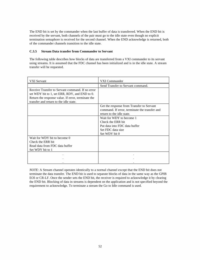
C.3.5 Stream Data transfer from Commander to Servant
The following table describes how blocks of data are transferred from a VXI commander to its servantusing streams. It is assumed that the FDC channel has been initialized and is in the idle state. A streamtransfer will be requested.
VXI Servant VXI Commander
Send Transfer to Servant command.Receive Transfer to Servant command. If no errorset WDY bit to 1, set ERR, RDY, and END to 0.Return the response value. If error, terminate thetransfer and return to the idle state.
Get the response from Transfer to Servantcommand. If error, terminate the transfer andreturn to the idle state.Wait for WDY to become 1Check the ERR bitPut data into FDC data bufferSet FDC data sizeSet WDY bit 0
Wait for WDY bit to become 0Check the ERR bitRead data from FDC data bufferSet WDY bit to 1
.
.
.
.
.
.
NOTE: A Stream channel operates identically to a normal channel except that the END bit does notterminate the data transfer. The END bit is used to separate blocks of data in the same way as the GPIBEOI or CR-LF. Once the sender sets the END bit, the receiver is required to acknowledge it by clearingthe END bit. Blocking of data in streams is dependent on the application and is not specified beyond therequirement to acknowledge. To terminate a stream the Go to Idle command is used.

53
C.3.6 Abort Flag Usage
It is assumed that a normal transfer is requested.
Error Generator Error Detector
Wait for ownership of the FDC bufferSet ABT bit to 1Pass FDC area to error detector with RDY orWDY
Poll RDY or WDY for buffer ownership transferCheck ABT bit for 1If ABT = 1 then set ABT to 0. If this is a Normalchannel also set RDY, WDY and END bits to 0
Wait for ABT bit to become 0Return to idle stateReport error through normal instrument specificmechanisms
Return to idle state
The FDC transfer can be aborted by either the VXI servant or VXI commander by setting the ABT bit to 1during a normal transfer. While the VXI servant or VXI commander is polling for RDY or WDY, itshould check the ABT bit to determine whether error has occurred. Once the Error Generator has set theABT bit to 1, it is required that the Error Detector acknowledge detection of ABT bit being asserted.
C.3.7 Channel Termination Example
Commander Servant
Send Channel Close command to servantreceive Channel Close CommandCheck that channel is currently openCheck that channel is currently idle if this is anormal channel.If open and idle close the channelReturn status word
Receive status wordIf success invalidate channel
If success invalidate channel


D. Message Transfer Protocol
D.1.1 Introduction
Message transfer protocol (MTP) provides an alternate mechanism for transporting commands andresponses into and out of VXI modules. It does this by standardizing the utilization of an input and outputFDC stream channel for communication. Modules which support MTP switch from Byte TransferProtocol (BTP) to MTP when the MTP Initiate Word Serial command is successfully executed.
After MTP is initialted, all communicaiton with the module is directed through MTP. If the MTP channelis terminated, the module switches back to Byte Transfer Protocol. MTP provides a more efficientmechanism to communicate messages within a VXI system.
MTP utilizes two standard FDC stream channels. Channel 4 is defined as the command channel overwhich instrument commands are sent. The command channel utilizes the Transfer to Servant protocol.Channel 6 is defined as the response channel over which instrument responses are sent. The responsechannel utilizes the Transfer to Commander protocol. MTP may also be initiated using channel pairs.When channel pairs are used the command channel is on 4 and 5, the response channel is on 6 and 7.
D.1.2 MTP Establishment and Termination
Message Transfer Protocol is established by initilalizing the MTP channels and then sending the MTPInitiate VXI Word Serial command to the servant. If the servant supports MTP it will disable ByteTransfer Protocl (DIR & DOR = 0), initialize MTP communications and return a success response. IfMTP establishment fails, BTP remains enabled, the MTP channels remain in the idle state and an errorresponse is returned.
MTP termiantion returns the communications back to Byte Transfer Protocol. MTP Termination occurswhen the servant executes a MTP Terminate command. The servant returns the MTP channels to the idlestate, re-enables the Byte Transfer Protocol and returns a success response. Both the MTP Initiate and theMTP Terminate commands execute the functionality of the Word Serial CLR command as part of theiractions. This ensures that no communications are split between BTP and MTP.
D.1.3 MTP Communication
MTP commands can be sent to the servant when it is in either CONFIGURE or NORMAL state. However,no messages may exist in CONFIGURE state. Commands and responses may only be communicated whilein NORMAL state. Reciept of an ENO or ANO when MTP is active will transition the servant toCONFIGURE state and flush the MTP input and output buffers. This does not terminate MTP.
Once MTP is established, all commands and responses are communicated through MTP. All VXI Wordserial commands are still functional except the Byte Available (BAV), Byte Request (BRQ) and theTrigger command. The CLR command operates in the same manner in MTP as it does in BTP. Triggercommands are sent using the MTP Trigger command.
Transferring instrument commands to the servant is accomplished in the normal manner for streamchannels. The commander places a message in the FDC buffer, sets the data size in the channel header,sets the end bit appropriately and passes the FDC area to the servant. The servant retrieves thisinformation from the FDC area and passes the FDC area back to the commander.
When a servant has a response, it places the response in the FDC buffer, sets the data size field to thenumber of bytes in the response, sets the end bit appropriately and passes the FDC area to the commander.

56
The commander receives ownership of the FDC area, retrieves the data and passes the buffer back to theservant.
Because the VXI Trigger command must be sent synchronouly to the command stream, MTP defines atrigger command which is sent through the MTP command channel. The MTP trigger command is sentby setting the trigger bit in the FDC header to a one in the command channel and passing the FDC area tothe servant. The MTP Trigger command does not transfer any data so the buffer and size parameters haveno meaning. The commander must ensure that the trigger bit is cleared before sending susequentcommands.
The commander should maintain a timeout timer on both the command and response channels. Thecommand channel might time out if the servant has not returned the FDC area within the timeout period.The response channel might time out if the response FDC area is not passed to the commander within thetimeout period. To reset the command and response channels back to a ready state, the commander shouldsend the Word Serial CLR command to the servant and then return the MTP response buffer to theservant. The CLR command will cause the servant to return the command buffer.
D.1.4 MTP General Requirements
RULE D.1.1MTP SHALL only utilize the random mode of access for the FDC buffer area.
D.1.5 MTP Commanders
MTP commanders should ensure that the MTP channels are initialized before Message Transfer Protocolis requested.
RULE D.1.2An MTP commander SHALL initialize FDC channels 4 and 6 before sending the MTP initiatecommand. If MTP channel pairs are used then the commander SHALL also initialize the FDCchannels 5 and 7 before sending the MTP channel Initiate command.
OBSERVATION D.1.1From the time MTP is initiated until it is terminated, DIR and DOR remain false. Thecommander can not send the Byte Transfer Protocol commands BAV, BRQ or the Word Serailcommad Trigger to the servant.
RULE D.1.3From the time MTP is initiated until it is terminated, a commander SHALL NOT send the FDCcommand Goto Idle to channels engaged in MTP protocol.
RULE D.1.4A commander engaged in MTP SHALL only send commands on channel 4 or channel 4 and 5for channel pairs.
RULE D.1.5A commander engaged in MTP SHALL only request a response on channel 6 or channel 6 and 7for channel pairs.

57
D.1.6 MTP Servants
RULE D.1.6When a MTP servant executes the MTP Initiate command, it SHALL transition standardchannel 4 (4/5) to stream transfer to servant and standard channel 6 (6/7) to stream transfer tocommander state. Before returning the status word, the servant SHALL execute the actionsdefined by the Word Serial CLR command and pass the FDC area of the command channel(s) tothe commander by setting the appropriate header bits.
RULE D.1.7When a MTP servant executes the MTP Initiate command successfully, it SHALL set DIR andDOR to false (0) before returning the success status word.
When the MTP servant has response data, it places all or a portion of the response in the response channelFDC area and passes the buffer to the commander. The response channel FDC area ownership will remainwith the commander until the user application retrieves all of the response data. When the response datahas been read by the commander, the response channel FDC area is passed back to the servant.
From the servants perspective, the response has been delivered once all of it has been passed to thecommander via FDC buffers. Once delivered, the servant is ready to accept new commands and querys.
RULE D.1.8When a servant receives a Word Serail CLR command, it SHALL return the MTP FDC area(s)for the command channel to the commander.
When the MTP commander sends the trigger command to the servant it sets the trigger bit in the FDCheader and passes the FDC area to the servant. The servant should check the trigger bit each time itreceives a command buffer. When the trigger bit is set, the buffer size and buffer data have no meaningand should be ignored.
RULE D.1.9When a MTP servant is passed the FDC area for standard channels 4 or 5 it SHALL check thetrigger bit in the FDC header. If it is set, the servant SHALL ignore the buffer size and bufferdata in the FDC area and execute the VXI trigger function as defined by the Word Serial Triggercommand and then pass the FDC area back to the commander.
RULE D.1.10When a MTP servant receives the MTP Terminate command it SHALL execute the actionsdefined by the Word Serail CLR command, enable Byte Transfer Protocol and return the successresponse.

58
E. MTP Commands
MTP SupportedThis command is used to determine MTP support.
The syntax of the MTP Supported command is defined in the following table.
Bit #15 14 13 12 11 10 9 8 7 6 5 4 3 2 1 01 0 0 1 1 1 1 1 0 0 0 0 1 1 1 1
A single response word is placed in the Data Low register in the following format:
15 14 13 12 11 10 9 8 7 6 5 4 3 2 1 0Status 1 1 1 1 1 1 1 1 1 1 1 1
Status: This flag indicates status of the MTP Supported command. F16 - MTP supported. 716 - ERROR - MTP not supported.

59
MTP InitiateThis command is used to initiate MTP transfering communications from Byte Transfer Protocol toMessage Transfer Procotol.
The syntax of the MTP Initiate command is defined in the following table.
Bit #15 14 13 12 11 10 9 8 7 6 5 4 3 2 1 01 0 0 1 1 1 1 1 0 0 0 0 1 0 EX PR
PR : use channel pairsEX: use extended channels
A single response word is placed in the Data Low register in the following format:
Bit #15 14 13 12 11 10 9 8 7 6 5 4 3 2 1 0
Status 1 1 1 1 1 1 1 1 1 1 1 1
Status: This flag indicates status of the MTP Initiate command. F16 - No errors detected. 716 - ERROR - MTP not supported. 616 - ERROR - MTP pairs not supported. 516 - ERROR - MTP channels not initialized and in the Idle state. 416 - ERROR - MTP already engaged.
The channels can be either standard or extended type. Channels used by MTP must be initialized beforethe MTP Initiate command is sent. Channels 4 and 6 must always be initialized. Channels 5 and 7 mustbe initialized if the PR bit is set to 1.
When the servant receives the MTP Initiate command it should:• determine that channels 4 and 6 (5/7) have been initalized.• execute the actions of a Word Serial CLR command.• transition FDC channel 4 (4/5) to transfer to servant. transition FDC channels 6 (6/7) to transfer to
commander.• terminate Byte Transfer Protocol setting DIR and DOR false.• Return the execution status of the MTP Initiate command.

60
MTP TerminateThis command is used to terminate MTP returning communications to Byte Transfer Protocol.
The syntax of the MTP Terminate command is defined in the following table.
Bit #15 14 13 12 11 10 9 8 7 6 5 4 3 2 1 01 0 0 1 1 1 1 1 0 0 0 0 1 1 0 0
A single response word is placed in the Data Low register in the following format:
Bit #15 14 13 12 11 10 9 8 7 6 5 4 3 2 1 0
Status 1 1 1 1 1 1 1 1 1 1 1 1
Status: This flag indicates status of the MTP Terminate command. F16 - MTP successfully terminated. 716 - ERROR - MTP not currently engaged.
MTP Terminate is the only provided method for returning communication to Byte Transfer protocol.
When the servant receives the MTP Terminate command it should:• Complete any executing commands discarding any output messages.• Execute the actions of a Word Serial CLR command.• Return the MTP channels to the Idle state.• Do servant specific termination functions.• Switch to Byte Transfer Protocol.• Return success status of the MTP Terminate command.