virtual machining chapter manufacturing technology handbook
TRANSCRIPT

Metadata of the chapter that will be visualized online
Chapter Title Virtual MachiningCopyright Year 2014Copyright Holder Springer-Verlag LondonCorresponding Author Family Name Liu
ParticleGiven Name PeilingSuffixOrganization Singapore Institute of Manufacturing
TechnologyAddress 71 Nanyang Drive, Singapore,
638075, SingaporePhone (+65) 6793-8356Fax (65) 6793-8356Email [email protected] http://www.simtech.a-star.edu.sg/
Author Family Name ZhuParticleGiven Name Cheng-FengSuffixOrganization Singapore Institute of Manufacturing
TechnologyAddress 71 Nanyang Drive, Singapore,
638075, SingaporePhone (65) 6793-8336Fax (65) 6791-6377Email [email protected]
Abstract Virtual machining simulates NC code to discover errors, without atime consuming trial run or online debugging on real machine tool.Since machining is a material removal process that will deform theworkpiece geometry with cutting, the traditional rigid geometrical modelcould not be used to describe the in-process status of workpiece, whichchanges shape continually. The evolution of deformable workpiecemodel from the 2D sections to 3D representations revolutionized notonly the machining industry, but also pioneered the digital manufacturingage with virtual manufacturing. This chapter traces back the history ofCNC simulation, analysis of the different CNC machining models, testedwith application examples, and lists different CNC verification industryapplications for the last 30 years. Working towards a vision of pervasivemodelling and simulation, a unified voxel-based in-process geometrymodel for multiple-machining and 3D printing simulations is discussed

with industrial applications of composite material plating simulation.The virtual machine tool, which includes material removal animationand machine kinetic movement, can be controlled with a virtual CNCcontrol panel and equipped with virtual jigs and inspection tools, such asdial indicator and wiggler, for immersive training of a young machinist.Towards a competitive sustainable manufacturing future, pervasiveapplications of virtual machining are not only technologically possible,but also make business sense, in this high material and energy cost world.

Virtual Machining
Q1 Peiling Liu* and Cheng-Feng ZhuSingapore Institute of Manufacturing Technology, Singapore, Singapore
Abstract
Virtual machining simulates NC code to discover errors, without a time consuming trial run or onlinedebugging on real machine tool. Since machining is a material removal process that will deform theworkpiece geometry with cutting, the traditional rigid geometrical model could not be used todescribe the in-process status of workpiece, which changes shape continually. The evolution ofdeformable workpiece model from the 2D sections to 3D representations revolutionized not only themachining industry, but also pioneered the digital manufacturing age with virtual manufacturing.This chapter traces back the history of CNC simulation, analysis of the different CNC machiningmodels, tested with application examples, and lists different CNC verification industry applicationsfor the last 30 years. Working towards a vision of pervasive modelling and simulation, a unifiedvoxel-based in-process geometry model for multiple-machining and 3D printing simulations isdiscussed with industrial applications of composite material plating simulation. The virtual machinetool, which includes material removal animation and machine kinetic movement, can be controlledwith a virtual CNC control panel and equipped with virtual jigs and inspection tools, such as dialindicator and wiggler, for immersive training of a young machinist. Towards a competitive sustain-able manufacturing future, pervasive applications of virtual machining are not only technologicallypossible, but also make business sense, in this high material and energy cost world.
Introduction
Virtual manufacturing is a new and emerging concept to integrate different areas of manufacturingby using computer technology for creation and execution of virtual models. Virtual manufacturing isdefined as a computer-based system, which consists of evolving models of manufacturing systemsand processes, and is exercised to enhance one or more attributes of the real system. Manufacturingas a whole is a very complex system consisting of various interacting, interrelated, andinterdependent subsystems and processes. Virtual machining, a small building block in the com-prehensive virtual manufacturing system invented in the 1960s, pioneered virtual manufacturingwith material removal process visualization long before its coronation in the 1990s.
Machining had been a low productivity manual operation until the invention of numerical control(NC) in the 1950s, when the hand wheels and levers were replaced by punch tapes control, similar totelegraphs at that time. These early servomechanisms were rapidly augmented with computers sincethe 1960s, the computer numerical control (CNC) machine tools have revolutionized the machiningprocess and radically changed the manufacturing industry. Complex 3D shapes are relatively as easyto cut as the plane face, and manual polishing works have been dramatically reduced.
*Email: [email protected]
Handbook of Manufacturing Engineering and TechnologyDOI 10.1007/978-1-4471-4976-7_16-1# Springer-Verlag London 2014
Page 1 of 54
In 1958 MIT published its report on the economics of NC. They concluded that the tools werecompetitive with human operators, but simply moved the time from the machining to the creation ofthe tapes. NC programming became a bottle neck in machining. Automatically programmed tool(APT) language was developed to generate instructions for NC control during the late 1950s andearly 1960s. It was widely used into the 1970s and is still a standard nowadays. Since APT wascreated before graphical user interfaces (GUI) and computer graphics (CG) were available, it relieson text to specify the geometry and process. Again, this is a highly skilled manual script writing thatslowed NC machining, especially for high volume low mix parts, where a lot of new NC programswere needed. Computer aided manufacturing (CAM) was developed to quicken and automate thisprocess, where the shape could be defined by computer aided design (CAD) software. TheCAM/CAD system have proliferated CNC machine tools since the 1980s.
An NC program has thousands of lines of tool movement instructions that may contain errors.Following these instructions, a CNCmachine tool will move blindly, without any check on gauging,overcut or cutting force. It is impossible to verify codemanually, thus virtual machining can virtuallytrial run NC code in a computer, to verify NC code and replace trial cut that is time consuming anddangerous.
Virtual machining, visualization of material removal of various machining processes, isa geometrical modelling process that realistically simulates the setting up and running of an actualmachining operation. First, the user specifies the stock from which the part will be cut, either byentering dimensions into the software or importing a CADmodel. Then, after parsing NC code withthe selected cutter, NC toolpath backplot can display tooltip trace against design model, highlightinggrammar error and errant movement. NC simulation automatically simulates the motion of the toolremoving material from the stock. The programmer can watch the material removal process and seedetails of how each cut changes the shape of the part, which is a deformable in-process geometricalmodel. This eliminates having to try to imagine how cuts from the current operation will affectsubsequent operations, which will help to plan for the next operation. NC analysis will compare thisin-process model against the target design and display the remaining stock with a coloured map andreport. Since the NC programming error was haunting machinist from the beginning, this was alsocalled NC verification, a short name for machine tool numerical control code verification.
Since machining is a material removal process that will deform the workpiece geometry withcutting, the conventional CAD geometrical model cannot be used to describe the in-process status ofworkpiece which changes shape continually. The evolution of deformable workpiece model fromthe 2D sections to 3D representations revolutionized not only the machining industry, but alsopioneered digital manufacturing age with virtual manufacturing. Various in-process geometricalmodels and their applications are discussed in this chapter. Virtual machine tool, which includesmaterial removal animation and machine kinetic movement, can be controlled with a virtual CNCcontrol panel and equipped with virtual jigs and inspection tools, such as dial indicator and wiggler,for immersive training of a young machinist.
Recently it has expanded from geometrical modelling into process modelling, including themachine dynamic and FEM cutting simulation, with in-process geometrical model as its foundation.In geometric modelling, cutter-workpiece engagements are extracted to support force prediction inprocess modelling. In process modelling, the physics of the machining process, such as cuttingforces, torque and power, are predicted by integrating the laws of the metal cutting process. Based onthese predictions, process parameters can be optimized for productivity.Methodologies in geometricmodelling for cutter-workpiece engagement extractions require a large number of calculations,however, the robustness and computational stability of these approaches is a significant challenge,which will be covered in another two chapters of this handbook.
Handbook of Manufacturing Engineering and TechnologyDOI 10.1007/978-1-4471-4976-7_16-1# Springer-Verlag London 2014
Page 2 of 54

Virtual Machining Industry Landscape
Virtual machining has been a vivid academic research theme of virtual manufacturing since the1990s, together with the low cost PC, internet, virtual reality (VR) andOpenGL. VR has been widelyexplored as a means of virtual machining with many academic research prototypes. JAVD 3D is usedto distribute simulation image over the internet. STEPNC simulation is also a part of STEP research.As there are many review and survey papers on virtual machining academic research availableonline (AbdulKadir et al. 2011), this chapter focuses on industrial applications which are commer-cially available and technologically stable to engineers and machinists.
Virtual machining is so important that the CAD/CAM developers were eager to develop inte-grated CNC simulation into their system, with great success on native CAD machine tool kineticssimulation, internal NC toolpath backplot can be displayed as different doted-solid colour lines, andpartial success of a 2D in-process workpiece model, which is always deformable since the geometrychanges with every cutter move. Different fromCADmachine frame and toolpath, the 3D in-processworkpiece could not be modelled with conventional CAD B-rep solid modeller, such as ACIS orParaSolid. Initially CAD/CAM geometry model was tested to model machining process but failed,since the in-process geometry of workpiece is deforming but conventional CAD model isstatic. How to develop an in-process geometrical model (IPM) that could simulate the deformingworkpiece has been a research challenge, which has attracted great academic research interests sincethe 1980s. There is a vivid research theme of a smart machining system (SMS), which builds IPMinto a brain of intelligent machining for CNC machine tool.
Professor Donald Esterling pioneered NC verification, leading the way as a variety of OEMpartners incorporated this technology into their products. N-See™ (Predator VIRTUAL CNC™)was the first volumetric based solid model NC verification program, raising the bar for speed andaccuracy. While on the engineering faculty of George Washington University, he initiateda manufacturing program in the mid-1980s funded by a $2 M grant from IBM. Esterling hasreceived research funding from NASA, NIST, NSF, NATO, US Air Force and the US ArmyResearch Office. He has been awarded several prestigious and highly competitive Small BusinessInnovative Research (SBIR) grants. He has a successful track record of moving research projectsfrom the lab to commercial applications.
While he worked with McDonnell Douglas Corporation, Occidental Petroleum and MCS asa CAD/CAM consultant, Jon Prun accumulated abundant experience of computer software, com-puter graphics, mathematics and digital control technology. Having realized that there was a greatneed of digital control simulation technology by manufacturing, he established a company namedCGTech in 1988 to develop a suite of digital control simulation software VERICUT™. One afteranother, CGTech partnered with Unigraphics, Dassault Systems and PTC to get support from theserenowned CAD/CAM companies. VERICUT™ was first run in UNIX system computers based onSun workstation, and then upgraded to PCs and other workstations such as HP, IBM and DE-C. Nowadays CGTech has many branches worldwide, and almost all the customers are runningVERICUT on PCs.
There was a time when CAD/CAM components were developed and marketed as an independentsoftware module, such as ACIS, which was started as object oriented CAM components.MachineWorks™, which is a spinoff from LightWork UK, pioneered the market for embeddedsimulation in the mid-1990s when NC simulation was a “nice-to-have”, by offering the first truehistory based solid model simulation, which has been patented worldwide. MachineWorks’ simu-lation solution allowed CAM software producers to provide integrated simulation as a core
Handbook of Manufacturing Engineering and TechnologyDOI 10.1007/978-1-4471-4976-7_16-1# Springer-Verlag London 2014
Page 3 of 54

functionality in their applications. Embedded simulation soon became a “must-have” for main-stream CAM applications.
However, embedded NC simulation could only discover internal NC toolpath errors, which is inAPT format. This internal NC toolpath is post processed into machine control data (MCD), such asG/M code. There are much more errors after post processing and human editing, where theindependent machine control code verification package is still a must.
Furthermore, the history based virtual machining will slow down along with the cutting history,since the method records toolpath into voxel cells so it can zoom without losing resolution. RecentlyMachineWorks claimed they have removed history from their model and sped up the simulationgreatly.
ModuleWorks™ from ModuleWorks provides a complete CAD/CAM component solution withhigh performance toolpath simulation and NC verification. The toolpath simulation componentsupports milling, turning and mill/turn applications with full machine simulation, stock removalverification and toolpath analysis. ModuleWorks™ toolpath simulation will identify problem areassuch as potential collisions, gouges or over travel and allow correction prior to NC code generation.It is viewed bymany as an essential aspect of the CAM process. NC simulation library provides stateof the art technology and is well proven and in use with many of the leading CAM software solutionsaround the world today. The simulation component can be quickly implemented using the easy touse API. ModuleWorks™ provide full kinematic machine simulation with comprehensive collisionand axis limits checking. A full kinematic machine builder supports mills, lathes, mill/turn, robotsand CMM machines with support for an unlimited number of axes. NC simulation and toolpathverification component also provides fast, high accuracy verification of stock removal for mill, turnand combined mill/turn applications. NC simulation also offers a full range of toolpath analysis toolsfor many critical aspects of toolpath behaviour such as segment length/type, feedrate and heightallowing toolpath to be refined for optimum finish and quality. NC simulation tools are independentof the toolpath generation CAD/CAM components and can be used with any toolpath or backplotNC code.
SIMNC from BinarySpaces produces 3D simulation of complex multi-axis machine tools,including collision detection, material removal and other non-cutting processes. The SIMNC CoreAPI, the foundation of the entire product line, is built using the latest software architecture, whichoptimizes its use of memory and CPU power – allowing the product to run on-line on a machine toolcontrol or off-line on a stand-alone PC. This modern architecture supports parallel processing thatmaximizes graphics performance on 64-bit and/or multi-core computers. SIMNC includesa machine tool builder to aid in defining the computer representation of the machine tool. TheSIMNC control emulator allows the simulation engine to run off-line directly from the end user’sG-code part programs, while the SIMNC part set-up aids the end-user in defining the cutting toolsand fixtures related to each individual CNC program.
Kinetic Simulation of Machine Tool
In advanced virtual machining systems, it is possible to include other elements such as machineframe, fixtures, clamps and tool holders. These are required for collision detection. In some packageslike VERICUTand NCSIMUL, the entire machine also can be simulated to visualize the kinematics;this will be particularly very useful during 5-axis machining, where the collision of tool holder andfixture may destroy machine spindle.
Handbook of Manufacturing Engineering and TechnologyDOI 10.1007/978-1-4471-4976-7_16-1# Springer-Verlag London 2014
Page 4 of 54

Machine Tool ModelAmachine tooling system is made of rigid parts (frame, jig, fixture and toolholder), wearable cutter,and deformable workpiece, which is continuously changing and has to bemodelled with voxel basedin- process model (IPM). Voxel based IPMs are deformable and expensive in terms of computermemory, in line with the size of the workpiece. A machine tool frame, including jig and fixture,could be 10 m long and wide, so it is too expensive to model them in voxel model. During themachine simulation, only the parts interference is checked with a simple and quick collision checkalgorithm, without an expensive material removal calculation.
Generally, the geometrical representation scheme for machine tool is the same as conventionalCAD, so it is possible to simulate the entire machine motions with conventional CAD/CA-M. Building the machine frame geometrical models, kinetic constrain and control are dauntingtasks that are usually done by CAD/CAM developers. However, the geometrical representationscheme for material removal is different from conventional CAD, so it is not possible to simulate thematerial removal process with conventional CAD/CAM. The material removal process is simulatedoutside CAD/CAM with third party applications such as VERICUT. Furthermore, conventionalCAD/CAM systems have their own interactive graphical user interface (GUI) for quick creating andediting of a geometrical design model and drawing. It is difficult to customize this GUI to manuallyoperate a virtual CNC machine tool, which functions more like a computer game.
The simulation of material removal on the workpiece and simulation of machine kinematics canbe done in different sessions (CAD/CAM for machine motion and third party applications formaterial removal) or simultaneously in a single third party application session, which is morerealistic and good for machinist training.
Since machine tool frame and jigs-fixtures are rigid static geometry, they could be modelled withconventional CAD and exported as triangular polyhedral mesh by stereo lithography (SLA) formatwith file extension of STL, which is quite similar to VRML format. Figure 1 shows the frame modelbuilt up of a 3 axis milling machine, which starts with X axis, Z axis and ends with Y axis.
A comprehensive machine tool system also includes the opaque machine cover, transparent glasswindows, movable doors, operateable handle/lever/pedal, measurement indicators, and virtual CNCcontrol panel, which is critical for operational training. Figures 2 and 3 depict two models of virtualmachine tools: CNC mill and CNC lathe, that are manually CNC operateable as a real machine.More than a real machine tool, the virtual machine tool can be zoomed from different angles inmultiple viewports highlighted with translucent colours for enhanced learning effects that are morelike an educational computer game.
Conventional CAD/CAM system is suitable for machine tool simulation with internal NCtoolpath, which is cutter location (CL) data that is generated inside the system, usually in APT
Fig. 1 Virtual machine in X axis, XZ axis and XYZ axis
Handbook of Manufacturing Engineering and TechnologyDOI 10.1007/978-1-4471-4976-7_16-1# Springer-Verlag London 2014
Page 5 of 54

format that is an industry standard. However, the post processing converts APT into machine controldata (MCD) with geometry transformation and CNC controller specification, a lot of things could gowrong at this stage. For example, table plus table and table plus head 5-axis configurations are totallydifferent. Even with the same configuration, FANUC and Siemens need different codes for com-pensation. So there is a need to simulateMCD code such as GE FANUCG/M code, Heidenhain G/Mcode or Heidenhain conversational code, so the machine tool will move according to real situation.Reverse post processing will translate MCD back into APT format.
Fig. 2 Virtual CNC mill
Fig. 3 Virtual CNC lathe
Handbook of Manufacturing Engineering and TechnologyDOI 10.1007/978-1-4471-4976-7_16-1# Springer-Verlag London 2014
Page 6 of 54

Reverse Post-processing MCD back to APT ToolpathThe reverse post-processor reads, analyses NC program and translates it to internal NC toolpath inAPT format, as described in flowchart Fig. 4. It supports structured programs, variables, cycles andmacro calls for a wide choice of commercially available NC controllers.
Analysis and parsing MCD data, such as G/M code, especially for a manually written program, iscritical to avoid time-consuming debugging on machine tool control panel, when the machine isrunning but without production. For most CAM generated G/M code, the grammar error is nota concern anymore, so it is possible to bypass grammar check and achieve faster NC toolpathbackplot. However, parsing is a critical step for CNC training, where a new trainee may write strangecode and try to run it on machine tool.
CNC control panel is equipped with a keypad for text input. Virtual control panel must parse thismanual input and simulate the action with warning signals. The CNC controller is a fully functionalhigh level computer language interpreter, so is the virtual CNC controller. There are variables,formulas, subprogram and mathematic functions within a machine control code script.
Automatically programmed tool (APT) was a high-level computer programming language used togenerate instructions (MCD) for NC machine tool before CAD/CAM revolution. Now CAMsoftware replaced APT for toolpath generation but still kept it as internal CL data format to expressinternal NC toolpath in ASCII text. Most CAM systems can save the internal NC toolpath as APTformat and use a third party post processer (such as ICAM) to generate the machine tool specificMCD, such as FANUC 16M G/M code. Since APT is the internal NC toolpath format there is noreverse processing step in reading APT text data file into the internal NC toolpath.
Most virtual machining systems accept cutter path in the form of NC code specific to the CNCmachine or in the form of a generic format APT. If the input is NC code specific to a CNC machinetool, one would additionally require a machine tool data file that provides its process, kinematic andsyntactic details and cutter data file. An NC reverse processor synthesises them to generate thecorresponding CL file. Note that all the other algorithms further use only APT CL data file.
This process requires that the reverse post processer is properly configured for the particularsyntax of the NC language and the particulars of the CNC control. These configurations are machinespecific. For example, the Fanuc 10A file contains a complete definition of the syntax and
Fig. 4 Reverse post processing flowchart
Handbook of Manufacturing Engineering and TechnologyDOI 10.1007/978-1-4471-4976-7_16-1# Springer-Verlag London 2014
Page 7 of 54

conventions used with this control. With multi-axis machines this process also requires that themachine definition is properly configured for the particular style of multi-axis machine.
The reverse post-processor configuration file defines the relationship between G&M codes in theNC program and the associated functionality. This is the same process that takes place in the controlitself where each NC code is interpreted before taking effect. G & M codes are identified throughfixed patterns. The reverse-post will identify patterns by comparing NC program contents with thereverse post’s pattern definitions.When a pattern is identified, a specific functionality is associated toit, and then the actual output tool motion or NC simulation is generated and expressed with APTformat.
Toolpath BackplotAPTandMCD are text based high computer language scripts that are difficult to visualize against thepart geometry, therefore, the obvious first idea was to couple the NC to a plotter that would trace onpaper the trajectory of the cutting tool. The drawing would immediately reveal an eventual mistake.Nowadays the screen replaced the plotter but this NC toolpath preview function is still called back-plotting, the oldest and most popular NC code verification. Only after the simulation shows theprogram to be devoid of gross mistakes, the real machine can be used. Toolpath backplot follow thecutter tip movement and display as doted (G0 fast move) or solid (G1 cutting) lines with differentcolours, which could be used to different operations. Good backplot functions could highlightcurrent position, operation and cutter information. Cutter move animation is also a vivid simulationof cutter movement. Modern backplot toolkit works together with NC code text editor, so the NCcode editing is visualized instantly, and doubles as an NC code learning tool for students.
The traces of tooltip are imagery lines in space but are useful in visualizing tool movement, sothese traces are also modelled as toolpath, even though in reality there are no such lines. The cutterand tool holder can move forward and backward with tip on the toolpath, this vivid animation can beused for NC programming and visual gauging check.
The classic double link list data structure is used for the toolpath model that is modelled in Fig. 5.The double pointer enables the cutter to move forward or backward without looping through every
Fig. 5 Toolpath data structure
Handbook of Manufacturing Engineering and TechnologyDOI 10.1007/978-1-4471-4976-7_16-1# Springer-Verlag London 2014
Page 8 of 54
node. To delete and add one node is easy compared with an array data structure. This data structurealso works for extended Z buffer and extended Z map, where both need to delete and modifyelements in real time.
Material Removal Simulation of Cutting
UNIX based CADGraphicsWorkstation introduced a separate graphics card and low cost large CRTdisplay, where the depth and colour buffers are used to store screen pixels. The painter’s algorithm isused to draw animation pictures on screen. Virtual machining pioneers extended this depth bufferwith multi value so an animated cutter can move through a screen and paint a “negative” trace, orerase something, just like cutting the stock from workpiece. This trick is also called extendedZ buffer method that is view angle dependent. The extended Z buffer method runs very fast since it isdirectly updating graphic memory without view transformation which is a time consuming algo-rithm inside the CPU. The extended Z buffer picture is pixel perfect with vivid details, since everypixel is refreshed with a cutter colour. Some virtual machining systems are still animating materialremoval with this technique, with another more precise in-process model as database. However,directly rendering in-process model is a more popular approach, where the workpiece can be rotatedand zoomed during cutting animation.
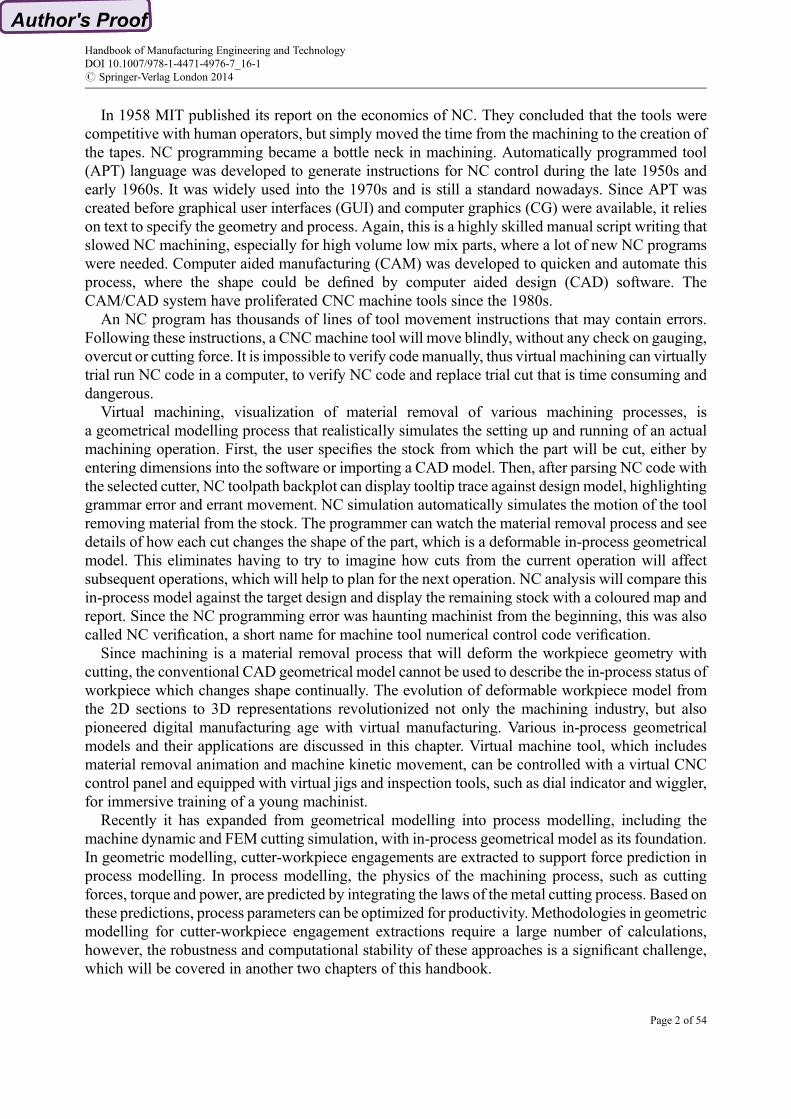
This method projects the workpiece and cutter onto the display screen and gets an array of linklists of an element that has a near Z value and a far value, a stick with the size of pixel. The arraycorrelates to the size of display window. The cutter image also has near and far Z values that will beused to compare with the workpiece image. The cutter moves through this array of sticks and cutsthrough them in Fig. 6.
If the cutter and the element never touch, there is no change in the extended Z buffer in Fig. 7. Theframe buffer is updated with this background image; this is to erase the previous cutter image at theprevious position. The cutter image is painted on the screen with current position to show a cuttermovement. Exactly a movie trick, the user sees a smooth move of cutter along the toolpath.However, the developer usually only updates a small area around the previous cutter position tospeed up display speed. Some even used Boolean operation for colour buffer. These algorithms work
Fig. 6 Extended Z buffer cutting animation
Handbook of Manufacturing Engineering and TechnologyDOI 10.1007/978-1-4471-4976-7_16-1# Springer-Verlag London 2014
Page 9 of 54

for an old time computer that is slow and expensive. How to show a smooth cutter movement hasbeen a research theme for a long time.
If the cutter is cutting an inside element that is hidden from the user as shown in Fig. 8, theextended Z buffer modifies the inside element with the cutter colour. The cutter image is partiallyblocked and trimmed by the outside element so the user can see the cutter plunge into the material.
If the cutter is cutting on the near end of an outside element, the user can see the material removalprocess. If the cutter is cutting on the far end of an outside element, the user can see the cutterplunging into the workpiece. If the cutter is cutting both the near and far end of the element as inFig. 9, this element will be removed and the user can see the previous hidden inside element, whichbecomes the outside element at this moment.
The swept volume of the cutter is critical for material removal animation, where the swept volumeis subtracted fromworkpiece model continuously. This is a famous computational geometry quest sothere are many academic research works on how to generate this swept volume for 2 axis, 3 axis and
Fig. 7 Air cutting cutter movement animation
Fig. 8 Cutting inside element
Handbook of Manufacturing Engineering and TechnologyDOI 10.1007/978-1-4471-4976-7_16-1# Springer-Verlag London 2014
Page 10 of 54

5 axis milling, where the cutter position moves and cutter angle swings. For example, an end milllinear move in the XY plane can sweep through one box plus a half cylinder, a Boolean operationbetween this swept volume and workpiece model subtracts this swept volume fromworkpiece whichdeforms the workpiece model, which will change shape with cutting, so it is a deformable geometrymodel.
The extended Z buffer algorithm is good for animation but it is view angle dependent. Oncea simulation starts, the view angle and zoom factor cannot be changed, otherwise the simulation hasto start over from the beginning. The extended Z buffer in Fig. 10 can be saved as a geometry modeland measured against the design model. However, it is precise only in the view direction, so it isnecessary to simulate in different angles for more reliable results.
Workpiece In-process ModelThe stock, the machining allowance, is the material to be machined. The workpiece is the targetmachined part with stock material on surface, which may be a forged or cast part with the machiningallowance. The initial workpiece is a block produced from forging, casting or rolling process. Thegeometry of the workpiece will change after each machining operation. This evolving geometry ofthe workpiece is defined as an intermediate or in-process model.
Fig. 9 Remove outside element and expose inside element
Fig. 10 Extended Z buffer in-process model
Handbook of Manufacturing Engineering and TechnologyDOI 10.1007/978-1-4471-4976-7_16-1# Springer-Verlag London 2014
Page 11 of 54

The deformable in-process model (IPM) represents the state of the workpiece at each step in themachining process. It is a 3D geometrical construct that reflects the results of the machiningoperations. This model allows the user to visually verify that the machining operations have beendefined accurately and that their sequence is correct. It can be automatically re-generated when thereare changes in the product design, machining parameters or sequence of the operations.
The in-process model is a must for the next step cutting plan. The in-process model is onlya conceptual model for most of the commercial CAM systems, there is no in-process model that canbe output and stored in a database. In a traditional NC programming environment, a significantamount of time is spent trying to visualize the in-process model through various process stages. Thein-process or evolving model is used in subsequent setups and provides immediate feedback on theprogress being made. Being able to view in-process geometry, while creating toolpath and processplan, greatly reduces the chances of error in both setup and machining. It also helps in designingfixtures, positioning clamps and so on.
Host CAD B-rep In-process ModelThe B-rep is a typical CAD geometry model. The shape of a part is represented in a point-edge-faceschema. The previous studies showed that NC cutting result could not be modelled in B-rep becauseof the complexity of the cutting model. The first choice of IPM should naturally be the geometrymodel B-rep used in commercial CAD system. The benefits of using the same geometry model forCAD as the IPM are obvious. The CAD geometry model is matured and available through CADdevelopment kit, so there is little need to develop a new geometry model kernel. Sharing a commongeometry model with CAD, the IPM facilitates seamless integration of CAD-CAPP-CAM.
An automatic forging design and manufacture system was developed by the authors in 1986, inwhich pre-form forging IPMs were the same as the CAD system CV/MUDUSA running onVAX-11/750 computer (Liu et al. 1992; Jerard et al. 1989; Stifter 1995). However, the creation ofpre-form forging IPMs took days of calculation and often failed due to Boolean operation failure.
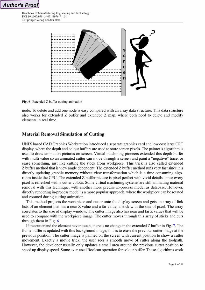
With a great deal of research efforts in the last two decades, the B-rep geometry model has beenimproved significantly in terms of Boolean operation stability, but the B-rep based IPMs are stilllimited to 2.5-axis milling (Fig. 11). Park reported a prismatic IPM generation method that employeda polygon extrusion algorithm to sweep a ball-nose cutter (Park et al. 2003).
Host CAD Section In-process ModelSince the integrated B-rep IPMs cannot be created inside a CAD geometry model, a new, ad-hoccross-section-wire-frame based approach was proposed in a forging die CAD/CAM system (Liuet al. 1991). The aim was to use a series of paralleled cross-section drawings to represent 3D shapes.Figure 12 depicts the cross section representation of a link rod 3D shape.
The cross section IPM is widely used in many commercial CAD/CAM systems. I-DEAS fromSDRC uses water level cross-section as an IPM for generative machining. In a traditional NCprogramming environment, a significant amount of time is spent trying to visualize the in-processstock as it goes through various process stages.With I-DEAS, the wireframe section in-process stockmodel can be created for downstream applications such as toolpath generation, process planning,fixture designing and clamp positioning.
A part can be sectioned along the Z, X and Y axis that is shown in Fig. 13. The Z-axis section isusually called water level section. For 3-axis milling, the water level section could have many loops,causing complications in the set operation between sections. X and Y sections are single half loopsand the Z value is unique for every point, thus simplifying the set operation considerably.
Handbook of Manufacturing Engineering and TechnologyDOI 10.1007/978-1-4471-4976-7_16-1# Springer-Verlag London 2014
Page 12 of 54
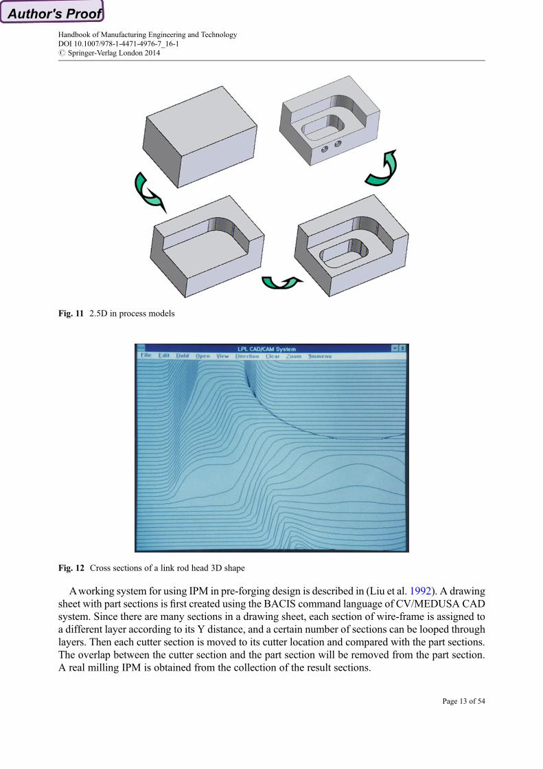
Aworking system for using IPM in pre-forging design is described in (Liu et al. 1992). A drawingsheet with part sections is first created using the BACIS command language of CV/MEDUSA CADsystem. Since there are many sections in a drawing sheet, each section of wire-frame is assigned toa different layer according to its Y distance, and a certain number of sections can be looped throughlayers. Then each cutter section is moved to its cutter location and compared with the part sections.The overlap between the cutter section and the part section will be removed from the part section.A real milling IPM is obtained from the collection of the result sections.
Fig. 12 Cross sections of a link rod head 3D shape
Fig. 11 2.5D in process models
Handbook of Manufacturing Engineering and TechnologyDOI 10.1007/978-1-4471-4976-7_16-1# Springer-Verlag London 2014
Page 13 of 54

The display of sections is provided by line segments and can be confusing when there are toomany lines, i.e. there is a need to render the IPM as a realistic 3D image. In order to calculate thesurface normal required for rendering, the section wire frame is divided along the X direction by thesame step as that for Y direction. A so-called regulated section is formed to facilitate the calculationof surface normal and interpolation of points between the sections. A given node in one section islinked to a node in the next section. A node’s normal can be calculated from the four neighbouringnodes. Figure 14 shows the regulated section representation, which in fact is called Z map.
Fig. 13 Section representation
Fig. 14 Regulated section representation
Handbook of Manufacturing Engineering and TechnologyDOI 10.1007/978-1-4471-4976-7_16-1# Springer-Verlag London 2014
Page 14 of 54

Z Map Based In-process Geometrical Model
The regulated section can also be used to accelerate set operation between cutter section and partsection. Calculation of intersections and trimming between two sections are time consuming and there-ordering of the line segments requires more computing time. This can be improved with theregulated sections, where the line segments are indexed by both cutter section and part section. Onlythe line segments with the same index are compared and trimmed, there is no need to trim two linesegments. If all the line segments fall on the regulated nodes, there is no need to trim two linesegments. The set operation can be simplified to the comparison of two Z values, which is very fastand stable. Hence, the Z map representation of IPM emerges (Jerard et al. 1989).
Classic Z MapIf all the section line segments fall on the nodes, the object surface can be represented by the Z valuesof the nodes. A map of Z values represents the object geometry. In computer language terms, theZ map can be expressed as a two-dimension array Z[i, j], where i represents the index in X directionand j represents the index in Y direction. The XY position of the Z map can be calculated by i orj times grid size.
The best analogy for a Zmap is a needle bed, where needles are uniformly distributed over the XYplane of Fig. 15. The tip of every needle touches the object surface that it represents. A millingsimulation can be seen as the tool cutting through the needle bed. These needles can be described inmathematical terms as Z-axis aligned vectors, passing through grid points on the XYplane. A Zmaprepresentation can be used effectively for surfaces that are visible looking “downwards” on the XYplane. Since 3-axis milling parts are composed of surfaces visible from the Z direction, they can beexpressed effectively by the Z map representation. With a Z map representation, the machiningprocess can be simulated by cutting the Z map vectors with the cutter.
Figure 16 shows an example of a 3-axis milling simulation system that was developed by the firstauthor in 1990. The system used DOS extender for Z map and SVGA for Z map rendering. The GUIand NC toolpath wireframe display was coded with high C graphics library. The GUI and mousecontrol developments were a very hard job and this was not resolved until the arrival of Windows95 and OpenGL.
The vectors in a Z map have direction and length and are infinitely thin without volume. The topof each vector, where the Z map and object meet, is just a point having no shape. Only at this pointthe Z map and the object meet with each other. Z map models cannot provide accurate objectgeometry outside these points. There are many ways of interpolating the geometry between grid
Fig. 15 Needle bed sample of classic Z map model
Handbook of Manufacturing Engineering and TechnologyDOI 10.1007/978-1-4471-4976-7_16-1# Springer-Verlag London 2014
Page 15 of 54

points in order to render a Z map model, for example, forming a triangle from three neighbouringZ values.
It is obvious that the XY resolution of the Z map grid determines the precision of a Z map model.A finer grid has greater precision but requires increased memory. For a part of 1 m * 1 m, the size ofthe Z map is 1,000 � 1,000 if the precision is 1 mm, but it increases to 2,000 � 2,000 if theprecision is 0.5 mm. Reducing the model size and achieving suitable precision becomes a criticalissue in a Z map.
One of the solutions is to balance Z precision and XYprecision. An integer array is used to replacethe more common floating array of a Z map, which reduces the Z map size by half. At the same time,this improves the Boolean operation speed because the comparison of integers is much faster thanthe comparison of floats. The memory requirement of a Z map is halved again by compressing theZ map file section by section, similar to image compression.
Because of the simplicity of its data structure and fast computation time, the Z map model is usedby most commercial CAM software (Jerard et al. 1989; Stifter 1995; Maenga et al. 2003). However,a Z map cannot approximate vertical wall very well since it always has a slope as shown in Fig. 17.This is not a problem for forging die design since there are always draft angles in forging parts, but itis a serious problem for milling parts since profiling nearly always creates vertical walls.
Extended Z MapSince the precision of the Z map is determined mainly by XY resolution along the vertical walls,increasing the resolution along these walls while reducing memory is a key issue. Fortuitously, oneimportant feature of 3-axis milling can be leveraged. Viewing from the top, the vertical walls onlycover a small percentage of the Z direction projection, so it should be possible to use finer resolutionalong the vertical walls while maintaining a rough resolution in the planar area. This was the initialidea for an extended Z map; at least one grid on a Z map is segregated into sub-cells. Only gridscorresponding to intricate features on the surface of an object are assigned sub-cells to improve therepresentation of object features. Figure 18a illustrates the plan view of the Zmap grid with sub-cells52 the front sectional view, while Fig. 18b shows the sectional view.
Fig. 16 Z map milling simulation
Handbook of Manufacturing Engineering and TechnologyDOI 10.1007/978-1-4471-4976-7_16-1# Springer-Verlag London 2014
Page 16 of 54
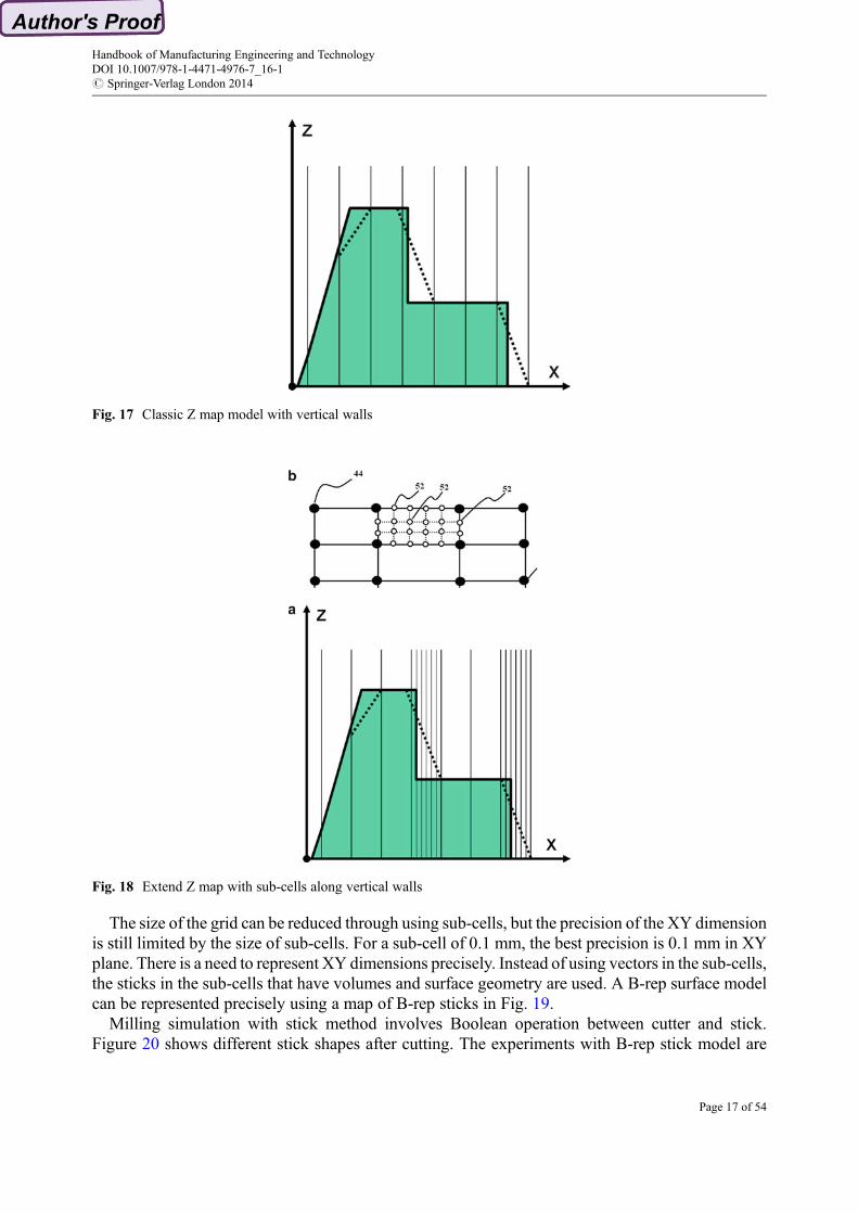
The size of the grid can be reduced through using sub-cells, but the precision of the XY dimensionis still limited by the size of sub-cells. For a sub-cell of 0.1 mm, the best precision is 0.1 mm in XYplane. There is a need to represent XY dimensions precisely. Instead of using vectors in the sub-cells,the sticks in the sub-cells that have volumes and surface geometry are used. A B-rep surface modelcan be represented precisely using a map of B-rep sticks in Fig. 19.
Milling simulation with stick method involves Boolean operation between cutter and stick.Figure 20 shows different stick shapes after cutting. The experiments with B-rep stick model are
Fig. 17 Classic Z map model with vertical walls
Fig. 18 Extend Z map with sub-cells along vertical walls
Handbook of Manufacturing Engineering and TechnologyDOI 10.1007/978-1-4471-4976-7_16-1# Springer-Verlag London 2014
Page 17 of 54

very slow and a huge B-rep model is created. To simplify stick and Boolean operation, a polygon isused instead of real surface in a stick cell. The data structure of a polygon is much simpler than that ofa B-rep which needs a group of complicated pointers to maintain a double wing data structure.
The real world objects are not always uniform in the XY plane and can be any shape. Nodes areused to enhance sub-cell precision in object face representations. For example, one edge of thesub-cell may have two overlapping nodes to represent a vertical face. The nodes of a sub-cell maynot be uniformly distributed over XYplane. Figure 21 depicts an exploded plan view of a portion ofthe Z map grid with nodes 54 and illustrates how stick method represents a circular hole and verticalwalls.
Z map has height value that is only suitable for 3-axis machining, where everything can be viewedfrom the top. Machine components usually need six sides machining, either with a rotate table or 5-axis control, which may result in hollow portions in some areas, which cannot be seen from the top.If one ray is tracing through the hollowed object, there may be more than two intersections. Insteadof one height value, Z map could be extended to multiple values as in Fig. 22. Extended Z buffer isa special multiple value Z map aligning with screen orientation.
Fig. 19 Stick method
Fig. 20 Different shapes of stick elements after cutting
Handbook of Manufacturing Engineering and TechnologyDOI 10.1007/978-1-4471-4976-7_16-1# Springer-Verlag London 2014
Page 18 of 54

Figure 23 shows shop floor examples of extended Z map IPM based NC simulation andverification that was developed in Singapore Institute of Manufacturing Technology (Liu 2005)and implemented in precision engineering industry for a decade. The detailed description of theextended Z map IPM can be found in two patents (Liu et al. 2002).
Voxel Based In-process Geometrical Model
Over the last three decades academic research explored many variations of deformable volumetricmodel, such as discrete vector, graft tree, octree or hierarchical space decomposition and ray tracingmethod. These inspiring research works contributed to the main stream volumetric in-process modelstudy, which starts with extended Z buffer material removal animation, enriched with Z map stick,and ends with extended voxel model. The virtual machining industry learn, enhance, and merge
Fig. 21 Sticks to approximate vertical wall
Fig. 22 Extended Z map to multiple values
Handbook of Manufacturing Engineering and TechnologyDOI 10.1007/978-1-4471-4976-7_16-1# Springer-Verlag London 2014
Page 19 of 54

these techniques into their hybrid in-process models, which may use extended Z buffer for materialremoval animation, stick for 3 axis mill, voxel for 3–5 axis mill or turn-mill and swept volume foroptimization. However, virtual machining industries seldom publish their internal data structuresand algorithms except for a few patents, only disclosing certain techniques that could be easilyidentified by the export data and user interface.
Octree Hierarchical Space DecompositionInstead of representing the blank as a collection of sticks in 3 axis NC simulation, it is possible torepresent it as a collection of cubes or spheres or any such cell of the same size. This is called uniformspace decomposition (USD). However, this is a very expensive way of representing solids so it islimited to medical imaging application. Assuming that a bit is required to denote a cell, forrepresenting a workpiece of size 1 m with a resolution of 1 mm, more than1,000 � 1,000 � 1,000 GB is required. Obviously this is not practicable. Therefore, methods torepresent an object as a collection of cells of varying sizes were developed, such as hierarchicalspace decomposition (HSD) or octree representations in Fig. 24.
An octree is a tree data structure in which each internal node has exactly eight children. Octree isa HSD representation in which an object is represented by a set of bigger cubes with subdivisions ofeight smaller cubes. This reduces the memory requirement considerably. Each cube is one-eighth ofits parent cube in size and is called an octant. All the octants can be visualized as the nodes of a tree inwhich every node has eight branches. An octant can be completely inside or outside the solid, whenthere is no need to further divide they become leaf nodes. Only boundary octants are furthersubdivided into eight octants. This subdivision continues till the size of the sub octant equals therequired resolution. The total number of octants to be stored in an octree is much less than that ofUSD representation, because the boundary octants take part in the subdivision. In practice, thenon-boundary octants memory can be reduced with a compression algorithm. It was found that in thecase of an octree the number of octants needed is nearly proportional to the surface area of the object.
Fig. 23 Extended Z map based milling simulation
Handbook of Manufacturing Engineering and TechnologyDOI 10.1007/978-1-4471-4976-7_16-1# Springer-Verlag London 2014
Page 20 of 54

All octree computations are based on integer arithmetic, which means that the analysis algorithmsare fast. Octree algorithms are readily parallel-processes by definition. Memory required by octreerepresentation is independent of the number of primitives and operations. For a given resolution,memory required depends only on the surface area of the object. Boolean operations and renderingdisplay in isometric view are trivially simple since these operations require only tree traversal withsimple exchange of terms. The user is free to choose any desired accuracy (at the cost of speed andmemory). Coarse modelling is a facility unique to HSD. A coarse model of a solid can be producedand processed quickly to get an order of magnitude estimate of the results. If these are foundfavourable, a more accurate refined model can be produced.
However, Octree is an approximate representation and memory requirement increases exponen-tially with increase in resolution. Instead of using subdivisions of the boundary octants, manyresearchers proposed new ways to precisely describe the boundary surface geometry. The boundaryoctant is renamed cell since there is no sub octant anymore.
Graft tree added two extra nodes on each edge so a few triangles could be formed to approximateany polygon mesh. If a mesh node falls inside this cell, an extra node will be recorded. A surface issubdivided by cells into small pieces and recorded into the cell.
One inspiring invention is the so called machining history based method. Instead of recordingsurface into octant, this method records the neighbouring CNC toolpath and the linked cutter into thecell. The neighbouring toolpath is the piece of toolpath that most likely will cut into the cell. Anyzoom or rotate of the workpiece will trigger a re-calculation of cell geometry and generate a moredetailed extended Z buffer image on screen. This is good for small NC programs. However, thehistory of machining grows with the NC code, which could be millions of lines of text.
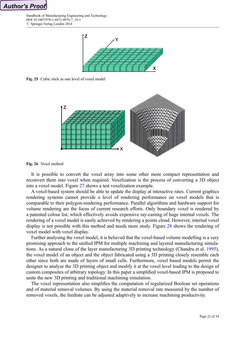
Voxel as Multiple Layers of Cubic StickThe term voxel represents a volume element in space decomposition geometrical model schema, justlike the term pixel denotes a picture element in raster graphics. Extended Z map with stick methodcould be considered as a simplified and extended one layer voxel model as in Fig. 25.
Figure 26 depicts an example of the voxel model, which could be considered as a many unit heightstick element stacking together and the memory requirements are enormous. There is a need to storethe voxel array in compressed form and use algorithms that will operate directly on the compresseddata, especially when the material is homogenous, where internal voxel could be represented byboundary voxel extension.
Fig. 24 Octree hierarchical space decomposition
Handbook of Manufacturing Engineering and TechnologyDOI 10.1007/978-1-4471-4976-7_16-1# Springer-Verlag London 2014
Page 21 of 54
It is possible to convert the voxel array into some other more compact representation andreconvert them into voxel when required. Voxelization is the process of converting a 3D objectinto a voxel model. Figure 27 shows a test voxelization example.
A voxel-based system should be able to update the display at interactive rates. Current graphicsrendering systems cannot provide a level of rendering performance on voxel models that iscomparable to their polygon-rendering performance. Parallel algorithms and hardware support forvolume rendering are the focus of current research efforts. Only boundary voxel is rendered bya patented colour list, which effectively avoids expensive ray-casting of huge internal voxels. Therendering of a voxel model is easily achieved by rendering a points cloud. However, internal voxeldisplay is not possible with this method and needs more study. Figure 28 shows the rendering ofvoxel model with voxel display.
Further analysing the voxel model, it is believed that the voxel-based volume modelling is a verypromising approach to the unified IPM for multiple machining and layered manufacturing simula-tions. As a natural clone of the layer manufacturing 3D printing technology (Chandru et al. 1995),the voxel model of an object and the object fabricated using a 3D printing closely resemble eachother since both are made of layers of small cells. Furthermore, voxel based models permit thedesigner to analyse the 3D printing object and modify it at the voxel level leading to the design ofcustom composites of arbitrary topology. In this paper a simplified voxel-based IPM is proposed tounite the new 3D printing and traditional machining simulation.
The voxel representation also simplifies the computation of regularized Boolean set operationsand of material removal volumes. By using the material removal rate measured by the number ofremoved voxels, the feedrate can be adjusted adaptively to increase machining productivity.
Fig. 25 Cubic stick as one level of voxel model
Fig. 26 Voxel method
Handbook of Manufacturing Engineering and TechnologyDOI 10.1007/978-1-4471-4976-7_16-1# Springer-Verlag London 2014
Page 22 of 54

Unified In-process Model of Multi Machining and 3D PrintingDuring the novel combined 3D printing and multi machining, such as shape deposition manufactur-ing, a 3D printing part needs to be inserted with an electronic device and milled to a certain shape.The unified 3D printing-machining simulation displays the machining process in which the initial3D printing generated workpiece is incrementally converted into the finished part. The voxel
Fig. 27 Experiment voxelization
Fig. 28 Rendering model with voxel display
Handbook of Manufacturing Engineering and TechnologyDOI 10.1007/978-1-4471-4976-7_16-1# Springer-Verlag London 2014
Page 23 of 54

representation is used to model efficiently the state of the IPM, which is generated by successivelysubtracting tool swept volumes from the workpiece (Donggo et al. 2000).
Figure 29 illustrates the framework of the unified voxel-based IPM for 3D printing and multimachining. The voxel based 3D printing simulation can be achieved by the voxelization of the roadshapes, which are similar to a pipe along the 3D printing toolpath. Boolean addition between theroad shape voxel and the base voxel is fast and stable, independent of the model shape, which isa critical issue with B-rep. One layer of road shapes would make a B-rep based solid modeller veryslow, since B-rep Boolean operation is dependent on model shape.
Furthermore, proposed unified IPM is a natural voxel mesh model (Nakashima et al. 2002) for socalled image based CAE analysis and this further unified CAD, CAM and CAE.
Current 3D CAD involves only shape data, which consequently poses certain difficulties inprocess modelling and simulations aimed at predicting the performance of final products. Kaseintroduced voxel CAD, which stores physical attributes together with 3D shape data (Kaseet al. 2003). Voxel CAD allows the sharing of data by different simulations and flexible manufactur-ing methods.
There are other approaches [17Q2 –19] on unified model of manufacturing processes but none ofthem could achieve the uniformity that voxel model could offer. Voxel model could be used in NCtoolpath generation-simulation-optimization, shape design optimization, forming process simula-tion, and many other manufacturing applications. This will result in a unified volumetric geometrymodel for all design and manufacturing processes that would erase the data exchange barrier andCAE re-meshing problem.
CGTech started from NC verification software and then to NC optimization and simulationsoftware. During the first 15 years, CGTech has concentrated on removing material, and recentlyit started working on adding material. Since most aircrafts now need carbon fibre, the Boeing787 program asked CGTech to develop the manufacturing and simulation software of composite. So
Fig. 29 Framework of unified IPM for multi machining and 3D printing
Handbook of Manufacturing Engineering and TechnologyDOI 10.1007/978-1-4471-4976-7_16-1# Springer-Verlag London 2014
Page 24 of 54

now after 10 years, composite manufacturing and simulation is one of its core businesses. For thefibre composite, VERICUT can not only simulate, but also can do the fibre placement program.Therefore, composite manufacturing and simulation has become a new growth for virtualmachining.
VERICUTcomposite simulation (Fig. 30) reads CADmodels and NC programs, either fromVCPor other composite layup path-generation applications, and simulates the sequence of NC programson a virtual machine. Material is applied to the layup form via NC program instructions in a virtualCNC simulation environment. The simulated material applied to the form can be measured andinspected to ensure the NC program follows manufacturing standards and requirements. A reportshowing simulation results and statistical information can be automatically created.
AVirtual Machining System Example
Practice is the best way to learn. QuickCNC from Singapore Institute of Manufacturing Technologyis taken as an example to demonstrate the functionality of virtual machining and its process flow. Thesystem has been successfully applied in industry and training schools for many years to promotevirtual machining technology.
Virtual Machining Process FlowThe graphic user interface (GUI) of QuickCNC is depicted in Fig. 31. The multiple windows can beviewed from different angles, zoom factors and detail levels. For example, total toolpath and currenttoolpath can be separately displayed without workpiece or against design part, with cutter or holder.The view details are easily controlled with NC toolpath toolbar buttons and hot keys.
The right dialog bar controls toolpath and simulation. The top slide bar interactively controlssimulation speed in run time, the user can slow down cutting animation to watch a certain operationor get a result without animation. The cutter can move along the toolpath with NC toolpath dialog
Fig. 30 VERICUT composite simulation
Handbook of Manufacturing Engineering and TechnologyDOI 10.1007/978-1-4471-4976-7_16-1# Springer-Verlag London 2014
Page 25 of 54
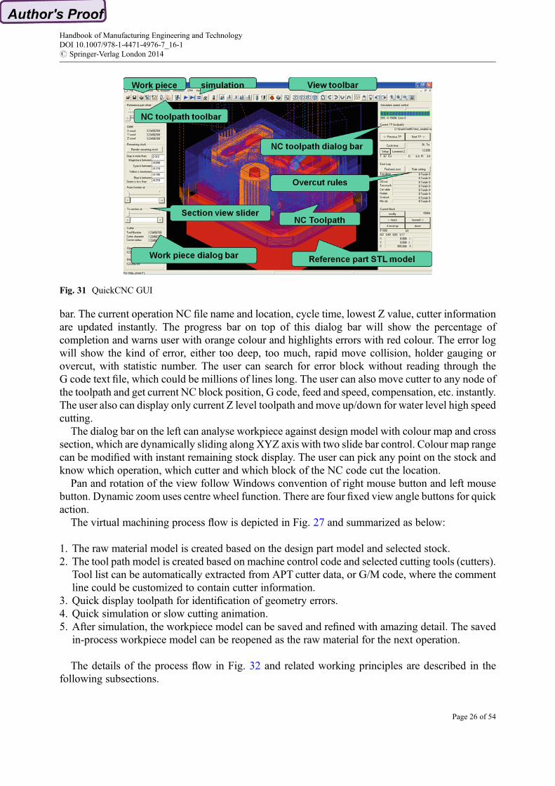
bar. The current operation NC file name and location, cycle time, lowest Z value, cutter informationare updated instantly. The progress bar on top of this dialog bar will show the percentage ofcompletion and warns user with orange colour and highlights errors with red colour. The error logwill show the kind of error, either too deep, too much, rapid move collision, holder gauging orovercut, with statistic number. The user can search for error block without reading through theG code text file, which could be millions of lines long. The user can also move cutter to any node ofthe toolpath and get current NC block position, G code, feed and speed, compensation, etc. instantly.The user also can display only current Z level toolpath and move up/down for water level high speedcutting.
The dialog bar on the left can analyse workpiece against design model with colour map and crosssection, which are dynamically sliding along XYZ axis with two slide bar control. Colour map rangecan be modified with instant remaining stock display. The user can pick any point on the stock andknow which operation, which cutter and which block of the NC code cut the location.
Pan and rotation of the view follow Windows convention of right mouse button and left mousebutton. Dynamic zoom uses centre wheel function. There are four fixed view angle buttons for quickaction.
The virtual machining process flow is depicted in Fig. 27 and summarized as below:
1. The raw material model is created based on the design part model and selected stock.2. The tool path model is created based on machine control code and selected cutting tools (cutters).
Tool list can be automatically extracted from APT cutter data, or G/M code, where the commentline could be customized to contain cutter information.
3. Quick display toolpath for identification of geometry errors.4. Quick simulation or slow cutting animation.5. After simulation, the workpiece model can be saved and refined with amazing detail. The saved
in-process workpiece model can be reopened as the raw material for the next operation.
The details of the process flow in Fig. 32 and related working principles are described in thefollowing subsections.
Fig. 31 QuickCNC GUI
Handbook of Manufacturing Engineering and TechnologyDOI 10.1007/978-1-4471-4976-7_16-1# Springer-Verlag London 2014
Page 26 of 54

Automatic Creating Raw Material ModelA rawmaterial model can be interactively defined as a box or cylinder as in Fig. 33 or generated fromcasting or forging model as in Fig. 34 or design a part model as in Fig. 35.
In Fig. 33, the origin of work coordinate system (WCS) has to be selected, usually at the top centreor corner, since it is easy to measure with a touch probe. A model resolution - the size of voxel cell,has to be specified as well. The system usually gives a default value in line with the size of the part,mostly between 1 mm and 0.1 mm. However, this is not the simulation precision, which is usuallyless than 1 mm.
Machining a part from a block could be a great waste if the part and the raw material differ a lot,sometimes half of the raw material has to be machined and becomes waste. In order to reduce wasteand achieve faster production with near net shape machining, the raw material could be forged orcast into the final part shape with a few millimetres of machining allowance.
The forging and casting parts, designed with conventional CAD tools, can be exported to thevirtual machining system through a stereo lithography (STL) file which is a triangle polygonmesh intext or binary format.
As shown in Fig. 34, a rawmaterial model is generated from a casting or forging model, where thegeometry may be a complex surface. The origin of work coordinate system (WCS) usually followsthe part origin.
The so called design part is the target geometry of machining, where the raw material stock modelis the original shape of workpiece. The box envelop of design part can be automatically extracted togenerate a raw material block for quick CNC simulation. However even in shop floor practice it isdifficult to get an exact block of the design part.
Automatic Load NC File and Reverse Post into ToolpathMachine control data (MCD), such as G/M code, are reverse posted into internal NC toolpath,usually in APT CL data format. The APT CL data file of commercial CAM system can be directlyread in without the reverse processing step. The grammar errors, such as missing key words, could
Fig. 32 Virtual machining process flow
Handbook of Manufacturing Engineering and TechnologyDOI 10.1007/978-1-4471-4976-7_16-1# Springer-Verlag London 2014
Page 27 of 54

be discovered at this stage. Some geometrical errors, such as centre of the circle not-aligned or twoblocks overlapping could be highlighted with colours in toolpath display.
The APTCL data file contains cutter definition, such as cutter diameter/radius/length/angle, so thecutter information will be automatically loaded without human selection. However, there is noofficial cutter definition in G/M NC file, manual cutter selection is a boring task and introducesanother possible human error in NC verification. QuickCNC automated the cutter selection by threesteps:
1. QuickCNC builds a cutter table with company specified cutter names.2. Customize commercial CAM system to export cutter definition on top of NC file inside comment
lines: (HTC50R4.5 process R).3. QuickCNC parse comment lines to search for cutter definition.
Awell defined cutter table can standardize the tool room operation and management. Holders andspecial cutters can be defined as well. Figures 36 and 37, respectively, illustrate the cutter definitionand tool list, while Fig. 38 depicts automatic cutter search using cutter name. A new cutter will becreated in the cutter table if there is no cutter match.
Fig. 33 Define a raw material stock
Handbook of Manufacturing Engineering and TechnologyDOI 10.1007/978-1-4471-4976-7_16-1# Springer-Verlag London 2014
Page 28 of 54

The subprogram can be automatically loaded from the main program in Fig. 39. QuickCNC willlook into the subprogram files and find the linked program number at the head of the file.
Three steps for fully automatic simulation are to automatically create rawmaterial, open all files inthe same folder, search for cutter and subprogram. Now a machinist can complete a quick simulationwith just three mouse clicks to load STL part file to create raw stock, reverse post processing a wholefolder of G code files into toolpath and quick simulates machining operation and automatic verifyNC program.
Fig. 35 Create a block stock from design part model
Fig. 34 Create raw material stock from casting or forging part model
Handbook of Manufacturing Engineering and TechnologyDOI 10.1007/978-1-4471-4976-7_16-1# Springer-Verlag London 2014
Page 29 of 54

Quick Toolpath DisplayWorkpiece, cutter and toolpath can be interactively viewed with zoom and rotate. The cutter movesalong toolpath with a current position in the current operation that is highlighted as the currenttoolpath in red. Figure 40 displays all toolpaths in one viewport, which could be overlapping andconfusing. A part could be machined with multiple operations, such as drilling, roughing, semifinishing and finishing milling, which are in a planed order of different NC toolpath. A colourscheme is used to distinguish NC toolpath with different colours and highlight the current operationwith red.
Figure 41 displays only current toolpath clearly against part model. For current toolpath, everynode is highlighted with a white dot. The cutter and holder could be shown with solid colour orwireframe, even with a line or white dot, so the toolpath would not be blocked by cutter shadow.
Figure 42 highlights NC program errors, such as too deep cut, full width cut, cutter fast move intomaterial, too much cut, cut into machine table, holder gauging, overcut and overlapping blocks.
Fig. 36 Cutter definition
Fig. 37 Tool list dialog box
Handbook of Manufacturing Engineering and TechnologyDOI 10.1007/978-1-4471-4976-7_16-1# Springer-Verlag London 2014
Page 30 of 54

In the real world, CNC machine tool follows MCD control step by step. In virtual machining, it ispossible to move forward and backward for easy check up. Figure 43 shows the toolpath controlbuttons that can be used to move cutter forward or backward along the toolpath, where the currentNC block information is updated immediately, so the user can check and verify interactively.
Fig. 38 Automatic search for cutter
Fig. 39 Automatic search for sub program
Handbook of Manufacturing Engineering and TechnologyDOI 10.1007/978-1-4471-4976-7_16-1# Springer-Verlag London 2014
Page 31 of 54

Cutting SimulationQuick simulation or slow cutting animation can start and switch at ease, as shown in Fig. 44. Theanimation speed could be interactively adjusted with a slide bar that is on the top right of the dialogbar. The workpiece can be rotated and zoomed at any moment of simulation.
Upon the completion of the simulation, the initial raw material is machined into final shape, anin-process model is shown in Fig. 45, and a log file is automatically generated. The file records filename, cutter number and name, diameter and radius, length, minimum length and all types of error.
• C:\QuickCNC\training_example.nc• Cuttter Number ¼ 67• Cutter name ¼ D12
Fig. 40 Display all toolpath
Fig. 41 Highlight toolpath
Handbook of Manufacturing Engineering and TechnologyDOI 10.1007/978-1-4471-4976-7_16-1# Springer-Verlag London 2014
Page 32 of 54

• Cutter diameter ¼ 12.000• Corner radius ¼ 0.000• Error Type 1 Too deep cut ¼ 0• Error Type 2 Full width cut ¼ 0• Error Type 3 Rapid G0 cut ¼ 0• Error Type 4 Too much cut ¼ 0• Error Type 5 Plunge into table ¼ 0• Error Type 6 Holder Gouging ¼ 0• Error Type 7 Overcut part face ¼ 0• Error Type 8 Minimum distance ¼ 0• Cutter length ¼ 100.000 mm
Fig. 42 Toolpath error display
Fig. 43 Quick move cutter forward and backward
Handbook of Manufacturing Engineering and TechnologyDOI 10.1007/978-1-4471-4976-7_16-1# Springer-Verlag London 2014
Page 33 of 54

• Cutter length can be reduced ¼ 12• Cutter length should be longer than ¼ 88.000• Volume of the remaining stock ¼ 71,267
After simulation, the workpiece in-process model can be saved and retrieved later for the next stepof operation.
Fig. 44 Start simulation
Fig. 45 Completed simulation
Handbook of Manufacturing Engineering and TechnologyDOI 10.1007/978-1-4471-4976-7_16-1# Springer-Verlag London 2014
Page 34 of 54

Refined Workpiece In-process Model DisplayThe workpiece in-process model is displayed in a rough mode for quick interactive viewing, such aszoom and rotates with easy mouse control. Figure 46 shows the refined workpiece display withamazing detail, such as the remaining stock and scallop height, with a colour map that could becustomized by user.
The mouse cross can be used as a probe to measure XYZ position on workpiece surface. Thecutter name and operation for this position can be displayed instantly on the workpiece dialog bar, asshown in Fig. 47.
Fig. 46 Zoom to refined details
Fig. 47 Measure workpiece in-process model against part design
Handbook of Manufacturing Engineering and TechnologyDOI 10.1007/978-1-4471-4976-7_16-1# Springer-Verlag London 2014
Page 35 of 54

Cross sections of workpiece could be viewed with or without the design part model. The sectionposition could be controlled with a slide bar for dynamic effects. Figure 48 sectioned the workpiecein-process model along X axis against design model, with the display control dialog box.
QuickCNC can display CNC errors in graphics as shown in Fig. 49, where conventional log filecould be lengthy and difficult to read. Search for error is easy and quick with two buttons.
Figure 50 uses colour map of the remaining stock to visualize the left over from previousmachining operations. User can define the range of interested area. This technique can also beused to show spark gaps in EDM machining.
Fig. 48 Section view against STL model
Fig. 49 Highlight cutting errors
Handbook of Manufacturing Engineering and TechnologyDOI 10.1007/978-1-4471-4976-7_16-1# Springer-Verlag London 2014
Page 36 of 54

Virtual Training of Machinist and CNC Programmer
As a cutting edge technology of modern manufacturing industry, CNCmachining produces essentialinputs for virtually all types of manufacturing products for different applications, including injectionmold, sheet metal die, casting die, jigs and fixtures and other special tools. CNC technology has beenwidely used in computer-aided manufacturing (CAM), high speed machining (HSM) and ultraprecision machining (UPM). The extensive use of CNC significantly improves the productivity ofprecision engineering but has caused a shortage of skilled technicians or machinists, especially in theknowledge intensive areas such as HSM and UPM. Training of skilled machinists is thereforea crucial yet challenging job. A qualified HSM machinist should have good knowledge of machin-ing, understand the operation of the machine tools, and be able to do planning for machining process.Traditionally, trainees acquire their operating skills in several years through observation andreference to the operation manual. After which, they would learn to operate machines for themselvesunder the guidance of experienced operators. The acquisition and maintenance of real CNCmachines, the consumptions of real materials in machining, and the set-up and maintenance forworkshops, all contribute substantially to the high cost of conventional CNC training. Cost-effectiveand safe CNC training is thus highly desired.
An apprentice will get to know a conventional mill by handling it under controlled conditions, bymachining initially simple parts, always being careful to keep the tool far away from the faceplate.Accidents happen. An extra turn of the lever and the tool may hit the machine table. Even a brokencutter and a scratched faceplate in a learning mill is not much of a loss, a CNC machine tool costsseveral times more and is more prone to serious accidents. Awrong line of code may punch the mainspindle towards the machine table, provoking a horrendous collision causing serious losses.Students could be traumatized by the crash and lose interest in this trade, which is facing anincreasing problem of manpower shortage.
With computers becomingmore common, the obvious follow up development is software that cansimulate the entire process, dispensing with the real life machine tool altogether. The challenge ofmoving from a manual machine tool to a CNC version resides at the programming side, not inhandling the machine. Since both PC and CNC control panels use touch screen, it makes little
Fig. 50 Colour map of the remaining stock
Handbook of Manufacturing Engineering and TechnologyDOI 10.1007/978-1-4471-4976-7_16-1# Springer-Verlag London 2014
Page 37 of 54

difference on whether the programming is for a machine simulated in PC or a real life CNCmachinecontrol panel, which itself is a computer, so CNC programming training can be naturally replacedwith virtual machining.While CNC training using real CNCmachines is necessary, the use of virtualreality (VR) technology to support CNC training has been a popular topic in recent years(Avgoustinov 2000).
Simulation of the entire machining processes for CNC training is significant given its lower costand risk-free nature. The drastic decrease of the cost of computer, coupled with the worldwide priceincrease in material and machine tools means that virtual CNC training using computerizedmodelling and simulation is a cost-effective and sustainable approach to technical and professionaleducation in manufacturing applications. The virtual CNC training system is developed for simu-lation of multiple machining processes. It is particularly important in the training of knowledge-intensive high speed and ultra precision machining. Compared with conventional on-site manualtraining or e-learning, the virtual CNC training system greatly increases learning efficiency andeffectiveness of trainees, and improves cost saving in terms of machine and material uses.
Virtual manufacturing is the use of a desktop virtual reality system for the computer-aided designof components and manufacturing processes. Virtual reality is a computer technology that enablesusers to view or ‘immerse’ themselves in an alternate world. Immersion and man–machine interac-tion is the core of VR technology. VR technology has obvious applications in education and trainingwhere potentially dangerous tasks such as flying or surgery are carried out and also has been used formany different applications in a variety of industries. This work provided some insight intoreconstructing of virtual machining centre by using PC platform and realized the machining centrenavigation andman–machine interactive operation. In this virtual environment, users can operate themachining centre and complete a product machining process. Through this virtual platform, userscan obtain knowledge about the structure of machining centre and get familiar with the complexoperation of machining centre before they have the opportunity of manipulating the real machiningtool, which is desirable for practical operation.
Current Status of Virtual CNC TrainingCompared to NC simulation applications which are expensive and mature, the virtual CNC trainingsystem is still primitive. The NC simulator developers are not actively trying to provide a trainingsystem because the training software market is logically smaller than production software. Moreimportantly, NC simulator developers need to revamp the graphics engine or geometry kernel to suiteducation game use. None of the leading NC simulators has any CNC training capability. This leavesthe development of virtual CNC training system to machine tool vendors and schools who do nothave expertise to develop a good graphics engine (Garcia-Plaza et al. 2011).
The CNC control vendors developed their own training system. For example, Siemens developedSinuTrain, which is CNC training software. It runs on PC and is suitable for training purposes andself-study as it is for writing programs and simulation. It serves for writing and simulating NCprograms on a PC, based on the DIN 66025 programming language as well as the productsShopMill, ShopTurn and ManualTurn + and language commands for SINUMERIK® 810D,840D and 840Di controls, all are Siemens products. Programs written with this software can beused on real machines. A prerequisite is that the SinuTrain software is adapted to the SINUMERIKcontrol on which the program is to be executed. This adaptation must be carried out by speciallyqualified personnel, e.g. from Siemens. It is important to stick to Siemens and the machine-toolmanufacturer’s instructions when adapting the software. No liability is accepted by Siemens if theserequirements are not adhered.
Handbook of Manufacturing Engineering and TechnologyDOI 10.1007/978-1-4471-4976-7_16-1# Springer-Verlag London 2014
Page 38 of 54
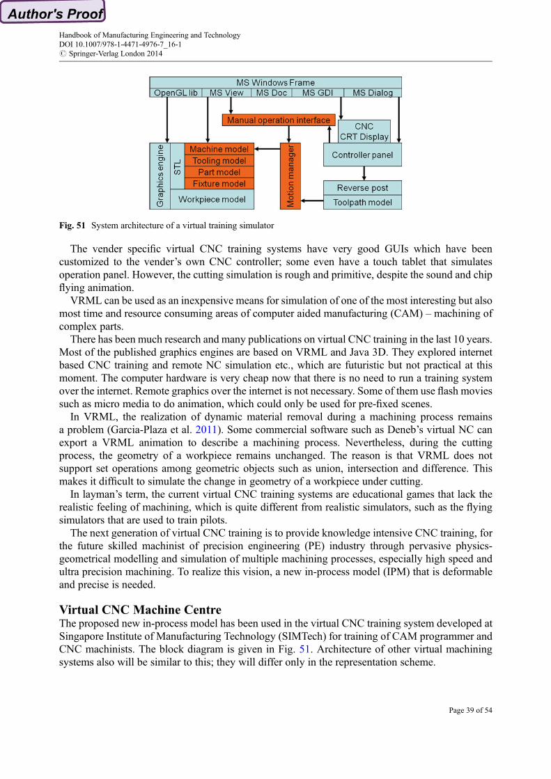
The vender specific virtual CNC training systems have very good GUIs which have beencustomized to the vender’s own CNC controller; some even have a touch tablet that simulatesoperation panel. However, the cutting simulation is rough and primitive, despite the sound and chipflying animation.
VRML can be used as an inexpensive means for simulation of one of the most interesting but alsomost time and resource consuming areas of computer aided manufacturing (CAM) – machining ofcomplex parts.
There has been much research and many publications on virtual CNC training in the last 10 years.Most of the published graphics engines are based on VRML and Java 3D. They explored internetbased CNC training and remote NC simulation etc., which are futuristic but not practical at thismoment. The computer hardware is very cheap now that there is no need to run a training systemover the internet. Remote graphics over the internet is not necessary. Some of them use flash moviessuch as micro media to do animation, which could only be used for pre-fixed scenes.
In VRML, the realization of dynamic material removal during a machining process remainsa problem (Garcia-Plaza et al. 2011). Some commercial software such as Deneb’s virtual NC canexport a VRML animation to describe a machining process. Nevertheless, during the cuttingprocess, the geometry of a workpiece remains unchanged. The reason is that VRML does notsupport set operations among geometric objects such as union, intersection and difference. Thismakes it difficult to simulate the change in geometry of a workpiece under cutting.
In layman’s term, the current virtual CNC training systems are educational games that lack therealistic feeling of machining, which is quite different from realistic simulators, such as the flyingsimulators that are used to train pilots.
The next generation of virtual CNC training is to provide knowledge intensive CNC training, forthe future skilled machinist of precision engineering (PE) industry through pervasive physics-geometrical modelling and simulation of multiple machining processes, especially high speed andultra precision machining. To realize this vision, a new in-process model (IPM) that is deformableand precise is needed.
Virtual CNC Machine CentreThe proposed new in-process model has been used in the virtual CNC training system developed atSingapore Institute of Manufacturing Technology (SIMTech) for training of CAM programmer andCNC machinists. The block diagram is given in Fig. 51. Architecture of other virtual machiningsystems also will be similar to this; they will differ only in the representation scheme.
Fig. 51 System architecture of a virtual training simulator
Handbook of Manufacturing Engineering and TechnologyDOI 10.1007/978-1-4471-4976-7_16-1# Springer-Verlag London 2014
Page 39 of 54

Virtual CNC machine and control panel were developed on Microsoft Windows platform, withOpenGL as the graphics engine. The system architecture followsMicrosoft Application Framework,with a modeless dialog box as the blue print for control panel.
The CNC control panel in Fig. 52 is different from normal Microsoft Windows Dialog in terms ofuser experience, since CNC control panels were developed before the PC age, with CRT display andhard buttons. In order to simulate the traditional CNC control panel, conventional modeless dialoghas to be customized with special graphics features, even buttons were drawn from the bitmapimage. How to turn the knobs is another problem, the mouse centre wheel was employed to rotate.
The machine frame, door knob, spindle, workpiece, tool change button, probe indicator and worktable are shown in Fig. 53. All the tools on the machine are operable with mouse buttons and centrewheel.
Fig. 52 Graphics user interface of a virtual training simulator
Fig. 53 Machine frame and fixtures of a virtual training simulator
Handbook of Manufacturing Engineering and TechnologyDOI 10.1007/978-1-4471-4976-7_16-1# Springer-Verlag London 2014
Page 40 of 54

Virtual measurement on machine tool can be realized with virtual vise, dial indicator, probe,wiggler and tool pre-setter in Fig. 54. The virtual instruments reflect the manual operation in thesame way as the real one; the indicator needles rotate just like a real watch; the wiggler vibrates witha shadow. The user can manually turn the instrument with mouse clicks and centre wheel.
With these virtual tooling components, a trainee can learn how to clamp workpiece on themachine table virtually with a predefined operation procedure, as shown in Fig. 55.
The trainees can use the system to simulate the milling process and save the “machined”model forother downstream machining processes. Figure 50 demonstrates the simulation of the remainingstock and the scallop height. In addition, they can control the simulation speed to see the details atany angle on the current situation of the machining, which is difficult if not impossible in the realmachine based training.
A set of different machining samples has been provided to demonstrate how the generated tool-path works with cutter under various cutting parameters with the aid of the virtual controller.Trainees can learn different setups in a short time using virtual simulator on PC, which significantlyshortens the learning curve compared to the traditional training in a workshop.
While it is dangerous to show the effect of a wrong setup or NC code on the shop floor, the virtualsimulator has graphics and sound developed to synthesize various effects. In particular, the virtualCNC training system can simulate an accident using a graphic and sound effect when a trainee
Fig. 54 Virtual vise, dial indicator, probe, wiggler and tool pre-setter
Fig. 55 Virtual CNC simulates the clamping of workpiece
Handbook of Manufacturing Engineering and TechnologyDOI 10.1007/978-1-4471-4976-7_16-1# Springer-Verlag London 2014
Page 41 of 54

breaks a leg of a work-piece during the virtual machining. Among several benefits safety andmaterial cost reduction are the direct and major gains from virtual simulation.
Virtual CNC Control PanelThe virtual CNC control panel is a virtual copy of an actual machine control panel. The virtual CNCpanel is integrated with a simulated machine tool. The simulated machine responds to the programs,commands and inputs of the virtual control panel in the same manner as a real machine. The CNCemulator and machine tool simulator allow anyone to learn actual CNC automation at any time andin any place. The new Windows touch screen serves as a good control panel interface. For modernLCD touch screen control panel, touch screen PC is a natural clone so the emulation is perfect withthe virtual key pad.
The virtual display emulates real CRT display with traditional style of text. The display contentwill change according to different control modes, such as actual position, all positions, WCS table,compensation, etc., as shown in Fig. 56. The virtual CRT display and machine movement issynchronized without delay.
After the trainee measures the workpiece position on machine table, the data can be easily input tothe virtual control panel by virtual key pad. The data can be retrieved in a later session.
Fig. 56 Virtual CNC control panel display
Handbook of Manufacturing Engineering and TechnologyDOI 10.1007/978-1-4471-4976-7_16-1# Springer-Verlag London 2014
Page 42 of 54
Virtual Manual Machining OperationVirtual CNC training system starts as a power off machine tool. The trainee needs to power on themachine and release the red emergency stop button. Then the returning to home operation has to becompleted for three axes. Without this step, the next operation will not be accurate and precise.
The door has to be opened before any operation on machine table. The tool table can store thefixtures. The trainee can pull the tooling between machine table and tool table.
Virtual manual operation is a great challenge for a low cost personal computer. The trainee mustbe able to move workpiece, tighten screw, insert a parallel bar, pull a shim through a gap and turnknobs all the time. The mouse and touch screen are main interactive devices of the PC. After manytrial and errors, the mouse wheel is used to tighten screws and turn knobs, the double clicks onworkpiece are simulated as hammer to shift workpiece for positioning, and the touch screen is usedas control panel key pad, so far this is the most realistic approach.
The different cursors are displayed for easy use. There will be a screw cursor when the mousecross is near a screw. A hammer cursor will appear at the boundary of workpiece and indicatea minor position shift can be achieved with a blow.
A machinist can manually operate virtual CNC training system to mount workpiece on machinetable, clamp it with fixture or vise, align with axis and setup machining origin. Virtual vise andfixtures must be locked with a screw; otherwise the workpiece position will shift during cuttingsimulation. The workpiece shift is animated with vibration and sound.
All the cutters have to be pre-set to the correct length and record this tool length value through thevirtual control panel. Virtual dial indicator, touch probe and cutter pre-setter function as real oneswith two degrees of needles for display. The real time interference checks will feed realistic valueson the display.
Virtual shim could be employed to check gap between the cutter tip and workpiece. The traineesuse mouse to drag the selected shim through the gap and see the difference. If the selected shim isthicker than the gap, the shim will not pass through the gap. Using different shim and jogging cutter,the trainees can calculate the correct cutter length and workpiece position.
Virtual wiggler is an even more interesting instrument to align workpiece. It will stop vibratingonly if its outside diameter properly aligns with workpiece walls. Graphics animation of wiggler isamplified for easy observation.
Safe Training of Machine Operation in a ClassroomThe precision engineering Worker Skill Qualification (PE WSQ) Specialist Diploma is a jointinitiative by SIMTech and the Singapore Workforce Development Agency (WDA) to providehands-on training to equip future PE professionals in cutting-edge precision machining processingtechnologies. This program is conducted through a series of lectures, laboratory demonstrations andproject attachments in selected industrial applications. As most of the training organizations havelimited numbers of CNC machine tools and CNC trainer available, they can install the virtual CNCtraining system on their PCs to conduct hands-on training. In this program, the virtual traininglaboratory is designed for 40 students to learn CNC. A high speed machining course is conducted forthe WSQ trainees to learn machining using the system. Twelve sets of HSM examples are createdallowing trainees to learn different machining techniques and strategies, one of them is shown inFig. 57. Using virtual CNC training can effectively reduce CNC learning curve from typical weekslong to just one night. Trainees can do self-learning using the same software on their own PCs.
With the financial support from Local Enterprise and Association Development Programme(LEAD), SPETA has deployed the virtual CNC training system in their classroom, as shown inFig. 58. As one of the several critical areas they identified to enhance the capabilities of the PE
Handbook of Manufacturing Engineering and TechnologyDOI 10.1007/978-1-4471-4976-7_16-1# Springer-Verlag London 2014
Page 43 of 54
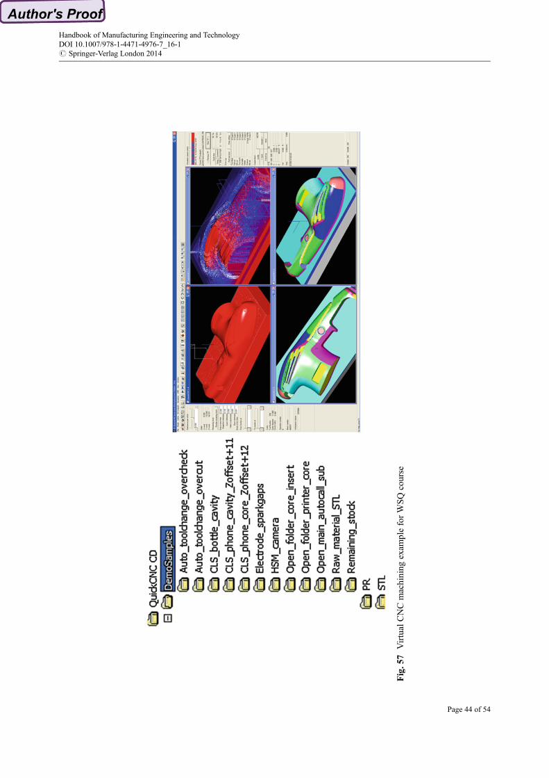
Fig.5
7VirtualCNCmachining
exam
pleforWSQcourse
Handbook of Manufacturing Engineering and TechnologyDOI 10.1007/978-1-4471-4976-7_16-1# Springer-Verlag London 2014
Page 44 of 54

companies, training of CNC machinists has been paid great attention. In partner with SIMTech,SPETA uses the system to train CNCmachinists – somewhat like the flight simulators to train pilots,which will significantly trim the training hours on the actual machine.
The system is also used in Institute for Technical Education (ITE) for training computer numericcontrol machinists. Significantly reducing the hours and machine resources required, the virtualCNC training system enables trainees to practice more with various machining requirements withinthe same allocated training time. With this additional preparation, trainees would have a shorterlearning cycle when they start working with the companies. Virtual CNC training has been featuredin local TV, radio, and all newspapers. Figure 59 highlighted virtual CNC training in Metal Asia(MTA) and Singapore Science Festival.
Profiting from Virtual Machining
Virtual machining is not a “nice to have” feature that focuses on trade show demonstrations. Thereare practical industrial applications which need virtual machining to complete, which include code
Fig. 58Q8 Virtual CNC training in practice
Fig. 59 Virtual CNC in MTA and science festival
Handbook of Manufacturing Engineering and TechnologyDOI 10.1007/978-1-4471-4976-7_16-1# Springer-Verlag London 2014
Page 45 of 54

parsing, toolpath backplot, trial cut replacement, adaptive speed-feedrate optimization and virtualtraining.
Just like all virtual manufacturing technologies, virtual machining has been ready for pervasiveindustry implementation for a long time. The only barrier was the high computing cost of UNIXgraphics workstations, such as Silicon Graphics, which were beyond the reach of small machiningworkshops. With the recent worldwide price surge in materials, energy and machine tool, pervasivevirtual machining is not only technically possible but also makes business sense, since computingcost is almost zero.
First Part RightAn NC program has thousands of lines of tool movement instructions that may contain errors.Following these instructions, CNC machine tool will move blindly, without any check on gauging,overcut or cutting force. It is not possible to verify code manually, so the NC verification softwarewas developed during the 1980s.
NC simulation features full 3D, solid model, shaded simulation of entire NC machine tools andmaterial removal. This visualization tool enables programmers and machinists alike to previewexactly what will happen on the shop floor and check for collisions. Many use NC simulation forelectronic shop floor documentation.
NC verification detects problems in the NC tool path program. It is a powerful visual inspectiontool, which highlights fast feed errors, gouges and potential crashes/collisions. Programmers candetect and correct problems before prove-out. With NC verification you can virtually eliminate NCprogram mistakes, greatly reduce the time spent on prove-outs, and make the move to “lights-out”machining. The NC simulation program is smart enough to detect problems such as fast feed errors,gouges and collisions that could potentially scrap the part, break the cutter or crash the machine. Anyerror discovered by simulating software allows the programmer to immediately identify theoffending NC program record by mouse-clicking on the error. The problem can therefore be fixedduring the NC coding phase so as to insure an error-free code when it reaches the shop floor.
NC analysis identifies the tool path record responsible for an error. You can quickly verify thedimensional accuracy of the entire part with a full array of 3D measurement tools. NC analysiscompares the simulated part to the design model so you can be sure the machined part will match thedesign intent. NC analysis performs constant gouge checking. Analysis of the “as-cut” part delvesdeeper into the verification process. Is the resulting cut part dimensionally accurate? Does it matchthe final desired part shape? NC verification software enables the user to zoom in on suspect areas forin-depth inspection. The part can be rotated and cross-sectioned at any angle to check areas thatwould otherwise be impossible to see, such as the intersection of drilled holes. Detailed measure-ment tools enable the user to verify dimensions such as wall and floor thickness, hole diameters,corner radii, scallop heights, depth, gaps, distances, angles, volumes, etc. NC simulation softwaresuch as VERICUT® from CGTech also provides the ability to automatically compare the as-cut partwith the original design. The AUTO-Diff module can embed the CAD design model inside thestock, automatically comparing the design to the in-process workpiece in order to reveal anydiscrepancies such as gouges or excess material not removed by the machining processes.
NC errors could destroy work pieces, even damage machine tool. One NC error could make theworkpiece a waste and take days to rework and eat into profit. In small batch production, there is notime for trial and error. Especially for high speed machining (HSM), the fast moving and expensivecutter is very easily broken. The dynamic machining load will greatly affect cutter life, geometryaccuracy and surface finishing.
Handbook of Manufacturing Engineering and TechnologyDOI 10.1007/978-1-4471-4976-7_16-1# Springer-Verlag London 2014
Page 46 of 54

The challenges also come from the huge tool path of HSM. A million lines of NC code arecommon practice in today’s shop floor. The traditional NC verification is so slow that even HSMitself is faster than verification. The size of the program combined with a high feed rate makes italmost impossible to run test simulations prior to cutting metal.
NC verification cannot rely on CPU of faster processing cycles as single-core silicon reaches thelimit of heat dissipation and power consumption. A processor containing multiple cores, leveragingits ability to execute multiple tasks, offers a higher level of computing power and functionality thanthe current generation single-core processor. As this new technology comes to market, softwarecompanies are examining how software will adapt. The current NC simulation models are notoptimized for multi-core computing as some software only run 12 % faster on a dual processorworkstation. How to split the NC simulation between dual-core and graphics card is a new R&Dchallenge.
Singapore Institute of Manufacturing Technology (SIMTech) has developed a more efficientapproach based on a patented geometry representation. The system starts with a solid model of themachined part and quickly simulates and optimizes machining processes. NC code could beselectively reverse post processed into 3D tool path graphics display and interactively viewed,edited and optimized. The user can highlight or hide operation, tool path or layer. The user can alsodisplay and edit a certain layer of toolpath. Tool paths and cutting results can be viewed from anyviewpoint and checked automatically. The machined part and the design part are compared for theremaining stock and over cut. Error-free tool paths are created, eliminating the need for a time-consuming test cut.
Based on this patented technique, SIMTech developed several practical applications for mouldmanufacturers. These include QuickSeeNC, QuickCNC and PartingAdviser, which provide “WhatYou See is What You Cut” functionality for shop floor machine operators and mould designers. Thetechnology is suitable for machine tool NC tool path simulation, verification and optimization in theprecision engineering, automotive, aerospace and electronics industries. QuickCNC has beenadopted by several local die and mould makers for its speed and simplicity.
Pervasive Virtual Applications in whole Process ChainsMoving beyond the NC programming department, virtual machining could be used pervasively allover whole process chains, such as part design, tool design, process planning and scheduling, tooldata management, material, setup, production and quality control, as shown in Fig. 60.
Engineers often need a method of getting a model of the as-manufactured part back into the CADsystem for a variety of reasons. It could be that the required CADmodel does not exist but legacy NCprogram data to create it does. Frequently the as-cut part contains features (fillets, blends, etc.) notpresent in the original CAD design and an accurate and complete model is needed for finite elementmodelling or environmental simulation or further engineering analysis. Often, simulating pseudoNC paths is the fastest and simplest way to create complex offset surface shapes.
Whatever the reason, NC simulation can create either surface or solid model representations of thesimulated machined part. The exported model can be either a surface or solid b-rep model withgeometric shapes (cylinder, cone, plane, torus sweep, etc.) that represent machined features such asdrilled holes, pocket corners and walls, filleted blends and other common manufacturing features.Very small machined features such as scallops created by ball-end mill contouring of complexshapes can be collected together into large surface patches representing the nominal feature intendedby the machining operation.
Handbook of Manufacturing Engineering and TechnologyDOI 10.1007/978-1-4471-4976-7_16-1# Springer-Verlag London 2014
Page 47 of 54

In-Process Geometry for Manufacturing EngineeringIn addition to design engineering’s need for an as-manufactured CAD model, other manufacturingengineering and planning functions could use the information.
It is difficult to imagine, plan and design all the resources required for subsequent operations(NC programs, fixtures, custom cutting tools, inspection tools, work handling devices, transfermethods, etc.) without an accurate representation of the initial material state left by the previousoperation. The accuracy, efficiency and “correctness” of each operation depend on the NC pro-grammer, tool designer and process planner knowing the material’s initial geometric shape. Untilnow, the only way to create an in-process CAD model was with expensive, labour-intensive, error-prone and inaccurate methods. However, exporting a CAD model of the in-process or as-machinedsolid model created automatically from the verification step makes it possible to avoid these time-consuming activities. Users can create the CAD model at any stage in the machining process.
Simulation for Process Planning, Scheduling, Production and QAIn order for process planners to do their job effectively, it is crucial to know accurate machiningtimes. This can be easily obtained by simulating the NC program. Times are calculated for every stepin the machining process including the amount of time it takes to change tools, pallets or othermiscellaneous machine actions. This information can be essential to keeping the production flooroperating to its full capacity.
Additionally, the process planners can use an in-process geometry model to create robustinspection instructions in very little time. Typically, a manufacturing engineer, NC programmer orprocess planner manually creates these instructions to tell the machine operator what to measure andhow to document the results. Without an in-process model of the part, manual methods are verytedious and prone to mistakes. The highly-customizable inspection instructions can be createdautomatically. This helps to establish a formal but easy and efficient method to create the necessarydocumentation. The software outputs the inspection instructions based on the dimensions of thesimulated cut stock (as-cut semi-finished wall thickness ¼ .1500, for example). The accuratein-process geometry is required to automatically generate this type of document, and is onlyavailable by simulating the NC program.
Documentation for WorkshopThe latest NC simulation system includes powerful tools for creating custom reports, tailored fora specific user/department/company’s needs, containing useful process information generatedduring the simulation. The automatically generated documents can be used for shop floor orin-process documentation, NC programming documentation or to capture valuable process infor-mation generated during the simulation session. Produced in standard HTML or PDF format, thereport layout is highly customizable, including the ability to specify page design, fonts, graphics,tables, pictures, statistics and user-defined information critical to documenting the CNC machiningprocess.
Simulating CAM output to view basic workpiece material removal is no longer enough in today’scompetitive global marketplace. It is critical to be operating as efficiently as possible; modernsimulation and optimization software has become a key tool to minimize the cost and time ofproduction while maintaining or increasing product quality. It has evolved into an important processthat protects and frees up CNC machines, helps to eliminate scraped parts, and creates in-processinformation that can be utilized throughout the manufacturing enterprise.
Handbook of Manufacturing Engineering and TechnologyDOI 10.1007/978-1-4471-4976-7_16-1# Springer-Verlag London 2014
Page 48 of 54

Adaptive Machining OptimizationCNC optimization automatically determines the best feed rate for each segment of the tool pathbased on the machining conditions and amount of material removed. Optimizing NC feed ratesgreatly reduces the time it takes to machine parts and improves the quality of surface finish.
After CNC verification and achieving error-free machining, the in-process model could be used toachieve faster machining, which is based on the calculated material removal rate.
The machining model, simulation and verification processes ensure that the NC programs sent tothe shop are both accurate and efficient. To create the most efficient machining processes possible,optimization software can determine the best feed rates to use for each cutting operation. Achievingthe best feed rates for each cut in an NC program has always been a goal for NC programmers but hastraditionally been a very difficult task plagued by a number of problems. First, trying to imagine thecutter contact and cutting conditions or each cut in a large NC program is virtually impossible.Manually inserting different feed rates for each changing condition is not practical. An incorrect feedrate estimate can break the cutting tool, damage the fixture or scrap the part.
Typically either a single conservative feed rate is used for an entire machining sequence, as shownin the left side of Fig. 61, or a higher (i.e., “high speed”) feed rate is used but with a very conservativemachining strategy. Both methods attempt to ensure that the cutter is not overloaded, but at theexpense of very inefficient machining. Both of these strategies result in too slow cutting speeds ortoo light removal rates that waste time, increase costs and prematurely wear cutters.
To address this issue, a knowledge-based machining package essentially adds intelligence to thecutter. During the simulation, the in-process geometrical model knows the exact depth, width andangle of each cut because the software also knows the exact shape of the in-process material at everyinstant of the machining sequence. It knows exactly how much material is removed by each cut
Fig. 60 Virtual applications in whole process chains
Handbook of Manufacturing Engineering and TechnologyDOI 10.1007/978-1-4471-4976-7_16-1# Springer-Verlag London 2014
Page 49 of 54
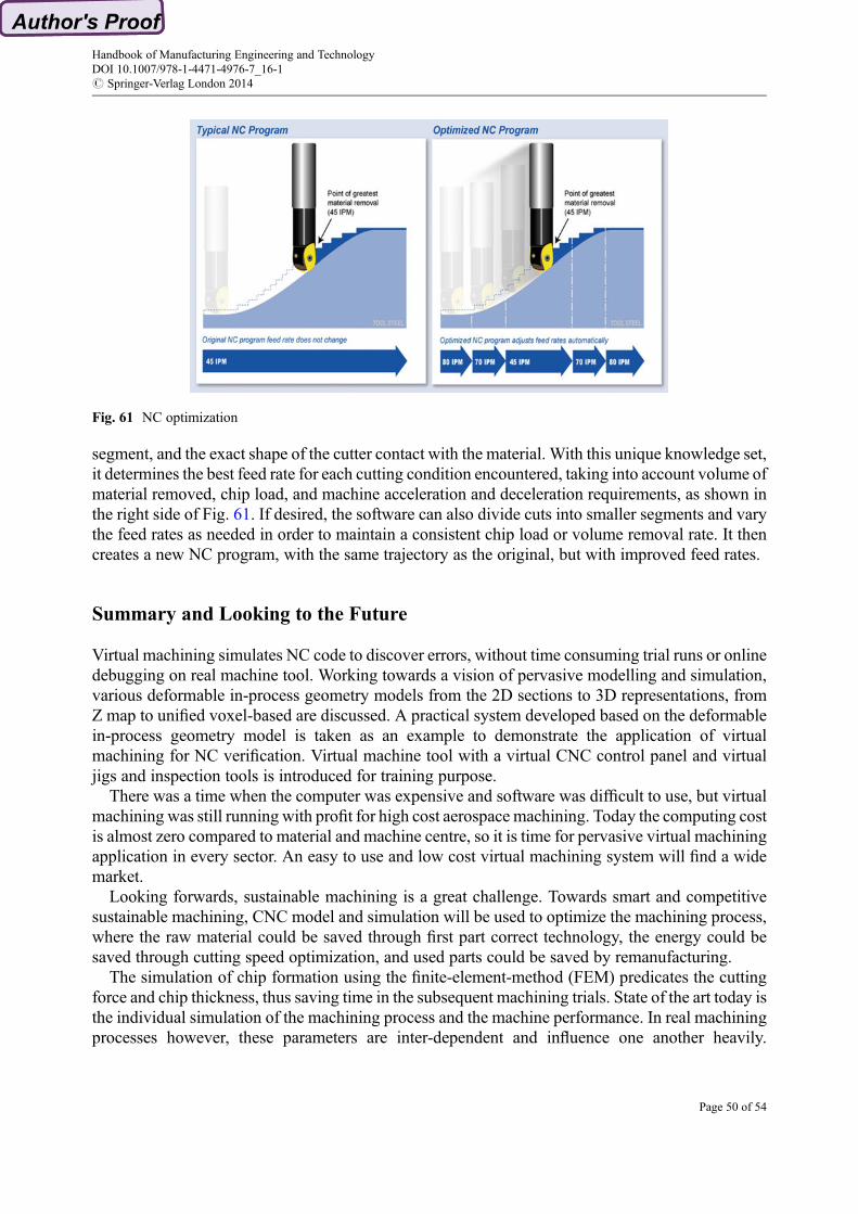
segment, and the exact shape of the cutter contact with the material. With this unique knowledge set,it determines the best feed rate for each cutting condition encountered, taking into account volume ofmaterial removed, chip load, and machine acceleration and deceleration requirements, as shown inthe right side of Fig. 61. If desired, the software can also divide cuts into smaller segments and varythe feed rates as needed in order to maintain a consistent chip load or volume removal rate. It thencreates a new NC program, with the same trajectory as the original, but with improved feed rates.
Summary and Looking to the Future
Virtual machining simulates NC code to discover errors, without time consuming trial runs or onlinedebugging on real machine tool. Working towards a vision of pervasive modelling and simulation,various deformable in-process geometry models from the 2D sections to 3D representations, fromZ map to unified voxel-based are discussed. A practical system developed based on the deformablein-process geometry model is taken as an example to demonstrate the application of virtualmachining for NC verification. Virtual machine tool with a virtual CNC control panel and virtualjigs and inspection tools is introduced for training purpose.
There was a time when the computer was expensive and software was difficult to use, but virtualmachining was still running with profit for high cost aerospace machining. Today the computing costis almost zero compared to material and machine centre, so it is time for pervasive virtual machiningapplication in every sector. An easy to use and low cost virtual machining system will find a widemarket.
Looking forwards, sustainable machining is a great challenge. Towards smart and competitivesustainable machining, CNC model and simulation will be used to optimize the machining process,where the raw material could be saved through first part correct technology, the energy could besaved through cutting speed optimization, and used parts could be saved by remanufacturing.
The simulation of chip formation using the finite-element-method (FEM) predicates the cuttingforce and chip thickness, thus saving time in the subsequent machining trials. State of the art today isthe individual simulation of the machining process and the machine performance. In real machiningprocesses however, these parameters are inter-dependent and influence one another heavily.
Fig. 61 NC optimization
Handbook of Manufacturing Engineering and TechnologyDOI 10.1007/978-1-4471-4976-7_16-1# Springer-Verlag London 2014
Page 50 of 54
Integrated simulation, whereby the process-machine interaction is simulated, is therefore a furtherkey technology for sustainable production in the future.
Tool chatter is the barrier for higher material removal rate and can damage machine tool spindle.A certain combination of depth of cut and speed can incur self excited vibration of tooling systemand generate cutter marks on the machined surface. Dynamic machining model and simulation canpredicate best cutting speed and depth combination that will cut faster without chattering.
The simulation of machining operations offers the potential to fulfil the ecological, social andeconomic requirements of sustainability. For example, the adjustment of the suitable feed rate in themilling of complex geometries from difficult to machine materials may be optimized throughsimulation and thus reduce the machining time by up to 40 %. The resultant reduction in consumedresources allows a saving of both costs and energy.
The machining stock is the volume difference between the designed part geometry and rawmaterial geometry. Reducing the machining stock can save raw material. The minimum machiningstock could be achieved through near net shape forming of the raw material, such as casting, forgingand welding.
The most material and energy are wasted in the manufacturing processes. These wastes can besaved through re-machining of the damaged component, where the damage can be repaired bywelding or thermal spray. For a long time in the aerospace industry, overhaul of jet engines has beena profitable business worldwide. Nowadays even the automotive industry has started tore-manufacture many components, especially engines. However, re-machining is a great challengefor CNC machining since the damaged component geometry is warped. Virtual machining cansimulate this warped component and generate 3D printing and the following cleanup toolpath.
ReferenceQ3 s
Q4 AbdulKadir A et al (2011) Virtual machine tools and virtual machining – a technological review.Robot Comput Integr Manuf 27:494–508
Avgoustinov N (2000) VRML asmeans of expressive 4D illustration in CAM education. Future GenComput Syst 17:39–48
Q5 Chandru V, Manohar S, Prakash CE (1995) Voxel-based modeling for layered manufacturing. IEEEComput Graph Appl 15(6):42–47
Donggo J, Kwangsoo K, Jungmin J (2000) Voxel-based virtual multi-axis machining. Int J AdvManuf Technol 16(10):709–713
Garcia-Plaza E et al (2011) Virtual Machining applied to the teaching of manufacturing technology.Mater Sci Forum 692(2011):120–127
http://www.engineeringchallenges.orgJerard RB, Hussaini SZ, Drysdale RL, Schaudt B (1989) Approximate methods for simulation and
verification of numerically controlled machining programs. Vis Comput 5(4):329–348Q6 Kase K, Teshima Y, Usami S, Ohmori H, Teodosiu C, Makinouchi A (2003) Volume CAD. In:
Proceedings of the 2003 Eurographics/IEEE TVCG workshop on volume graphics VG ‘03Liu PL (2005) Profiting from dynamic numerical control verification system. Cutting Edge News-
letter of SIMTech, Issue 43. http://www.simtech.a-star.edu.sg/index-publication.htmlQ7 Liu PL et al (1991) A new concept integrated CAD/CAM system for complicated die and mold. In:
Advances in computer science application to machinery. International Academic Publisher,pp 90–95. ISBN 7-8003-154-3/TH.2
Handbook of Manufacturing Engineering and TechnologyDOI 10.1007/978-1-4471-4976-7_16-1# Springer-Verlag London 2014
Page 51 of 54

Liu PL et al (1992) 3D Complicated parts design based on the automatic shape generation. ChinJ Mech Eng (English Edition) 5(2):88–92
Liu PL, Lu YQ, AO YT (2002) An object representation method, WO04032001A1Maenga SR, Baekc N, Shinb SY, Choid BK (2003) A Z-Map update method for linearly moving
tools. Comput Aided Des 35:995–1009Nakashima T, Ishihara Y, Niiyama K, Makinouchi A (2002) Development of stress analysis system
by X-FEM with voxel-type mesh. In: Proceedings of the fifth world congress on computationalmechanics (WCCM V), Vienna
Park SC, Mukundan G, Gu S, Olling GJ (2003) In-process model generation for the processplanning of a prismatic part. J Adv Manuf Syst 2(2):147–162
Stifter S (1995) Simulation of NC machining based on the dexel model: a critical analysis. Int J AdvManuf Technol 10(3):149–157
Handbook of Manufacturing Engineering and TechnologyDOI 10.1007/978-1-4471-4976-7_16-1# Springer-Verlag London 2014
Page 52 of 54

Index Terms:
3D printing 24Extended Z buffer method 9Extended Z Map 16In-process model (IPM) 12Layered manufacturing 22Machine tool 5ModuleWorks™ 4Numerical control (NC) 2, 4, 46, 49
optimization 49simulation 4, 46verification 2, 46
Octree hierarchical space decomposition 21QuickCNC GUI 26Reverse post processing 7Stick method 17Uniform space decomposition (USD) 20VERICUT composite simulation 25Virtual machining 1Voxel model 22Z Map model 16
Handbook of Manufacturing Engineering and TechnologyDOI 10.1007/978-1-4471-4976-7_16-1# Springer-Verlag London 2014
Page 53 of 54

Author Queries
Query Refs. Details Required
Q1 Please check if affiliation details are okay.
Q2 Please provide details fo Refs. [17–19] in the reference list.
Q3 Please cite “http://www.engineeringchallenges.org” in text.
Q4 Please provide complete details of “http://www.engineeringchallenges.org”.
Q5 Please check if inserted page range for Chandru et al. (1995) is okay.
Q6 Please provide proceeding location of Kase et al. (2003).
Q7 Please provide publisher location for Liu et al. (1991).
Q8 Figure 58 is found to be poor in quality. Please provide better quality of figures if available.
Handbook of Manufacturing Engineering and TechnologyDOI 10.1007/978-1-4471-4976-7_16-1# Springer-Verlag London 2014
Page 54 of 54