virtual machining using camworks 2021
TRANSCRIPT
Chang
Virtual MachiningCAMWorks 2021
CAMWorks as a SOLIDWORKS Module
Kuang-Hua Chang, Ph.D.
Using
®
®
Better Textbooks
Lower Prices
SD
C SDCP U B L I C AT I O N S www.SDCpublications.com
Better Textbooks. Lower Prices.

Visit the following websites to learn more about this book:
Powered by TCPDF (www.tcpdf.org)
Lesson 1: Introduction to CAMWorks 1
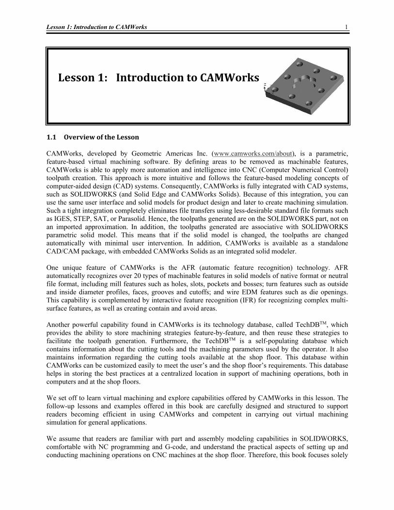
Lesson 1: Introduction to CAMWorks 1.1 Overview of the Lesson CAMWorks, developed by Geometric Americas Inc. (www.camworks.com/about), is a parametric, feature-based virtual machining software. By defining areas to be removed as machinable features, CAMWorks is able to apply more automation and intelligence into CNC (Computer Numerical Control) toolpath creation. This approach is more intuitive and follows the feature-based modeling concepts of computer-aided design (CAD) systems. Consequently, CAMWorks is fully integrated with CAD systems, such as SOLIDWORKS (and Solid Edge and CAMWorks Solids). Because of this integration, you can use the same user interface and solid models for product design and later to create machining simulation. Such a tight integration completely eliminates file transfers using less-desirable standard file formats such as IGES, STEP, SAT, or Parasolid. Hence, the toolpaths generated are on the SOLIDWORKS part, not on an imported approximation. In addition, the toolpaths generated are associative with SOLIDWORKS parametric solid model. This means that if the solid model is changed, the toolpaths are changed automatically with minimal user intervention. In addition, CAMWorks is available as a standalone CAD/CAM package, with embedded CAMWorks Solids as an integrated solid modeler. One unique feature of CAMWorks is the AFR (automatic feature recognition) technology. AFR automatically recognizes over 20 types of machinable features in solid models of native format or neutral file format, including mill features such as holes, slots, pockets and bosses; turn features such as outside and inside diameter profiles, faces, grooves and cutoffs; and wire EDM features such as die openings. This capability is complemented by interactive feature recognition (IFR) for recognizing complex multi-surface features, as well as creating contain and avoid areas. Another powerful capability found in CAMWorks is its technology database, called TechDBTM, which provides the ability to store machining strategies feature-by-feature, and then reuse these strategies to facilitate the toolpath generation. Furthermore, the TechDBTM is a self-populating database which contains information about the cutting tools and the machining parameters used by the operator. It also maintains information regarding the cutting tools available at the shop floor. This database within CAMWorks can be customized easily to meet the user’s and the shop floor’s requirements. This database helps in storing the best practices at a centralized location in support of machining operations, both in computers and at the shop floors. We set off to learn virtual machining and explore capabilities offered by CAMWorks in this lesson. The follow-up lessons and examples offered in this book are carefully designed and structured to support readers becoming efficient in using CAMWorks and competent in carrying out virtual machining simulation for general applications. We assume that readers are familiar with part and assembly modeling capabilities in SOLIDWORKS, comfortable with NC programming and G-code, and understand the practical aspects of setting up and conducting machining operations on CNC machines at the shop floor. Therefore, this book focuses solely
2 Lesson 1: Introduction to CAMWorks
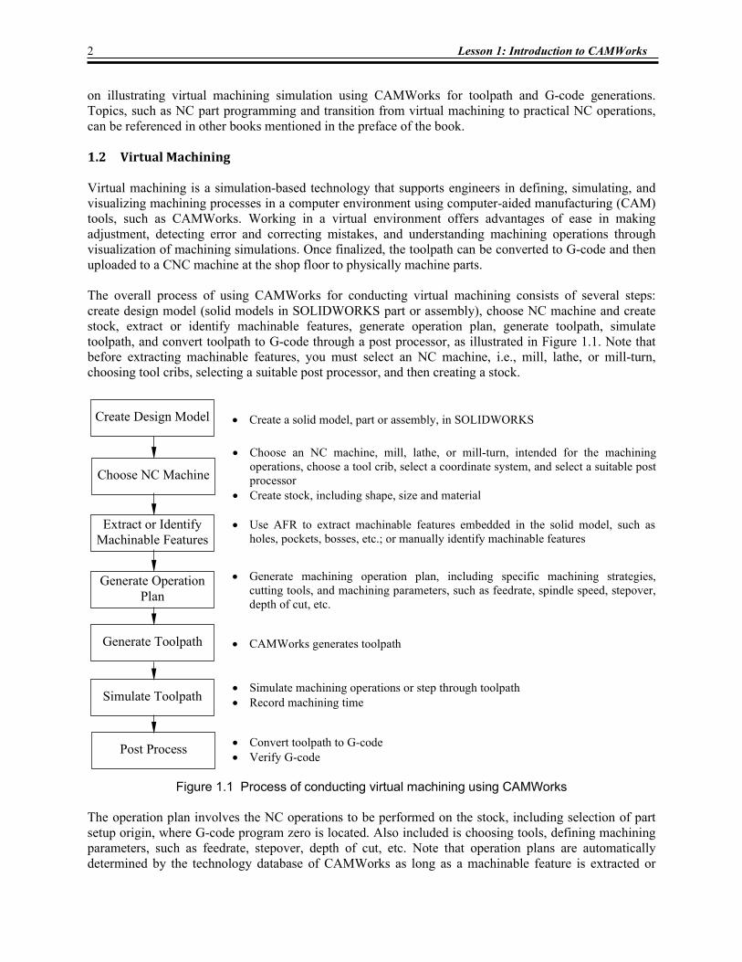
on illustrating virtual machining simulation using CAMWorks for toolpath and G-code generations. Topics, such as NC part programming and transition from virtual machining to practical NC operations, can be referenced in other books mentioned in the preface of the book. 1.2 Virtual Machining Virtual machining is a simulation-based technology that supports engineers in defining, simulating, and visualizing machining processes in a computer environment using computer-aided manufacturing (CAM) tools, such as CAMWorks. Working in a virtual environment offers advantages of ease in making adjustment, detecting error and correcting mistakes, and understanding machining operations through visualization of machining simulations. Once finalized, the toolpath can be converted to G-code and then uploaded to a CNC machine at the shop floor to physically machine parts. The overall process of using CAMWorks for conducting virtual machining consists of several steps: create design model (solid models in SOLIDWORKS part or assembly), choose NC machine and create stock, extract or identify machinable features, generate operation plan, generate toolpath, simulate toolpath, and convert toolpath to G-code through a post processor, as illustrated in Figure 1.1. Note that before extracting machinable features, you must select an NC machine, i.e., mill, lathe, or mill-turn, choosing tool cribs, selecting a suitable post processor, and then creating a stock.
Figure 1.1 Process of conducting virtual machining using CAMWorks The operation plan involves the NC operations to be performed on the stock, including selection of part setup origin, where G-code program zero is located. Also included is choosing tools, defining machining parameters, such as feedrate, stepover, depth of cut, etc. Note that operation plans are automatically determined by the technology database of CAMWorks as long as a machinable feature is extracted or
• Create a solid model, part or assembly, in SOLIDWORKS
• Use AFR to extract machinable features embedded in the solid model, such as holes, pockets, bosses, etc.; or manually identify machinable features
• Generate machining operation plan, including specific machining strategies, cutting tools, and machining parameters, such as feedrate, spindle speed, stepover, depth of cut, etc.
• Simulate machining operations or step through toolpath • Record machining time
• Convert toolpath to G-code • Verify G-code
• CAMWorks generates toolpath
Create Design Model
Extract or Identify Machinable Features
Generate Operation Plan
Generate Toolpath
Simulate Toolpath
Post Process
Choose NC Machine
• Choose an NC machine, mill, lathe, or mill-turn, intended for the machining operations, choose a tool crib, select a coordinate system, and select a suitable post processor
• Create stock, including shape, size and material
Lesson 1: Introduction to CAMWorks 3
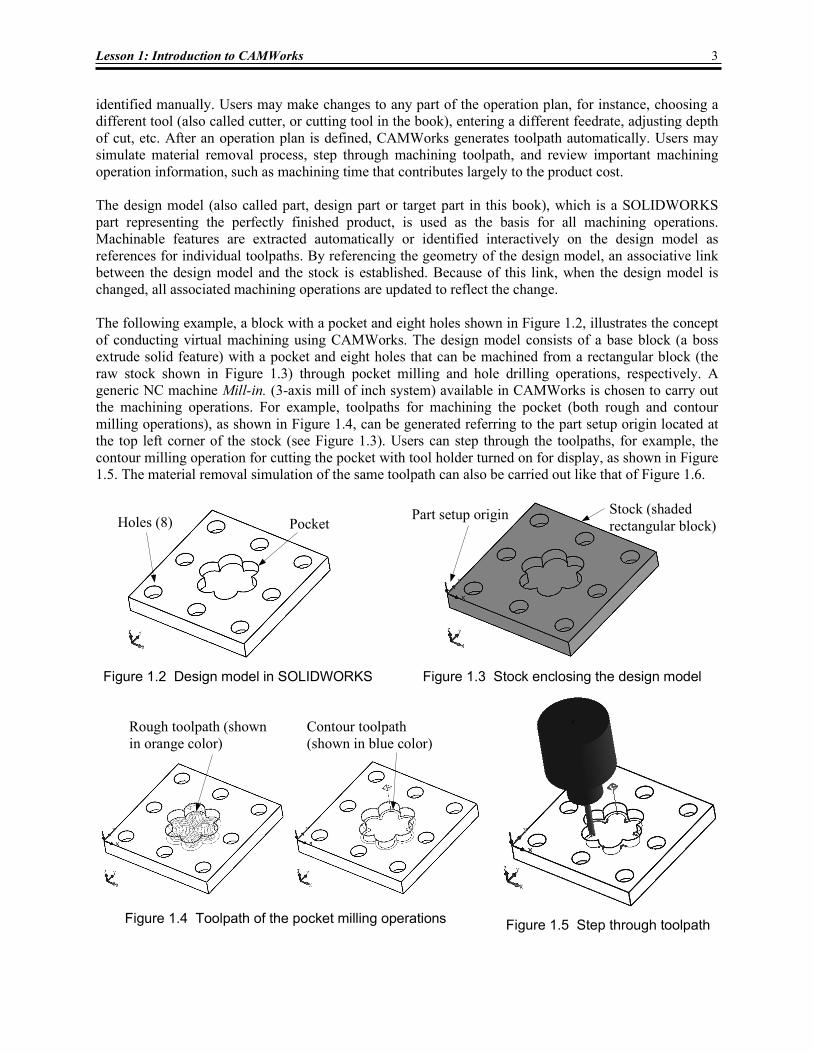
identified manually. Users may make changes to any part of the operation plan, for instance, choosing a different tool (also called cutter, or cutting tool in the book), entering a different feedrate, adjusting depth of cut, etc. After an operation plan is defined, CAMWorks generates toolpath automatically. Users may simulate material removal process, step through machining toolpath, and review important machining operation information, such as machining time that contributes largely to the product cost. The design model (also called part, design part or target part in this book), which is a SOLIDWORKS part representing the perfectly finished product, is used as the basis for all machining operations. Machinable features are extracted automatically or identified interactively on the design model as references for individual toolpaths. By referencing the geometry of the design model, an associative link between the design model and the stock is established. Because of this link, when the design model is changed, all associated machining operations are updated to reflect the change. The following example, a block with a pocket and eight holes shown in Figure 1.2, illustrates the concept of conducting virtual machining using CAMWorks. The design model consists of a base block (a boss extrude solid feature) with a pocket and eight holes that can be machined from a rectangular block (the raw stock shown in Figure 1.3) through pocket milling and hole drilling operations, respectively. A generic NC machine Mill-in. (3-axis mill of inch system) available in CAMWorks is chosen to carry out the machining operations. For example, toolpaths for machining the pocket (both rough and contour milling operations), as shown in Figure 1.4, can be generated referring to the part setup origin located at the top left corner of the stock (see Figure 1.3). Users can step through the toolpaths, for example, the contour milling operation for cutting the pocket with tool holder turned on for display, as shown in Figure 1.5. The material removal simulation of the same toolpath can also be carried out like that of Figure 1.6.
Figure 1.2 Design model in SOLIDWORKS
Pocket Holes (8)
Figure 1.5 Step through toolpath Figure 1.4 Toolpath of the pocket milling operations
Rough toolpath (shown in orange color)
Contour toolpath (shown in blue color)
Figure 1.3 Stock enclosing the design model
Stock (shaded rectangular block)
Part setup origin
4 Lesson 1: Introduction to CAMWorks
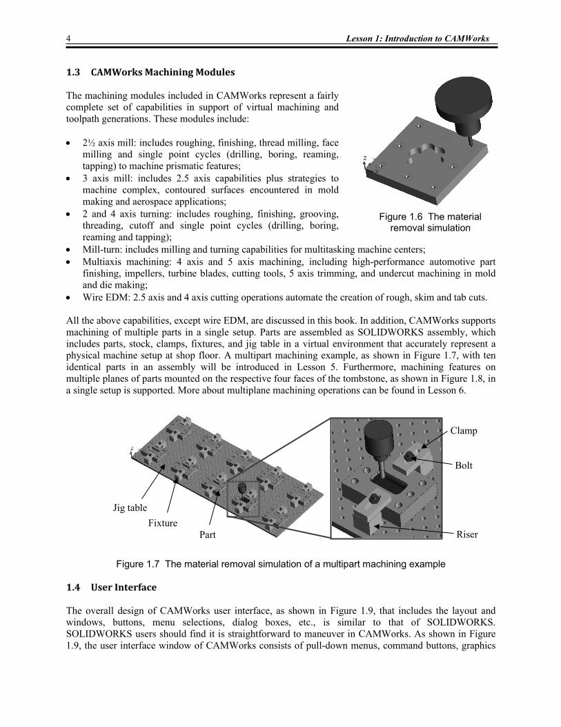
1.3 CAMWorks Machining Modules The machining modules included in CAMWorks represent a fairly complete set of capabilities in support of virtual machining and toolpath generations. These modules include: • 2½ axis mill: includes roughing, finishing, thread milling, face
milling and single point cycles (drilling, boring, reaming, tapping) to machine prismatic features;
• 3 axis mill: includes 2.5 axis capabilities plus strategies to machine complex, contoured surfaces encountered in mold making and aerospace applications;
• 2 and 4 axis turning: includes roughing, finishing, grooving, threading, cutoff and single point cycles (drilling, boring, reaming and tapping);
• Mill-turn: includes milling and turning capabilities for multitasking machine centers; • Multiaxis machining: 4 axis and 5 axis machining, including high-performance automotive part
finishing, impellers, turbine blades, cutting tools, 5 axis trimming, and undercut machining in mold and die making;
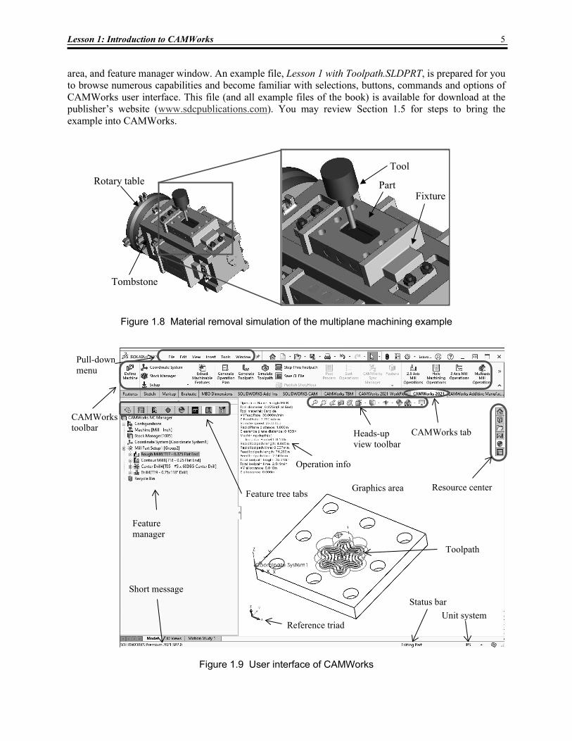
• Wire EDM: 2.5 axis and 4 axis cutting operations automate the creation of rough, skim and tab cuts. All the above capabilities, except wire EDM, are discussed in this book. In addition, CAMWorks supports machining of multiple parts in a single setup. Parts are assembled as SOLIDWORKS assembly, which includes parts, stock, clamps, fixtures, and jig table in a virtual environment that accurately represent a physical machine setup at shop floor. A multipart machining example, as shown in Figure 1.7, with ten identical parts in an assembly will be introduced in Lesson 5. Furthermore, machining features on multiple planes of parts mounted on the respective four faces of the tombstone, as shown in Figure 1.8, in a single setup is supported. More about multiplane machining operations can be found in Lesson 6.
Figure 1.7 The material removal simulation of a multipart machining example 1.4 User Interface The overall design of CAMWorks user interface, as shown in Figure 1.9, that includes the layout and windows, buttons, menu selections, dialog boxes, etc., is similar to that of SOLIDWORKS. SOLIDWORKS users should find it is straightforward to maneuver in CAMWorks. As shown in Figure 1.9, the user interface window of CAMWorks consists of pull-down menus, command buttons, graphics
Figure 1.6 The material
removal simulation
Jig table Fixture
Part Riser
Clamp
Bolt
Lesson 1: Introduction to CAMWorks 5
area, and feature manager window. An example file, Lesson 1 with Toolpath.SLDPRT, is prepared for you to browse numerous capabilities and become familiar with selections, buttons, commands and options of CAMWorks user interface. This file (and all example files of the book) is available for download at the publisher’s website (www.sdcpublications.com). You may review Section 1.5 for steps to bring the example into CAMWorks.
Figure 1.8 Material removal simulation of the multiplane machining example
Figure 1.9 User interface of CAMWorks
Feature manager
Status bar
Graphics area Resource center Feature tree tabs
Heads-up view toolbar
Reference triad
CAMWorks tab
Unit system
CAMWorks toolbar
Pull-down menu
Short message
Rotary table
Tombstone
Toolpath
Fixture
Tool
Part
Operation info
6 Lesson 1: Introduction to CAMWorks
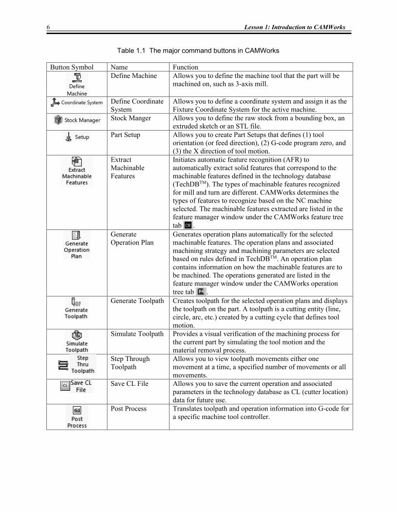
Table 1.1 The major command buttons in CAMWorks Button Symbol Name Function
Define Machine Allows you to define the machine tool that the part will be machined on, such as 3-axis mill.
Define Coordinate System
Allows you to define a coordinate system and assign it as the Fixture Coordinate System for the active machine.
Stock Manger Allows you to define the raw stock from a bounding box, an extruded sketch or an STL file.
Part Setup Allows you to create Part Setups that defines (1) tool orientation (or feed direction), (2) G-code program zero, and (3) the X direction of tool motion.
Extract Machinable Features
Initiates automatic feature recognition (AFR) to automatically extract solid features that correspond to the machinable features defined in the technology database (TechDBTM). The types of machinable features recognized for mill and turn are different. CAMWorks determines the types of features to recognize based on the NC machine selected. The machinable features extracted are listed in the feature manager window under the CAMWorks feature tree tab .
Generate Operation Plan
Generates operation plans automatically for the selected machinable features. The operation plans and associated machining strategy and machining parameters are selected based on rules defined in TechDBTM. An operation plan contains information on how the machinable features are to be machined. The operations generated are listed in the feature manager window under the CAMWorks operation tree tab .
Generate Toolpath Creates toolpath for the selected operation plans and displays the toolpath on the part. A toolpath is a cutting entity (line, circle, arc, etc.) created by a cutting cycle that defines tool motion.
Simulate Toolpath Provides a visual verification of the machining process for the current part by simulating the tool motion and the material removal process.
Step Through Toolpath
Allows you to view toolpath movements either one movement at a time, a specified number of movements or all movements.
Save CL File Allows you to save the current operation and associated parameters in the technology database as CL (cutter location) data for future use.
Post Process Translates toolpath and operation information into G-code for a specific machine tool controller.
Lesson 1: Introduction to CAMWorks 7
The graphics area displays the solid or machining simulation model with which you are working. The pull-down menus provide basic solid modeling functions in SOLIDWORKS and machining functions in CAMWorks. The command buttons of the CAMWorks tab above the graphics area offer all the functions required to create and modify virtual machining operations in a generic order. Major buttons include extract machinable features, generate operation plan, generate toolpath, simulate toolpath, step through toolpath, save CL file, and post process. When you move the mouse pointer over these buttons, a short message describing the menu command will appear. Some of the frequently used buttons in CAMWorks and their functions are also summarized in Table 1.1 for your reference.
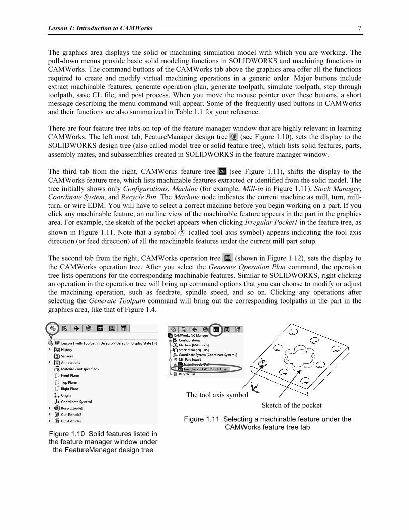
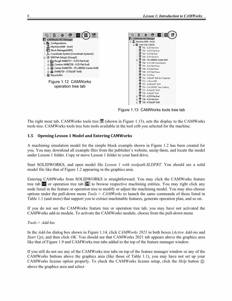
There are four feature tree tabs on top of the feature manager window that are highly relevant in learning CAMWorks. The left most tab, FeatureManager design tree (see Figure 1.10), sets the display to the SOLIDWORKS design tree (also called model tree or solid feature tree), which lists solid features, parts, assembly mates, and subassemblies created in SOLIDWORKS in the feature manager window. The third tab from the right, CAMWorks feature tree (see Figure 1.11), shifts the display to the CAMWorks feature tree, which lists machinable features extracted or identified from the solid model. The tree initially shows only Configurations, Machine (for example, Mill-in in Figure 1.11), Stock Manager, Coordinate System, and Recycle Bin. The Machine node indicates the current machine as mill, turn, mill-turn, or wire EDM. You will have to select a correct machine before you begin working on a part. If you click any machinable feature, an outline view of the machinable feature appears in the part in the graphics area. For example, the sketch of the pocket appears when clicking Irregular Pocket1 in the feature tree, as shown in Figure 1.11. Note that a symbol (called tool axis symbol) appears indicating the tool axis direction (or feed direction) of all the machinable features under the current mill part setup. The second tab from the right, CAMWorks operation tree (shown in Figure 1.12), sets the display to the CAMWorks operation tree. After you select the Generate Operation Plan command, the operation tree lists operations for the corresponding machinable features. Similar to SOLIDWORKS, right clicking an operation in the operation tree will bring up command options that you can choose to modify or adjust the machining operation, such as feedrate, spindle speed, and so on. Clicking any operations after selecting the Generate Toolpath command will bring out the corresponding toolpaths in the part in the graphics area, like that of Figure 1.4.
Figure 1.10 Solid features listed in the feature manager window under
the FeatureManager design tree
Figure 1.11 Selecting a machinable feature under the CAMWorks feature tree tab
Sketch of the pocket The tool axis symbol
8 Lesson 1: Introduction to CAMWorks
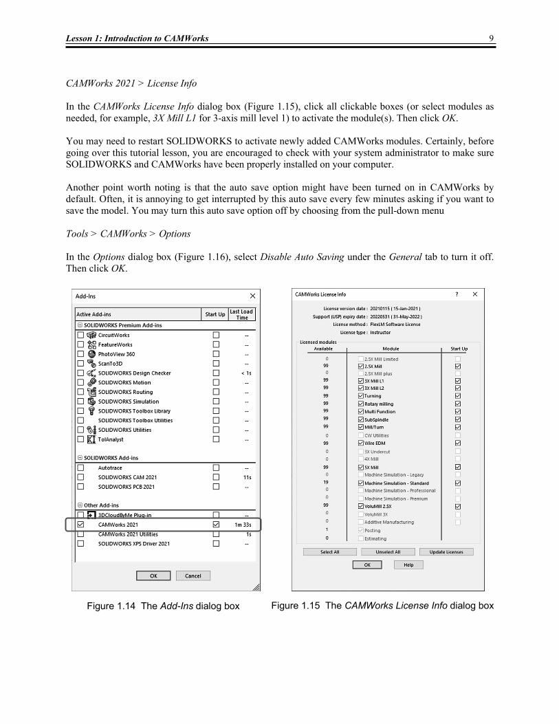
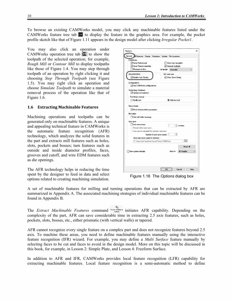
The right most tab, CAMWorks tools tree (shown in Figure 1.13), sets the display to the CAMWorks tools tree. CAMWorks tools tree lists tools available in the tool crib you selected for the machine. 1.5 Opening Lesson 1 Model and Entering CAMWorks A machining simulation model for the simple block example shown in Figure 1.2 has been created for you. You may download all example files from the publisher’s website, unzip them, and locate the model under Lesson 1 folder. Copy or move Lesson 1 folder to your hard drive. Start SOLIDWORKS, and open model file Lesson 1 with toolpath.SLDPRT. You should see a solid model file like that of Figure 1.2 appearing in the graphics area. Entering CAMWorks from SOLIDWORKS is straightforward. You may click the CAMWorks feature tree tab or operation tree tab to browse respective machining entities. You may right click any node listed in the feature or operation tree to modify or adjust the machining model. You may also choose options under the pull-down menu Tools > CAMWorks to launch the same commands of those listed in Table 1.1 (and more) that support you to extract machinable features, generate operation plan, and so on. If you do not see the CAMWorks feature tree or operation tree tab, you may have not activated the CAMWorks add-in module. To activate the CAMWorks module, choose from the pull-down menu Tools > Add-Ins In the Add-Ins dialog box shown in Figure 1.14, click CAMWorks 2021 in both boxes (Active Add-ins and Start Up), and then click OK. You should see that CAMWorks 2021 tab appears above the graphics area like that of Figure 1.9 and CAMWorks tree tabs added to the top of the feature manager window. If you still do not see any of the CAMWorks tree tabs on top of the feature manager window or any of the CAMWorks buttons above the graphics area (like those of Table 1.1), you may have not set up your CAMWorks license option properly. To check the CAMWorks license setup, click the Help button above the graphics area and select
Figure 1.12 CAMWorks
operation tree tab
Figure 1.13 CAMWorks tools tree tab
Lesson 1: Introduction to CAMWorks 9
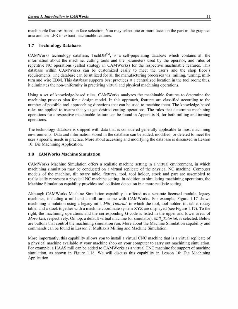
CAMWorks 2021 > License Info In the CAMWorks License Info dialog box (Figure 1.15), click all clickable boxes (or select modules as needed, for example, 3X Mill L1 for 3-axis mill level 1) to activate the module(s). Then click OK. You may need to restart SOLIDWORKS to activate newly added CAMWorks modules. Certainly, before going over this tutorial lesson, you are encouraged to check with your system administrator to make sure SOLIDWORKS and CAMWorks have been properly installed on your computer. Another point worth noting is that the auto save option might have been turned on in CAMWorks by default. Often, it is annoying to get interrupted by this auto save every few minutes asking if you want to save the model. You may turn this auto save option off by choosing from the pull-down menu Tools > CAMWorks > Options In the Options dialog box (Figure 1.16), select Disable Auto Saving under the General tab to turn it off. Then click OK.
Figure 1.14 The Add-Ins dialog box
Figure 1.15 The CAMWorks License Info dialog box
10 Lesson 1: Introduction to CAMWorks
To browse an existing CAMWorks model, you may click any machinable features listed under the CAMWorks feature tree tab to display the feature in the graphics area. For example, the pocket profile sketch like that of Figure 1.11 appears in the design model after clicking Irregular Pocket1. You may also click an operation under CAMWorks operation tree tab to show the toolpath of the selected operation; for example, Rough Mill or Contour Mill to display toolpaths like those of Figure 1.4. You may step through toolpath of an operation by right clicking it and choosing Step Through Toolpath (see Figure 1.5). You may right click an operation and choose Simulate Toolpath to simulate a material removal process of the operation like that of Figure 1.6. 1.6 Extracting Machinable Features Machining operations and toolpaths can be generated only on machinable features. A unique and appealing technical feature in CAMWorks is the automatic feature recognition (AFR) technology, which analyzes the solid features in the part and extracts mill features such as holes, slots, pockets and bosses; turn features such as outside and inside diameter profiles, faces, grooves and cutoff, and wire EDM features such as die openings. The AFR technology helps in reducing the time spent by the designer to feed in data and select options related to creating machining simulation. A set of machinable features for milling and turning operations that can be extracted by AFR are summarized in Appendix A. The associated machining strategies of individual machinable features can be found in Appendix B.
The Extract Machinable Features command initiates AFR capability. Depending on the complexity of the part, AFR can save considerable time in extracting 2.5 axis features, such as holes, pockets, slots, bosses, etc., either prismatic (with vertical walls) or tapered. AFR cannot recognize every single feature on a complex part and does not recognize features beyond 2.5 axis. To machine these areas, you need to define machinable features manually using the interactive feature recognition (IFR) wizard. For example, you may define a Multi Surface feature manually by selecting faces to be cut and faces to avoid in the design model. More on this topic will be discussed in this book, for example, in Lesson 2: Simple Plate, and Lesson 4: Freeform Surface. In addition to AFR and IFR, CAMWorks provides local feature recognition (LFR) capability for extracting machinable features. Local feature recognition is a semi-automatic method to define
Figure 1.16 The Options dialog box
Lesson 1: Introduction to CAMWorks 11
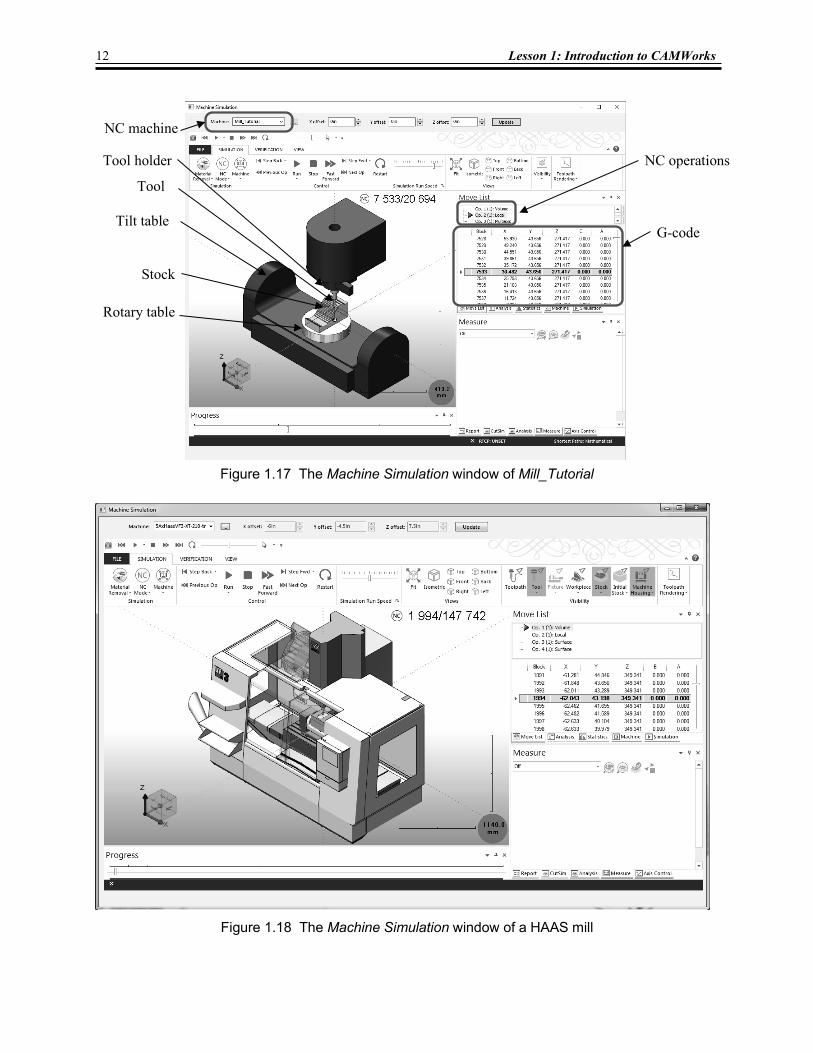
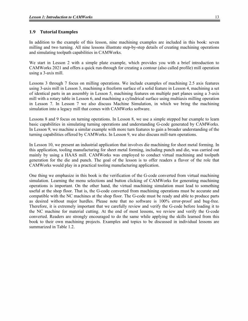
machinable features based on face selection. You may select one or more faces on the part in the graphics area and use LFR to extract machinable features. 1.7 Technology Database CAMWorks technology database, TechDBTM, is a self-populating database which contains all the information about the machine, cutting tools and the parameters used by the operator, and rules of repetitive NC operations (called strategy in CAMWorks) for the respective machinable features. This database within CAMWorks can be customized easily to meet the user’s and the shop floor’s requirements. The database can be utilized for all the manufacturing processes viz. milling, turning, mill-turn and wire EDM. This database supports best practices at a centralized location in the tool room; thus, it eliminates the non-uniformity in practicing virtual and physical machining operations. Using a set of knowledge-based rules, CAMWorks analyzes the machinable features to determine the machining process plan for a design model. In this approach, features are classified according to the number of possible tool approaching directions that can be used to machine them. The knowledge-based rules are applied to assure that you get desired cutting operations. The rules that determine machining operations for a respective machinable feature can be found in Appendix B, for both milling and turning operations. The technology database is shipped with data that is considered generally applicable to most machining environments. Data and information stored in the database can be added, modified, or deleted to meet the user’s specific needs in practice. More about accessing and modifying the database is discussed in Lesson 10: Die Machining Application. 1.8 CAMWorks Machine Simulation CAMWorks Machine Simulation offers a realistic machine setting in a virtual environment, in which machining simulation may be conducted on a virtual replicate of the physical NC machine. Computer models of the machine, tilt rotary table, fixtures, tool, tool holder, stock and part are assembled to realistically represent a physical NC machine setting. In addition to simulating machining operations, the Machine Simulation capability provides tool collision detection in a more realistic setting. Although CAMWorks Machine Simulation capability is offered as a separate licensed module, legacy machines, including a mill and a mill-turn, come with CAMWorks. For example, Figure 1.17 shows machining simulation using a legacy mill, Mill_Tutorial, in which the tool, tool holder, tilt table, rotary table, and a stock together with a machine coordinate system XYZ are displayed (see Figure 1.17). To the right, the machining operations and the corresponding G-code is listed in the upper and lower areas of Move List, respectively. On top, a default virtual machine (or simulator), Mill_Tutorial, is selected. Below are buttons that control the machining simulation run. More about the Machine Simulation capability and commands can be found in Lesson 7: Multiaxis Milling and Machine Simulation. More importantly, this capability allows you to install a virtual CNC machine that is a virtual replicate of a physical machine available at your machine shop on your computer to carry out machining simulation. For example, a HAAS mill can be added to CAMWorks as a virtual CNC machine for support of machine simulation, as shown in Figure 1.18. We will discuss this capability in Lesson 10: Die Machining Application.
12 Lesson 1: Introduction to CAMWorks
Figure 1.17 The Machine Simulation window of Mill_Tutorial
Figure 1.18 The Machine Simulation window of a HAAS mill
NC operations Tool holder
G-code
Stock
Tilt table
Rotary table
Tool
NC machine
Lesson 1: Introduction to CAMWorks 13
1.9 Tutorial Examples In addition to the example of this lesson, nine machining examples are included in this book: seven milling and two turning. All nine lessons illustrate step-by-step details of creating machining operations and simulating toolpath capabilities in CAMWorks. We start in Lesson 2 with a simple plate example, which provides you with a brief introduction to CAMWorks 2021 and offers a quick run-through for creating a contour (also called profile) mill operation using a 3-axis mill. Lessons 3 through 7 focus on milling operations. We include examples of machining 2.5 axis features using 3-axis mill in Lesson 3, machining a freeform surface of a solid feature in Lesson 4, machining a set of identical parts in an assembly in Lesson 5, machining features on multiple part planes using a 3-axis mill with a rotary table in Lesson 6, and machining a cylindrical surface using multiaxis milling operation in Lesson 7. In Lesson 7 we also discuss Machine Simulation, in which we bring the machining simulation into a legacy mill that comes with CAMWorks software. Lessons 8 and 9 focus on turning operations. In Lesson 8, we use a simple stepped bar example to learn basic capabilities in simulating turning operations and understanding G-code generated by CAMWorks. In Lesson 9, we machine a similar example with more turn features to gain a broader understanding of the turning capabilities offered by CAMWorks. In Lesson 9, we also discuss mill-turn operations. In Lesson 10, we present an industrial application that involves die machining for sheet metal forming. In this application, tooling manufacturing for sheet metal forming, including punch and die, was carried out mainly by using a HAAS mill. CAMWorks was employed to conduct virtual machining and toolpath generation for the die and punch. The goal of the lesson is to offer readers a flavor of the role that CAMWorks would play in a practical tooling manufacturing application. One thing we emphasize in this book is the verification of the G-code converted from virtual machining simulation. Learning the menu selections and button clicking of CAMWorks for generating machining operations is important. On the other hand, the virtual machining simulation must lead to something useful at the shop floor. That is, the G-code converted from machining operations must be accurate and compatible with the NC machines at the shop floor. The G-code must be ready and able to produce parts as desired without major hurdles. Please note that no software is 100% error-proof and bug-free. Therefore, it is extremely important that we carefully review and verify the G-code before loading it to the NC machine for material cutting. At the end of most lessons, we review and verify the G-code converted. Readers are strongly encouraged to do the same while applying the skills learned from this book to their own machining projects. Examples and topics to be discussed in individual lessons are summarized in Table 1.2.
14 Lesson 1: Introduction to CAMWorks
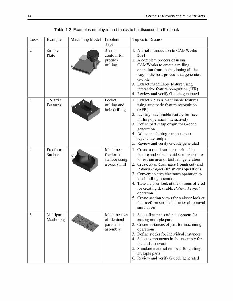
Table 1.2 Examples employed and topics to be discussed in this book Lesson Example Machining Model Problem
Type Topics to Discuss
2 Simple Plate
3-axis contour (or profile) milling
1. A brief introduction to CAMWorks 2021
2. A complete process of using CAMWorks to create a milling operation from the beginning all the way to the post process that generates G-code
3. Extract machinable feature using interactive feature recognition (IFR)
4. Review and verify G-code generated 3 2.5 Axis
Features
Pocket milling and hole drilling
1. Extract 2.5 axis machinable features using automatic feature recognition (AFR)
2. Identify machinable feature for face milling operation interactively
3. Define part setup origin for G-code generation
4. Adjust machining parameters to regenerate toolpath
5. Review and verify G-code generated 4 Freeform
Surface
Machine a freeform surface using a 3-axis mill
1. Create a multi surface machinable feature and select avoid surface feature to restrain area of toolpath generation
2. Create Area Clearance (rough cut) and Pattern Project (finish cut) operations
3. Convert an area clearance operation to local milling operation
4. Take a closer look at the options offered for creating desirable Pattern Project operation
5. Create section views for a closer look at the freeform surface in material removal simulation
5 Multipart Machining
Machine a set of identical parts in an assembly
1. Select fixture coordinate system for cutting multiple parts
2. Create instances of part for machining operations
3. Define stocks for individual instances 4. Select components in the assembly for
the tools to avoid 5. Simulate material removal for cutting
multiple parts 6. Review and verify G-code generated
Lesson 1: Introduction to CAMWorks 15
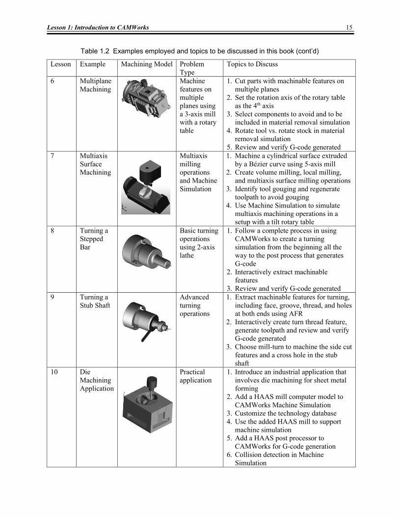
Table 1.2 Examples employed and topics to be discussed in this book (cont’d)
Lesson Example Machining Model Problem Type
Topics to Discuss
6 Multiplane Machining
Machine features on multiple planes using a 3-axis mill with a rotary table
1. Cut parts with machinable features on multiple planes
2. Set the rotation axis of the rotary table as the 4th axis
3. Select components to avoid and to be included in material removal simulation
4. Rotate tool vs. rotate stock in material removal simulation
5. Review and verify G-code generated 7 Multiaxis
Surface Machining
Multiaxis milling operations and Machine Simulation
1. Machine a cylindrical surface extruded by a Bézier curve using 5-axis mill
2. Create volume milling, local milling, and multiaxis surface milling operations
3. Identify tool gouging and regenerate toolpath to avoid gouging
4. Use Machine Simulation to simulate multiaxis machining operations in a setup with a tilt rotary table
8 Turning a Stepped Bar
Basic turning operations using 2-axis lathe
1. Follow a complete process in using CAMWorks to create a turning simulation from the beginning all the way to the post process that generates G-code
2. Interactively extract machinable features
3. Review and verify G-code generated 9 Turning a
Stub Shaft
Advanced turning operations
1. Extract machinable features for turning, including face, groove, thread, and holes at both ends using AFR
2. Interactively create turn thread feature, generate toolpath and review and verify G-code generated
3. Choose mill-turn to machine the side cut features and a cross hole in the stub shaft
10 Die Machining Application
Practical application
1. Introduce an industrial application that involves die machining for sheet metal forming
2. Add a HAAS mill computer model to CAMWorks Machine Simulation
3. Customize the technology database 4. Use the added HAAS mill to support
machine simulation 5. Add a HAAS post processor to
CAMWorks for G-code generation 6. Collision detection in Machine
Simulation

16 Lesson 1: Introduction to CAMWorks
Notes: