week 10: design for manufacturing: cnc machining
TRANSCRIPT

Week 10: Design for Manufacturing: CNC
Machining
Concepts
● Using the Hole Tool
● Using FeatureScript for spur gears
● Importing Solidworks Pack/Go files
● Direct editing an existing part (modify fillet, delete/move/replace
face)
● An introduction to the Onshape App Store (through a look at a
CAM app)
Models ● Chopper - Drivetrain completed
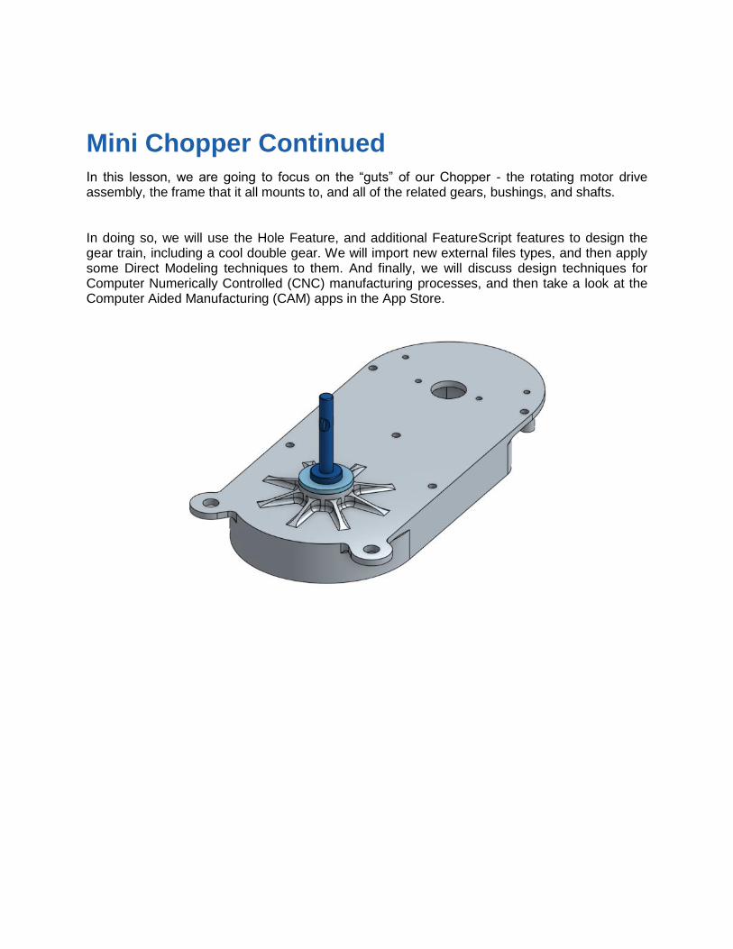
Mini Chopper Continued In this lesson, we are going to focus on the “guts” of our Chopper - the rotating motor drive assembly, the frame that it all mounts to, and all of the related gears, bushings, and shafts.
In doing so, we will use the Hole Feature, and additional FeatureScript features to design the gear train, including a cool double gear. We will import new external files types, and then apply some Direct Modeling techniques to them. And finally, we will discuss design techniques for Computer Numerically Controlled (CNC) manufacturing processes, and then take a look at the Computer Aided Manufacturing (CAM) apps in the App Store.

Design Intent Check: We’re going to start by making a Drivetrain Frame, highlighted below. The Drivetrain Frame houses the gears and hooks onto the Main Body. In the steps that follow, notice how we reference the Main Body when creating the Drivetrain Frame.
1. Start by creating a new sketch (rename it “Drivetrain Layout”) on the inside surface of the Main Body (highlighted in orange). The sketch is shown here twice, in the “Bottom” orientation; with and without the Main Body. Note the (blue) references between the screw bosses on the Main Body, and the circles in the sketch. Also note the use of a construction line, and symmetry:

2. Next, extrude out a new part, called Drivetrain Frame, away from the Main Body:

3. Next, create a new sketch, called “Drivetrain Top Sketch” on top of the new Drivetrain Frame part (the new face created by the extrude, not the same plane as the sketch in step 1). Note the “extra” sketch points that have been added to the construction line, and located at the center of the frame holes. Here it is viewed in the “Bottom” orientation:

4. Next, extrude it away from the Main Body:
5. Next, using our drivetrain sketch as a reference, create two bosses on the right side of our Frame:

6. Next, create a new sketch on top of these bosses, and locate two sketch points, , at the center:
Hole Feature Holes are unique features in that they usually have a pretty standard geometry: a cylinder, with either a chamfer (countersink), or another cylinder (counterbore) at the end of it. In addition, in

manufacturing, there are only a few ways to make a hole, and by far the most popular method is to use a drill. The cheapest way to make a hole is to use a standard size, as the tooling will already be in the machine shop. As a result, Onshape has a special Hole Feature which has a pre-populated library of standard hole sizes, and standard options such as drilled or tapped. By far, the quickest way to create a countersunk ⅜” blind threaded hole is to use the Hole Feature. There are hundreds of combinations of holes available within the Hole Feature, we will only go through one here, but more information can be found in the help: https://cad.onshape.com/help/#hole.htm
7. Using the Hole Feature, , create two holes in the center of these bosses:
Pro Tip: If you look closely, you’ll notice that even though we specified a threaded hole, no actual threads were created. This is standard practice in CAD software, because the extra detail of that geometry is not worth the value it adds to the model (we call this extra detail “computational overhead”). In other words, the CAD application, your internet connection, and your graphics card will all be asked to do a lot more work, however the detail of the thread geometry is just not necessary for creating engineering drawings, so it is not included.
8. Next, again using the Drivetrain Layout sketch as a reference, create another boss in the middle of the part:

9. Next, we’ll focus on the other side of the Drivetrain Frame, and design the geometry to hold the rotating shaft in place. Start by creating a new sketch:
10. Next, extrude this sketch upwards, towards the Main Body. This extruded part will connect to the shaft of the blade:

11. Next, we’ll create the rib profile. Create the following sketch on the Front Plane and rename it “Rib Profile”. The short edge of the triangle should be located at the center of the previous extrude:
12. Next extrude this rib profile outwards symmetrically about the Front plane:

13. Pattern the ribs around the center of the boss/hole, using the short edge of the recently sketched triangle):

14. Now, using the original Drivetrain Layout sketch let’s “clean out” the inside of the hole:

Pro Tip: The phrase “clean out” used above refers to our method of purposefully sketching and patterning the rib in the hole, and then removing the material with a subsequent feature. In some cases, this method is quicker than creating a more complicated rib profile sketch to avoid adding material to the hole. Onshape makes “cleaning up” holes like this easy because the original sketch region for the hole can just be referenced directly.
15. Next, using a previously sketched circle from the original Drivetrain Layout sketch, create a new part in the center hole. Rename the part “Pin”:
16. Next, add a fillet to the following edges. Note the use of an expression in the numerical field:

Pro Tip: There’s a very specific reason why we used an expression here. As a designer, we typically think of cylinders in regards to their diameter. In designing this part to be CNC machined, we want the machinist to use a ¼” (0.25) diameter end mill, because it is a standard size. However, for the fillet, we need to input the radius. Instead of using a calculator (or doing it in our head) we can just type in the expression directly, and Onshape will calculate it for us!
17. Next, add another fillet to the following edges (two views are shown for clarity). Again, note the use of an expression in the numerical field:

18. Next, we’ll finish up the Drivetrain Frame by creating a chamfer on the pin hole:
Pro Tip: This chamfer has a specific name, and it is called a “lead-in” chamfer. It is located at the top of this boss, so that it is easy to press the pin in. Lead in chamfers help center pins in holes like this. Many pins even come with a lead in chamfer on them as well! Pressed in pins are actually slightly larger than the hole they are going in, so without the lead-in chamfer, it would be nearly impossible to get the pin in!
Design Intent Check: Now we’re going to be making the gears that sit in the Drivetrain Frame. How do the gears interact with the Pin? How do the gears interact with one another?

Featurescript: Spur Gears We’ve already been using FeatureScript, but this will be our first time with the Spur Gear. This is a particularly helpful FS Feature because it actually models a perfect involute tooth profile. The involute profile is needed on gear teeth to maintain the proper contact between two gears as they spin. Since many gears can easily be 3D printed, it is sometimes necessary to have the detail of each and every tooth. The Spur Gear makes creating this geometry very easy.
19. Next, add the FeatureScript Spur Gear feature to the toolbar by selecting the “add
custom features” icon, :

20. Next, using the Spur Gear Feature, create the following Spur Gear, and name the new part Gear 1. Pay close attention to the settings in the dialog box below. Note the origin position is referencing the sketch point (vertex) of our Drivetrain Top Sketch:

21. Next, let’s create another gear using the next sketch point on our construction line within the Drivetrain Top sketch:

22. Next, create a new sketch on top of the smaller gear, and put a single sketch point at the center of the gear:
Pro Tip: If you observe closely, the gears are not perfectly meshed. This is not a big deal, since that is not critical in order for us to animate them and simulate the gear ratio. However, if it is critical to have the CAD data perfectly reflect a meshed gear, or you want to create the perfect animation, the “Offset Tooth angle” option in the Spur gear dialog box may be used. Below our smaller gear needed to be offset by ((1/48) * 360°)/2 or 3.75°:

23. Next, create another gear on top of the small gear, using the newly sketched point as a reference:
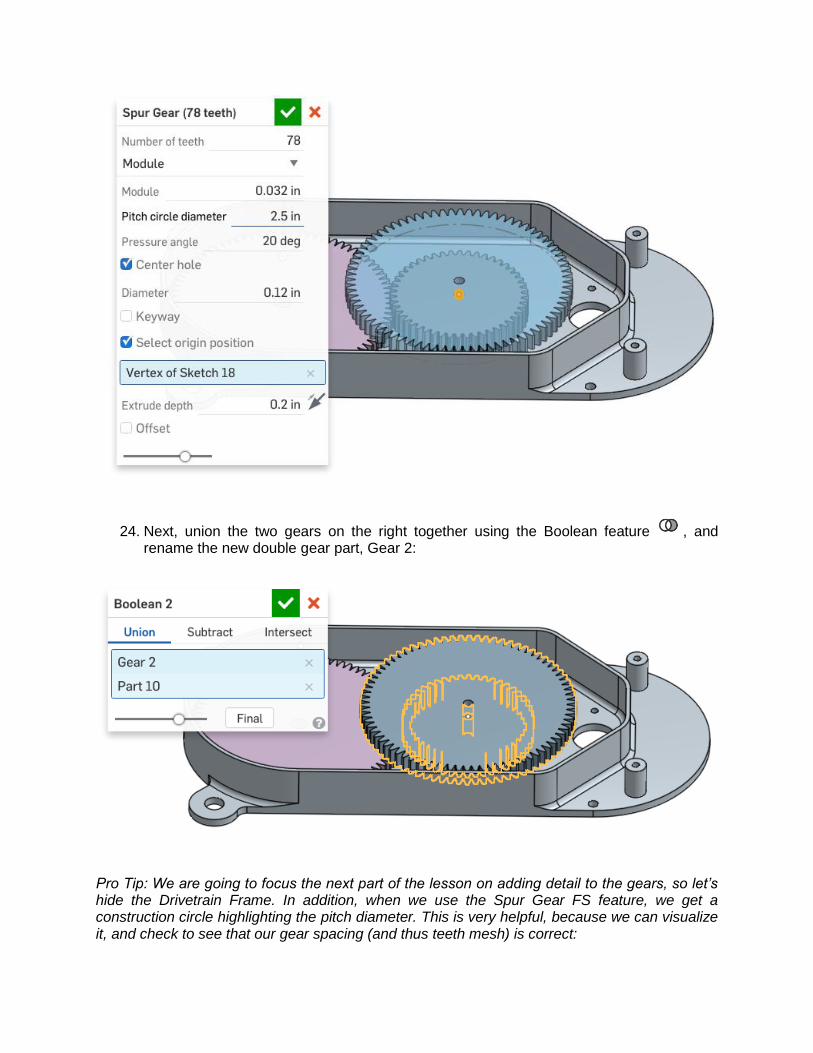
24. Next, union the two gears on the right together using the Boolean feature , and rename the new double gear part, Gear 2:
Pro Tip: We are going to focus the next part of the lesson on adding detail to the gears, so let’s hide the Drivetrain Frame. In addition, when we use the Spur Gear FS feature, we get a construction circle highlighting the pitch diameter. This is very helpful, because we can visualize it, and check to see that our gear spacing (and thus teeth mesh) is correct:
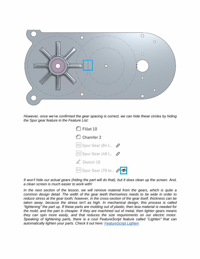
However, once we’ve confirmed the gear spacing is correct, we can hide these circles by hiding the Spur gear feature in the Feature List:
It won’t hide our actual gears (hiding the part will do that), but it does clean up the screen. And, a clean screen is much easier to work with!
In the next section of the lesson, we will remove material from the gears, which is quite a common design detail. The width of the gear teeth themselves needs to be wide in order to reduce stress at the gear tooth; however, in the cross-section of the gear itself, thickness can be taken away, because the stress isn’t as high. In mechanical design, this process is called “lightening” the part up. If these parts are molding out of plastic, then less material is needed for the mold, and the part is cheaper. If they are machined out of metal, then lighter gears means they can spin more easily, and that reduces the size requirements on our electric motor. Speaking of lightening parts, there is a cool FeatureScript feature called “Lighten” that can automatically lighten your parts. Check it out here: FeatureScript Lighten

25. Create the following sketch on the bottom of the double gear:
26. Next, remove material from the gear:
27. Next create another sketch on the double gear:

28. Next, extrude this sketch up to the face of the mounting boss on the Drivetrain Frame. Here is a cross-section with the Drivetrain Frame shown for clarity:
Pro Tip: Another way to make this selection is using Onshape’s “Select other” option in the in- context menu. First, make the parts translucent (so we can see the surface we need), right-click on the surface, and select “Select other…”:

Next, scroll down and find the surface you want, then select it. It will then highlight, and is now selected:

As designs get more complex, the “Select other” option may save you a lot of time hiding/sectioning the model!
29. Next, create a new sketch on the other side of the double gear...:

30. … and use it to remove material from the gear:
31. Next, create a new sketch on the double gear, which references the small boss on the opposite side...:

32. … and extrude that up:
33. Next, sketch a circle on the Gear 1...:

34. … and remove material from the gear:
35. Next, sketch another circle on gear 1…:

36. … and extrude out a boss:
37. Next, we’ll design a rib on Gear 1, by creating the following sketch on the Front Plane. The construction line was created using the “Use/Project” tool, and selecting the outer face of the previously extruded boss. Also, note the vertical line in the middle of the gear:

38. Next, extrude the rib symmetrically about the Front Plane:
39. Next, pattern the Rib around the gear, using the vertical line from our rib profile sketch:

40. Next, sketch another circle on back side of Gear 1, referencing the extrude from the opposite side...:
41. … and remove material:
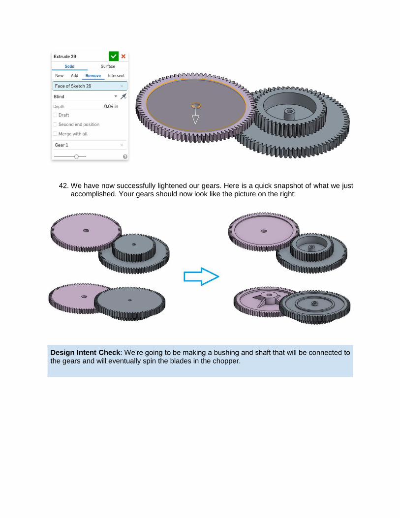
42. We have now successfully lightened our gears. Here is a quick snapshot of what we just accomplished. Your gears should now look like the picture on the right:
Design Intent Check: We’re going to be making a bushing and shaft that will be connected to the gears and will eventually spin the blades in the chopper.

43. Next, we are going to create a bushing inside of the Drivetrain Frame for the pink gear to pivot on. Start by creating the following sketch on the Front Plane. Utilize the use/project feature, and reference the Drivetrain Frame as needed so only two dimensions are required to get a fully constrained sketch:
44. Next, revolve the profile around, to create a new part, called “Bushing”:

45. Next, create another sketch on the Front Plane, utilizing Use/Project to get the bottom part of the profile. Note: both smaller diameters are the same:
46. Revolve the profile round to create a new part, called “Shaft”:

47. Next, we’ll create a stamped “clocking” feature on the shaft. Start by creating the following sketch on the Front Plane:
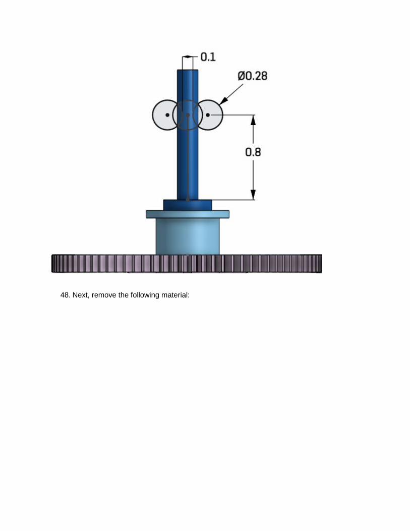
48. Next, remove the following material:

49. And use the same sketch to add a a bit more material back in:

50. Lastly, we’ll wrap up the Drivetrain by adding several chamfers to our turned parts:
Pro Tip: When designing for a Turning operation, it is quite common to include chamfers on the outer edges as we just accomplished. This is virtually free (it doesn’t add any real measureable

time to the machining process) and it removes the sharp 90 degree edges from the part. Since features like these are not very critical, they should be added at the very end of the Feature Tree, or, in the case of a multi-part Part Studio like this, after all of the “important” design features, like the profile of the Shaft and Pin parts. The final parts should now look like this:
Importing More File Types As discussed earlier, Onshape can import numerous file types (full list here: https://cad.onshape.com/help/#translation.htm) including the Solidworks “Pack n Go” zip files. This is a single zip file that usually contains an assembly, and all of the parts needed to build the assembly. This is a popular way to share Solidworks files or use them in your own designs, especially if they are coming from a partner or supplier.
51. Create a new tab within the document by importing the electric_motor.zip Solidworks Pack n Go file. Make sure to select the option to “Import file to Part Studios only (flatten)”:

Pro Tip: The “Pack n Go” zip file must be the same filename as the “top level assembly” within the zip file. This is done automatically by Solidworks, but sometimes the zip file is renamed. Double checking this will avoid errors during import.
Design Intent Check: Why are we importing a motor? The motor will have a gear in its shaft, which will move the two gears we made earlier.
52. There should be two news tabs: the original zip file and the newly converted Part Studio. Let’s navigate to the new Part Studio:

53. Notice there are 7 parts in the Parts List and 1 feature in the Feature List (“Import 1”, in addition to the default features). We would like to have a single Motor part, as this will make it easy to work with in our Chopper Assembly. To do that, we’ll need to ultimately use the Boolean union tool, but first we need to clean up the geometry. First, let’s delete Part 4 and Part 5, as they are unnecessary parts that came in from Solidworks:

Direct Editing If you recall from earlier, when we have a fully parametric CAD model, we can edit and update every feature and dimension. This allows for quick, intelligent design changes with predictable behavior. Direct Editing features allow us to directly manipulate existing CAD geometry, without having a “parametric” feature list. It is an important part of CAD modeling, because it allows us to easily modify imported geometry without having to create a bunch of new features.
In Onshape there are 4 Direct Editing Features located in the Toolbar. From left to right, they are Modify Fillet, Delete Face, Move Face, and Replace Face:

We will use a few of them as we clean up our Electric Motor part, but to learn more, see the following help files, as well as this video: https://cad.onshape.com/help/#directedit_video.htm
Modify Fillet: https://cad.onshape.com/help/#modifyfillet.htm
Delete Face: https://cad.onshape.com/help/#deleteface.htm
Move Face: https://cad.onshape.com/help/#moveface.htm
Replace Face: https://cad.onshape.com/help/#replaceface.htm
54. Sometimes, Boolean features won’t work properly if two parts are touching along an edge. In the case of our electric motor, the edge of our Tab parts (shown in red) is right along the edge of our Motor Cap part (shown in black). The Motor Cap has been made transparent for clarity:
55. Using the Move Face tool , translate the tab surface (highlighted in orange) upwards an arbitrary amount to create an interference. Make sure to include both tabs at the same time:

56. Next, Union all of the parts together to create a single part, and rename it “Drive Motor”:

Design Intent Check: Now we’re going to be making changes to our Motor. We’ll be moving some faces and modifying some fillets.

57. We suddenly learn that this Electric Motor is not exactly the one we will use. The one we will use has a slightly longer body on it. Instead of spending a lot of time sourcing new CAD geometry, we’ll just modify ours in Onshape. Use the Move Face feature to bring the front face closer to the end of the shaft. To make sure we keep the mounting holes the same, make sure to include the interior face as well. A section view is also shown for reference:

Here’s a section view comparison for clarity:

Pro Tip: When trying to figure out what faces to select, think about it this way: “What faces of my part do I expect to move?” It’s easy to forget to select the interiors of holes (both the back and and the cylindrical face), but they are important to include!
58. Next, update the radius on the Electric Motor Frame to be larger by using the Modify
Fillet tool . Again, make sure to include the interior surface, as highlighted in the picture below. A section view is shown for clarity:
59. Finally, the Electric Motor we will use for our design comes with a gear already installed. First create a new sketch on the end of the motor shaft, and place a single sketch point in the center of the shaft:

60. Next, create a new gear, called Motor Gear, at this point, using the Spur Gear Feature:
Pro Tip: Often, as a designer, we are constrained by other decisions made within the organization. An example of this is when the style/size of Electric Motor is chosen by production or even the customer. As a designer, we always need to be ready, willing, and able to adapt to changes on the fly! The direct editing features make it very easy to make changes to our imported CAD data.

The Onshape App Store Onshape is designed to be a design platform for designers all over the world. The core
functionality of the platform is, of course, creating geometry inside of a Part Studio, Assembling
it in an Assembly Studio, and creating Engineering Drawings. However, the design process is
much more complex than that, often times including additional design, analysis, documentation,
and prototyping. For these additional functions, Onshape has created a “first of its kind” App
store to be used in conjunction with Onshape CAD.
The Onshape App store has a broad offering of apps for simulation, such as Finite Element
Analysis (FEA) and Computational Fluid Dynamics (CFD), Rendering, 3D Printing and
Computer Aided Manufacturing (CAM) for Computer Numerically Controlled (CNC) machining.
The capabilities are practically endless; however, this lesson will not go through how to use
these apps in detail, so we urge you to learn more at https://appstore.onshape.com/.
App Store: CAM programs Computer Aided Manufacturing (CAM) is a broad term that basically describes any method for fabricating a part that includes a computer. This includes, but is not limited to: 3D printing, CNC Machining (i.e. Milling & Turning), Laser Cutting/Water Jetting, and Robotic Assembly processes.
In this lesson, we have been designing our Drivetrain Frame specifically to be CNC machined. In doing so, we made sure to add necessary features, such as radii and chamfers, to facilitate this process. Onshape’s App store has numerous CAM (CNC and 3D printing related) Apps that can take the CAD geometry and prepare it for the CNC machining process.
For example, here is a screenshot of our Drivetrain Frame ready for machining, where you can see the “toolpaths” - the path that the CNC milling machine would take is it machined our design out of a single piece of metal:

We’ll be using a different application on the App Store in the later weeks of the curriculum!
Congratulations! We have now successfully designed the ”guts” of our Mini Chopper! In this lesson, we did some real “heads up” designing as we thought about how our parts could be machined. We also saw some of the tools Onshape has built into FeatureScript and the App

store to help us create the detail we need and prepare for manufacturing, whether we’re making one or one thousand. Now that we have completed the lesson, let’s create a Version called “V2”. Our Chopper design should now look like this:

Summary Let’s take a second to reflect what we learned in this lesson.
1. We learned how to use the Hole feature. 2. We imported a Solidworks file. 3. We performed direct editing on an imported model, such as Move Face and Modify Fillet. 4. We were introduced to the Onshape App Store and saw an example of the available
CAM tools.
Next week, we’re going to finish making all the parts that make up the Chopper.