web viewthis application form (version 1.2) outlines the information eirgrid requires to progress an...
TRANSCRIPT

Demand Customer Connection
Connection Application Form to the Transmission System
January 2017

IntroductionThis application form (version 1.2) outlines the information EirGrid requires to progress an application for connection to the Transmission System. EirGrid recommends that the applicant refers to the customers section of the website www.eirgridgroup.com for further information on the application process. The website has links to other relevant documents such as the Grid Code. It should be noted that it is the applicant’s responsibility to comply with the technical, design and operational standards detailed in the Grid Code.
Please note for the purpose of this application form TSO should be interpreted as: the holder of the license to operate Ireland’s Transmission System (EirGrid).
Please note that this application form deals with HV connections only (≥ 110 kV) and that if an MV (≤110 kV) supply is required the applicant should first contact ESB Networks:Tel: +353 850 372 757, www.esb.ie
EirGrid reserves the right to request additional data if necessary and the applicant should provide such information promptly during and post the offer process.
It is EirGrid’s responsibility to determine the transmission connection method. If the applicant has a specific request this will be considered and examined in the process. The selected method will be based on the overall least cost technically acceptable solution unless the Applicant requests otherwise or EirGrid requires an alternative method for system reasons.
Definitions of terms used in this form can be found in the Glossary of the Grid Code.
Please note that payment of application fees can only be made via electronic fund transfer into the following account. Cheques are not accepted.
Bank Details: Sort Code: 99-02-12Barclays Bank Ireland Plc Account Name: EirGrid No 2 Account2 Park Place, Account Number: 42890602Hatch Street Swift Code: BARCIE2DDublin 2 IBAN: IE80BARC99021242890602 D02 NP94
Demand Customer Connection – Application Form • January 2017

When the application form is completed please send the form to the below address, or email to [email protected]
EirGrid Plc.Customer RelationsThe Oval,160 Shelbourne Road,Ballsbridge,Dublin 4,D04 FW28Ireland.
If any queries arise please do not hesitate to contact our Customer Relations Team at:
Tel: ++353 1 237 0472Email: [email protected]
Demand Customer Connection – Application Form • January 2017

Details of Applicant 1. Full name of the applicant.
2. Address of the applicant or in the case of a corporate body, the registered address (including Eircode) and company registration number.
Company Registration no. (If applicable)
3. Telephone Number
4. Contact Person(s)
5. Email Address
6. a) Please confirm the Contact Address for all written correspondence (if different from above)
b) Please confirm the Customer Name, Address and Contact Details to be used on invoices for billing purposes
7. Please nominate a preferred name for this facility.EirGrid will take this preferred name into consideration when determining the facility’s station name but reserves the right to change it in order to avoid any potential for confusion with other projects or stations.
Demand Customer Connection – Application Form • January 2017

Please refer to Appendix A for EirGrid’s policy on User Site/Station Naming.
8. Please specify the address of this facility.
9. Please confirm if you have achieved planning permission for the facility.
Yes No If yes, please confirm the planning authority reference.
If no, please confirm when you expect to achieve it. If the date of application is dependent on the connection offer date, please confirm the expected number of months to achieve planning permission for the facility.
Months
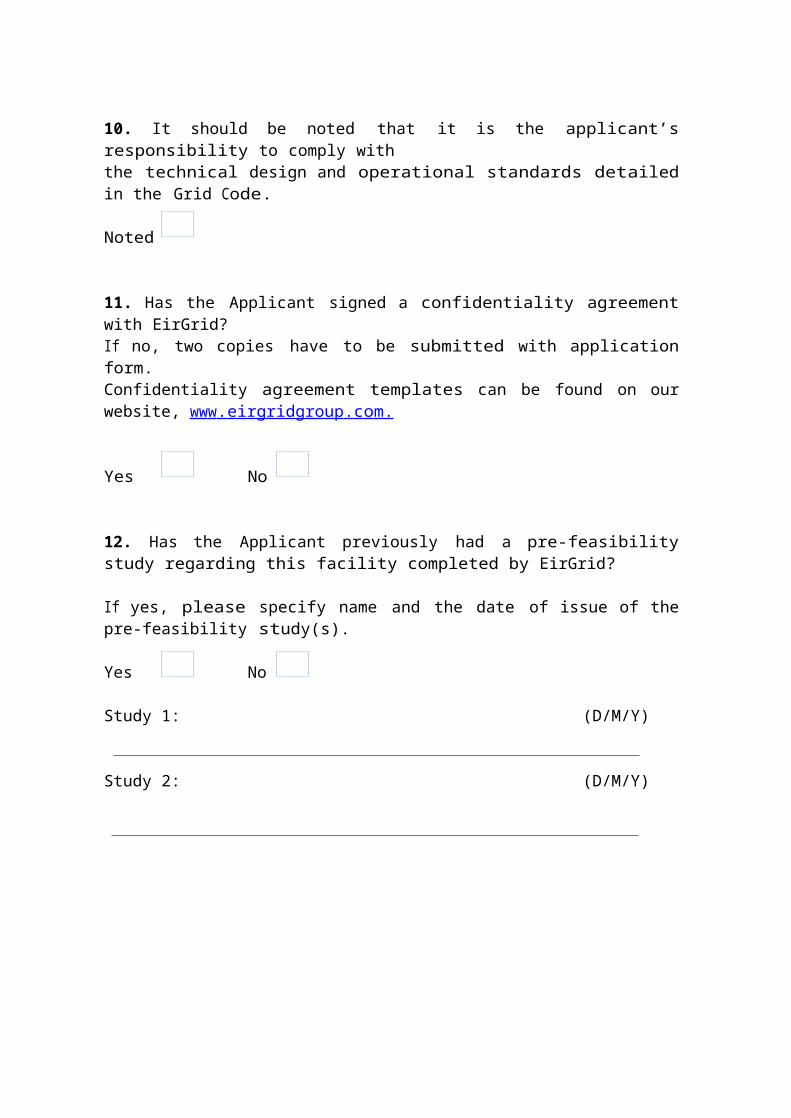
10. It should be noted that it is the applicant’s responsibility to comply withthe technical design and operational standards detailed in the Grid Code.
Noted
11. Has the Applicant signed a confidentiality agreement with EirGrid?If no, two copies have to be submitted with application form.Confidentiality agreement templates can be found on our website, ww w . eirgridgroup . c o m.
Yes No
12. Has the Applicant previously had a pre-feasibility study regarding this facility completed by EirGrid?
If yes, please specify name and the date of issue of the pre-feasibility study(s).
Yes No
Study 1: (D/M/Y)
Demand Customer Connection – Application Form • January 2017

Study 2: (D/M/Y)
Customer Type
13. Please state which of the following demand types applies to this application. Then fill in the relevant sections/questions which apply to that type as specified below:
A. New transmission customer, fill in questions 18– 44.
B. Existing transmission customer with transformer changes, fill in questions 15 – 44.
C. Existing transmission customer (no transformer changes), fill in questions 15 –26 and 35 - 44.
14. State if the applicant currently has a connection at the distribution level.
Yes No If yes, please continue with question 15.If no, proceed to question 18.
Technical Information
15. What is your existing connection point? (Please specify substation/location)
16. What is your current Maximum Import Capacity (MIC)?
MIC (MVA)
17. Please explain if your intentions are to transfer this demand to your new transmission connection and if this existing demand is included in your new transmission MIC.
Demand Customer Connection – Application Form • January 2017
18. New Maximum Import Capacity (MIC). This is the amount of importing transmission capacity that will be provided in the connection offer. (New MIC to include existing contracted MIC).
MIC (MVA)19. Based on question 17 please state the following:
Active Power P MW
Reactive Power Q MVAr
20. Please provide details of ramp schedule (power consumption over time) the facility intends to implement. Provide graph if necessary.
The ramping schedule will need to be compliant with the rule set included in the MIC Administration Paper. Available to view at:http://www.eirgridgroup.com/site-files/library/EirGrid/MIC-administration-paper-v2-0-updated-14-April-2015.pdf
EirGrid will allow up to 3 steps/ramps in the ramping schedule. Please note any change to the requested ramping schedule during the offer process may cause delays to the offer processing time and therefore the initial ramping schedule submitted should be the customer’s best available information.
21. Target Connection Date (this date will be used for connection assessment).(D/M/Y)
22. State the number of connecting circuits to the Transmission System (e.g. one, two etc.), the applicant requires for technical and/or security reasons.
Please also state any specific connection method requests e.g. the use of underground cabling or connection to a specific station etc.
Demand Customer Connection – Application Form • January 2017

Please note that while underground cabling may be quicker to build than overhead line however it is more expensive and in certain areas of the country the use of underground cabling can have impacts on the Transmission System, for example amplification of background harmonic distortion, that would require additional equipment to be installed to mitigate their impact.
Where the possibility of harmonic amplification exists more detailed studies are required during the process leading to the issuance of a Connection Offer which may not be possible to complete within the standard 90 business day timeframe. Please also note that customers pay for 50% of the least cost connection method. Customer requested connection methods above and beyond the least cost connection method are fully chargeable to customers. Further information on this aspect of charging policy is available at:http://www.eirgridgroup.com/customer-and-industry/general-customer-information/connections-and-contracts/
23. Confirm whether you wish the connection offer to issue on a contested or a non-contested basis and broadly outline the works the customer wishes to contest. Further information on contestability is available at:http://www.eirgridgroup.com/site-files/library/EirGrid/Contestability-and-Connection-Assets.pdf
Type of DemandThe purpose of this section is to provide EirGrid with a broad knowledge of the type of demand the customer will connect.
24. Please provide a graph of the facility’s Load Factor over 1 year.Name of Attachment:
25. Please indicate if there are any items of plant which can contribute significant levels of harmonic distortion i.e. Large variable speed drives, large inverters etc. If yes please provide a general outline.
Yes No
Name of Attachment:
Demand Customer Connection – Application Form • January 2017

26. Please indicate if your facility has any equipment that is designed to fluctuate by more than 5 MVA within a short period of time at the point of connection to the Transmission System.
If Yes, EirGrid may require further clarifications. However, these will not affect the completeness of your application.
Grid Connected Transformer Data
There are many types of transformers. This application form specifies Two Winding Transformers. All impedances should be stated in % on transformer rated MVA base.Please note that the connection voltage is determined by EirGrid in accordance with normal standards, as detailed in the Grid Code, taking into account the particulars of each development. If the connection voltage differs from that specified in the Application, EirGrid will request new data corresponding to the new voltage level. An appropriate connection voltage will initially be examined as part of the application check.Please note the Grid Connected Transformer specified must be compliant with section WFPS1.6.5 of the Grid Code.If the full details are not available at the time of application EirGrid can assume values based on the expected transformer size in MVA provided by the applicant and EirGrid would make assumptions. Please note any issues with the assumptions would be at the applicants risk and the applicant will have to provide the information requested in this section and a full manufactures test report for the installed transformer prior to energisation.
Two Winding TransformersTransformer 1 Transformer2
27. Rating of Transformer (MVA)
28. Transformer voltage ratio HV/ LV (kV)
29. Transformer positive sequence resistance (R1%)
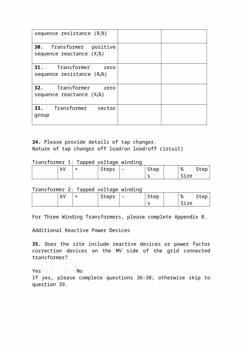
30. Transformer positive sequence reactance (X1%)
31. Transformer zero sequence resistance (R0%)
32. Transformer zero sequence
Demand Customer Connection – Application Form • January 2017

reactance (X0%)
33. Transformer vector group
34. Please provide details of tap changer. Nature of tap changer off load/on load/off circuit)
Transformer 1: Tapped voltage windingkV + Steps - Steps % Step Size
Transformer 2: Tapped voltage windingkV + Steps - Steps % Step Size
For Three Winding Transformers, please complete Appendix B.
Additional Reactive Power Devices
35. Does the site include reactive devices or power factor correction devices on the MV side of the grid connected transformer?
Yes No If yes, please complete questions 36-38; otherwise skip to question 39.
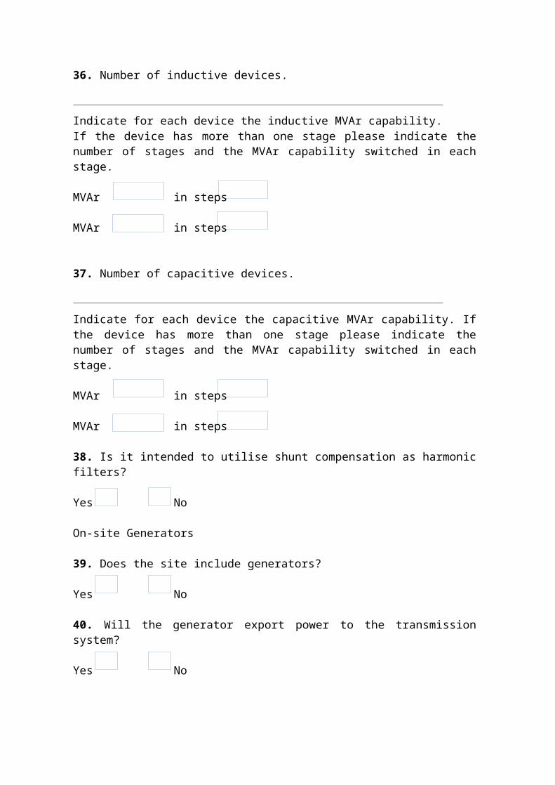
36. Number of inductive devices.
Indicate for each device the inductive MVAr capability. If the device has more than one stage please indicate the number of stages and the MVAr capability switched in each stage.
MVAr in steps
MVAr in steps
37. Number of capacitive devices.
Indicate for each device the capacitive MVAr capability. If the device has more than one stage please indicate the number of stages and the MVAr capability switched in each stage.
MVAr in steps
MVAr in steps
Demand Customer Connection – Application Form • January 2017

38. Is it intended to utilise shunt compensation as harmonic filters?
Yes No
On-site Generators
39. Does the site include generators?
Yes No
40. Will the generator export power to the transmission system?
Yes No
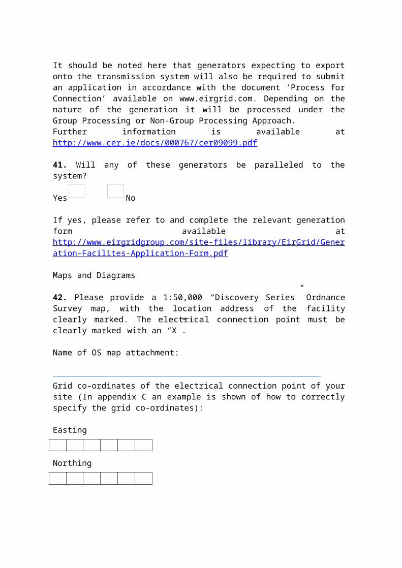
It should be noted here that generators expecting to export onto the transmission system will also be required to submit an application in accordance with the document ‘Process for Connection’ available on www.eirgrid.com. Depending on the nature of the generation it will be processed under the Group Processing or Non-Group Processing Approach. Further information is available at http://www.cer.ie/docs/000767/cer09099.pdf
41. Will any of these generators be paralleled to the system?
Yes No
If yes, please refer to and complete the relevant generation form available at http://www.eirgridgroup.com/site-files/library/EirGrid/Generation-Facilites-Application-Form.pdf
Maps and Diagrams
42. Please provide a 1:50,000 “Discovery Series” Ordnance Survey map, with the location address of the facility clearly marked. The electrical connection point must be clearly marked with an “X”.
Name of OS map attachment:
Grid co-ordinates of the electrical connection point of your site (In appendix C an example is shown of how to correctly specify the grid co-ordinates):
Easting
Northing
Demand Customer Connection – Application Form • January 2017

43. Please provide a site plan in an appropriate scale. This site plan should indicate:• the proposed location of the connection point,• generators,• transformers and• site buildings.
Note that the connection point is normally at the HV bushings of the grid connected transformer. Space for the transmission compound will have to be clearly marked on the site plan. The exact size of the compound will depend on the connection method defined in the connection offer. Site plan is to be submitted in soft copy.Site plan is to be submitted in soft copy.
Name of site plan attachment:
44. Please provide an electrical Single Line Diagram (SLD) of the proposed facility detailing all significant items of plant and their values.• Generator transformer(s),• power factor correction devices,• location of alternative connection for on-site generation (if applicable) and• grid connected transformer(s).
Name of the SLD attachment, should be submitted in soft copy.
Demand Customer Connection – Application Form • January 2017
Appendixes
Appendix A:EirGrid’s policy on Station Naming,
Station name must be unique and pronounceable for all stations, station name must be geographically accurate and descriptive, station name should be as local as possible to provide for future
proofing for other stations that may locate in the same area, station names should be identified in the following order:
- town land it is situated in,- nearby town land,- adjacent landmark, i.e. a mountain,
station names should not be named after a company, any individual supplier or manufacturer as this is liable to change,
station name must not start with the letter X as this is reserved for ETSO.
Note: Station name above applies to both the transmission station name and the users site name.
EirGrid will also assign a unique 3 character code to each generation unit which are used by various software for modelling purposes and dispatch purposes. This 3 character code is based on the user site name and the number of generators at that site.
Appendix B:
Demand Customer Connection – Application Form • January 2017
Transformer 1 HV winding LV1 winding LV2 winding
B1. Transformer rated MVAB2. Transformer rated voltage (kV)B3. Transformer vector group
Transformer 2 HV winding LV1 winding LV2 winding
B4. Transformer rated MVAB5. Transformer rated voltage (kV)B6. Transformer vector group
Clearly specify the MVA base (in space provided between brackets) which the measured impedances below are related to: Transformer 1 Transformer 2 Transformer 3B7.Transformer positive sequence resistance (R1HL1%) between HV/LV1:B8.Transformer positive sequence reactance (X1HL1%) between HV/LV1:B9. Transformer zero sequence resistance (R0HL1%) between HV/LV1:B10.Transformer zero sequence reactance (X0HL1%) between HV/LV1:B11.Transformer positive sequence resistance (R1HL2%) between HV/LV2:B12.Transformer positive sequence reactance (X1HL2%) between HV/LV2:B13.Transformer zero sequence resistance (R0HL2%) between HV/LV2:B14.Transformer zero sequence reactance (X0HL2%) between HV/LV2:B15.Transformer positive sequence resistance (R1L1L2%) between LV1/LV2:B16. Transformer positive sequence reactance (X1L1L2%) between LV1/LV2:
Demand Customer Connection – Application Form • January 2017
B17. Transformer zero sequence resistance (R0L1L2%) between LV1/LV2:B18. Transformer zero sequence reactance (X0L1L2%) between LV1/LV2:B19. Transformer positive sequence resistance (R1HL1L2
%) between HV/(LV1+LV2):B20. Transformer positive sequence reactance (X1HL1L2%) between HV/(LV1+LV2):
Demand Customer Connection – Application Form • January 2017

Appendix C:Grid co-ordinatesHow to define the grid co-ordinates from “Discovery Series” ordinance survey map.
Easting and Northing co-ordinates should be stated to six places. Easting co-ordinates are the numbers on the horizontal axis. Northing co-ordinates are the numbers on the vertical axis.
Figure 1: Example OS Map with 'X' clearly marking location of a facility.
Demand Customer Connection – Application Form • January 2017

Appendix D:Checklist
Application form completed in full, application fee, two signed copies of confidentiality agreement (if applicable), OS map, single line diagram (S LD), soft copy, ramp schedule, load factor graph for 1 year, details provided of equipment that contributes significant levels of harmonic
distortion (if applicable) and appendix relevant.
Demand Customer Connection – Application Form • January 2017