generation facilities - eirgrid group
TRANSCRIPT

Generation Facilities Connection Application Form to the
Transmission System
September 2020

Generation Facilities – Application Form • September 2020
Page 2
Introduction This application form outlines the information EirGrid requires to progress an application for connection to the Transmission System. EirGrid recommends that the applicant refers to the customers section of the website www.eirgrid.com for further information on the application process. The website has links to other relevant documents such as the Grid Code. It should be noted that it is the applicant’s responsibility to comply with the technical, design and operational standards detailed in the Grid Code. Please note for the purpose of this application form TSO should be interpreted as: the holder of the license to operate Ireland’s Transmission System (EirGrid). Please note that this application form deals with HV connections only (≥ 110 kV) and that if an MV (≤ 110 kV) supply is required the applicant should first contact ESB Networks: Tel: +353 850 372 757, www.esb.ie EirGrid reserves the right to request additional data if necessary and the applicant should provide such information promptly during and post the offer process. It is EirGrid’s responsibility to determine the transmission connection method. If the applicant has a specific request this will be considered and examined in the process. The selected method will be based on the overall least cost technically acceptable solution unless the applicant requests otherwise or EirGrid requires an alternative method for system reasons. Definitions of terms used in this form can be found in the Glossary of the Grid Code. The following information will be disclosed in the applications list found in the ‘Completed Generation Applications’ section on www.eirgrid.com once the application is deemed fully complete by EirGrid:
project name,
applicant details (contact name, email address, telephone number),
received complete date,
status of application,
grid co-ordinates of electrical connection point,
capacity of project (MW),
assigned transmission station, and
generation type. Please note that if the application is not initially deemed complete, then the received complete1 date is recorded as the date that all necessary information has been provided to the system operator. Please note that payment of application fees can only be made via electronic fund transfer into the following account. Cheques are not accepted.
1 More information on the Received Complete Date is available at:
http://gridshare/sites/FG/CPC/CPC%20Policy%20Documentation%20Project/Basis%20for%20calculating%20%20Received%20Complete%20Date%20-%20FINAL.pdf

Generation Facilities – Application Form • September 2020
Page 3
Bank Details: Sort Code: 99-02-12 Barclays Bank Ireland Plc Account Name: EirGrid No 2 Account 2 Park Place, Account Number: 42890602 Hatch Street Swift Code: BARCIE2D Dublin 2 D02 NP94 IBAN: IE80BARC99021242890602 When the application form is completed please send the form to the below address, or email to [email protected] EirGrid Tel: +353 1 23 70472 Customer Relations Fax: +353 1 661 5375 The Oval, 160 Shelbourne Road, Ballsbridge, Dublin 4, D04 FW28 Ireland.
For the avoidance of doubt:
Section 1 applies to all applicants
Section 2 applies to all applicants
Section 3 A applies to renewable and inverter based generation e.g. wind, solar, batteries etc.
Section 3 B applies to conventional generation
Section 4 applies to all applicants
Section 5 applies to applilcants seeking DS3 prioritisation under CRU/18/058
Section 6 applies to all applicants. Please Note: Information contained within this application form may need to be shared with the Distribution System Operator in order to sufficiently assess the application.

Generation Facilities – Application Form • September 2020
Page 4
1. Details of Applicant
Yes No
1. Full name of the applicant. 2. Address of the applicant or in the case of a corporate body, the registered address and company registration number. Company Registration No. (If applicable) 3. Telephone Number 4. Contact Person(s) 5. Email Address 6. Contact Address (if different)

Generation Facilities – Application Form • September 2020
Page 5
7. Please nominate a preferred name for the facility. Please Note: The TSO will take this preferred name into consideration when determining the facilities’ station name but reserves the right to change it in order to avoid any potential for confusion with other projects or stations. Please refer to Appendix A for EirGrid’s policy on User Site/Station Naming. 8. Please specify the address of the facility. 9. Please confirm if you have achieved planning permission2 for the facility. Yes No Please refer to Section 6 of this application form for inputting planning permission details 10. It should be noted that it is the applicant’s responsibility to comply with the technical design and operational standards detailed in the Grid Code. Noted 11. Has the applicant signed a confidentiality agreement with the TSO for this facility? Yes No If no, two copies have to be submitted with application form. Confidentiality agreement templates can be found on EirGrid’s website, www.eirgrid.com 12. Has the applicant previously had a pre-feasibility study regarding this facility completed by TSO? Yes No If yes, please specify name and the date of issue of the Pre-feasibility study(s).
2 As per CRU20/060, planning permission is a pre-requisite for applications entering ECP-2.1

Generation Facilities – Application Form • September 2020
Page 6
Study 1: (D/M/Y) Study 2: (D/M/Y)

Generation Facilities – Application Form • September 2020
Page 7
13. Please provide a 1:50,000 “Discovery Series” Ordnance Survey map, with the location address of the facility clearly marked. The electrical connection point must be clearly marked with an “X”. Name of OS map attachment: Grid co-ordinates of the electrical connection point of your site (In appendix A an example is shown of how to correctly specify the grid co-ordinates): Easting
Northing
14. Please provide a site plan in an appropriate scale. This site plan should be submitted in soft copy only and indicate:
• the site boundary, • the proposed location of the connection point, • generators, • transformers, • site buildings and • meteorological masts etc.
Note that the connection point is normally at the HV bushings of the grid connected transformer. Space for the transmission compound will have to be clearly marked on the site plan. The exact size of the compound will depend on the connection method defined in the connection offer. Name of site plan attachment. Please note that EirGrid may require an option from the applicant for additional land at the facility to facilitate future development of the Transmission System. Noted 15. Please provide an electrical Single Line Diagram (SLD) of the proposed facility in soft copy only detailing all significant items of plant and their values. • relevant voltage levels, • generator transformer(s), • power factor correction devices, • location of alternative connection for house load (if applicable) and

Generation Facilities – Application Form • September 2020
Page 8
• grid connected transformer(s). Name of the SLD attachment soft copy; 16. For applications where the below is applicable: Please provide a functional block diagram of the main plant components, showing boilers, turbines, heat recovery boilers, alternators, any heat or steam supplies to other processes etc. The functional block diagram must indicate whether single or separate shaft is to be utilised in the case of CCGT. Noted

Generation Facilities – Application Form • September 2020
Page 9
2. General Data
17. Maximum Export Capacity (MEC) required in MW. This is the amount of exporting transmission capacity that will be provided for in the connection offer and is the maximum capacity that can be exported onto the transmission system. MEC (MW) 18. State the number of connecting circuits to the Transmission System (e.g. one, two etc.) the applicant requires for technical and/or security reasons. Please also state any specific connection method requests e.g. the use of underground cabling or connection to a specific station etc. Please note that while underground cabling may be quicker to build than overhead line, however it is more expensive and in certain areas of the country the use of underground cabling can have impacts on the Transmission System. For example amplification of background harmonic distortion, that would require additional equipment to be installed to mitigate their impact. Where the possibility of harmonic amplification exists more detailed studies are required during the process leading to the issuance of a Connection Offer which may not be possible to complete within the standard 90 business day timeframe. Please also note that customers pay for 100% of the least cost connection method. Customer requested connection methods above and beyond the least cost connection method are fully chargeable to customers. Further information on this aspect of charging policy is available at: http://www.eirgridgroup.com/customer-and-industry/general-customer-information/connections-and-contracts/ 19. Confirm whether you wish the connection offer to issue on a contested or a non-contested basis and broadly outline the works the customer wishes to contest.

Generation Facilities – Application Form • September 2020
Page 10
Further information on contestability is available at: http://www.eirgridgroup.com/site-files/library/EirGrid/Contestability-and-Connection-Assets.pdf

Generation Facilities – Application Form • September 2020
Page 11
3. Section A: Inverter based Generation
Type 1 Type 2 Type 3
26. Please provide a power curve approved by the generating unit manufacturer and specific to the generating unit(s) specified above. Submitted Name of attachment: 27. Please provide a power quality test report. Submitted Name of attachment:
All impedances in % on transformer MVA base. Type 1 Type 2 Type3
20. Manufacturer of generating unit
21. Model and type generating unit
22. Number of generators of type
23. Rated power output of each generating unit (MW)
24. Generating unit rated MVA
25. Generating unit voltage (kV)
28. Rating of WTG/inverter transformer (MVA)
29. WTG/inverter transformer voltage ratio MV/LV (kV)
30. WTG/inverter transformer positive sequence resistance (R1%)

Generation Facilities – Application Form • September 2020
Page 12
35. Number of inductive devices. Indicate for each device the inductive MVAr capability. If the device has more than one stage please indicate the number of stages and the MVAr capability switched in each stage. MVAr steps MVAr steps 36. Number of capacitive devices. Indicate for each device the capacitive MVAr capability. If the device has more than one stage please indicate the number of stages and the MVAr capability switched in each stage. MVAr steps MVAr steps 37. Please indicate the MVAr contribution of the internal generation facility structure (i.e. 20 kV cable) MVAr 38. Please provide test results demonstrating fault ride through capability in accordance with Figure WFPS1.1 in the Wind Grid Code ref: WFPS1.4.1. Name of the attachment:
31. WTG/inverter transformer positive sequence reactance (X1%)
32. WTG/inverter transformer zero sequence resistance (R0%)
33. WTG/inverter transformer zero sequence reactance (X0%)
34. WTG/inverter transformer vector group

Generation Facilities – Application Form • September 2020
Page 13
39. Please describe how the generation facilitys internal network structure (collector network) will be laid out. The description should include a breakdown of how the individual turbines/inverters are connected together as well as how they are connected back to the generation facility substation. Please specify different cable sizes and individual lengths of cable. Name of internal network structure attachment: Type 1 Type 2 Type3
40. Conductor cross sectional area per core (mm2)
41. Conductor type (Al, Cu, etc.)
42. Type of insulation
43. Total length of Cable Type (km)

Generation Facilities – Application Form • September 2020
Page 14
Section B: Conventional Generation
44. Please provide details of the expected running regime. (E.g. base load, peaking etc.) Plant Capability Data Generator capabilities must comply with the Grid Code. Please review the connection conditions for a list of the required standards.
(1) Normal operating air conditions to be assumed = 10°c, 1.01bar, 70% humidity. Please note that the sum of the maximum continuous generation capacity at normal operating air conditions for the individual generators unit shall be used to record the Installed Plant (as defined in the Grid code) for the purposes of the connection offer. Grid Connected Transformer Data There are many types of transformers. This application form specifies two and three winding transformers in Appendix B. Please fill in relevant section. All impedances should be stated in % on transformer MVA base. Please note that the connection voltage is determined by EirGrid in accordance with normal standards as detailed in the Grid Code taking into account the particulars of each development. If the connection voltage differs to that specified in the Application, EirGrid will request new data corresponding to the new voltage level. An appropriate connection voltage will initially be examined as part of the application check.
Unit 1 Unit 2 Unit 3
45. Type of generation plant (hydro, combined cycle, combustion turbine, steam turbine, gas turbine etc.)
46. Primary Fuel Source
47. Secondary Fuel Source
48. Manufacturer of generator
49. Model and type of above generator
50. Type of generator (synchronous, asynchronous, etc.)
51. Number of generators of type
52. Generator voltage (kV)
53. Generator rated MVA
54. Maximum continuous generation capacity at normal operating air conditions(1) (MW).
55. Minimum continuous generating capacity (MW)

Generation Facilities – Application Form • September 2020
Page 15
4. Station Data This section applies to all applicants 56. Please specify the Maximum Import Capacity (MIC) required in MVA. This is the amount of import capacity that the site will require during start up and will be provided for in the connection offer. MIC (MVA) If the requested MIC is >1MVA please state the following: Active Power P MW Reactive Power Q MVAr 57. Please specify the House Load required for the site under normal operating conditions. MW MVAr 58. Please state if a separate transmission connection is required to supply House Load. Yes No If required please submit details. Name of attachment: 59. Plase provide a reactive capability curve: For Inverter based Generation For the site as measured at the lower voltage side of the grid connection transformer. The capability curve should specify MVAr vs MW for the entire range of MW output. The curve shold be consistent with the answers given in the questions above. For Conventional Generation For the entire active power operating range for each generator as provided at the alternator terminals and at normal operating conditions. Name of the attachment:

Generation Facilities – Application Form • September 2020
Page 16
60. Please state the power factor ranges of the generator type at the specified active power percentages of the maximum continuous export capacity and then specify the equivalent MVAr capability.
35% 100%
Ind. Cap. Ind. Cap.
Type 1 Equivalent MVAr
Type 2 Equivalent MVAr
Type 3 Equivalent MVAr
Generation Data for Fault Studies (Short Circuit) For Renewable Generation (Qu 61 – 62) 61. Please provide the following currents for each type of wind turbine generator/solar invert used in the generation facility. Type 1 Type 2 Type3
IK" – Initial symmetrical short circuit current
IP – Peak short circuit current
Ib100 – Short circuit breaking current at 100ms
Ib80 – Short circuit breaking current at 80ms
IK – Steady state short circuit current
62. Please provide a short circuit decrement curve (current vs. time) that represents each type of wind turbine generator/solar inverter used in the generation facility. Name of attachment(s): For Conventional Generation (Qu 63 – 69)
63.Xd’ – Generator Direct Axis Transient Reactance (unsaturated): (pu on machine MVA base)
64.Xd – Generator Direct Axis Transient Reactance

Generation Facilities – Application Form • September 2020
Page 17
69. Please submit the open-circuit generator magnetic saturation curve. If this data is not available at this stage EirGrid will assume the magnetic saturation characteristics for the generator to be in accordance with Appendix C. Complete tick the appropriate boxes for the following section: Please assume generator magnetic saturation curve as per Appendix C, OR Please assume other generator magnetic saturation curve. Name of attachment specifying curve:
(saturated): (pu on machine MVA base)
65.Xd’’ – Generator Sub-transient Reactance (unsaturated): (pu on machine MVA base)
66.Xd’’ – Generator Sub-transient Reactance saturated): (pu on machine MVA base)
67.X2 – Generator Negative Phase Sequence Synchronous Reactance: (pu on machine MVA base)
68.X0 – Generator Zero Phase Sequence Reactance: (pu on machine MVA base)

Generation Facilities – Application Form • September 2020
Page 18
Dynamic Simulation Data This section applies to all applicants For EirGrid to be able to carry out dynamic simulations the applicant needs to submit dynamic simulation information appropriate to their facility. Please select one of the following ways for providing the dynamic simulation data: A.The applicant can submit a soft copy of a PSSE Dynamic Model representation of the generation facility connected to a simple grid system. Please see the EirGrid website for general details on how to prepare a sample PSSE model of a connection:
OR B.The applicant can submit the specific dynamic simulation data requested in Appendix C, D, E and F or already included on the dynamic model register on the EirGrid website, whichever is applicable. Please note that exact information and parameters regarding excitation, governor systems and power system stabiliser will be required at the time of commissioning and failure to produce this may result in a delay in energisation of the facility. .

Generation Facilities – Application Form • September 2020
Page 19
5. DS3 Applicants 70. Please indicate which services can be provided FFR POR Fast Frequency Response 71. What level of FFR can be provided? FFR (MW) 72. For how many hours per year can the service be provided? 73. Service at low MW outputs Can the service be provided at 0MW output levels? Yes No Can the service be provided while operating below 20% of MEC? Yes No Primary Operating Reserve 74. What level of POR can be provided? POR (MW) 75. For how many hours per year can the service be provided? 76. Service at low MW outputs Can the service be provided at 0MW output levels? Yes No Can the service be provided while operating below 20% of MEC? Yes No

Generation Facilities – Application Form • September 2020
Page 20
6. Planning Permission Confirmation3,4 This section applies to all applicants4
Telephone_______________ Email___________________
I (Name in Block Capitals) ___________________________________,
Position: _________________________________________________,
on behalf of (Company Name in Block Capitals as specified in the Applicant
Detail of this application form)
________________________________________________________
confirm that Planning Permission for the generator units as specified in this
application form is in place as follow:
Planning Reference No: ___________________________
Planning Permission Grant Date ___________________________
Planning Reference No: ___________________________
Planning Permission Expiry Date: ___________________________
Extension applied for? YES □ NO □
OR
Confirm that Planning Permission for the generator units as specified in this
application is not required for the following reason:
Signed: ____________________ Date: ______________________
3 As per CRU20/060 if an applicant makes a false, misleading or inaccurate declaration in respect
of planning permission requirements, this will be deemed to be an “event of default” under the connection agreement. 4
As per CRU/20/060 Planning permission required to apply to ECP-2, except for community-led projects, though they will need planning permission to receive a connection offer. Planning permission is one of the prioritisation criteria in the event of over-subscription as per CRU/20/060.

Generation Facilities – Application Form • September 2020
Page 21
And I, (Name in Block Capitals), ______________________________,
Profession: ______________________________________________,
on behalf of (Company Name in Block Capitals)
________________________________________________________
warrant that I have conducted the necessary checks and am satisfied that the
aforementioned planning permission is in place if applicable.
________________________________________________________
Date: ___________________________________________________
Solicitor / Planning Consultant Address:
________________________________________________________
________________________________________________________
Solicitor5 / Planning Consultant Number6:
________________________________________________________
Solicitor / Planning Consultant Stamp:
5 As per the Law Society of Ireland (www.lawsociety.ie)
6 As per the Irish Planning Institute (www.ipi.ie) or Royal Town Planning Institute (www.rtpiconsultants.co.uk)

Generation Facilities – Application Form • September 2020
Page 22
Appendixes Appendix A EirGrid’s policy on Station Naming:
• Station name must be unique and pronounceable for all stations, • Station name must be geographically accurate and descriptive, • Station name should be as local as possible to provide for future
proofing for other stations that may locate in the same area, • Station names should be identified in the following order;
- town land it is situated in, - nearby town land, - adjacent landmark, i.e. a mountain.
• Station names should not be named after a company, any individual supplier or manufacturer as this is liable to change,
• Station name must not start with the letter X as this is reserved for ETSO.
Note: Station name above applies to both the transmission station name and the user’s site name. EirGrid will also assign a unique 3 character code to each generation unit which are used by various software for modelling purposes and dispatch purposes. This 3 character code is based on the user site name and the number of generators at that site.

Generation Facilities – Application Form • September 2020
Page 23
Appendix B All impedances should be stated in % on transformer rated MVA base. Please note that the connection voltage is determined by EirGrid in accordance with normal standards, as detailed in the Grid Code, taking into account the particulars of each development. If the connection voltage differs from that specified in this application, EirGrid will request new data corresponding to the new voltage level. An appropriate connection voltage will initially be examined as part of the application check. Two Winding Transformers Transformer 1 Transformer2
B8. Please provide details of tap changer. Nature of tap changer off load/on load/off circuit)
B1. Rating of Transformer (MVA)
B2. Transformer voltage ratio HV/ LV (kV)
B3. Transformer positive sequence resistance (R1%)
B4. Transformer positive sequence reactance (X1%)
B5. Transformer zero sequence resistance (R0%)
B6. Transformer zero sequence reactance (X0%)
B7. Transformer vector group
Generation Facilities – Application Form • September 2020
Page 24
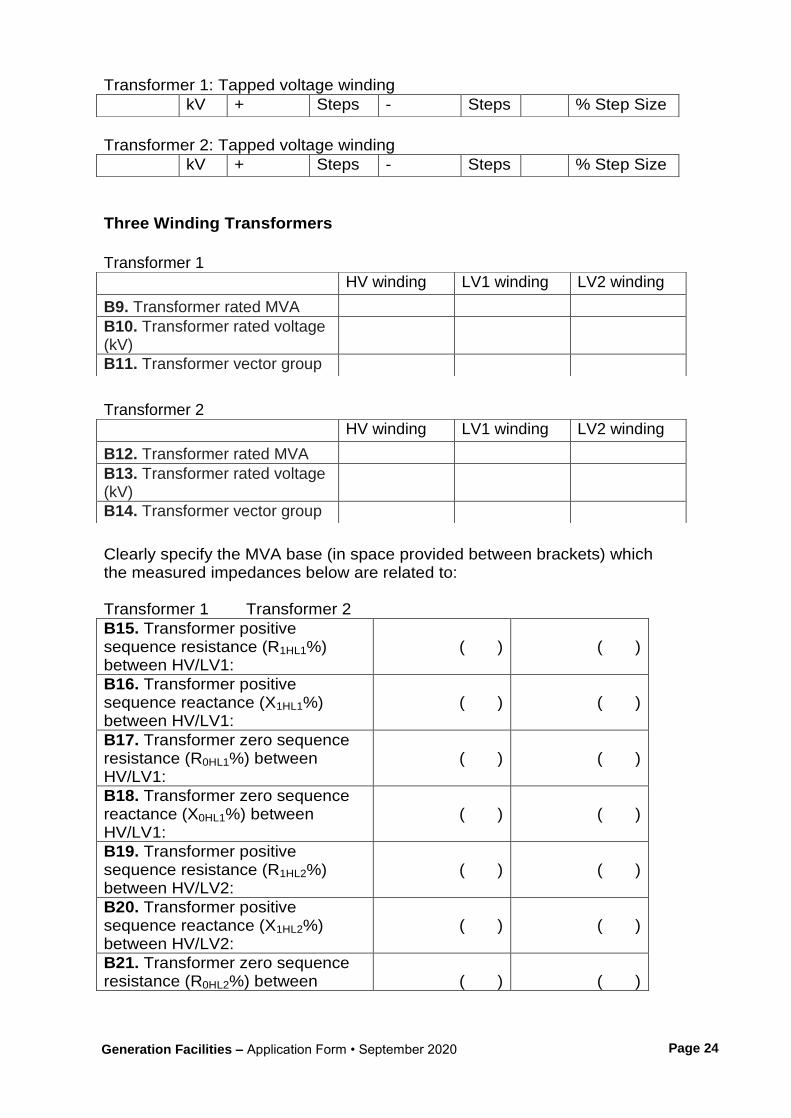
Transformer 1: Tapped voltage winding
Transformer 2: Tapped voltage winding
Three Winding Transformers
Transformer 1
Transformer 2
Clearly specify the MVA base (in space provided between brackets) which the measured impedances below are related to: Transformer 1 Transformer 2
kV + Steps - Steps % Step Size
kV + Steps - Steps % Step Size
HV winding LV1 winding LV2 winding
B9. Transformer rated MVA
B10. Transformer rated voltage (kV)
B11. Transformer vector group
HV winding LV1 winding LV2 winding
B12. Transformer rated MVA
B13. Transformer rated voltage (kV)
B14. Transformer vector group
B15. Transformer positive sequence resistance (R1HL1%) between HV/LV1:
( )
( )
B16. Transformer positive sequence reactance (X1HL1%) between HV/LV1:
( )
( )
B17. Transformer zero sequence resistance (R0HL1%) between HV/LV1:
( )
( )
B18. Transformer zero sequence reactance (X0HL1%) between HV/LV1:
( )
( )
B19. Transformer positive sequence resistance (R1HL2%) between HV/LV2:
( )
( )
B20. Transformer positive sequence reactance (X1HL2%) between HV/LV2:
( )
( )
B21. Transformer zero sequence resistance (R0HL2%) between
( )
( )

Generation Facilities – Application Form • September 2020
Page 25
B31. Please provide details of tap changer. Nature of tap changer (off load/on load/off circuit): Transformer 1 : Tapped voltage winding
Transformer 2 : Tapped voltage winding
HV/LV2:
B22. Transformer zero sequence reactance (X0HL2%) between HV/LV2:
( )
( )
B23. Transformer positive sequence resistance (R1L1L2%) between LV1/LV2:
( )
( )
B24. Transformer positive sequence reactance (X1L1L2%) between LV1/LV2:
( )
( )
B25. Transformer zero sequence resistance (R0L1L2%) between LV1/LV2:
( )
( )
B26. Transformer zero sequence reactance (X0L1L2%) between LV1/LV2:
( )
( )
B27. Transformer positive sequence resistance (R1HL1L2%) between HV/(LV1+LV2):
( )
( )
B28. Transformer positive sequence reactance (X1HL1L2%) between HV/(LV1+LV2):
( )
( )
B29. Transformer zero sequence resistance (R0HL1L2%) between HV/(LV1+LV2):
( )
( )
B30. Transformer zero sequence reactance (X0HL1L2%) between HV/(LV1+LV2):
( )
( )
kV + Steps - Steps % Step Size
kV + Steps - Steps % Step Size

Generation Facilities – Application Form • September 2020
Page 26
Appendix C Conventional Generation Units Generator Data
Unit 1 Unit 2 Unit 3
C1.Xd – Generator Direct Axis Positive Phase Sequence Synchronous Reactance: (pu machine MVA base)
C2.Xq – Generator Quadrature Axis Positive Phase Sequence Synchronous Reactance: (pu machine MVA base)
C3.Xq’ – Generator Quadrature Axis Transient Reactance (unsaturated): (pu machine MVA base) (Note: Not applicable to induction generators).
C4.Xl – Armature Leakage Reactance: (pu machine MVA base)
C5.Tdo‘ – Generator Direct Axis Transient Open Circuit Time Constant: (Sec)
C6.Tdo’’ – Generator Direct Axis Subtransient Open
C7.Tqo’ – Generator Quadrature Axis Transient Open Circuit Time Constant: (Sec)
C8.Tqo’’ – Generator Quadrature Axis Subtransient Open Circuit Time Constant: (Sec)
C9.H – Inertia of complete turbogenerator including primemover gearbox if fitted (MWs/MVA)

Generation Facilities – Application Form • September 2020
Page 27
Appendix D Conventional Generation Units Magnetisation Saturation Curves D1. Please submit the open-circuit generator magnetic saturation curve. If this data is not available at this stage EirGrid will assume the magnetic saturation characteristics for the generator to be in accordance with figure below. Complete tick the appropriate boxes for the following section: Please assume generator magnetic saturation curve as per Figure 1. OR Please assume other generator magnetic saturation curve. Name of attachment specifying curve:
p.u. Saturation Function S(x) S(1.0)=0.10 S(1.2)=0.33 The saturation function is defined in terms of the open terminal voltage versus field current characteristics shown below in Figure 1. From this figure we define: S(1.2)=(A1.2-B1.2)/B1.2
S(1.0)=(A1.0-B1.0)/B1.0
Figure 1: Magnetisaton Saturation Curve

Generation Facilities – Application Form • September 2020
Page 28
Appendix E Conventional Generation Units Excitation System E1. Please submit a Laplace-domain control block diagram that represents the generator excitation system in accordance with IEEE standard excitation models or as otherwise agreed with EirGrid. This control block diagram should specify all time constants and gains to fully explain the transfer function from the compensator or generator terminal voltage and field current to generator field voltage. A list of acceptable IEEE standard excitation models available within the PSS/E simulation package used by EirGrid is shown below. Excitation System Models Below is a list of the standard excitation system models contained in the PSS/E dynamics model library. ESAC1A 1992 IEEE type AC1A excitation system model ESAC2A 1992 IEEE type AC2A excitation system model ESAC3A 1992 IEEE type AC3A excitation system model ESAC4A 1992 IEEE type AC4A excitation system model ESAC5A 1992 IEEE type AC5A excitation system model ESAC6A 1992 IEEE type AC6A excitation system model ESAC6A 1992 IEEE type AC6A excitation system model ESAC8B Basler DECS model ESDC1A 1992 IEEE type DC1A excitation system model ESDC2A 1992 IEEE type DC2A excitation system model ESST1A 1992 IEEE type ST1A excitation system model ESST2A 1992 IEEE type ST2A excitation system model ESST3A 1992 IEEE type ST3A excitation system model ESST4B IEEE type ST4B potential or compounded source-controlled rectifier exciter EX2000 EX2000 Excitation system EXAC1 1981 IEEE type AC1 excitation system model EXAC1A Modified type AC1 excitation system model EXAC2 1981 IEEE type AC2 excitation system model EXAC3 1981 IEEE type AC3 excitation system model EXAC4 1981 IEEE type AC4 excitation system model EXBAS Basler static voltage regulator feeding dc or ac rotating exciter model EXDC2 1981 IEEE type DC2 excitation system model EXELI Static PI transformer fed excitation system model EXPIC1 Proportional/integral excitation system model EXST1 1981 IEEE type ST1 excitation system model EXST2 1981 IEEE type ST2 excitation system model EXST2A Modified 1981 IEEE type ST2 excitation system model EXST3 1981 IEEE type ST3 excitation system model IEEET1 1968 IEEE type 1 excitation system model IEEET2 1968 IEEE type 2 excitation system model IEEET3 1968 IEEE type 3 excitation system model

Generation Facilities – Application Form • September 2020
Page 29
IEEET4 1968 IEEE type 4 excitation system model IEEET5 Modified 1968 IEEE type 4 excitation system model IEEEX1 1979 IEEE type 1 excitation system model and 1981 IEEE type DC1 model IEEEX2 1979 IEEE type 2 excitation system model IEEEX3 1979 IEEE type 3 excitation system model IEEEX4 1979 IEEE type 4 excitation system,1981 IEEE type DC3 and 1992 IEEE type DC3A models IEET1A Modified 1968 IEEE type 1 excitation system model IEET1B Modified 1968 IEEE type 1 excitation system model IEET5A Modified 1968 IEEE type 4 excitation system model IEEX2A 1979 IEEE type 2A excitation system model SCRX Bus or solid fed SCR bridge excitation system model SEXS Simplified excitation system model URST5B IEEE proposed type ST5B excitation system (obsolete) URST5T IEEE proposed type ST5B excitation system Shunted Fed Excitation Model with Typical Parameters Figure 2 represents the excitation model assumed. Parameters are set so to bypass the negative current logic. SCRX
Figure 2: Shunted Fed Excitation Model with Typical Parameters
Value Description
0.1 TA/TB
10 TB (seconds)
200 K
0.05 TE (seconds)
0 EMIN
4 EMAX
0 CSWITCH

Generation Facilities – Application Form • September 2020
Page 30
Appendix F Conventional Generation Units Power System Stabiliser (PSS) F1. Please provide the details of the proposed Power system stabiliser (PSS) to be installed. Noted Name of attachment:
Appendix G Conventional Generation Units Turbine – Governor System Models
G1. Please submit a Laplace-domain control block diagram that represents the generator’s turbine-governor system in accordance with IEEE standard turbine-governor models or as otherwise agreed with EirGrid. This control block diagram should specify all time constants and gains to fully explain the transfer function from the compensator or generator terminal voltage and field current to generator field voltage. A list of acceptable IEEE standard turbine-governor models available within the PSS/E simulation package used by EirGrid is shown below. Complete the following section as appropriate: A. Please assume model from list below. Name of attachment detailing the data parameters for the specified turbine-governor model:
OR B. Please assume other model: Name of attachment specifying model and all necessary data parameters: OR C. If turbine-governor system data is not available at this stage EirGrid will assume a standard model with corresponding parameters for the turbine-governor system. The assumed turbine-governor model for dynamic simulation is detailed in Figure 3 below.

Generation Facilities – Application Form • September 2020
Page 31
Please assume the model detailed in Figure 3 as our turbine-governor system. Below is a list of the standard turbine-governor system models contained in the PSS/E dynamics model library. CRCMGV Cross compound turbine-governor model DEGOV Woodward diesel governor model DEGOV1 Woodward diesel governor model GAST Gas turbine-governor model GAST2A Gas turbine-governor model GASTWD Gas turbine-governor model HYGOV Hydro turbine-governor model IEEEG1 1981 IEEE type 1 turbine-governor model IEEEG2 1981 IEEE type 2 turbine-governor model IEEEG3 1981 IEEE type 3 turbine-governor model IEESGO 1973 IEEE standard turbine-governor model PIDGOV Hydro turbine and governor model TGOV1 Steam turbine-governor model TGOV2 Steam turbine-governor model with fast valving TGOV3 Modified IEEE type 1 turbine-governor model with fast valving TGOV5 Modified IEEE type 1 turbine-governor model with boiler controls WEHGOV Woodward electronic hydro governor model WESGOV Westinghouse digital governor for gas turbine WPIDHY Woodward P.I.D. hydro governor model
Governor System Model Typical Parameters
Figure 3: Turbine – Governor System Model
Value Description
0.04 R
0.5 T1(>0) seconds
0.85 Vmax
0.2 Vmin
2 T1(>0) seconds
7 T1(>0) seconds
0 Dt

Generation Facilities – Application Form • September 2020
Page 32
Appendix H
Application form completed in full,
Application fee,
Two signed copies of confidentiality agreement (if applicable),
OS map,
Single line diagram (SLD), soft copy,
Site plan including site boundary (soft copy),
Power curve –soft copy,
Power quality test report (if applicable),
Reactive power capability curve,
Fault ride through capability test results (if applicable),
Internal network structure details (if applicable),
Station data (if applicable),
Short circuit decrement curve (if applicable),
Suitable dynamics model and
Functional block diagram of plant (if applicable).